ote technical note technical atlantic city international
TRANSCRIPT

System Integration Study of Voice over Internet Protocol for National Airspace System Ground-to-Ground Communications Phase II Final Report Eduardo Colón-Madera, AJP-7A3 Radamé Martínez, AJP-7A3 Alok Gulati, AJP-7A3 Jose A. Lugo, AJP-7A3 Carol Pisano, AJP-7A3 Michael Press, AJP-7A3 Tuan A. Tran, AJP-7A3 Eva Balassa, STG Technologies September 2009 DOT/FAA/TC-TN10/1 This document is on file at the FAA William J. Hughes Technical Center Reference and Research Library, Atlantic City International Airport, New Jersey 08405, at Internet address http://actlibrary.tc.faa.gov.
U.S. Department of Transportation Federal Aviation Administration William J. Hughes Technical Center Atlantic City International Airport, NJ 08405
ote
tech
nica
l not
e te
chni
cal

ii
NOTICE
This document is disseminated under the sponsorship of the U.S. Department of Transportation in the interest of information exchange. The United States Government assumes no liability for the contents or use thereof. The United States Government does not endorse products or manufacturers. Trade or manufacturers’ names appear herein solely because they are considered essential to the objective of this report. This document does not constitute Federal Aviation Administration (FAA) certification policy. Consult your local FAA aircraft certification office as to its use. This report is available at the FAA William J. Hughes Technical Center’s full-text Technical Reports Web site: http://actlibrary.tc.faa.gov in Adobe® Acrobat® portable document format (PDF).

iii
Abstract DOT F1700.7
, I I ~ ! I , I I i
Goo" Goo"
, .

iv
(This page is intentionally blank.)

v
Table of Contents
Abstract DOT F1700.7..................................................................................................................... iii List of Figures .................................................................................................................................. vi List of Tables ................................................................................................................................... vi Summary ........................................................................................................................................... 1
1 Introduction................................................................................................................................. 3 1.1 Purpose of Report ................................................................................................................. 3 1.2 Scope of Report..................................................................................................................... 3
2 System Description...................................................................................................................... 3 2.1 Mission Review .................................................................................................................... 3 2.2 System Configuration ........................................................................................................... 3
3 Study Description........................................................................................................................ 8 3.1 Objectives and Criteria ......................................................................................................... 8 3.2 Study Descriptions, Schedules, Locations, and Participants ................................................ 8
3.2.1 Test Bed Performance................................................................................................... 8 3.2.1.1 Throughput................................................................................................................ 8 3.2.1.2 Latency...................................................................................................................... 9 3.2.1.3 Latency Distribution ................................................................................................. 9
3.2.2 Unit Test........................................................................................................................ 9 3.2.2.1 Delay ....................................................................................................................... 10 3.2.2.2 Jitter......................................................................................................................... 10 3.2.2.3 Injected Packet Loss ............................................................................................... 10
3.2.3 Integrated System........................................................................................................ 11 3.3 Data Collection and Analysis Method ................................................................................ 11 3.4 Results and Discussion ....................................................................................................... 14
3.4.1 Test Bed Performance................................................................................................. 15 3.4.1.1 Throughput.............................................................................................................. 15 3.4.1.2 Latency.................................................................................................................... 16 3.4.1.3 Latency Distribution ............................................................................................... 18
3.4.2 Unit Test...................................................................................................................... 18 3.4.2.1 Delay ....................................................................................................................... 19 3.4.2.2 Jitter......................................................................................................................... 20 3.4.2.3 Injected Packet Loss ............................................................................................... 22
3.4.3 Integrated System........................................................................................................ 22 4 Conclusions................................................................................................................................ 26
4.1 Throughput.......................................................................................................................... 27 4.2 Delay ................................................................................................................................... 27 4.3 Latency................................................................................................................................ 27 4.4 Latency Distribution ........................................................................................................... 27 4.5 Jitter..................................................................................................................................... 27 4.6 Injected Packet Loss ........................................................................................................... 27
5 Recommendations ..................................................................................................................... 28 Bibliography ................................................................................................................................... 29 Abbreviations and Acronyms ......................................................................................................... 31

vi
List of Figures
Figure 1 Architecture Used for the VoIP SIS.................................................................................. 7 Figure 2 IP-to-IP Communications Diagram ................................................................................ 13 Figure 3 IPv4 and IPv6 Comparison of Average One-Way Delay with Injected Jitter ................ 21 Figure 4 Comparison of IPv4 and IPv6 Maximum RTP Jitter with Injected Jitter....................... 21 Figure 5 NAS Switches and VoIP Network.................................................................................. 26
List of Tables
Table 1 Trunk Types Evaluated ..................................................................................................... 5 Table 2 SmartBits 6000B Throughput Measurements (Port rate 100 Mb/s Full Duplex)............. 9 Table 3 Rates of Packet Loss Injected by ConNIE...................................................................... 11 Table 4 Test Equipment with Configured Features ..................................................................... 14 Table 5 Test Equipment with Parameters Measured ................................................................... 14 Table 6 Understanding SmartBits 6000B Load Parameters ........................................................ 15 Table 7 IPv4 Results of Loading Scenario for Full T1 CIR ........................................................ 16 Table 8 IPv6 Results of Loading Scenario for Full T1 CIR ........................................................ 16 Table 9 IPv4 Total Round-Trip Latency Baseline at 0.772% of Full T1 CIR............................. 17 Table 10 IPv6 Total Round-Trip Latency Baseline at 0.772% of Full T1 CIR............................. 17 Table 11 IPv4 One-Way Data Flow Latency at 0.772% of Full T1 CIR....................................... 17 Table 12 IPv6 One-Way Data Flow Latency at 0.772% of Full T1 CIR....................................... 18 Table 13 Average values for G.729AB Codec, SIP Protocol, and Full T1 CIR (IPv4)................. 19 Table 14 Average values for G.729AB Codec, SIP Protocol, and Full T1 CIR (IPv6)................. 19 Table 15 Injected Jitter IPv4 at Full T1 CIR.................................................................................. 20 Table 16 Injected Jitter IPv6 at Full T1 CIR.................................................................................. 20 Table 17 Effect of Injected Packet Loss on R-factor* ................................................................... 22 Table 18 Subjective Assessment Rating ........................................................................................ 23 Table 19 Trunk Types Signaling Methods..................................................................................... 23

1
Summary
Under the sponsorship of the Air Traffic Organization (ATO) – NextGen and Operations Planning (AJP) Systems Engineering and Safety Office, National Airspace System (NAS) Enterprise Architecture Group, the William J. Hughes Technical Center (hereinafter, “Technical Center”) Test and Evaluation Services Group Communications Team (AJP-7A3) was tasked to design and configure a Voice over Internet Protocol (VoIP) test bed to evaluate the feasibility of VoIP technologies in the NAS environment. This System Integration Study (SIS) documents Phase II of the study conducted from May 2008 to May 2009.
The Communications Team evaluated Internet Protocol (IP) versions 4 and 6. IPv4 is the IP version currently fielded under the FAA Telecommunications Infrastructure (FTI) contract. IPv6 is the future version to be implemented per FAA guidance memorandum dated June 14, 2006. Phase I of the System Integration Study (SIS) focused on VoIPv4 and evaluation of performance and voice quality in the presence of delay and injected errors. The Phase I final report was issued in August 2008. Phase II SIS impairments included jitter, packet drop, and delay for VoIPv4 and v6. VoIP was implemented with Session Initiation Protocol (SIP) and G.729AB codec. Implementation of VoIPv6 in the test bed was limited since the technology supporting VoIPv6 is currently evolving.
The SIS was designed to investigate and thereby mitigate potential risks related to transitioning the ground-to-ground (G-G) telecommunications infrastructure from a combination of analog and digital to an all-digital technology. The study investigated the feasibility and reliability of transporting G-G communications over a VoIP network without degrading voice quality. Although the study followed Acquisition Management System (AMS) testing guidelines (tailored), it should not be considered a formal test effort. The study, conducted in a laboratory environment, provides a solid foundation for any future formal test effort.
The VoIP test bed is made up of commercial off-the-shelf (COTS) products that comply with accepted industry standards. The VoIP test bed topology consists of two nodes, with each node consisting of dedicated equipment and addressing schemes, and configured in a dual-stack (i.e., either IPv4 or IPv6 capable) mode able to interface with NAS voice switch systems.
A preliminary statement of work (SOW), dated July 2006, outlined several areas for analysis. The SOW was generated by the Operations Planning Systems Engineering Directorate, now known as the ATO – NextGen and Operations Planning (AJP) Systems Engineering and Safety Office. Within the constraints imposed by the limited resources allocated, the SIS facilitates the evaluation of several of those SOW areas as they relate to the NAS. The VoIP test bed design was implemented considering the assumptions stated in Section 3.1 of the Implementation of Voice over Internet Protocol (VoIP) For NAS Interfacility Communications: Reference Guide Version 1.1 prepared by the Systems Engineering and Safety Office.
The Communications Team concluded the following:
The VoIP test bed supports VoIPv4 and VoIPv6 G-G communications with current NAS voice systems.
VoIP COTS products are not completely ready to support IPv6. Industry is working on infrastructure and code to support VoIPv6 applications (e.g., VoIPv6 dial peer configurations were not available from Cisco prior to October 2008).
The G.729AB codec showed good performance in terms of bandwidth consumption and voice quality. It performed satisfactorily in presence of injected impairments. However,

2
G.729AB would be best suited for a voice-only network. This codec is vulnerable to impairments such as packet loss and jitter.
The analog to IP conversion required when interfacing the legacy system with VoIP will produce an inherent delay.
Voice calls show good voice quality results (e.g., R-factor) in presence of injected jitter up to a maximum of 30 ms per packet.
Packet loss should be less than one packet per 400 to avoid adverse effect on voice quality. Any greater rate of packet loss should be considered unacceptable.
The Communications Team recommends continued evaluation of VoIP integration into NAS voice communication systems. And, if VoIP is implemented in the NAS, the selected protocol should be IPv6. NAS VoIP traffic should travel on a separate secure network backbone. However, if a converged (voice and data) approach is selected, quality of service (QoS) and security policies must be implemented. Follow on evaluations should demonstrate (a) additional sector communications (e.g., a third node to simulate a third site; third NAS switch), (b) communication with two other locations simultaneously, and (c) failover scenarios.
Additional recommendations are as follows:
A thorough investigation of operational call volume and bandwidth used for voice in the current FAA NAS environment should be conducted to properly design the backbone and create a baseline for VoIP QoS.
Create network requirements that include IP addressing structures and security standards to provide high levels of availability, integrity, performance, and QoS for VoIP in NAS applications.
An evaluation of the effect of security features on latency and voice quality should be conducted (e.g., security features such as Internet Protocol Security (IPsec)).
To facilitate the transition of the legacy systems to VoIP, COTS products are needed to (a) convert voice switch trunk signaling to T1, and (b) improve dial plans and call routing.
Evaluation of future NAS voice switches or VoIP services should include packet loss and jitter in test scenarios, since these are conditions inherent in a real-world environment.
A true Mean Opinion Score (MOS) evaluation with Air Traffic Control (ATC) involvement should be conducted for VoIP services and codecs (e.g., G.711u-law, G726, and G.729AB).
All evaluations should follow guidelines detailed in the Test and Evaluation Handbook.

3
1 Introduction
1.1 Purpose of Report
The Federal Aviation Administration (FAA) is undertaking a modernization of the voice infrastructure by planning and implementing mature, scalable, and cost effective Transmission Control Protocol/Internet Protocol (TCP/IP) technology.
Current FAA Air Traffic Management (ATM) voice switching systems provide air traffic controllers with the capability to establish air-ground (A-G) and ground-ground (G-G) voice communications. These systems need a reliable network to connect different elements of the NAS to provide voice, data, and video communications services.
Under the sponsorship of the Air Traffic Organization (ATO) – NextGen and Operations Planning (AJP) Systems Engineering and Safety Office, NAS Enterprise Architecture Group, the William J. Hughes Technical Center (hereinafter, “Technical Center”) Test and Evaluation Services Group Communications Team (AJP-7A3) was tasked to design and configure a Voice over Internet Protocol (VoIP) test bed to evaluate the feasibility of VoIP technologies in the NAS environment.
1.2 Scope of Report
This report contains results of a system integration study (SIS) utilizing Voice over Internet Protocol (IP) version 6 (VoIPv6) with comparisons to VoIPv4 results. The VoIPv6 performance and voice quality evaluations are based on those defined in the Plan for the System Integration Study (SIS) of Voice over Internet Protocol (IP) version 4 (VoIPv4) for NAS G-G Communication Systems (the Test Plan) dated March 30, 2007. That is, the evaluations for performance and voice quality in the Test Plan were modified to use VoIPv6 in place of VoIPv4.
A brief outline of the contents and arrangement of this report is shown below.
Section 1 Describes the purpose and a brief overview of this report.
Section 2 Contains an overview of the VoIP test bed and its interfaces.
Section 3 Details study description and results.
Section 4 Contains study conclusions.
Section 5 Lists study recommendations.
2 System Description
2.1 Mission Review
The VoIP test bed is a converged network (i.e., voice and data) that is capable of providing IP ground-to-ground communications between existing NAS Air Traffic Control (ATC) switches. The test bed is located in the Communications Team laboratory at the Technical Center.
2.2 System Configuration
The VoIP test bed design is a two-node topology implemented with internet protocol version four and six (IPv4 and IPv6). Each node has a dedicated set of equipment and addressing scheme. The two nodes are referred to as the Technical Center Site (TCS) and the Miami Center (ZMA). A preliminary Statement of Work (SOW), dated July 2006, outlined several areas for analysis. The

4
preliminary SOW was generated by the Operations Planning Systems Engineering Directorate (now known as the ATO NextGen and Operations Planning Systems Engineering and Safety Office). Within the constraints imposed by the limited resources allocated, this study evaluates several areas as they relate to the NAS. The VoIP test bed is a converged IP network that interfaces with the following NAS ATC switches:
Voice Switching and Control System (VSCS)
VSCS Training and Backup System (VTABS)
Enhanced Terminal Voice Switch (ETVS)
Interim Voice Switch Replacement (IVSR)
Definition of the voice switching infrastructure used in this study is based on the following assumptions that reflect concepts described in Section 3.1 of the Implementation of Voice over Internet Protocol (VoIP) For NAS Interfacility Communications: Reference Guide prepared by the Operations Planning Systems Engineering Directorate (now known as the ATO NextGen and Operations Planning Systems Engineering and Safety Office).
1 A robust IP infrastructure exists that supports Air Traffic Management (ATM) requirements (e.g. availability, performance, Quality of Services (QoS), security) at ATM facilities.
The VoIP test bed satisfies this assumption. The infrastructure was designed to support IPv4 and IPv6, VoIPv4 and VoIPv6, and implemented mechanisms to support quality of service (QoS). A basic security mechanism was implemented with access control lists (ACLs) and virtual local area network (VLAN).
2 Interfaces are available to the [FAA] private switched telephone network for backup and load sharing.
3 The IP infrastructure is compatible with the legacy end systems (e.g., voice switches, circuits), and signaling protocols.
Interfaces used satisfy assumptions 2 and 3; they are as follows:
E&M (commonly known as “ear & mouth”) interfaces in two- or four-wire configurations
T1 interfaces
Foreign exchange office (FXO) interfaces
Foreign exchange station (FXS) interfaces
Interfaces in four-wire configurations for single-frequency (SF) signaling, selective signaling (SS-1), and VOX signaling
Ethernet interfaces (10 Mb/s, full and half duplex; 100 Mb/s, full and half duplex; 1 Gb/s, full duplex)
4 Member states manage the portions of the network within their respective domains.
5 Provisions are available for fixed wireless links (e.g., satellite).
The two-node approach satisfied assumption number 4, above. Each node has its own network addressing scheme and segments. This approach could also satisfy the routing of calls within or outside an FAA sector or network domain. The VoIP test bed uses the Bandwidth Manager/FAA IP-Routed Multi-user Network (BWM/FIRMNet) backbone test node as an internet service provider

5
(ISP) transport cloud. This backbone has the capability to provide links as stated in assumption number 5, but this was outside the current scope of this report.
6 ATM-QSIG [Q Signaling protocol] signaling is integrated within the voice communications network for international interfaces.
7 Sufficient implementation of redundancy.
Assumptions 6 and 7 were not addressed due to limited resources.
The BWM customer premises equipment (CPE) was configured to interface with ATC voice switches. Equipment was dedicated to the implementation and evaluation of VoIP communication. COTS hardware and software tools used in the test bed design are listed below.
Windows® 2003 Domain Name System/Dynamic Host Configuration Protocol (DNS/DHCP) server
- Used to register and update the pointer and host resource records on behalf of its DHCP-enabled clients on IPv4 and IPv6
Asterisk® Session Initiation Protocol (SIP)-based IP server-client
- Used to assure the correct registration of the SIP VoIP calls between destinations on IPv4 and v6
To accommodate multiple signaling arrangements from the voice switches, the following components were included in the test bed.
Channel Banks. These are used to group the Type 3, Type 5, Type 7, and Type 9 interfaces from the voice switches and translate them to a T1 interface. These devices were configured as transmit only, 2600 Hz detect, and E&M Type I and II. As shown in Table 1, most of the integrations were achieved using an E&M Type I interface. Most of the fielded VSCS G-G switch interfaces are 4-wire E&M Type I connected at the switch back pane. This was tested and verified in an effort to consider the elimination of the Tellabs® E&M-to-E&M converter cards.
Cisco® voice-enabled gateway (Cisco 2821) and Gatekeeper (Cisco 7206) routers. Voice configurations were implemented in these devices to verify the signaling provided by the voice gateways for IP and non-IP users. Types of calls handled by the gateways were as follows:
- Analog to IP
- IP to Analog
- Analog to Analog, from Voice switch positions
- IP to IP
Table 1 Trunk Types Evaluated
Users Interface Implementation on Channel
Bank #1 Implementation on Channel
Bank #2 VTABS Type 7 2600 Hz Detect 2600 Hz Detect
Users Interface Implementation on Channel
Bank #4 Implementation on Channel
Bank #5 ETVS Type 3 E&M Type I E&M Type I VSCS Type 3 E&M Type I E&M Type I IVSR Type 3 E&M Type I and II E&M Type I and II VTABS Type 5 Transmit only Transmit only VTABS Type 9 Transmit only Transmit only

6
A basic QoS mechanism was implemented using policies, prioritization, and bandwidth allocations for the local area network (LAN) and wide area network (WAN). The LAN consisted of Cisco 2821 Integrated Services Routers, Cisco Catalyst® 3560 Series Layer 3 switches, and channel banks. The Cisco Layer 3 switches are the demarcation points on the LAN interfaces for the IP users, the channel banks are the demarcation point for the analog users.
The WAN consisted of the Spirent® SX/13 Data Link Simulator, Cisco 7513 and 7206 Routers, and the Cisco Layer 2 Catalyst 2950 Series Switches.
Equipment used during the study is listed below.
IP and analog phones
- Clipcomm IP telephones
- Northern Telecom analog telephones
- Twinkle SIP-based softphone
- Voice Switch positions (analog)
Test equipment used to measure the performance of VoIP communications
- Spirent SX/13 Data Link Simulator — used to simulate a WAN and to inject network impairments
- NetworkFX® Converged Network Impairment Emulator (ConNIE®)
- Spirent Abacus 5000 (VoIP quality test equipment and VoIP call generator)
- Spirent SmartBits® 6000B (IPv4 and v6 data generator and network performance test equipment with SmartFlow™ software)
- Sage Model 930A Communications Test Set (a voice frequency measurement tool)
- Wireshark® Network Protocol Analyzer
Communications between voice switch users was point-to-cloud across a simulated WAN link and the VoIP test bed ISP. The system architecture for the VoIP SIS is shown in Figure 1.

7
Figure 1 Architecture Used for the VoIP SIS
dns.faa.goY DNS/DHCP
7227
7336
FOl24 .69 tcs.faa.goY
TCS
FO/3 .05
.43
FO/2
.42
S2/0/2
FOIOIO .02
VolP Test Bed
WAN Emulator Spirent SX13A
ZMA
ConNIE
Voice Gateway Voice Gateway
FO/1 .09
Vo ice .65 Data
.1 T1
NAS Voice Switches =J.,,~ ETVS, VSCS, IVSR
VolP Call
CBS CB4
SmartBits 6000B Data Generation Source
T1
Voice .65
Data .1
NAS Voice Switches ETVS, VSCS, IVSR
Management Connection
Card LAN 30018
E&M trunks
Management Connection
ABACUS 5000 Voice Traffic Generator
Port 0
VolPCali
Asterisk V6
Generated Data
Voice
Networll Traffic
Chanel Bank '" CB

8
3 Study Description
3.1 Objectives and Criteria
The preliminary evaluation strategies for the study are documented in the Test Plan. This report documents the design, construction, and configuration of the VoIP test bed used to evaluate VoIP technologies in the NAS environment. The initiative was developed to support the modernization of FAA ATM G-G voice applications. The main objective was to obtain the test bed performance baseline and voice quality performance measurements with and without network impairments. Scenarios were developed to measure network performance in terms of throughput, latency, and latency distribution. In addition, scenarios were created to evaluate voice quality in the presence of injected impairments such as delay, jitter, and packet loss.
This second phase of study focused on Session Initiation Protocol (SIP) and G.729AB voice calls with impairments in IPv4 and IPv6. Unit tests (UTs) were completed to provide objective evaluations and subjective demonstrations of QoS and voice quality, respectively. Objective evaluation of wave audio file transmissions was performed by the Abacus 5000 test tool from the IP interfaces. Analog interfaces were not completely verified in IPv6 due to technical limitations (the Agilent Advisor VQT test tool was not available and interfaces were not available or not yet developed).
An ad hoc demonstration was conducted and subjective assessments were collected of participants’ perception of the audio quality of spoken test counts in comparison with the measured results provided by the objective tests.
3.2 Study Descriptions, Schedules, Locations, and Participants
The study was conducted using the BWM/FIRMNet test bed and NAS G-G voice switches at the Technical Center. Communications Team (AJP-7A3) personnel coordinated the activities and collected the data. Laboratory Engineering Team (AJP-782) personnel completed baseline verification of the voice switches and provided support during the integration evaluation and during engineering discussions.
The Communications Team developed the VoIP SIS based on a top-down approach that includes segmented evaluations, unit tests (UTs), system integration, and integration evaluations. This approach can be used in future implementations of VoIP in the NAS infrastructure.
All verification activities were conducted in the Communications Team laboratory between May 2008 and May 2009.
3.2.1 Test Bed Performance
Test bed performance measurements established a baseline for network performance. Spirent SmartFlow software was used to obtain baseline measurements. SmartFlow calculated the throughput, latency, and latency distribution of the VoIP test bed.
3.2.1.1 Throughput
This evaluation determined the fastest rate at which the VoIP test bed could forward packets, in IPv6 format, without frame loss. SmartBits 6000B was used to introduce a User Datagram Protocol (UDP) data stream of various frame sizes into the VoIP test bed (the system under test; SUT). Throughput measurements were obtained for the following three bandwidths: 512 kb/s, 768 kb/s,

9
and 1.544 Mb/s. Load values were expressed as a percentage of the port interface rate of 100 Mb/s (200 Mb/s total for transmit and receive). The committed interface rate (CIR) is the rate at which the users connect to the WAN interfaces.
The results presented in Section 3.4.1.1 represent a sample of values for maximum throughput scenarios with zero frame loss. CIR was simulated by the Spirent SX/13 Data Link Simulator (WAN emulator). Table 2 lists the test parameters.
Table 2 SmartBits 6000B Throughput Measurements (Port rate 100 Mb/s Full Duplex)
Committed Interface Rate (CIR) SmartBits 6000B
CIR Percent of CIR Measured Frame Sizes Verified (bytes)
512 kb/s 25 through 100 84, 128, 256, 512, 1024, 1280, 1518
768 kb/s 25 through 100 84, 128, 256, 512, 1024, 1280, 1518
1.544 Mb/s 25 through 100 84, 128, 256, 512, 1024, 1280, 1518
3.2.1.2 Latency
Latency is the total time required for queuing, servicing, and propagation of a packet. Latency in a packet-switched network is measured either one way (the time from the source sending a packet to the destination receiving it), or round trip (the one-way latency from source to destination plus the one-way latency from the destination back to the source).
Latency measurements for the SUT were recorded for IPv4 and IPv6. This evaluation was completed once the load tolerance limits were determined by the throughput and frame loss evaluations. The latency test measured (a) latency variation for each load trial, (b) frame length per port, and (c) the minimum, maximum, and average latency per port.
3.2.1.3 Latency Distribution
Latency distribution expresses the latency characteristics of the SUT. IPv6 latency distribution results were tabulated for eight user-defined latency time parameters (a subset of those results will be presented in Section 3.4.1.3). For each latency range, the number of packets received was recorded. The defined ranges were distributed between 25 ms and 300 ms. This is the same approach used for IPv4 data during Phase I of this study.
International Telecommunications Union - Telecommunication Standardization Sector (ITU-T) Recommendation G.114 notes that if delay is less than 150 ms, then most applications “would not be significantly affected.” Within this limit, users should be satisfied with voice call quality.
This test was run at CIR rates of 512 kb/s, 768 kb/s, and 1.544 Mb/s. Results provided a detailed view of latency behavior at the load tolerance limits of the SUT for UDP traffic. The test tracked latency on a frame-by-frame basis and sorted latency results into eight latency ranges. Latency was calculated by comparing frame transmit and receive timestamps.
3.2.2 Unit Test
Phase II of this study focused on SIP signaling protocol and G.729AB codec. This signaling protocol and codec combination was implemented over IPv6. After the baseline data were collected,

10
impairments were injected to the SUT and the effects of those impairments were measured to evaluate the codec and the signaling protocol performance.
3.2.2.1 Delay
The specific type of delay evaluated for the SUT was propagation delay. Propagation delay is the time it takes for a packet to traverse the medium through which it is being transmitted. Point-to-Point Protocol (PPP) over a serial connection was used for the WAN and Fast Ethernet (IEEE 802.3u standard) was used for the LAN.
Baseline delay measurements were recorded with “send UDP” packets from (a) test nodes and (b) by creating one end-to-end voice call. Each measurement was documented as the baseline system delay. Delays were injected to the SUT by the SX/13 Data Link Simulator. The delay injected into each node ranged from 25 ms to 250 ms in increments of 25 ms. Voice quality evaluations were conducted as stated in Section 3.1 of this document. Abacus 5000 was used to capture objective measurements of (a) Rating factor (R-factor), (b) the perceptual evaluation of speech quality (mean opinion score - listening quality objective) (PESQ(MOS-LQO)), and (c) Real-time Transport Protocol (RTP) jitter while delay was injected. These are three measurements of overall VoIP call quality.
The International Telecommunication Union - Telecommunication Standardization Sector (ITU-T) Recommendation G.107 defines R-factor as a value derived from metrics such as latency, jitter, and packet loss. R-factor provides a quick assessment of the quality-of-experience for VoIP calls. Typical R-factor scores range from 50 (bad) to 90 (excellent). ITU Recommendation G.107 indicates a maximum R-factor of approximately 72 with the G.729AB codec. Baseline R-factor measurements in the VoIP test bed ranged from 72 to 72.2.
3.2.2.2 Jitter
Jitter is the variation in the delay of received packets. RTP jitter is variation in the delay of received RTP (i.e., voice) packets. Abacus 5000 recorded jitter and RTP jitter values. Abacus 5000 reported RTP jitter based on received RTP Control Protocol (RTCP) packets. The Wireshark network protocol analyzer captured RTP jitter. All jitter measurements represented the characteristics of the SUT. Jitter was injected artificially with the ConNIE test tool. The Abacus 5000 provided measurements of network performance in delivery of voice RTP traffic.
3.2.2.3 Injected Packet Loss
Packet loss, also referred to as packet drop, can occur for several reasons including: network congestion, timeouts, route flapping, link disconnects, among other causes. In our environment, packets were dropped intentionality to measure the effect on voice traffic. Packet loss was injected periodically at the rate of 1 per n packets, with n equal to an integer between 1 and 10,000,000. For example, if n = 1,000 then every 1,000th packet will be dropped. The ConNIE test suite injected the impairment and assigned a percentage value to each impairment rate. See Table 3 below.

11
Table 3 Rates of Packet Loss Injected by ConNIE
ConNIE Setting (%) Rate of Packet Loss
0.2000000 Every 500th packet is dropped 0.2222222 Every 450th packet is dropped 0.2500000 Every 400th packet is dropped 0.3000000 Every 334th packet is dropped 0.3333333 Every 300th packet is dropped 0.4000000 Every 250th packet is dropped 0.5000000 Every 200th packet is dropped 0.5555555 Every 180th packet is dropped 0.6024096 Every 166th packet is dropped 0.6578947 Every 152nd packet is dropped 0.7042254 Every 142nd packet is dropped 0.7518797 Every 133rd packet is dropped 0.8000000 Every 125th packet is dropped 0.8547009 Every 117th packet is dropped 0.9009009 Every 111th packet is dropped 1.0000000 Every 100th packet is dropped 2.0000000 Every 50th packet is dropped
An ad hoc demonstration was conducted and subjective assessments were collected of participants’ perception of the audio quality of spoken test phrases (assessment ratings are shown in Table 18). Abacus 5000 was used to report PESQ, R-factor, and channel errors. The effect of injected packet loss was evaluated for VoIPv4 and VoIPv6 calls across the VoIP test bed. Results are shown in Table 17.
3.2.3 Integrated System
The integrated system permitted evaluation of G-G communications (a) between voice switches, and (b) between voice switches and other IP and non-IP devices. End users verified that implementation of VoIP did not adversely affect the performance and operation of the voice switches. Subjective assessments were based on the demonstration participants’ perception of the audio quality of spoken test counts.
3.3 Data Collection and Analysis Method
The VoIP evaluations were conducted in a controlled laboratory environment. Abacus 5000 and SmartBits 6000B generated reports of test results. Report data were summarized in spreadsheets. Results provided a basis to evaluate overall VoIP implementation performance (e.g., quality of service and voice quality). Voice quality was assessed with objective evaluations and subjective demonstrations.
The UT and integrated system evaluation process is outlined below.
1) IP to IP evaluation (see Figure 2)
a) Baseline i) QoS - Objective evaluation using Abacus 5000 ii) Voice quality - Subjective assessment by demonstration participants
b) Delay injected by Spirent SX/13 Data Link Simulator i) QoS - Objective evaluation using Abacus 5000

12
ii) Performance - Objective evaluation using Wireshark iii) Voice quality - Subjective assessment by demonstration participants
c) Jitter and packet loss injected by ConNIE i) QoS - Objective evaluation using Abacus 5000 ii) Performance - Objective evaluation using Wireshark iii) Voice quality - Subjective assessment by demonstration participants
2) Analog to IP evaluation
a) Baseline i) QoS - Objective evaluation using Abacus 5000 (this step verified that the network was
working correctly at the moment) ii) Performance - Objective evaluation using Wireshark iii) Voice quality - Subjective assessment by demonstration participants
b) Delay injected by Spirent SX/13 Data Link Simulator i) QoS - Objective evaluation using Abacus 5000 ii) Performance - Objective evaluation using Wireshark iii) Voice quality - Subjective assessment by demonstration participants
c) Jitter and packet loss injected by ConNIE i) QoS - Objective evaluation using Abacus 5000 ii) Performance - Objective evaluation using Wireshark iii) Voice quality - Subjective assessment by demonstration participant

13
Figure 2 IP-to-IP Communications Diagram
FO/3
.43
dns.faa.gov DNSIDHCP
FO/2
.42
asterisk.faa.gov
7227
7336
FO/24 .69 tcsJaa.gov
IPPBX
VolP Call
FOl1
.09
TCS
Voice .65 Data
.1
.10
VolP Test Bed
FOIOIO .02
Voice Gateway
Man<lgement Connection
(01 , 02, 01) Port 1
I . . ....
WAN Emulator Spirent SX13A
ZMA
ConNIE
Voice Gateway
SmartBits 60008 Data Generation Source
Card LAN 30018
Port 6 (01, 02, 06)
Management Connection
ABACUS 5000 Voice Traffic Generator
Port 0
Voice .65
Data .1
BWMLab - 2003 Server
Asterisk V6
VolP Call
Generated Data
Voice
Network Traffic
Chanel Bank" CS

14
Table 4 is a compilation of test equipment with configured features. Table 5 is a compilation of test equipment and the parameters available for measurement.
Table 4 Test Equipment with Configured Features
Configured Features Abacus 5000 SmartBits 6000B ConNIE Port Rate (Interface) 100 Mb/s 100 Mb/s 100 Mb/s
Network Interface IPv4 and IPv6 IPv4 and IPv6 IPv4 and IPv6 Channel Full Duplex Full Duplex Full Duplex Protocol SIP UDP IPv4 and IPv6 Codec G.729AB N/A N/A
Frame Size N/A 84, 128, 256, 512 1024,
1218, 1518 N/A
Injected Packet loss N/A N/A √ Injected Out of sequence N/A N/A √
Injected Delay (ms) N/A N/A √ Network Analyzer √ √ √
√ – used X – feature not implemented N/A – not available
Table 5 Test Equipment with Parameters Measured
Configured Parameters Abacus 5000 SmartBits 6000B ConNIE Protocol SIP UDP IPv4 and IPv6
Network Interface IPv4 and IPv6 IPv4 and IPv6 IPv4 and IPv6 Quality of Service and
Voice Quality √ N/A N/A
Voice Quality √ N/A N/A Latency X √ N/A
Frame Loss X √ N/A Throughput N/A √ N/A
Packets Transmitted √ √ √ Packets Received √ √ √
One-way Delay (ms) √ √ Real-Time Transport Protocol (RTP) Jitter
√ N/A N/A
Jitter √ N/A √ Call Setup Time (ms) √ N/A N/A
RTP Packet Loss √ X N/A PESQ √ X N/A
Post-Dial Delay (ms) √ X N/A PESQ (MOS-LQO) √ X N/A
Packets Out of Order √ N/A √ Packet Loss N/A √ √
√ – used X – feature not implemented N/A – not available
3.4 Results and Discussion
VoIP implementations were evaluated by (a) performance in the test bed, (b) UTs, and (c) integrated system performance.

15
3.4.1 Test Bed Performance
Prioritized voice traffic over the LAN and WAN was implemented with a basic QoS model in the VoIP test bed. Below is a partial list of methods used in prioritization.
Class of service (CoS) — CoS is a parameter for assigning priority to packets on a LAN. Network devices are responsible for delivering high priority packets in a predictable manner based on the three-bit CoS values
Type of service (ToS) — ToS is an indication of abstract parameters of the QoS desired. ToS values are examined by routers and can be used by Layer 3 switches. Priority values are divided in two ranges: traffic where the source provides congestion control, and non-congestion control traffic.
Differentiated services (DiffServ) — DiffServ is used for specifying and controlling network traffic by class so that a certain type of traffic gets precedence. This is an advanced method for managing traffic in terms of CoS. DiffServ provides a set of per-hop behaviors (PHBs) to define packet treatment. PHB is applied to each packet at each node.
The VoIP test bed topology was designed to allow a maximum of 24 concurrent users per node. This number of positions was deemed sufficient for testing purposes. This guaranteed bandwidth for the allowed registrations using the full T1 WAN link bandwidth (PPP). Abacus 5000 was configured to generate calls such that voice traffic was equally balanced on each side of the network in terms of calls initiated and terminated.
3.4.1.1 Throughput
Throughput was measured for each of the CIRs previously mentioned in Section 3.2.1.1. The port rate used was 100 Mb/s one way. To calculate the load (data traffic) to be created by the SmartBits 6000B, a round-trip value of 200 Mb/s was used. Table 6 provides an explanation of the input load parameters used for throughput testing. The LAN side of the network was configured to accommodate a bandwidth of 5 Mb/s to 5.8 Mb/s. The WAN side of the network was configured to accommodate a bandwidth up to 1.544 Mb/s.
Table 6 Understanding SmartBits 6000B Load Parameters
Load % Load of Full Duplex Port Rate Load in Mb/s Load in kb/s
1.00000 0.01000 of 200 Mb/s 2 2,000 0.77200 0.00772 of 200 Mb/s 1.544 1,544 0.10000 0.00100 of 200 Mb/s 0.2 200 0.09600 0.00096 of 200 Mb/s 0.192 192 0.04800 0.00048 of 200 Mb/s 0.096 96
SmartBits 6000B recorded rates of frame loss and load percentages during throughput evaluations.
Table 7 and Table 8 display the results of various loading scenarios on the VoIP test bed. SmartBits 6000B simulated end-user UDP data in both IPv4 and IPv6 data format. Loads for the zero frame loss scenarios were at the maximum level before frame loss was incurred.
Table 7 and Table 8 also list data obtained from test scenarios designed to examine load bursts. Load was increased in bursts of about 193 kb every 15 seconds. Normally, to accommodate load bursts, routers create buffers dynamically based on user-defined parameters. Knowing the characteristics of network traffic enables users to correctly set these buffer parameters. The results

16
in Table 7 and Table 8 indicate that these burst conditions were adequately handled and optimal throughput was achieved.
Throughput at an output load of 0.772 percent of the full duplex interface rate is equivalent to 1.544 Mb/s.
Table 7 IPv4 Results of Loading Scenario for Full T1 CIR
Frame Size
(bytes)
Initial Load % of CIR
Initial Load (b/s)
Total TXFrames
Total RXFrames
Total Lost
Frames
Frames Lost (%)
Output Load %
Through-put %
84 0.772 1,544 55,672 55,672 0 0 0.772 100.00128 0.772 1,544 39,120 39,120 0 0 0.772 100.00256 0.772 1,544 20,978 20,978 0 0 0.772 100.00512 0.772 1,544 10,882 10,882 0 0 0.772 100.00
1,024 0.772 1,544 5,544 5,544 0 0 0.772 100.001,280 0.772 1,544 4,452 4,452 0 0 0.772 100.001,518 0.772 1,544 3,764 3,764 0 0 0.772 100.00
Table 8 IPv6 Results of Loading Scenario for Full T1 CIR
Frame Size
(bytes)
Initial Load % of CIR
Initial Load (b/s)
Total TXFrames
Total RXFrames
Total Lost
Frames
Frames Lost (%)
Output Load %
Through-put %
84 0.772 1,544 55,672 55,672 0 0 0.772 100.00128 0.772 1,544 39,120 39,120 0 0 0.772 100.00256 0.772 1,544 20,978 20,978 0 0 0.772 100.00512 0.772 1,544 10,882 10,882 0 0 0.772 100.00
1,024 0.772 1,544 5,544 5,544 0 0 0.772 100.001,280 0.772 1,544 4,452 4,452 0 0 0.772 100.001,518 0.772 1,544 3,764 3,764 0 0 0.772 100.00
3.4.1.2 Latency
ITU-T Recommendation G.114 notes that most applications “would not be significantly affected” if one-way transmission delays (sometimes termed latency) are less than 150 ms (i.e., 300 ms round-trip transmission delay).
A latency evaluation was conducted between the two VoIP nodes. UDP packets were verified at different load values from 512 kb/s up to a full T1 (1544 kb/s) CIR for both IPv4 and IPv6 using the SmartBits 6000B. Table 9 and Table 10 show that the highest round-trip maximum latency difference between IPv4 and IPv6 is about 3 ms. This difference is not significant since 3 ms would not adversely affect network performance. The values shown in Table 9 and Table 10 typify the findings in terms of round-trip latency and the frame size applied when latency was measured.

17
Table 9 IPv4 Total Round-Trip Latency Baseline at 0.772% of Full T1 CIR
Frame Size (byte)
TX Frames
RX Frames
Min. Latency (ms)
Avg. Latency (ms)
Max. Latency (ms)
84 55,672 55,672 1.537 2.355 3.519128 39,120 39,120 2.078 2.890 5.691256 20,978 20,978 3.641 4.454 5.423512 10,882 10,882 6.753 7.566 9.657
1,024 5,544 5,544 12.981 13.785 14.6181,280 4,452 4,452 16.071 16.903 18.0101,518 3,764 3,764 19.139 19.945 22.677
Table 10 IPv6 Total Round-Trip Latency Baseline at 0.772% of Full T1 CIR
Frame Size (byte)
TX Frames
RX Frames
Min. Latency (ms)
Avg. Latency (ms)
Max. Latency (ms)
84 55,672 55,672 1.393 1.917 6.483128 39,120 39,120 1.907 2.431 6.734256 20,978 20,978 3.397 3.930 7.180512 10,882 10,882 6.386 6.917 9.931
1,024 5,544 5,544 12.358 12.893 14.8411,280 4,452 4,452 15.331 15.876 16.9921,518 3,764 3,764 18.253 18.797 21.928
Table 11 and Table 12 show that latency can vary from node to node within the network. For instance, for the frame size of 1,518 bytes, the maximum latency from ZMA to TCS is 10.359 ms, while the reverse path (from TCS to ZMA) is 12.318 ms. Latency measurements obtained for IPv6 were higher than IPv4, but not enough to affect network performance.
Table 11 IPv4 One-Way Data Flow Latency at 0.772% of Full T1 CIR
Data Flow
Frame Size (byte)
TX Frames
RX Frames
Min. Latency
(ms)
Avg. Latency
(ms)
Max. Latency
(ms)
84 27,836 27,836 0.776 1.166 1.868128 19,560 19,560 1.043 1.434 2.779256 10,489 10,489 1.835 2.216 2.717512 5,441 5,441 3.387 3.774 5.226
1,024 2,772 2,772 6.506 6.889 7.2941,280 2,226 2,226 8.061 8.457 8.858Z
MA
to T
CS
1,518 1,882 1,882 9.593 9.982 10.35984 27,836 27,836 0.761 1.189 1.651128 19,560 19,560 1.035 1.456 2.912256 10,489 10,489 1.806 2.238 2.706512 5,441 5,441 3.366 3.792 4.431
1,024 2,772 2,772 6.475 6.896 7.3241,280 2,226 2,226 8.010 8.446 9.152T
CS
to Z
MA
1,518 1,882 1,882 9.546 9.963 12.318

18
Table 12 IPv6 One-Way Data Flow Latency at 0.772% of Full T1 CIR
Data Flow
Frame Size (byte)
TX Frames
RX Frames
Min. Latency
(ms)
Avg. Latency
(ms)
Max. Latency
(ms)
84 27,836 27,836 0.682 .979 3.598 128 19,560 19,560 0.939 1.235 3.922 256 10,489 10,489 1.682 1.985 4.773 512 5,441 5,441 3.182 3.479 5.982
1,024 2,772 2,772 6.166 6.461 8.103 1,280 2,226 2,226 7.651 7.949 8.748 Z
MA
to T
CS
1,518 1,882 1,882 9.104 9.398 12.233 84 27,836 27,836 0.711 .938 2.885 128 19,560 19,560 0.968 1.196 2.812 256 10,489 10,489 1.715 1.945 2.407 512 5,441 5,441 3.204 3.438 3.949
1,024 2,772 2,772 6.192 6.432 6.738 1,280 2,226 2,226 7.680 7.927 8.244 T
CS
to Z
MA
1,518 1,882 1,882 9.149 9.399 9.695
In general, the results showed latency levels within the 150 ms one-way delay noted in ITU-T Recommendation G.114. In addition, round-trip latency was less than 25 ms; ITU-T Recommendation G.131 states that echo cancellation must be enabled for a connection with delay in excess of 25 ms.
3.4.1.3 Latency Distribution
Latency distribution expresses the latency characteristics of the SUT. Results were obtained across a user-defined distribution of eight possible latency time parameters. For each defined latency range, the results showed the number of packets received. The defined ranges were distributed between 25 ms and 300 ms.
The Latency Distribution test was conducted at CIR of 512 kb/s, 768 kb/s, and 1.544 Mb/s. Latency measurements were recorded for different UDP data load levels traversing the network.
Latency measurements were below 25 ms for each of the frame sizes at maximum load (i.e., 100% of the CIR) for both IPv4 and IPv6 data packets. IPv4 and IPv6 latency distribution measurements were identical.
As previously noted, ITU-T Recommendation G.114 indicates that if one-way transmission delay is less than 150 ms, then most applications “would not be significantly affected.” Within this limit, users should be satisfied with voice call quality.
3.4.2 Unit Test
The Unit Test (UT) focused on Session Initiation Protocol (SIP) and G.729AB voice calls with impairments in IPv4 and IPv6. After baseline data were collected, impairments were injected into the VoIP test bed and analyzed to evaluate the performance obtained from the SIP and G.729AB combination.
The Spirent SX/13 Data Link Simulator was programmed to inject delay and the ConNIE was used to inject jitter and packet loss. The approach was to compare the implementation of VoIPv4 and VoIPv6 in the presence of these impairments.
19
Abacus 5000 was used to generate the following series of events for each voice call:
1. Call registration (SIP)
2. Call establishment (channels activated)
3. Audio file transmission (female voice counting from one to ten in English)
4. Data collection
5. Call completion (the process lasted for 60 seconds per call for a total of three calls)
Wireshark (network protocol analyzer) was set to capture packets across the network and analyze the effect of jitter, packet loss, and delay on RTP packets (audio).
VoIPv4 and VoIPv6 behaved similarly in all test scenarios. The maximum number of calls (one call uses two channels) was determined based on codec and bandwidth. The bandwidth used was 33 kb each way (per channel).
Registrations and call setup times with the Asterisk SIP IP private branch exchange (PBX) server were not compared between IPv4 and IPv6 since IPv6 is not yet supported by the Asterisk SIP server. However, it should be noted that Digium® has recently released an Asterisk beta version that attempts to support IPv6. The SIP default server application provided by Abacus 5000 handled call registration.
Unit test results will be discussed in the following sections.
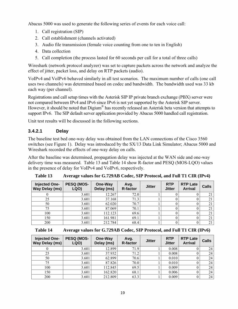
3.4.2.1 Delay
The baseline test bed one-way delay was obtained from the LAN connections of the Cisco 3560 switches (see Figure 1). Delay was introduced by the SX/13 Data Link Simulator; Abacus 5000 and Wireshark recorded the effects of one-way delay on calls.
After the baseline was determined, propagation delay was injected at the WAN side and one-way delivery time was measured. Table 13 and Table 14 show R-factor and PESQ (MOS-LQO) values in the presence of delay for VoIPv4 and VoIPv6, respectively.
Table 13 Average values for G.729AB Codec, SIP Protocol, and Full T1 CIR (IPv4)
Injected One-Way Delay (ms)
PESQ (MOS-LQO)
One-Way Delay (ms)
Avg. R-factor
Jitter RTP Jitter
RTP Late Arrival
Calls
0 3.601 12.267 72.0 1 0 0 2125 3.601 37.168 71.3 1 0 0 2150 3.601 62.020 70.7 1 0 0 2175 3.601 87.069 70.1 1 0 0 21100 3.601 112.123 69.6 1 0 0 21150 3.601 161.981 69.1 1 0 0 21200 3.601 212.784 68.4 1 0 0 21
Table 14 Average values for G.729AB Codec, SIP Protocol, and Full T1 CIR (IPv6)
Injected One-Way Delay (ms)
PESQ (MOS-LQO)
One-Way Delay (ms)
Avg. R-factor
Jitter RTP Jitter
RTP Late Arrival
Calls
0 3.601 12.899 71.9 1 0.008 0 2425 3.601 37.932 71.2 1 0.008 0 2450 3.601 62.899 70.6 1 0.010 0 2475 3.601 87.826 70.0 1 0.010 0 24100 3.601 112.845 69.5 1 0.009 0 24150 3.601 162.820 68.1 1 0.006 0 24200 3.601 212.809 63.3 1 0.009 0 24

20
The two tables above show that PESQ (MOS-LQO) is not affected by injected delay; R-factor is affected by injected delay. Table 14 shows that R-factor dropped below 71.9 when round-trip delay increased to 100 ms. In terms of estimated MOS, an R-factor of 71.9 correlates to “fair” approaching “good” (per ITU-T Recommendation G.107 Figure B.2). Thus, one-way delay should be less than 50 ms; one-way delay values above this threshold adversely affect voice quality.
3.4.2.2 Jitter
The ConNIE was used to inject jitter and Abacus 5000 was used to create voice traffic (21 to 22 calls). The VoIP test bed had an inherent jitter of 2.5 ms as measured by the Abacus 5000. The inherent RTP jitter captured by Wireshark was 3.75 ms. Wireshark measurements were recorded for two minutes. Voice quality was slightly affected when injected jitter was between 30 and 40 ms; PESQ (MOS-LQO) remained high but R-factor dropped to 70.70. Values of 70.75 and above provided good results (see Table 18) in our ad hoc audio demonstration. Abacus 5000 and Wireshark results are summarized in Table 15 and Table 16 below. The tables show that jitter measurements are virtually identical between IPv4 and IPv6 implementations.
Figure 3 shows a comparison between VoIPv4 and VoIPv6 one-way delay in the presence of injected jitter. Overall, VoIPv6 calls have a slightly higher average one-way delay in the presence of injected jitter.
Table 15 Injected Jitter IPv4 at Full T1 CIR
Injected Jitter (ms)
Avg. One- Way Delay
(ms)
PESQ (MOS-LQO)
Min. R-factor Max. RTP Jitter (ms) Jitter (ms)
ConNIE Abacus 5000 Abacus 5000 Abacus 5000 Abacus 5000 Wireshark Abacus 50000 12.232 3.601 71.70 1 3.75 2.55 17.120 3.601 71.60 2 3.43 4.510 21.000 3.601 71.35 1 4.37 12.015 26.030 3.601 71.30 1 3.34 16.520 29.210 3.601 71.20 1 3.87 21.030 38.740 3.601 70.90 1 3.37 31.540 46.310 3.601 70.70 1 3.69 41.050 52.780 3.601 70.50 3 5.14 51.5
Table 16 Injected Jitter IPv6 at Full T1 CIR
Injected Jitter (ms)
Avg. One- Way Delay
(ms)
PESQ (MOS-LQO)
Min. R-factor Max. RTP Jitter (ms) Jitter (ms)
ConNIE Abacus 5000 Abacus 5000 Abacus 5000 Abacus 5000 Wireshark Abacus 50000 12.899 3.60 71.50 1.0 2.72 3.00 5 18.435 3.60 71.40 1.5 2.96 8.50
10 23.358 3.60 71.35 1.0 4.2 11.5 15 28.084 3.60 71.10 1.0 3.24 19.5 20 33.384 3.60 71.10 1.0 3.71 22.0 30 43.424 3.60 70.75 1.5 4.30 31.0 40 53.189 3.60 70.55 3.5 4.05 41.5 50 49.693 3.60 70.40 8.5 5.08 52.0

21
IPv4 and IPv6 Comparison of Average One-Way Delay with Injected Jitter
0
10
20
30
40
50
60
0 5ms 10 ms 15 ms 20 ms 30 ms 40 ms 50 ms
ConNIE Injected Jitter
De
lay
(m
s)
IPv4 Avg. One-Way Delay
IPv6 Avg. One-Way Delay
Figure 3 IPv4 and IPv6 Comparison of Average One-Way Delay with Injected Jitter
Figure 4 below shows the relationship between injected jitter and RTP jitter (analyzed by Wireshark) for VoIPv4 and VoIPv6 calls. The results show lower maximum RTP jitter in VoIPv6 calls. This shows that QoS settings give RTP higher priority over other protocols (e.g., SIP and UDP).
Comparison of IPv4 and IPv6 Maximum RTP Jitter with Injected Jitter
3.43
3.75
4.37
3.34
3.87
5.14
3.69
3.37
2.96
2.72
4.2
4.34.05
5.08
3.71
3.24
0
1
2
3
4
5
6
0 5ms 10 ms 15 ms 20 ms 30 ms 40 ms 50 ms
ConNIE Injected Jitter
Max
imu
m R
TP
Jit
ter
(ms)
IPv4 RTP Jitter (ms) Maximum
IPv6 RTP Jitter (ms) Maximum
Figure 4 Comparison of IPv4 and IPv6 Maximum RTP Jitter with Injected Jitter

22
3.4.2.3 Injected Packet Loss
An ad hoc demonstration was conducted and subjective assessments were collected of participants’ perception of the audio quality of spoken test phrases in comparison with the measured results provided by the objective tests. As packet loss increased, R-factor declined, and based on team members’ subjective assessment, voice quality was poor (as defined in Table 18). R-factor values of 70.75 and above provided good results in our ad hoc audio demonstration. The results in Table 17 show the effects of injected packet loss on R-factor, PESQ (MOS-LQO), and subjective assessments. The first error occurred when injected packet loss level was .40% (i.e., a drop of one packet in every 250 packets).
Table 17 Effect of Injected Packet Loss on R-factor*
ConNIE Impairment (Injected Packet
Loss)**
Avg. R-factor
Avg. PESQ (MOS-LQO)
Subjective Assessment
Rating
Channels with
Errors***
0 71.90 3.601 Excellent 0 .20% 71.15 3.558 Good 0 .22% 71.05 3.562 Good 0 .25% 70.85 3.549 Good 0 .30% 70.70 3.542 Fair 0 .33% 70.60 3.537 Fair 0 .40% 70.35 3.523 Poor 2 .45% 70.00 3.507 Bad 0 .50% 70.05 3.507 Bad 0 .55% 69.85 3.498 Bad 6 .60% 70.00 3.505 Bad 2 .65% 69.25 3.466 Bad 2 .70% 69.25 3.465 Bad 2 .75% 69.00 3.454 Bad 2 .80% 68.90 3.445 Bad 2 .85% 68.70 3.434 Bad 2 .90% 68.65 3.433 Bad 6
* 22 total calls (21 Abacus and 1 from analog phone), CIR = Full T1 ** See Table 4-2 Rates of Packet Loss Injected by ConNIE *** Error is PESQ less than 3.0.
3.4.3 Integrated System
The VoIP test bed topology consists of two nodes, with each node consisting of dedicated equipment and addressing schemes, and configured in a dual-stack mode (i.e., either IPv4 or IPv6 capable) able to interface with NAS voice switch systems (VSCS, VTABS, ETVS, and IVSR). Call initiation is over IPv6 (IPv6 dial plan), call registration is over IPv4, and routing is over IPv4.
Proof of concept demonstrations were conducted from October 2008 to February 2009. VoIPv6 calls could not be demonstrated until April 2009. VoIP COTS products are not completely ready to support IPv6. Industry is working on infrastructure and codes to support VoIPv6 applications (e.g., VoIPv6 dial peer configurations were not available from Cisco prior to October 2008, and a COTS product to support external call registration in IPv6 format was not available).

23
An ad hoc demonstration was conducted and subjective assessments were collected of participants’ perception of the audio quality of voice calls placed at voice switches while SmartBits 6000B generated data traffic. Demonstration participants subjectively assessed voice quality (of a single call) across the VoIP test bed.
A basic QoS model was implemented in the VoIP test bed. The CIR was allocated as follows: 25% for data (includes 5% for signaling) and 60 % for voice traffic. Objective evaluations and subjective demonstrations showed favorable voice quality measurements using this QoS model.
Subjective demonstration of voice quality was accomplished as follows. The test conductor evaluated the objective test results. The system end users assessed call voice quality based on criteria listed in Table 18 (this rating system is based on modified industry standards). Objective assessments were correlated with the subjective assessments provided by demonstration participants.
Table 18 Subjective Assessment Rating
Rating Description Excellent Imperceptible impairments Good Perceptible impairments but still completely intelligible Fair Slightly unintelligible, some missing syllables Poor Unintelligible, missing syllables, jitter, static and echo Bad Unintelligible, constant missing syllables, delay, static and lots of echo
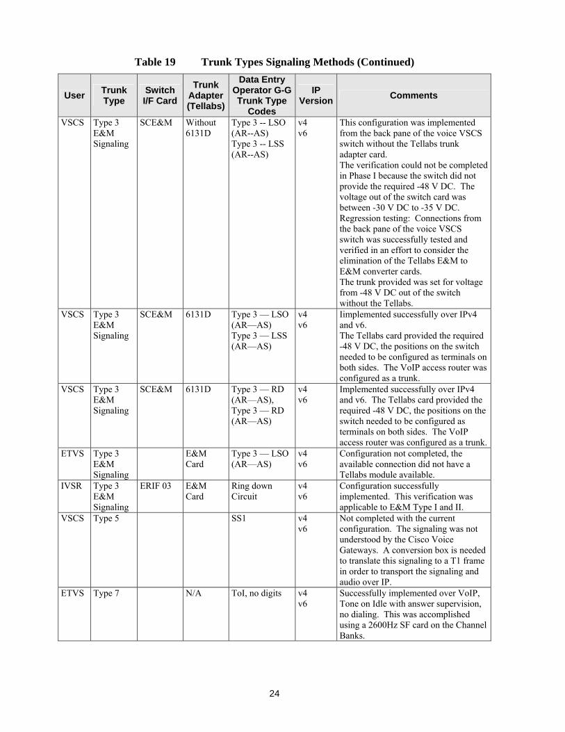
Switch trunks used were industry E&M Type 1 and 2 configured as ringdown circuits, set for 6-wire and 8-wire interfaces; Type 7 configured as Tone on Idle (ToI) and Tone on Active (ToA); Type 5 and Type 9. ETVS and IVSR use E&M cards to interface with the VoIP test bed. The VSCS switch uses a Tellabs interface card to interface with the VoIP test bed, in this case, the E&M interface cards reside within the switch. The Tellabs 6131D Module E&M-to-E&M Signaling Converter allows the VSCS to interface with various E&M arrangements. See Figure 5 for a subset of evaluated trunks.
Table 19 summarizes the interfaces that were investigated, and the resulting findings.
Table 19 Trunk Types Signaling Methods
User Trunk Type
Switch I/F Card
Trunk Adapter (Tellabs)
Data Entry Operator G-G Trunk Type
Codes
IP Version
Comments
VSCS Type 3 Loop Start Station Signaling
SCE&M 6131A Type 3 -- LSO (AR--AS)
End-user resources were not available to complete configuration.
VSCS Type 3 Loop Start Station Signaling
SCE&M 6131B Type 3 -- LSS (AR--AS)
End-user resources were not available to complete configuration.
24
Table 19 Trunk Types Signaling Methods (Continued)
User Trunk Type
Switch I/F Card
Trunk Adapter (Tellabs)
Data Entry Operator G-G Trunk Type
Codes
IP Version
Comments
VSCS Type 3 E&M Signaling
SCE&M Without 6131D
Type 3 -- LSO (AR--AS) Type 3 -- LSS (AR--AS)
v4 v6
This configuration was implemented from the back pane of the voice VSCS switch without the Tellabs trunk adapter card. The verification could not be completed in Phase I because the switch did not provide the required -48 V DC. The voltage out of the switch card was between -30 V DC to -35 V DC. Regression testing: Connections from the back pane of the voice VSCS switch was successfully tested and verified in an effort to consider the elimination of the Tellabs E&M to E&M converter cards. The trunk provided was set for voltage from -48 V DC out of the switch without the Tellabs.
VSCS Type 3 E&M Signaling
SCE&M 6131D Type 3 — LSO (AR—AS) Type 3 — LSS (AR—AS)
v4 v6
Iimplemented successfully over IPv4 and v6. The Tellabs card provided the required -48 V DC, the positions on the switch needed to be configured as terminals on both sides. The VoIP access router was configured as a trunk.
VSCS Type 3 E&M Signaling
SCE&M 6131D Type 3 — RD (AR—AS), Type 3 — RD (AR—AS)
v4 v6
Implemented successfully over IPv4 and v6. The Tellabs card provided the required -48 V DC, the positions on the switch needed to be configured as terminals on both sides. The VoIP access router was configured as a trunk.
ETVS Type 3 E&M Signaling
E&M Card
Type 3 — LSO (AR—AS)
v4 v6
Configuration not completed, the available connection did not have a Tellabs module available.
IVSR Type 3 E&M Signaling
ERIF 03 E&M Card
Ring down Circuit
v4 v6
Configuration successfully implemented. This verification was applicable to E&M Type I and II.
VSCS Type 5 SS1 v4 v6
Not completed with the current configuration. The signaling was not understood by the Cisco Voice Gateways. A conversion box is needed to translate this signaling to a T1 frame in order to transport the signaling and audio over IP.
ETVS Type 7 N/A ToI, no digits v4 v6
Successfully implemented over VoIP, Tone on Idle with answer supervision, no dialing. This was accomplished using a 2600Hz SF card on the Channel Banks.

25
Table 19 Trunk Types Signaling Methods (Continued)
User Trunk Type
Switch I/F Card
Trunk Adapter (Tellabs)
Data Entry Operator G-G Trunk Type
Codes
IP Version
Comments
VSCS Type 7 N/A ToI, no digits v4 v6
Successfully implemented over VoIP, Tone on Idle with answer supervision, no dialing. This was accomplished using a 2600Hz SF card on the Channel Banks.
VSCS Type 7 N/A ToI, with digits Not completed with the current configuration.
VSCS Type 7 N/A ToA Signaling was transported over IP, the call was established but the audio was not available. The tone needs to be filtered from the audio; this was not accomplished. The audio did not go across only the call signaling was accomplished.
VSCS Type 7 N/A ToA Signaling was transported over IP, the call was established but the audio was not available. The tone needs to be filtered from the audio; this was not accomplished. The audio did not go across only the call signaling was accomplished.
VSCS Type 9 VOX Not completed with the current configuration. The signaling was not understood by the Cisco Voice Gateways. A conversion device is needed to translate this signaling to a T1 frame in order to transport the signaling and audio over IP.
Type 7 trunks were verified using VTABS and ETVS voice switches. The trunks were set as ToI with answer supervision, no dialing. Single Frequency cards were used to detect a 2600 Hz tone and interpret that as an On-Hook or Off-Hook condition. Trunk Type 7, when configured in ToI mode, worked across the VoIP environment over a T1 connection.

26
Figure 5 NAS Switches and VoIP Network
4 Conclusions The VoIP test bed supports VoIPv4 and VoIPv6 G-G communications with current NAS voice systems. It should be noted that VoIP COTS products are not completely ready to support IPv6. Industry is working on infrastructure and codes to support VoIPv6 applications (e.g., VoIPv6 dial peer configurations were not available from Cisco prior to October 2008).
Subjective assessments were performed for Type 3 ringdown circuits, Type 3 with digits, and Type 7 (ToI) without digits (used by VSCS, VTABS, ETVS, and IVSR voice systems). The assessments were satisfactory for these voice switch trunk types implemented with VoIPv4 and VoIPv6.
Voice quality evaluations were completed in scenarios with and without impairments of delay, jitter, and packet loss. The G.729AB codec showed good performance in terms of bandwidth consumption and voice quality. The codec performed satisfactorily in presence of injected impairments. However, G.729AB would be better suited for a voice-only network. This codec is vulnerable to impairments, such as packet loss (see Table 17) and jitter (see Table 15 and Table 16).
A converged network approach can be effective only if the data traffic is well controlled (e.g., rate limiting) and if QoS is properly implemented. Otherwise, a voice-only network should be considered for NAS voice G-G communications.

27
4.1 Throughput
Network throughput varied depending on the frame size and the CIR allocated. The load placed on the WAN should not exceed the allocated bandwidth. The evaluations were completed successfully; the performance of IPv4 and IPv6 produced identical results. No frame loss was recorded; the implementation of IP services in IPv6 did not affect the performance of the network or network devices.
4.2 Delay
The analog to IP conversion required when interfacing the legacy system with VoIP will produce an inherent delay. This delay must be considered in network design since it may incur echo problems. ITU-T Recommendation G.131 states that echo cancellation should be enabled for a connection with delay in excess of 25 ms. In our findings, R-factor was affected once injected one-way delay reached 50 ms. In terms of estimated MOS, an R-factor of 71.9 correlates to “fair” approaching “good” (per ITU-T Recommendation G.107 Figure B.2). Thus, one-way delay should be less than 50 ms; one-way delay values above this threshold adversely affect voice quality.
4.3 Latency
In general, the results showed latency levels within the 150 ms one-way delay noted in ITU-T Recommendation G.114. In addition, the round-trip latency was less than 25 ms; ITU-T Recommendation G.131 states that echo cancellation be enabled for a connection with delay in excess of 25 ms. Latency measurements for data packets used in call processing and call establishment were within ITU-T recommendations.
4.4 Latency Distribution
The latency distribution of transmitted and received packets was less than 25 ms for each of the frame sizes at maximum load. This falls below the threshold noted in ITU-T Recommendation G.114.
4.5 Jitter
Voice quality was slightly affected when injected jitter was greater than 30 ms; PESQ (MOS-LQO) remained high but R-factor dropped to 70.70. Values of 70.75 and above provided good results in our ad hoc audio demonstration. Jitter measurements are virtually identical between IPv4 and IPv6 implementations.
4.6 Injected Packet Loss
As packet loss increased, R-factor declined, and based on team members’ subjective assessment, voice quality was poor (unintelligible, missing syllables, jitter, static and echo). R-factor values of 70.75 and above provided good results in our ad hoc audio demonstration. Packet loss should be less than one packet per 400 to avoid adverse effect on voice quality. Any greater rate of packet loss should be considered unacceptable.

28
5 Recommendations The Communications Team recommends the following:
Continue the evaluation of VoIPv6 integration into NAS voice communication systems.
NAS VoIP traffic should travel on a separate secure network backbone.
If a converged (voice and data) approach is selected, well-designed quality of service (QoS) and security policies must be implemented.
Follow on evaluations should demonstrate (a) additional sector communications (e.g., a third node to simulate a third site; third NAS switch), (b) communication with two other locations simultaneously, and (c) failover scenarios.
A thorough investigation of the operational call volume and bandwidth used for voice in the current FAA NAS environment should be conducted to properly design the backbone and create a baseline for VoIP QoS.
Create network requirements that include IP addressing structures and security standards to provide high levels of availability, integrity, performance, and QoS for VoIP in NAS applications.
An evaluation of the effect of security features on latency and voice quality should be conducted (e.g., security features such as Internet Protocol Security (IPsec)).
To facilitate the transition of the legacy systems into a VoIP network, COTS conversion devices are needed to convert trunk signaling to a T1 frame. For example, the selective signaling 1 (SS-1) and VOX trunk types were not handled by our current voice gateways. Additionally, COTS products should be added to improve call routing and add dialing plan refinements within the VoIP environment.
Evaluation of future NAS voice switches or VoIP services should include packet loss and jitter in test scenarios since they are conditions inherent in a real-world environment.
A true Mean Opinion Score (MOS) evaluation with Air Traffic Control (ATC) involvement should be conducted for VoIP services and codecs (e.g., G.711u-law, G726, and G.729AB).
Investigate feasibility of VoIP integration into the ground-to-ground portion of FAA air-to-ground communications systems.
A monitoring tool is needed to provide alerts and alarms when network capabilities are diminished. This will be a crucial requirement prior to fielding.
Evaluation of VoIP should be conducted in accordance with guidelines detailed in the Test and Evaluation Handbook.

29
Bibliography
Government Documents
Federal Aviation Administration. Air Traffic Organization. NextGen and Operations Planning. Systems Engineering and Safety Office. National Airspace System (NAS) Enterprise Architecture Group. Statement of Work , Section C. Washington, DC, 2006.
Federal Aviation Administration. Air Traffic Organization. NextGen and Operations Planning.
Systems Engineering and Safety Office. Implementation of Voice over Internet Protocol (VoIP) For NAS Interfacility Communications: Reference Guide Version 1.1. Washington, DC, 2005.
Federal Aviation Administration. Acquisition Management System. Content and Format of FAA
Operational Test (OT) Plans. Washington, DC, 2006 Federal Aviation Administration. Test and Evaluation Services Group. Communications Team.
Plan for the System Integration Study (SIS) of the Voice over Internet Protocol version 4 (VoIPv4) for NAS Ground-to-Ground (G-G) Communications Systems. Atlantic City: William J. Hughes Technical Center, 2007.
Federal Aviation Administration. Test and Evaluation Services Group. Communications Team.
Session Initiation Protocol (SIP) Setup Instructions for Spirent Communications Abacus 5000 IP Telephony Migration Test System for the VoIP Study. Atlantic City: William J. Hughes Technical Center, 2008.
Federal Aviation Administration. Test and Evaluation Services Group. Communications Team.
Analog Voice Switch Communications Over the IP Network for the VoIP Study. Atlantic City: William J. Hughes Technical Center, 2007.
Federal Aviation Administration. Test and Evaluation Services Group. Communications Team.
H.323 Protocol Setup Instructions for Spirent Communications Abacus 5000 IP Telephony Migration Test System for the VoIP Study. Atlantic City: William J. Hughes Technical Center, 2007.
System Maintenance Manual for the Voice Switching and Control System (VSCS). Publication no.
TI 6690.19. Atlantic City: William J. Hughes Technical Center, November 2007. VSCS to the Trunk Interface Control Document for the Voice Switching and Control System (VSCS).
Publication no. NAS-IC-42018404. Atlantic City: William J. Hughes Technical Center, 1998.
Bowen, David. “Internet Protocol Version 6 (IPv6) Guidance.” Memo to Management Board. 14 June 2006. MyFAA Employee Site. Federal Aviation Administration. Web. 27 May 2008. https://intranet.faa.gov/faaemployees/org/staffoffices/aio/library/media/FAA_IPv6_Memorandum.pdf.

30
Non-Government Documents
Transmission impairments due to speech processing. Publication no. ITU-T G.113. Geneva: International Telecommunication Union, 1996.
The E-Model, a computational model for use in transmission planning. Publication no. ITU-T
G.107. Geneva: International Telecommunication Union, 2000. One-way transmission time. Publication no. ITU-T G.114. Geneva: International
Telecommunication Union, 2003. Talker echo and its control. Publication no. ITU-T G.131. Geneva: International
Telecommunication Union, 2003. Effect of transmission impairments. Publication no. ITU-T P.11. Geneva: International
Telecommunication Union, 1993. Methods for subjective determination of transmission quality. Publication no. ITU-T P.800. Geneva:
International Telecommunication Union, 1996. Mean Opinion Score (MOS) terminology. Publication no. ITU-T P.800.1. Geneva: International
Telecommunication Union, 2006. Application guide for objective quality measurement based on Recommendations P.862, P.862.1 and
P.862.2. Publication no. ITU-T P.862.3. Geneva: International Telecommunication Union, 2005.
ConNIE - Converged Network Impairment Emulator. Mililani: NetworkFX Communications, LLC,
2006. Program documentation. Abacus 5000. Calabasas. Spirent Communications, LLC, 2005. Program documentation.

31
Abbreviations and Acronyms
A-G air-to-ground AMS Acquisition Management System AT Air Traffic ATC Air Traffic Control ATM Air Traffic Management ATO-P Air Traffic Organization - Operations Planning Avg. average b/s bits per second BWM Bandwidth Manager CIR committed interface rate codec coder-decoder CoS class of service COTS commercial, off the shelf CPE customer premises equipment CS-ACELP Conjugate-Structure Algebraic Code Excited Linear Prediction DHCP Dynamic Host Configuration Protocol DiffServ Differentiated services DNS Domain Name System E&M ear and mouth (or earth and magneto) ETVS Enhanced Terminal Voice Switch FAA Federal Aviation Administration FIRMNet FAA IP-Routed Multi-user Network fps frames per second FTI FAA Telecommunications Infrastructure FXO foreign exchange office FXS Foreign Exchange Station G-G ground-to-ground Gb/s Gigabit per second Hz hertz IP Internet Protocol IPsec Internet Protocol Security ISP internet service provider ITU-T International Telecommunications Union - Telecommunication Standardization Sector IVSR Interim Voice Switch Replacement kb/s kilobit per second LAN local area network LQO Listening Quality Objective Max. maximum Mb/s Megabit per second Min. minimum MOS Mean Opinion Score ms millisecond NAS National Airspace System OT operational test

32
PBX private branch exchange PCM Pulse-code modulation PESQ perceptual evaluation of speech quality PHB per-hop behavior PoE Power over Ethernet PPP Point-to-Point Protocol PSQM perceptual speech quality measure QoS quality of service QSIG Q Signaling protocol R-factor Rating factor RDVS Rapid Deployment Voice Switch RTCP Real-time Transport Protocol (RTP) Control Protocol RTP Real-time Transport Protocol RX receive SIP Session Initiation Protocol SIS system integration study SNMPv3 Simple Network Management Protocol version 3 SOW statement of work SS1 selective signaling 1 SUT system under test T1 1.544 Mb/s (24 user channels) TCP Transmission Control Protocol TCP/IP Transmission Control Protocol/Internet protocol ToA Tone on active ToI Tone on idle ToS Type of Service TCS Technical Center Site TX transmit UDP User Datagram Protocol UT unit test V DC volts, direct current VoIP Voice over Internet Protocol VoIPv4 Voice over Internet Protocol version 4 VoIPv6 Voice over Internet Protocol version 6 VSCS Voice Switching Control System VTABS VSCS Training and Backup System WAN wide area network