otf vacuum test - alpha magnetic spectrometer · 1 1. test objectives 1.1. the vacuum test will...
TRANSCRIPT

LMSEAT 33791
TEST PLAN FOR THE VACUUM TEST OF THE O-RING TEST FIXTURE (OTF) FOR THE
ALPHA MAGNETIC SPECTROMETER (AMS)-02
TWP MHECSMBSX
Prepared by
Lockheed Martin Space Operations Houston, TX
For
National Aeronautics and Space Administration Lyndon B. Johnson Space Center
July 18, 2002

LMSEAT 33791
i
Test Plan for the O-Ring Test Fixture
Prepared by:
Original signed by Hsing Ju on 23 Jul 2002 Hsing Ju, Test Engineer LMSO
Reviewed by:
Original signed by C. Balasubramanian on 18 Jul 2002 Chittur Balasubramanian, Stress Analysis Lead LMSO
Original signed by Phil Mott on 18 Jul 2002 Phil Mott, Certification & Test Lead LMSO Approval:
Original signed by Trent Martin on 23 Jul 2002
Trent Martin, Structural Analysis Lead LMSO
Original signed by Mike Trznadel on 31 Jul 2002 Mike Trznadel, Manager Structural Analysis Section LMSO
Original signed by Kenneth Bollweg on 31 Jul 2002 Kenneth Bollweg Project Manager, AMS-02 LMSO

LMSEAT 33791
ii
CONTENTS Section..................................................................................................................... Page
1. Test Objective..................................................................................................... 1
2. Test Overview..................................................................................................... 1
3. Test Article.......................................................................................................... 2
4. O-Ring Tests ...................................................................................................... 3
4.1. Test Case I (Vacuum Pull As Built and Data Collection) ............................ 3
4.2. Test Case II (O-Ring Leak Check) .............................................................. 4
4.3. Test Case III (Vacuum Pull after Iridite) ....................................................... 5
4.4. Test Case IV (O-Ring Leak Check).............................................................. 5
4.5. Test Case V (Long Term Leak Rate) .......................................................... 5
5. Test Instrumentation........................................................................................... 6
6. Pass/Fail Criteria ................................................................................................ 13
7. Test Support ....................................................................................................... 14
Appendix A: OTF Disassembly Procedure.............................................................. A1
Appendix B: Stress Analysis ................................................................................... B1
Appendix C: OTF Assembly Procedure .................................................................. C1
Appendix D: OTF Vacuum Hardware Assembly Procedure.................................... D1
Appendix E: OTF Conical Flange External O-Ring Leak Check Setup Procedure.. E1
Appendix F: OTF Support Ring External O-Ring Leak Check Setup Procedure .... F1
Appendix G: OTF Conical Flange Internal O-Ring Leak Check Setup Procedure . G1
Appendix H: OTF Support Ring Internal O-Ring Leak Check Setup Procedure...... H1
Appendix I: OTF System Leak Check Setup Procedure ........................................ I1
Appendix J: Vacuum Pull Procedure ...................................................................... J1
Appendix K: External Leak Check Procedure ........................................................ K1
Appendix L: Internal Leak Check Procedure .......................................................... L1
Appendix M: System Leak Check Procedure ......................................................... M1
Appendix N: Long Term Leak Rate Procedure ...................................................... N1
Appendix O: Procedure for Swagelok Tube Fittings ............................................... O1

LMSEAT 33791
iii
Appendix P: Vacuum Gauge Measurement Uncertainty......................................... P1

LMSEAT 33791
iv
TABLES
Table Page
5.1-1 Summary of Strain and Deflection Gages................................................ 7
5.2-1 Material Properties for Strain Gage Setup ............................................... 8
5.3-1 Deflection Gage Summary....................................................................... 8
7.1 OTF Review Board .................................................................................. 14
FIGURES
Figure Page
3-1 O-Ring Test Fixture (OTF) ....................................................................... 2
4.1 Vacuum Test Hardware ........................................................................... 3
5.4-1 Gage Setup, Front View........................................................................... 10
5.4-2 Gage Setup, Top View............................................................................. 11
5.4-3 Gage Setup, Section View ....................................................................... 12

LMSEAT 33791
v
ACRONYMS AND ABBREVIATIONS
AMS Alpha Magnetic Spectrometer
FEM Finite Element Model
JSC Johnson Space Center
LBB Leak Before Burst
LMSO Lockheed Martin Space Operations
MSDS Material Safety Data Sheet
OTF O-Ring Test Fixture
P/N Part Number
QA Quality Assurance
STL Structural Testing Laboratory
TPS Task Preparation Sheet
TRR Test Readiness Review

LMSEAT 33862
1
1. Test Objectives
1.1. The vacuum test will verify that the current O-Ring groove configuration will seal at 1 x 10⁻⁶ torr.
1.2. The vacuum test will determine the short term and long term leak rate of the OTF.
1.3. The vacuum test will verify procedures used for O-Ring seal integrity on the OTF are adequate. The same procedures will be used on the Flight Vacuum Case.
1.4. Yielding of the OTF is not expected at a vacuum of 1 x10⁻⁶ torr. Pretest analysis has been performed and is attached as Appendix A of this document.
1.5. The vacuum test will verify that the iriditing process will not outgas when applied to the internal surfaces of the OTF.
1.6. Strain and deflection data will be taken during the first test. This data will be used to verify the FEM of the OTF.
2. Test Overview The vacuum test of the OTF will consist of five individual test cases. The first test case will determine if the OTF can reach the required vacuum level (1 x 10⁻⁶ torr) in the as built configuration. There are several scratches across the main o-ring grooves due to previous improper handling for the positive pressure test and performing this test will help determine how much groove damage can be tolerated before repair is necessary. Strain and deflection data will also be collected during this test for FEM verification. A hard vacuum of 1 x 10⁻⁶ torr is not required for the data collection as long as a vacuum is achieved. A vacuum of approximately 1 x 10⁻² torr is sufficient but the Test Engineer will make a final determination during the test. If the required vacuum can be reached, then the OTF will proceed to test case 2. If the required vacuum cannot be reached, then the OTF will need to be repaired. After the repairs, the first test case will be repeated to insure that the required vacuum of 1 x 10⁻⁶ torr can be reached. The second test case will consist of leak checks on both the individual O-Rings and the system. This test case will leak check all the large O-rings using a helium leak detector. This test will also determine the leak rate of the OTF. The third test case, which is similar to the first, will determine if the OTF will experience any outgassing problems due to the iridite process. An outside vendor will perform the iridite process and the time frame between test case 2 and 3

LMSEAT 33862
will be about one month. The fourth test case will consist of leak checks on both the individual O-Rings and the system as in test case 2. This test will also determine the leak rate of the OTF with the iridited internal surfaces. Test case 5 will be a long-term vacuum test. The OTF will be sealed and set aside. Pressure will be checked on a daily basis for the first few weeks and then on a weekly basis to determine long-term leak rates.
3. Test Article The test article consists of one Class III OTF, P/N SEG36144341-301, and is shown in Figure 3-1.
CONICAL FLANGESIMLATOR
SUPPORT RINGSIMULATOR
VACUUM PORT
OUTER CYLINDERSIMULATOR
PRESSUREPORT
LEAK CHECKPORT (2X)
CONICAL FLANGESIMLATOR
SUPPORT RINGSIMULATOR
VACUUM PORT
OUTER CYLINDERSIMULATOR
PRESSUREPORT
LEAK CHECKPORT (2X)
Figure 3-1: O-Ring Test Fixture (OTF)
2

LMSEAT 33862
4. O-Ring Tests Figure 4-1 shows the generic test setup for the OTF with the pneumatically actuated gate valve and turbomolecular vacuum pump.
O-Ring TestFixture
TurbomolecularVacuum Pump
PneumaticallyActuatedGate Valve
O-Ring TestFixture
TurbomolecularVacuum Pump
PneumaticallyActuatedGate Valve
Figure 4-1: Vacuum Test Hardware
4.1. Test Case I (Vacuum Pull As Built and Data Collection)
4.1.1. Disassemble OTF per Appendix B.
4.1.2. Remove OXSOL-100 protective coating on the Conical Flange by hand only. The personnel removing the coating must wear lint-free latex gloves. Clean the area that the OXSOL-100 protected with Isopropyl Alcohol, Reagent Grade, along with lint free cloths to remove any coating residue.
4.1.3. Assemble the OTF per Appendix C.
4.1.4. Place the assembled OTF on the support frame supplied by the AMS project. The frame will support the entire
3

LMSEAT 33862
4
circumference of the Outer Cylinder Simulator while allowing the OTF to deflect without affecting the results.
4.1.5. Assemble vacuum hardware per Appendix D.
4.1.6. Connect gages and setup data acquisition system per section 4.
4.1.7. Perform test per TPS. (Procedures overview can be found in Appendix J)
4.1.8. Disassemble OTF or continue Test per AMS-02 test engineer’s instruction.
4.2. Test Case II (O-Ring Leak Check)
4.2.1. If OTF was disassembled in 4.1.8, assemble OTF per Appendix C.
4.2.2. Reconfigure hardware for Conical Flange external O-Ring leak check per Appendix E.
4.2.3. Perform leak check per TPS. (Procedures overview can be found in Appendix K)
4.2.4. Reconfigure hardware for Support Ring external O-Ring leak check per Appendix F.
4.2.5. Perform leak check per TPS. (Procedures overview can be found in Appendix K)
4.2.6. Reconfigure hardware for Conical Flange internal O-Ring leak check per Appendix G.
4.2.7. Perform leak check per TPS. (Procedures overview can be found in Appendix L)
4.2.8. Reconfigure hardware for Support Ring internal O-Ring leak check per Appendix H.
4.2.9. Perform leak check per TPS. (Procedures overview can be found in Appendix L)
4.2.10. Reconfigure hardware for system leak check per Appendix I.

LMSEAT 33862
5
4.2.11. Perform leak check per TPS. (Procedures overview can be found in Appendix M)
4.2.12. Disassemble OTF or continue Test per AMS-02 test engineer’s instruction.
4.3. Test Case III (Vacuum Pull after Iridite)
4.3.1. IF OTF was disassembled, assemble OTF per Appendix C.
4.3.2. The OTF will be supported around the entire circumference of the Outer Cylinder Simulator by a wood frame. This will allow the OTF to deflect without affecting the results.
4.3.3. Setup vacuum hardware per Appendix D.
4.3.4. Perform test per TPS. (Procedures overview can be found in Appendix J)
4.4. Test Case IV (O-Ring Leak Check)
4.4.1. If OTF did not reach 1x10⁻⁶ torr in Section 4.3 perform leak checks per section 4.2
4.5. Test Case V (Long Term Leak Rate)
4.5.1. Perform test per TPS. (Procedures overview can be found in Appendix N)

LMSEAT 33862
6
5. Test Instrumentation
5.1. Gages
The OTF will require the following instrumentation (see Table 5.1-1 for a list of gages):
• 11 Deflection gages • 4 Triaxial Strain gages • 1 Uniaxial gage • 1 Pressure gauge
The strain gages have already been installed for the positive pressure test and only need to be connected. Building 33 personal my use building 13 personal for any or all gage setups. This instrumentation will only be needed on Test Case 1 (Section 4.1).
LMSEAT 33862
7
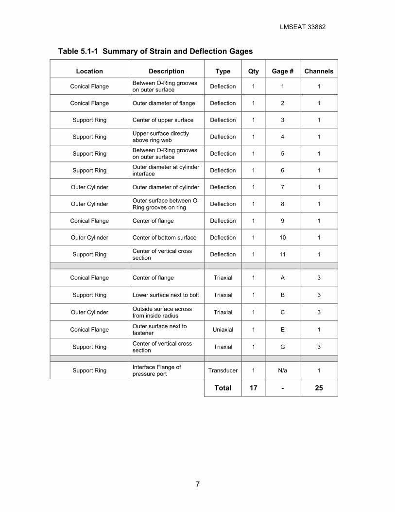
Table 5.1-1 Summary of Strain and Deflection Gages
Location
Description
Type Qty
Gage #
Channels
Conical Flange Between O-Ring grooves on outer surface Deflection 1 1 1
Conical Flange Outer diameter of flange Deflection 1 2 1
Support Ring Center of upper surface Deflection 1 3 1
Support Ring Upper surface directly above ring web Deflection 1 4 1
Support Ring Between O-Ring grooves on outer surface Deflection 1 5 1
Support Ring Outer diameter at cylinder interface Deflection 1 6 1
Outer Cylinder Outer diameter of cylinder Deflection 1 7 1
Outer Cylinder Outer surface between O-Ring grooves on ring Deflection 1 8 1
Conical Flange Center of flange Deflection 1 9 1
Outer Cylinder Center of bottom surface Deflection 1 10 1
Support Ring Center of vertical cross section Deflection 1 11 1
Conical Flange Center of flange Triaxial 1 A 3
Support Ring Lower surface next to bolt Triaxial 1 B 3
Outer Cylinder Outside surface across from inside radius Triaxial 1 C 3
Conical Flange Outer surface next to fastener Uniaxial 1 E 1
Support Ring Center of vertical cross section Triaxial 1 G 3
Support Ring Interface Flange of pressure port Transducer 1 N/a 1
Total 17 - 25
LMSEAT 33862
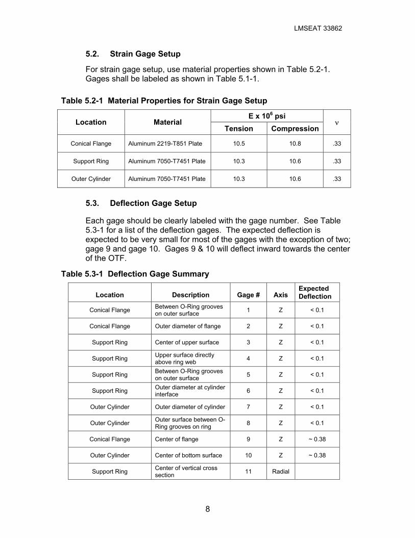
5.2. Strain Gage Setup
For strain gage setup, use material properties shown in Table 5.2-1. Gages shall be labeled as shown in Table 5.1-1.
Table 5.2-1 Material Properties for Strain Gage Setup
E x 106 psi Location Material
Tension Compression ν
Conical Flange Aluminum 2219-T851 Plate 10.5 10.8 .33
Support Ring Aluminum 7050-T7451 Plate 10.3 10.6 .33
Outer Cylinder Aluminum 7050-T7451 Plate 10.3 10.6 .33
5.3. Deflection Gage Setup
Each gage should be clearly labeled with the gage number. See Table 5.3-1 for a list of the deflection gages. The expected deflection is expected to be very small for most of the gages with the exception of two; gage 9 and gage 10. Gages 9 & 10 will deflect inward towards the center of the OTF.
Table 5.3-1 Deflection Gage Summary
Location
Description
Gage #
Axis Expected Deflection
Conical Flange Between O-Ring grooves on outer surface 1 Z < 0.1
Conical Flange Outer diameter of flange 2 Z < 0.1
Support Ring Center of upper surface 3 Z < 0.1
Support Ring Upper surface directly above ring web 4 Z < 0.1
Support Ring Between O-Ring grooves on outer surface 5 Z < 0.1
Support Ring Outer diameter at cylinder interface 6 Z < 0.1
Outer Cylinder Outer diameter of cylinder 7 Z < 0.1
Outer Cylinder Outer surface between O-Ring grooves on ring 8 Z < 0.1
Conical Flange Center of flange 9 Z ~ 0.38
Outer Cylinder Center of bottom surface 10 Z ~ 0.38
Support Ring Center of vertical cross section 11 Radial
8

LMSEAT 33862
9
5.4. Gage Configuration
Configure gages per Figures 5.4-1 - 5.4-3. Relocation of some gages might be necessary due to the distance between the edge of the test article and the sensors. Relocation will only be necessary if a gage has been damaged during transportation and setup. STL and AMS personnel will need to agree upon the placement of the relocated sensors for practicality of the location and usefulness of the data that will be collected.

LMSEAT 33862
10
Figure 5.4-1: Gage Setup, Front View

LMSEAT 33862
11
Figure 5.4-2: Gage Setup, Top View

LMSEAT 33862
Figure 5.4-3: Gage Setup, Section View
12

LMSEAT 33791
6. Pass/Fail Criteria This is an engineering evaluation test to determine the leak rate of the OTF system. If the OTF system cannot reach a vacuum of 1 x 10⁻⁶ torr, the hardware will be modified in order to improve the sealing capabilities of the O-rings.
13
LMSEAT 33791
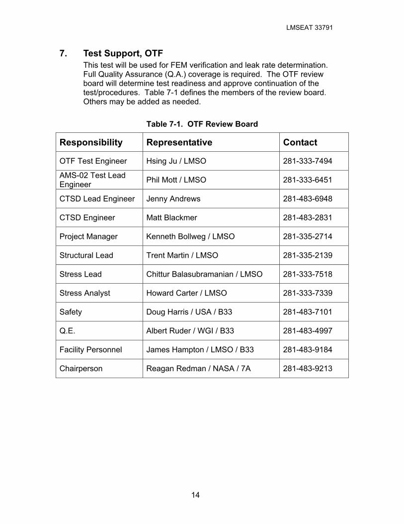
7. Test Support, OTF This test will be used for FEM verification and leak rate determination. Full Quality Assurance (Q.A.) coverage is required. The OTF review board will determine test readiness and approve continuation of the test/procedures. Table 7-1 defines the members of the review board. Others may be added as needed.
Table 7-1. OTF Review Board
Responsibility Representative Contact
OTF Test Engineer Hsing Ju / LMSO 281-333-7494
AMS-02 Test Lead Engineer Phil Mott / LMSO 281-333-6451
CTSD Lead Engineer Jenny Andrews 281-483-6948
CTSD Engineer Matt Blackmer 281-483-2831
Project Manager Kenneth Bollweg / LMSO 281-335-2714
Structural Lead Trent Martin / LMSO 281-335-2139
Stress Lead Chittur Balasubramanian / LMSO 281-333-7518
Stress Analyst Howard Carter / LMSO 281-333-7339
Safety Doug Harris / USA / B33 281-483-7101
Q.E. Albert Ruder / WGI / B33 281-483-4997
Facility Personnel James Hampton / LMSO / B33 281-483-9184
Chairperson Reagan Redman / NASA / 7A 281-483-9213
14

LMSEAT 33791
Appendix A: OTF Disassembly Procedure Note: Unless otherwise specified, personnel working on the disassembly of the OTF should wear lint free latex gloves to minimize contamination of the interfaces. 1. Remove flanges, P/N SDG36144345-001 and –005, from the OTF. Place
the flanges, P/N SDG36144345-001 and –005, into separate plastic bags. Place the bolts into another set of plastic bags. Remove the O-Ring in the O-Ring grooves of the flanges and place them into separate plastic bags to prevent contamination.
2. Remove the Conical Flange Simulator, P/N SDG36144342-001, from the Support Ring Simulator, P/N SEG36144343-301. Place the Conical Flange Simulator, P/N SDG36144342-001, with the O-Ring grooves facing up to the side. The personnel should wear lint free glove to prevent contamination of the internal surface of the OTF, P/N SEG36144341-301. Seal the O-Ring grooves on the Conical Flange Simulator, P/N SDG36144342-001, with Kapton tape after removal to minimize contamination and damage. Place the bolts into another set of plastic bag.
3. Remove O-Rings SLG36144346-001 and –003 from the dovetail O-Ring grooves and place the O-Rings into a plastic bag to prevent contamination. Do not damage the surface of the O-Ring grooves when removing the O-Rings. Seal O-Ring grooves on the Support Ring Simulator assembly, P/N SEG36144343-301, with Kapton tape after O-Ring removal to minimize contamination and damage.
4. Remove the strain gage and associated wires that are located inside the outer cylinder, P/N SEG36144344-301. The personnel should wear lint free gloves to prevent contamination of the internal surface of the Outer Cylinder, P/N SEG36144344-301.
5. After the removal of the internal strain gage, clean the contact area of the strain gage using Isopropyl Alcohol, Reagent Grade, with lint free cloth to remove strain gage adhesive. Wipe the surface clean with lint free cloth and clean up any spills that are inside the OTF.
6. Remove Support Ring Simulator, P/N SEG36144343-301, from the Outer Cylinder Simulator, P/N SEG36144344-301. Place the bolts and nuts into a plastic bag. Place the Support Ring Simulator, P/N SEG36144343-301, on a clean sheet of paper with the O-Ring grooves that mate with the Outer Cylinder, P/N SEG36144344-301, facing up.
7. Remove O-Rings SLG36144346-005 and –007 from the dovetail O-Ring groove and place the O-Rings into a plastic bag to prevent contamination. Seal O-Ring groove with Kapton tape after O-Ring removal to prevent contamination.
8. Seal the mating surface on the Outer Cylinder Simulator, P/N SEG36144344-301, with Kapton tape to minimize contamination and damage.
A1

LMSEAT 33791
Appendix B: Stress Analysis
C1

LMSEAT 33791
Appendix C: OTF Assembly Procedure Note: Unless otherwise specified, personnel working on the disassembly of the OTF should wear lint free latex gloves to minimize contamination of the interfaces. 1. Remove Kapton tape from the mating surface of the Support Ring Simulator
assembly, P/N SEG36144343-301, and the Outer Cylinder Simulator assembly, P/N SEG36144344-301. Clean the mating surface of the Outer Cylinder Simulator assembly with Isopropyl Alcohol, Reagent Grade, to remove any corrosion, tape adhesive, and vacuum grease. Also clean the exposed O-Ring grooves of the Support Ring Simulator assembly, P/N SEG36144343-301, with Isopropyl Alcohol, Reagent Grade, to remove any corrosion, tape adhesive, and vacuum grease.
2. Wearing lint free gloves, remove 1 O-Ring, P/N SLG36144346-005, from the pouch and apply a thin coat of High Vacuum Grease, P/N 1597418, to the O-Ring by squeezing some of the grease from the tube into the palm of the glove and pulling the O-Ring through the grease. The grease should evenly coat the O-Ring. Make sure that the O-Ring does not come in contact with other surfaces during the application of High Vacuum Grease. After the application of the High Vacuum Grease, place O-Ring into the smaller O-Ring groove on the Support Ring Simulator assembly, P/N SEG36144343-301.
3. Repeat the previous step except remove 1 O-Ring, P/N SLG144346-007, from the pouch and install in the larger O-Ring groove of the Support Ring Simulator assembly, P/N SEG36144343-301.
4. Dispose of excess grease and soiled gloves per the Material Safety Data Sheet (MSDS).
5. Carefully wipe off any grease from the surfaces outside of the O-Rings using Isopropyl Alcohol, Reagent Grade, with lint free cloths. The area between the O-Rings should be left alone unless there is a glob of grease on the surface (This will be determined by the test engineer). Do not touch any part of the O-Rings during the cleaning procedure. Clean as close as possible to the O-Rings without touching them.
6. Remove Kapton tape from the mating surface of the Outer Cylinder Simulator assembly, P/N SEG36144344-301. Clean the mating surface of the Outer Cylinder Simulator with Isopropyl Alcohol, Reagent Grade, along with lint free cloth to remove any corrosion, tape adhesive, and vacuum grease.
7. Install the Support Ring Simulator assembly, SEG36144343-301, to the Outer Cylinder Simulator assembly, SEG3614344-301, using 24 .250-28UNRF-3A 1.25-inch long fasteners, P/N NAS1351N4H20 and .250-28UJF-3B nuts, P/N NAS1291C4M. During the installation process, do not slide the O-Ring groove surface on the Support Ring Simulator assembly, P/N SEG36144343-301, across the mating surface of the Outer Cylinder Simulator assembly, SEG36144344-301. Install the nuts and the screws in
C1

LMSEAT 33791
a crisscross pattern to insure even O-Ring compression. Measure and record the running torque for each fastener. Final torque is 65-75 in-lbs above running torque.
8. Remove Kapton tape from the mating surface of the Support Ring Simulator assembly, P/N SEG36144343-301, and the Conical Flange Simulator assembly, P/N SDG36144342-001. Clean the mating surface of the Support Ring Simulator with Isopropyl Alcohol, Reagent Grade, to remove any corrosion, tape adhesive, and vacuum grease. Also clean the exposed O-Ring grooves of the Support Ring Simulator assembly, P/N SEG36144343-301, with Isopropyl Alcohol, Reagent Grade, to remove any corrosion, tape adhesive, and vacuum grease.
9. Wearing lint free gloves, remove 1 O-Ring, P/N SLG36144346-001, from the pouch and apply a thin coat of High Vacuum Grease, P/N 1597418, to the O-Ring by squeezing some of the grease from the tube into the palm of the glove and pulling the O-Ring through the grease. The grease should evenly coat the O-Ring. Make sure that the O-Ring does not come in contact with other surfaces during the application of High Vacuum Grease. After the application of the High Vacuum Grease, place O-Ring into the smaller O-Ring groove on the Support Ring Simulator assembly, P/N SEG36144343-301.
10. Repeat the previous step except remove 1 O-Ring, P/N SLG144346-003, from the pouch and install in the larger O-Ring groove of the Support Ring Simulator assembly, P/N SEG36144343-301.
11. Dispose of excess grease and soiled gloves per the Material Safety Data Sheet (MSDS).
12. Carefully wipe off any grease from the surfaces outside of the O-Rings using Isopropyl Alcohol, Reagent Grade, with lint free cloths. The area between the O-Rings should be left alone unless there is a glob of grease on the surface (This will be determined by the test engineer). Do not touch any part of the O-Rings during the cleaning procedure. Clean as close as possible to the O-Rings without touching them.
13. Remove Kapton tape from the mating surface of the Conical Flange Simulator, P/N SDG36144342-001. Clean the mating surface of the Conical Flange Simulator with Isopropyl Alcohol, Reagent Grade, to remove corrosion, tape adhesive, and vacuum grease.
14. Install the Conical Flange Simulator, P/N SDG36144342-001, to the Support Ring Simulator assembly, P/N SEG3614343, using 24 .250-28UNRF-3A 1-inch long fasteners, P/N NAS1351N4H16. During the installation process, do not slide the O-Ring groove surface on the Conical Flange Simulator, P/N SDG36144342-001, across the mating surface of the Support Ring Simulator assembly, SEG36144343-301. Install the nuts and the screws in a crisscross pattern to insure even O-Ring compression. Measure and record the running torque for each fastener. Final torque is 65-75 in-lbs above running torque
15. Seal all leak check ports with a hollow hex plug, P/N 2 HP5ON SS V0894. Torque hex plug 30-33 in-lbs from finger tight.
C2

LMSEAT 33791
16. Cover open feed thru ports with Kapton tape to minimize contamination of the OTF.
C3
LMSEAT 33791
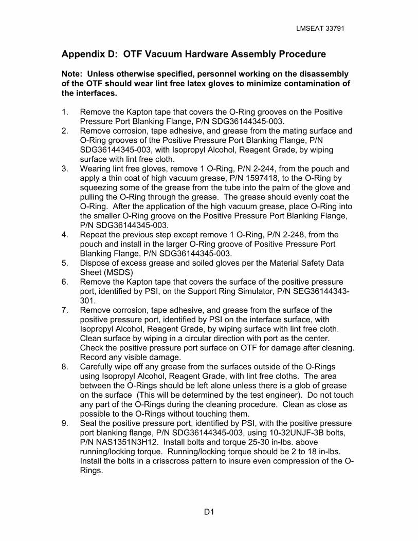
Appendix D: OTF Vacuum Hardware Assembly Procedure Note: Unless otherwise specified, personnel working on the disassembly of the OTF should wear lint free latex gloves to minimize contamination of the interfaces. 1. Remove the Kapton tape that covers the O-Ring grooves on the Positive
Pressure Port Blanking Flange, P/N SDG36144345-003. 2. Remove corrosion, tape adhesive, and grease from the mating surface and
O-Ring grooves of the Positive Pressure Port Blanking Flange, P/N SDG36144345-003, with Isopropyl Alcohol, Reagent Grade, by wiping surface with lint free cloth.
3. Wearing lint free gloves, remove 1 O-Ring, P/N 2-244, from the pouch and apply a thin coat of high vacuum grease, P/N 1597418, to the O-Ring by squeezing some of the grease from the tube into the palm of the glove and pulling the O-Ring through the grease. The grease should evenly coat the O-Ring. After the application of the high vacuum grease, place O-Ring into the smaller O-Ring groove on the Positive Pressure Port Blanking Flange, P/N SDG36144345-003.
4. Repeat the previous step except remove 1 O-Ring, P/N 2-248, from the pouch and install in the larger O-Ring groove of Positive Pressure Port Blanking Flange, P/N SDG36144345-003.
5. Dispose of excess grease and soiled gloves per the Material Safety Data Sheet (MSDS)
6. Remove the Kapton tape that covers the surface of the positive pressure port, identified by PSI, on the Support Ring Simulator, P/N SEG36144343-301.
7. Remove corrosion, tape adhesive, and grease from the surface of the positive pressure port, identified by PSI on the interface surface, with Isopropyl Alcohol, Reagent Grade, by wiping surface with lint free cloth. Clean surface by wiping in a circular direction with port as the center. Check the positive pressure port surface on OTF for damage after cleaning. Record any visible damage.
8. Carefully wipe off any grease from the surfaces outside of the O-Rings using Isopropyl Alcohol, Reagent Grade, with lint free cloths. The area between the O-Rings should be left alone unless there is a glob of grease on the surface (This will be determined by the test engineer). Do not touch any part of the O-Rings during the cleaning procedure. Clean as close as possible to the O-Rings without touching them.
9. Seal the positive pressure port, identified by PSI, with the positive pressure port blanking flange, P/N SDG36144345-003, using 10-32UNJF-3B bolts, P/N NAS1351N3H12. Install bolts and torque 25-30 in-lbs. above running/locking torque. Running/locking torque should be 2 to 18 in-lbs. Install the bolts in a crisscross pattern to insure even compression of the O-Rings.
D1

LMSEAT 33791
10. Remove the Kapton tape that covers the surface of the vacuum port, identified by VAC, on the Support Ring Simulator, P/N SEG36144343-301.
11. Remove corrosion, tape adhesive, and grease from the mating surface vacuum port with Isopropyl Alcohol, Reagent Grade, by wiping surface with lint free cloth.
12. Install NW80 centering ring, P/N 810008, and NW80 LF to NW40 KF reducing cross, P/N MSPB1260, to the chamber using NW80 rotatable bolt ring, P/N 824043, and 8 M8 X 1.25 X 30L bolts with washer, P/N 854021. Orient the reducing cross so that the cross is parallel to the ground. Net torque is 7 to 10 ft-lbs per manufacturer’s recommendation. Running/locking should be 7.5-80 in-lbs. Install the bolts in a crisscross pattern to ensure even compression of the O-Rings.
13. Install the NW80 centering ring, P/N 810008, and electropneumatic gate valve, P/N 307004, to the NW80 LF to NW40 KF reducing cross, P/N MSPB1260, using NW80 rotatable bolt ring, P/N 824043, and 8 M8 X 1.25 X 30L bolts with washer, P/N 854021. Net torque is 7 to 10 ft-lbs per manufacturer’s recommendation. Running/locking should be 7.5-80 in-lbs. Install the bolts in a crisscross pattern to ensure even compression of the O-Rings. Support the Gate Valve after assembly to prevent damage to the OTF.
14. Install 1 copper gasket, P/N 191017, and NW80 LF to DN160 CF conical adapter, P/N MSPB1286, to the Leybold AG Turbovac 361 model 85673 provided by the B33 Test Facility using 20 .312-24 x 2.9L 12 point bolt w/ washer, P/N 190045. Net torque is 15 ft-lbs per manufacturer’s recommendation. Running/locking should be 7.5-80 in-lbs. Install the bolts in ¼ to ½ turn increments in a crisscross pattern to ensure even compression of the copper gasket.
15. Install NW80 centering ring, P/N 810008, and NW80 LF to NW40 KF reducing tee, P/N 824043, to the electropneumatic gate valve, P/N 307004, using 8 single claw clamps, P/N 801000. Net torque is 7 to 10 ft-lbs per manufacturer’s recommendation. Running/locking should be 7.5-80 in-lbs. Install the bolts in a crisscross pattern to ensure even compression of the O-Rings.
16. Position the vacuum pump system next to OTF, SEG36144341-301. 17. Connect the NW80 LF to DN160 CF conical adapter, P/N MSPB1286, to the
NW80 LF to NW40 KF reducing tee, P/N 824043, using a NW80 centering ring, P/N 810008, and 8 double claw clamps, P/N 802000. Install claw clamps per manufacturer’s instructions. Net torque is 7 to 10 ft-lbs per manufacturer’s recommendation. Running/locking should be 7.5-80 in-lbs. Install the bolts in a crisscross pattern to insure even compression of the O-Rings.
18. Support the vacuum hardware if needed to prevent damage to the OTF. 19. Install PR35 Penningvac Sensor, P/N 157 51, to an open port on the NW80
LF to NW40 KF reducing cross, P/N MSPB1260, using one NW40 centering ring, P/N 71002, and one NW40 hinged clamp, P/N 701002. Tighten wing
D2

LMSEAT 33791
nut until there is metal contact between the centering ring and the mating surface
20. Connect the CM31 Combivac vacuum gauge, P/N 157 89, to the PR35 Penningvac sensor, P/N 157 51, with the 5-meter Penningvac cable, P/N 162 88.
21. Connect air supply and electric cord to the gate valve. Air supplied to valve needs to be cleaned with a filter of 40 microns capability.
22. Seal all unused NW40 ports with a NW40 centering ring, P/N 710002; NW40 blanking flange, P/N 712002;and a NW40 hinged clamps, P/N 701002. Tighten wing nut until there is metal contact between the centering ring and the mating surface.
POSITIVEPRESSURE PORTBLANKING FLANGE
O-RINGP/N 2-244
O-RINGP/N 2-248
O-RINGTEST FIXTURE
NW80 CENTERINGRING
REDUCINGCROSS
NW80 ROTATABLEBOLT RING
NW40 CENTERINGRING
HINGECLAMP
NW40 BLANKINGFLANGE
GATEVALVE
VACUUMGAGE
SINGLE CLAWCLAMP
DOUBLE CLAWCLAMP
REDUCINGTEE
CONICALREDUCER
COPPERGASKET
TURBO MOLECULARPUMP
D3

LMSEAT 33791
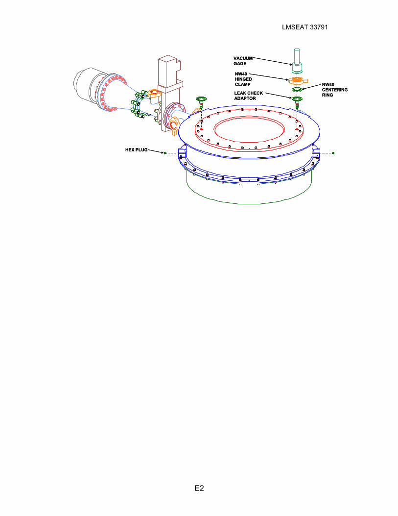
Appendix E: OTF Conical Flange External O-Ring Leak Check Setup Procedure
1. Remove the hollow hex plugs, P/N 2 HP5ON SS V0894, from the Conical
Flange Simulator, SDG36144342-001. 2. Install Leak Check Adaptor, P/N SEG36144347-301 to both test ports on
the Conical Flange Simulator, SDG36144342-001. Inspect NPT port and nipple to ensure that threads are free of nicks, burrs, and dirt. Screw adaptor into female port to the finger tight position. Torque adapter 6-7 ft-lbs from finger tight.
3. Attach flex hose, P/N KLB01503600, to the leak check adaptor, SEG36144347-301, and the NW40 to NW25 adapter, P/N KRS2540S, with NW40 centering rings, P/N 710002, and NW40 hinged clamps, P/N 701002. Tighten wing nut until there is metal contact between the centering ring and the mating surface.
4. Attach the NW40 to NW25 adapter, P/N KRS2540S, to the helium leak detector with NW25 centering rings and NW25 hinged clamps. Tighten wing nut until there is metal contact between the centering ring and the mating surface.
5. Install hollow hex plug, P/N 2 HP5ON SS V0894, on the test ports of the Support Ring Simulator Assembly, SEG36144344-301. Inspect NPT port and nipple to ensure that threads are free of nicks, burrs, and dirt. Screw hex plug into female port to the finger tight position. Torque hex plug 30-33 in-lbs from finger tight.
6. Attach the PR35 PenningVac sensor, P/N 157 51, to the other leak check adaptor, SEG36144347-301, with NW40 centering rings, P/N 710002, and NW40 hinged clamps, P/N 701002. Tighten wing nut until there is metal contact between the centering ring and the mating surface.
7. Bag the interface between the Conical Flange Simulator, SDG36144342-001, and the Support Ring Simulator assembly, SEG36144343-301, with plastic bags.
8. Attach the helium source to the plastic bags 9. Seal leakage areas of the plastic bag with duct tape to minimize helium
leaks.
E1
LMSEAT 33791
LEAK CHECKADAPTOR
HEX PLUG
NW40CENTERINGRING
NW40HINGEDCLAMP
VACUUMGAGE
LEAK CHECKADAPTOR
HEX PLUG
NW40CENTERINGRING
NW40HINGEDCLAMP
VACUUMGAGE
E2

LMSEAT 33791
Appendix F: OTF Outer Cylinder External O-Ring Leak Check Setup Procedure
1. Remove the hollow hex plugs, P/N 2 HP5ON SS V0894, from the Support Ring
Simulator Assembly, SEG36144343-301. 2. Install Leak Check Adaptor, P/N SEG36144347-301 to both test ports on the
Support Ring Simulator Assembly, SEG36144343-301. Inspect NPT port and nipple to ensure that threads are free of nicks, burrs, and dirt. Screw adaptor into female port to the finger tight position. Torque adapter 6-7 ft-lbs from finger tight.
3. Attach flex hose, P/N KLB01503600, to the leak check adaptor, SEG36144347-301, and the NW40 to NW25 adapter, P/N KRS2540S, with NW40 centering rings, P/N 710002, and NW40 hinged clamps, P/N 701002. Tighten wing nut until there is metal contact between the centering ring and the mating surface.
4. Attach the NW40 to NW25 adapter, P/N KRS2540S, to the helium leak detector with NW25 centering rings and NW25 hinged clamps. Tighten wing nut until there is metal contact between the centering ring and the mating surface.
5. Install hollow hex plug, P/N 2 HP5ON SS V0894, on the test ports of the Conical Flange Simulator, SEG36144343-301. Inspect NPT port and nipple to ensure that threads are free of nicks, burrs, and dirt. Screw hex plug into female port to the finger tight position. Torque hex plug 30-33 in-lbs from finger tight.
6. Attach the PR35 PenningVac sensor, P/N 157 51, to the other leak check adaptor, SEG36144347-301, with NW40 centering rings, P/N 710002, and NW40 hinged clamps, P/N 701002. Tighten wing nut until there is metal contact between the centering ring and the mating surface.
7. Bag the interface between the Conical Flange Simulator, SDG36144342-001, and the Support Ring Simulator assembly, SEG36144343-301, with plastic bags.
8. Attach the helium source to the plastic bags 9. Seal leakage areas of the plastic bag with duct tape to minimize helium leaks.
LEAK CHECKADAPTOR
HEX PLUG
NW40CENTERINGRING
NW40 HINGEDCLAMP
VACUUMGAGE
LEAK CHECKADAPTOR
HEX PLUG
NW40CENTERINGRING
NW40 HINGEDCLAMP
VACUUMGAGE
F1

LMSEAT 33791
Appendix G: OTF Conical Flange Internal O-Ring Leak Check Setup Procedure
1. Remove the PR35 Penningvac vacuum gauge, P/N 157 89, the flex hose,
and the leak check adaptor, P/N SEG36144347-301, from the OTF. 2. Remove NW40 blank flanges, P/N 712002, from both port of the NW80 LF
to NW40 KF reducing cross, P/N MSPB1260. Install the PR35 Penningvac vacuum gauge to an open port with a NW40 centering rings, P/N 710002, and a NW40 hinged clamps, P/N 701002. Tighten wing nut until there is metal contact between the centering ring and the mating surface.
3. Install the NW40 KF to NW25 KF conical reducer, P/N KRC2540S to the open NW40 port on the NW80 to NW40 KF reducing cross, P/N MSPB1260 with a NW40 centering rings, P/N 710002 and a NW40 hinged clamps, P/N 701002. Tighten wing nut until there is metal contact between the centering ring and the mating surface.
4. Install the NW25 gate valve, P/N 311073, to the NW40 KF to NW25 KF conical reducer, P/N KRC2540S with a NW40 centering ring, P/N 710002 and a NW40 hinged clamps, P/N 701002. Tighten wing nut until there is metal contact between the centering ring and the mating surface.
5. Connect air supply and electric cord to the NW 25 gate valve, P/N 311073. Air supplied to valve needs to be cleaned with a filter of 40 microns capability.
6. Connect the He leak detector to the NW 25 gate valve, P/N 311073, with NW25 centering ring and NW 25 hinged clamp. Tighten wing nut until there is metal contact between the centering ring and the mating surface.
7. Install hollow hex plugs, P/N 2 HP5ON SS V0894, to the test ports on the Support Ring Simulator assembly, SDG36144343-301. Inspect NPT port and nipple to ensure that threads are free of nicks, burrs, and dirt. Screw plug into female port to the finger tight position. Torque hollow hex plug to 30-33 in-lbs from finger tight.
8. Remove both hollow hex plugs, P/N 2 HP5ON SS V0894, from the Conical Flange Simulator, SDG36144342-001.
9. Install male connectors, P/N SS-200-1-2ST, to the two test ports on the Conical Flange Simulator, SDG36144342-001. Inspect NPT port and nipple to ensure that threads are free of nicks, burrs, and dirt. Screw connector into female port to the finger tight position. Torque connectors to 6-7 ft-lbs from finger tight position.
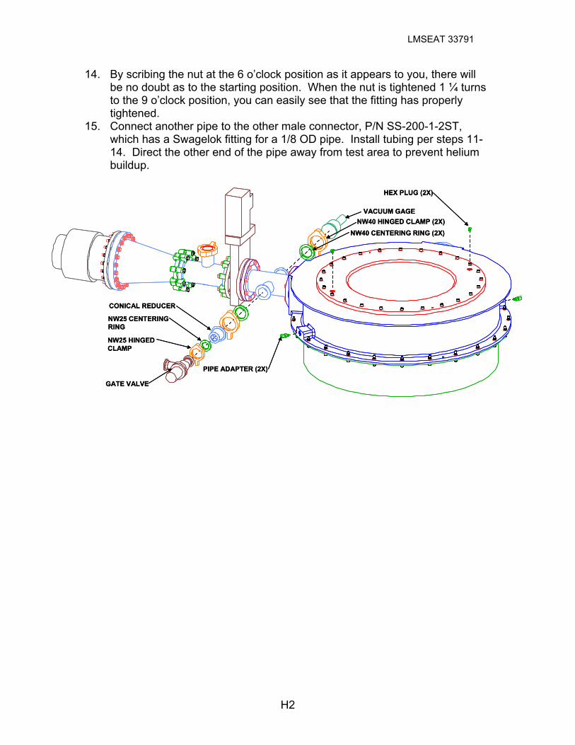
10. Connect the helium source to the male connector, P/N SS-200-1-2ST which has a Swagelok fitting for a 1/8 OD pipe.
11. Insert the tubing into the Swagelok tube fitting. Make sure that the tubing rests firmly on the shoulder of the fitting and that the nut is finger-tight.
12. Before tightening the Swagelok nut, scribe the nut at the 6 o’clock position. 13. Hold the fitting body steady with a backup wrench and tighten the nut 1 ¼
turns. Watch the scribe mark, make one complete revolution and continue to the 9 o’clock position.
G1

LMSEAT 33791
14. By scribing the nut at the 6 o’clock position as it appears to you, there will be no doubt as to the starting position. When the nut is tightened 1 ¼ turns to the 9 o’clock position, you can easily see that the fitting has properly tightened.
15. Connect another pipe to the other male connector, P/N SS-200-1-2ST, which has a Swagelok fitting for a 1/8 OD pipe. Install tubing per steps 11-14. Direct the other end of the pipe away from test area to prevent helium buildup.
VACUUM GAGE
NW40 CENTERING RING (2X)
HEX PLUG (2X)
CONICAL REDUCER
NW25 CENTERINGRING
NW40 HINGED CLAMP (2X)
NW25 HINGEDCLAMP
GATE VALVE
PIPE ADAPTER (2X)
VACUUM GAGE
NW40 CENTERING RING (2X)
HEX PLUG (2X)
CONICAL REDUCER
NW25 CENTERINGRING
NW40 HINGED CLAMP (2X)
NW25 HINGEDCLAMP
GATE VALVE
PIPE ADAPTER (2X)
G2

LMSEAT 33791
Appendix H: OTF Outer Cylinder Internal O-Ring Leak Check Setup Procedure
1. Remove the PR35 Penningvac vacuum gauge, P/N 157 89, the flex hose,
and the leak check adaptor, P/N SEG36144347-301, from the OTF. 2. Remove NW40 blank flanges, P/N 712002, from both port of the NW80 LF
to NW40 KF reducing cross, P/N MSPB1260. Install the PR35 Penningvac vacuum gauge to an open port with a NW40 centering rings, P/N 710002, and a NW40 hinged clamps, P/N 701002. Tighten wing nut until there is metal contact between the centering ring and the mating surface.
3. Install the NW40 KF to NW25 KF conical reducer, P/N KRC2540S to the open NW40 port on the NW80 to NW40 KF reducing cross, P/N MSPB1260 with a NW40 centering rings, P/N 710002 and a NW40 hinged clamps, P/N 701002. Tighten wing nut until there is metal contact between the centering ring and the mating surface.
4. Install the NW25 gate valve, P/N 311073, to the NW40 KF to NW25 KF conical reducer, P/N KRC2540S with a NW40 centering ring, P/N 710002 and a NW40 hinged clamps, P/N 701002. Tighten wing nut until there is metal contact between the centering ring and the mating surface.
5. Connect air supply and electric cord to the NW 25 gate valve, P/N 311073. Air supplied to valve needs to be cleaned with a filter of 40 microns capability.
6. Connect the He leak detector to the NW 25 gate valve, P/N 311073, with NW25 centering ring and NW 25 hinged clamp. Tighten wing nut until there is metal contact between the centering ring and the mating surface.
7. Install hollow hex plugs, P/N 2 HP5ON SS V0894, to the test ports on the Conical Flange Simulator, SDG36144342-001. Inspect NPT port and nipple to ensure that threads are free of nicks, burrs, and dirt. Screw plug into female port to the finger tight position. Torque hollow hex plug to 30-33 in-lbs from finger tight.
8. Remove both hollow hex plugs, P/N 2 HP5ON SS V0894, from the Support Ring Simulator assembly, SEG36144343-301.
9. Install male connectors, P/N SS-200-1-2ST, to the two test ports on the Support Ring Simulator assembly, SEG36144343-301. Inspect NPT port and nipple to ensure that threads are free of nicks, burrs, and dirt. Screw connector into female port to the finger tight position. Torque connectors to 6-7 ft-lbs from finger tight position.
10. Connect the helium source to the male connector, P/N SS-200-1-2ST which has a Swagelok fitting for a 1/8 OD pipe.
11. Insert the tubing into the Swagelok tube fitting. Make sure that the tubing rests firmly on the shoulder of the fitting and that the nut is finger-tight.
12. Before tightening the Swagelok nut, scribe the nut at the 6 o’clock position. 13. Hold the fitting body steady with a backup wrench and tighten the nut 1 ¼
turns. Watch the scribe mark, make one complete revolution and continue to the 9 o’clock position.
H1
LMSEAT 33791
14. By scribing the nut at the 6 o’clock position as it appears to you, there will be no doubt as to the starting position. When the nut is tightened 1 ¼ turns to the 9 o’clock position, you can easily see that the fitting has properly tightened.
15. Connect another pipe to the other male connector, P/N SS-200-1-2ST, which has a Swagelok fitting for a 1/8 OD pipe. Install tubing per steps 11-14. Direct the other end of the pipe away from test area to prevent helium buildup.
VACUUM GAGE
NW40 CENTERING RING (2X)
HEX PLUG (2X)
CONICAL REDUCER
NW25 CENTERINGRING
NW40 HINGED CLAMP (2X)
NW25 HINGEDCLAMP
GATE VALVE
PIPE ADAPTER (2X)
VACUUM GAGE
NW40 CENTERING RING (2X)
HEX PLUG (2X)
CONICAL REDUCER
NW25 CENTERINGRING
NW40 HINGED CLAMP (2X)
NW25 HINGEDCLAMP
GATE VALVE
PIPE ADAPTER (2X)
H2

LMSEAT 33791
Appendix I: OTF System Leak Check Setup Procedure 1. Install hollow hex plugs, P/N 2 HP5ON SS V0894, into all of the test ports
on the OTF, SEG36144341-301. Inspect NPT port and nipple to ensure that threads are free of nicks, burrs, and dirt. Screw plug into female port to the finger tight position. Torque hollow hex plug to 30-33 in-lbs from finger tight.
2. Bag the entire article with plastic bags. 3. Attach the helium source to the plastic bags 4. Seal leakage areas of the plastic bag with duct tape to minimize helium
leaks.
I1

LMSEAT 33791
Appendix J: Vacuum Pull Procedure 1. The test area must be cleared of unnecessary personnel. 2. Zero strain and deflection gages. 3. Begin recording strain and deflection data. 4. Turn on the pneumatic pump to open the gate valve. 5. Turn on the CM32 Combivac vacuum gauge. 6. Turn on the roughing pump and the turbopump to pull the volume to 1X10⁻⁶
torr. 7. When the volume reaches 1X10⁻⁶ torr (1.32X10⁻⁹ atm, 1.93X10⁻⁸ psi) turn off
the turbo pump and the roughing pump. Open the vent valve on the turbopump. Repressurize the volume unless otherwise specified by the test engineer.
J1
LMSEAT 33791
Appendix K: External Leak Check Procedure 1. The test area must be cleared of unnecessary personnel. 2. Turn on the CM32 Combivac vacuum gauge. 3. Turn on the He Leak detector to pull the leak check groove to 1X10⁻⁶ torr. 4. Turn on the helium leak detector function when the vacuum pressure
reaches 1X10⁻⁶ torr. 5. Fill plastic bags with 100% helium gas and continue flow of helium into the
bag to maintain a slight positive pressure above ambient. 6. Monitor the leak rate for three minutes or until the rate has stabilized to
within a 10 percent change over any ten-minute period, whichever is larger. The helium permeation rate should not rise above 5X10⁻⁷ std. cc He/s. The time involved can be changed as required by the Test Lead or the Test Engineer.
7. Record and print data 8. Turn off the helium leak detector, turbo pump, and the roughing pump at the
conclusion of the test and repressurize the OTF leak check groove volume at the conclusion of the test.
9. Flush helium from leak check groove by flooding the grooves with dry nitrogen or air. Disconnect piping for helium Supply.
K1

LMSEAT 33791
Appendix L: Internal Leak Check Procedure 1. The test area must be cleared of unnecessary personnel. 2. Turn on the pneumatic pump to open the gate valve. 3. Turn on the CM32 Combivac vacuum gauge. 4. Turn on the roughing pump and the turbopump to pull the OTF volume to
1X10⁻⁶ torr. 5. Isolate the OTF volume from the turbopump when the pressure reaches
1X10⁻⁶ torr. Turn off the turbopump and roughing pump and repressurize the pump volume.
6. Turn on the helium leak detector after isolating the OTF volume. 7. Flow 100% helium gas into leak check groove. 8. Monitor the leak rate for three minutes or until the rate has stabilized to
within a 10 percent change over any ten-minute period, whichever is larger. The helium permeation rate should not rise above 5X10⁻⁷ std. cc He/s. The time involved can be changed as required by the Test Lead or the Test Engineer.
9. Record and print data 10. Turn off helium leak detector at the conclusion of the test and repressurize
the OTF volume at the conclusion of the test. 11. Flush helium from leak check groove by flooding the grooves with dry
nitrogen or air. Disconnect piping for helium supply.
L1

LMSEAT 33791
Appendix M: System Leak Check Procedure 1. The test area must be cleared of unnecessary personnel. 2. Turn on the pneumatic pump to open the gate valve. 3. Turn on the CM32 Combivac vacuum gauge. 4. Turn on the roughing pump and the turbopump to pull the OTF volume to
1X10⁻⁶ torr. 5. Isolate the OTF volume from the turbopump when the pressure reaches
1X10⁻⁶ torr by turning off the pneumatic pump for the gate valve. 6. Turn off the turbo pump and the roughing pump. Open the vent valve on
the turbopump. 7. Turn on the helium leak detector after isolating the OTF volume. 8. Fill plastic bags with 100% helium gas and continue flow of helium into the
bag to maintain a slight positive pressure above ambient. 9. Monitor the leak rate for three minutes or until the rate has stabilized to
within a 10 percent change over any ten-minute period, whichever is larger. The helium permeation rate should not rise above 5X10⁻⁷ std. cc He/s. The time involved can be changed as required by the Test Lead or the Test Engineer.
10. Re-pressurize the volume by opening the vent valve on the helium leak detector at the conclusion of the test.
11. Flush helium from leak check groove by flooding the grooves with dry nitrogen or air.
M1

LMSEAT 33791
Appendix N: Long Term Leak Rate Procedure 1. The test area must be cleared of unnecessary personnel. 2. Turn on the pneumatic pump to open the gate valve. 3. Turn on the CM32 Combivac vacuum gauge. 4. Turn on the roughing pump and the turbopump to pull the OTF volume to 1
x 10-6 torr. 5. When the volume reaches 1X10⁻⁶ torr (1.32e-9 atm, 1.93e-8 psi) turn off the
air supply to the isolation the OTF volume. 6. Turn off the turbo pump and the roughing pump. Open the vent valve on
the turbopump. 7. Disconnect the turbopump and the roughing pump from the OTF, P/N
SEG36144341-301. 8. Personnel from the AMS-02 project will check the pressure readout at
predetermined intervals and record the vacuum values. Continue to record the vacuum level for a minimum of six months. The AMS project will determine at that time whether or not to continue the test.
9. At the conclusion of the test, reconnect the turbopump and the roughing pump and turn on the turbopump and the roughing pump to equalize the pressures on both side of the gate valve. Turn on the air supply to open the gate valve when the pressures are equal on both sides.
10. Re-pressurize the entire test article by opening the vent valve on the turbopump at the conclusion of the test.
N1

LMSEAT 33791
Appendix O: Procedure for Swagelok Tube Fittings
1. Insert the tubing into the Swagelok tube fitting. Make sure that the tubing rests firmly on the shoulder of the fitting and that the nut is finger-tight.
2. Before tightening the Swagelok nut, scribe the nut at the 6 o’clock position.
3. Hold the fitting body steady with a backup wrench and tighten the nut 1 ¼ turns. Watch the scribe mark, make one complete revolution and continue to the 9 o’clock position.
4. By scribing the nut at the 6 o’clock position as it appears to you, there will be no doubt as to the starting position. When the nut is tightened 1 ¼ turns to the 9 o’clock position, you can easily see that the fitting has properly tightened.
O1

LMSEAT 33791
Appendix P: Vacuum Gauge Measurement Uncertainty Range Uncertainty 10-8 to 10-4 mbar/Torr ± 30% of the measured value 10-3 to 10-2 mbar/Torr ± 20% of the measured value 10-2 to 102 mbar/Torr ≤ 15% of the measure value
P1