overview of cryogenic cooling in machining of · pdf fileoverview of cryogenic cooling in...
TRANSCRIPT

1
Review Paper
Yasa, E., Pilatin, S., Çolak, O.
OVERVIEW OF CRYOGENIC COOLING IN MACHINING OF TI ALLOYS AND A CASE STUDY
Received: 01 June 2012 / Accepted: 07 July 2012
Abstract: Metal cutting, e.g. turning, milling, etc., is a form of subtractive manufacturing whereby a sharp tool is used to physically remove material to achieve a desired geometry. While machining,heat is generated which limits the cutting tool life and influences the part quality and cutting forces. Many researchers have studied the mechanism behind the generated heat during metal cutting in order to optimize the machining process with a good part quality and a long tool life. This paper gives an overview of cryogenic cooling as a remedy in the field of machining Ti alloys followed by a case study: turning of Ti-6Al-4V with cryogenic cooling in TUSAS Engine Industries, Inc. Although slightly improved results were obtained, it is decided to abandon the cooling strategy due to other limitations. Key words: cryogenic cooling, machining, Ti alloys Pregled slučaja kriogenog hlađenja pri obradi Ti legura. Rezanje metala, na primer struganjem, glodanjem itd., su oblici postupaka obrade kojima se oblikovanje radnih predmeta ostvaruje skidanjem materijala oštrim alatom. Pri obradi, generiše se temperatura koja utiče kako na postojanost alata tako i na obradak i snagu rezanja. Mnogi naučnici su istraživali toplotne pojave tokom obrade rezanjem u cilju optimizacije procesa s’obzirom na kvalitet obradka i postojanost alata. Ovaj rad daje pregled kriogenog hlađenja kao preporuka pri obradi Ti legura u ovom slučaju kao: struganje Ti-6Al-4V sa kriogenim hlađenjem u TUSAS industriji motora. Iako su znatno poboljšani dobijeni rezultati, ova strategija hlađenja nije dobra zbog drugih ograničenja. Ključne reči: kriogeno hlađenje, obrada, TI legure 1. INTRODUCTION
Titanium alloys have always received interest due to their wide range of applications in aerospace, automotive, chemical and medical industries [1]. This is mainly due to their high strength-to-weight ratio and maintaining their high strength at elevated temperatures as well as their exceptional corrosion resistance. For instance, in aero-engines, titanium alloys are used both in low and high pressure compressors; and for components subjected to high centrifugal loads such as disks and blades; and for components which operate under severe fatigue conditions. On the other hand, titanium alloys are considered as difficult-to-machine materials due to high cutting temperatures and rapid tool wear. Poor machinability of titanium and its alloys are due to their inherent material properties such as low thermal conductivity increasing the tool temperature at tool/workpiece interface which affects the tool life adversely; high hot hardness and strength with low modulus of elasticity causing deformation / wear of the cutting tool during machining; high dynamic shear strength during cutting resulting in localization of shear stress and the production of abrasive saw-tooth edges; and chemical reactivity with most tool materials at elevated temperatures resulting in accelerated tool wear [2]. Advances in tooling like coated cemented carbides, ceramic tools, cubic boron nitride and solid lubricant coating as well as cooling and lubrication techniques (i.e. cryogenic systems, high pressure cooling and minimal quantity lubrication techniques) have led to
cutting Ti alloys with high thermal and chemical stability with increased machinability.
This paper mainly aims to give a review of cryogenic cooling strategies aiming at improved machinability of Ti alloys. Following the review, a case study of cryogenic cooling employed during turning of Ti-6Al-4V at TUSAŞ Engine Industries, Inc. (TEI) is presented.
2. CRYOGENIC COOLING OF TI ALLOYS
Cryogenic cooling, which is an environmentally safe
alternative to conventional emulsion cooling, is an efficient way of maintaining the temperature at the cutting interface well below the softening temperature of the cutting tool material. Liquid nitrogen is commonly used in cryogenic cooling applications because of its low cost and being environmentally friendly among other cryogenic fluids like helium, hydrogen, neon, air and oxygen [3]. Some potential benefits of cryogenic cooling mentiond in the literature are
sustainable manufacturing (cleaner, safer and environmentally friendly),
increased material removal rate, increased tool life and improved machined part surface
quality/integrity [4]. The main disadvantage of this technology, besides
additional equipment needed, is relatively high price of liquid nitrogen that is not reusable unlike conventional

2
cutting fluids circulated in the machine tools usually for weeks. Therefore, it is very crucial to select the appropriate cryogenic cooling strategy to minimize the use and maximize the efficiency.
Many aspects of machining may be affected when cryogenic cooling is integrated like workpiece material properties, cutting temperature, cutting forces, tool wear and tool life, workpiece surface roughness and dimensions as well as tool/workpiece friction and cutting forces according to Yildiz and Nalbant [5]. To be able understand the effect of cryogenic machining, many researchers have studied different aspects using different cryogenic cooling approaches. These may include pre-cooling the workpiece, indirect cryogenic cooling, cryogenic spraying with jet and direct cryogenic cooling. Hong and Ding has studied the effect of different approaches in cryogenic cooling during turning of Ti-6Al-4V [6]. As shown in Fig. 1, different cooling approaches lead to different cutting tool temperatures (measured and predicted). Cooling approaches in the order of effectiveness (worst to best) are dry cutting, cryogenic tool back cooling, emulsion cooling, pre-cooling the workpiece, cryogenic flank cooling, cryogenic rake cooling and simultaneous rake and flank cooling. The cooling efficiency trends are same even at different cutting speeds as depicted in Fig. 2.
Fig. 1. Measured and predicted tool temperature for different cooling approaches [6]
Fig. 2. Tool temperatures versus cutting speed predicted by FEM study [6]
In another study, Hong et al. also modified tools in order to increase the cryogenic cooling efficiency to gain the maximum benefit [7]. Instead of flooding the general cutting area, a liquid nitrogen delivery nozzle system is used spraying the nitrogen only to a localized zone of the tool rake and/or tool flank in well-controlled jets (see Fig. 3). As observed in Fig. 4, all cryogenic machining approaches resulted in higher main cutting force compared to dry cutting. The more nitrogen is used, the lower the cutting temperature. Hong et al. also concludes that cryogenic cooling tends to increase the cutting force because the work material becomes harder and stronger at lower temperature while the lower temperature makes the material less sticky, reducing the frictional force inherent in the cutting process [7]. The findings are consistent with the temperatures measured and calculated as shown in Table 1.
Fig. 3. Two nozzle liquid nitrogen delivery system [7]
Table 1: Temperatures encountered in dry and cryogenic machining [7]
Cutting Forces vs Cryogenic Cooling Approach
1268 1290 1308 1361
560 547 507 516476 494 520 543
0
500
1000
1500
2000
Dry cutting Flank cooling Rake cooling Both rake andflank cooling
Cooling approach
Fo
rce
(N
)
Main Cutting Force Fc Feed Force Ff Thrust Force Ft
Fig. 4. Cutting forces obtained for different cryogenic cooling approaches and dry cutting for 1.5 m/s speed, 0.254 mm feed and 1.27 mm depth of cut for Ti-6Al-4V [7]
Dhananchezian and Kumar has also used a modified
c
3
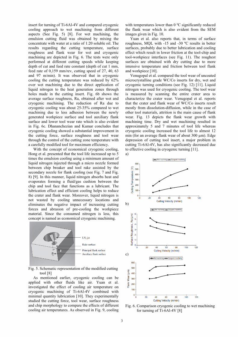
insert for turning of Ti-6Al-4V and compared cryogenic cooling approach to wet machining from different aspects (See Fig. 5) [8]. For wet machining, the emulsion cutting fluid was obtained by mixing the concentrate with water at a ratio of 1:20 soluble oil. The results regarding the cutting temperature, surface roughness and flank wear for wet and cryogenic machining are depicted in Fig. 6. The tests were only performed at different cutting speeds while keeping depth of cut and feed rate constant (depth of cut 1 mm, feed rate of 0,159 mm/rev, cutting speed of 27, 40, 63 and 97 m/min). It was observed that in cryogenic cooling the cutting temperature was reduced by 62% over wet machining due to the direct application of liquid nitrogen to the heat generation zones through holes made in the cutting insert. Fig. 6b shows the average surface roughness, Ra, obtained after wet and cryogenic machining. The reduction of Ra due to cryogenic cooling was about 25-35% compared to wet machining due to less adhesion between the newly generated workpiece surface and tool auxiliary flank surface and lower tool wear rate which is also evident in Fig. 6c. Dhananchezian and Kumar concludes that cryogenic cooling showed a substantial improvement in the cutting force, surface roughness and tool wear through the control of the cutting zone temperature with a carefully modified tool for maximum efficiency.
With the concept of economical cryogenic cooling, Hong et al. presented that the tool life increased up to 5 times the emulsion cooling using a minimum amount of liquid nitrogen injected through a micro nozzle formed between chip breaker and tool rake assisted by the secondary nozzle for flank cooling (see Fig. 7 and Fig. 8) [9]. In this manner, liquid nitrogen absorbs heat and evaporates forming a fluid/gas cushion between the chip and tool face that functions as a lubricant. The lubrication effect and efficient cooling helps to reduce the crater and flank wear. Moreover, liquid nitrogen is not wasted by cooling unnecessary locations and eliminates the negative impact of increasing cutting forces and abrasion of pre-cooling the workpiece material. Since the consumed nitrogen is less, this concept is named as economical cryogenic machining.
Fig. 5. Schematic representation of the modified cutting tool [8]
As mentioned earlier, cryogenic cooling can be applied with other fluids like air. Yuan et al. investigated the effect of cooling air temperature on cryogenic machining of Ti-6Al-4V combined with minimal quantity lubrication [10]. They experimentally studied the cutting force, tool wear, surface roughness and chip morphology to compare the effects of different cooling air temperatures. As observed in Fig. 9, cooling
with temperatures lower than 0 ºC significantly reduced the flank wear which is also evident from the SEM images given in Fig. 10.
Yuan et al. also reports that, in terms of surface roughness, MQL with -15 and -30 ºC results in better surfaces, probably due to better lubrication and cooling effect which result in lower friction at the tool-chip and tool-workpiece interfaces (see Fig. 11). The roughest surfaces are obtained with dry cutting due to more intensive temperature and friction between tool flank and workpiece [10].
Venugopal et al. compared the tool wear of uncoated microcrystalline grade WC/Co inserts for dry, wet and cryogenic turning conditions (see Fig. 12) [11]. Liquid nitrogen was used for cryogenic cooling. The tool wear is measured by scanning the entire crater area to characterize the crater wear. Venugopal et al. reports that the crater and flank wear of WC/Co inserts result mostly from dissolution-diffusion, while in the case of other tool materials, attrition is the main cause of flank wear. Fig. 13 depicts the flank wear growth with machining time. Dry and wet machining resulted in approximately 5 and 7 minutes of tool life whereas cryogenic cooling increased the tool life to almost 12 min (for an average flank wear of about 300 µm). Edge depression of cutting tool insert, a major problem in cutting Ti-6Al-4V, has also significantly decreased due to effective cooling in cryogenic turning [11]. a)
b)
c)
Fig. 6. Comparison cryogenic cooling to wet machining for turning of Ti-6Al-4V [8]

4
Fig. 7. A schematic of the economical cryogenic machining approach [9]
Fig. 8. Expanded tool life testing results in terms of total volume removal at different cutting speeds [9]
Fig. 9. Flank wear with cutting time under dry, wet and cryogenic machining at 0, -15,-30 and -45ºC [10]
Fig. 10. SEM views of the insert after machining 8 min under a) dry b) wet c) MQL d)MQL with cooling air at 0ºC e) MQL with cooling air at - 15ºC f) MQL with cooling air at -30ºC g) MQL with cooling air at -45ºC [10]
Fig. 11. Effect of cutting environments on roughness
[10]
Fig. 12. Tool wear after 5 min machining at a) 70 m/min b) 85 m/min and c) 100 m/min and feed 0.20 mm/rev for all cases [11]

5
Fig. 13. Growth of average flank wear with machining time at 85 m/min and 0.2 mm/rev
To understand the effect of cryogenic cooling on friction, Hong performed idealized disk-flat contact tests for different applications of liquid nitrogen as illustrated in Fig. 14 [12]. It was originally assumed that the liquid nitrogen lubrication mechanism was due to a reduction in friction due to a change in material properties on cooling. However, the tests revealed that that is not always the case and the effect is significantly dependent on material pairs. The second assumption before the tests were conducted was that the liquid nitrogen injection into contact zone created a lubricating film and the tests confirmed that liquid nitrogen jet was very effective in reducing friction. Other important results of the tests were that coating layer as a solid lubricant gives good results when dry machining but it may cause adverse lubrication effects at low temperatures and that liquid nitrogen cooling gives effective lubrication with uncoated inserts [12]. Fig. 15 summarizes the results obtained with Ti-6Al-4V against coated insert at 0.3 m/s.
a b
c d
e Fig. 14. Five cases of liquid nitrogen application between two materials a) bath cooling, b) disk cooling, c) jet cooling, d) jet and bath cooling and e) disk and bath cooling [12]
Fig. 15. Coefficient of friction for Ti-6Al-4V against coated insert under various cryogenic approaches at 0.3 m/s [12]
An alternative to cryogenic machining to efficiently remove heat from the cutting zone is high pressure cooling. Nandy and Paul have compared cryogenic cooling, dry and flood cooling cutting to high pressure cooling with neat oil for turning Ti-6Al-4V with micro-crystalline uncoated straight carbide inserts [13]. For the same combinations of work material, cutting tool and process parameters, their presented high pressure cooling technique provided tool lives almost 5 times that of dry, 3.5 times that of conventional flood and even two times that of cryogenic cooling which was applied at rake and flank surfaces by liquid nitrogen jets.
a)
b)

6
c)
Fig. 16. Effect of cooling approaches on cutting forces a) Feed force b) thrust force c) main cutting force for a short cut of Ti-6Al-4V [14]
Regarding the cutting forces, conflicting research results are present in the literature probably due to use of different materials and cutting conditions during the performed experiments. Sun et al. have found differences in cutting forces with different cooling approaches during a short cut only at cutting speeds lower than 20 m/min as shown in Fig. 16 [14]. At speeds lower than 20 m/min, cooling with cryogenic compressed air led to higher cutting forces. For longer cuts, significant differences were observed as seen in Fig. 17. After cutting a length of 31 m, average feed (Fx), average thrust (Fy) and average main cutting force (Fz) increase, respectively, 54%, 41% and 23% for dry cutting; 30%, 16% and 6% with compressed air cooling; and 17%, 7% and 4% for cryogenic compressed air cooling. Increases in cutting forces with time are attributed to the evolution of tool wear and the development of a built-up edge [14, 15].
Fig. 17. Effect of cooling conditions on cutting forces for a long cut of Ti-6Al-4V [14]
Fig. 18. Effect of cryogenic cooling on the cutting forces for different cutting conditions [16]
Contrary to reports presented above, in a recent study by Bermingham et al., the cutting forces are lowered by applying cryogenic cooling [16]. However, application of cryogenic cooling significantly increased the thrust force as illustrated in Fig. 18. The decrease in the main cutting force is explained by the lubricating effect of liquid nitrogen on the flank face. To test the correctness of this explanation, the flank coolant nozzle is removed and the forces are compared as given in Fig. 19. With only rake cooling, the main cutting force increases compared to dry cutting whereas cooling at both rake and flank surfaces reduces the main force for all tested conditions.
From the results presented above, it can be concluded that competing factors determine the friction and cutting forces during machining with cryogenic cooling. On one side, if liquid nitrogen is applied properly, the lubricating affect can reduce friction. On the other side, the friction between the tool and the workpiece is decreased by higher cutting speed or thermal softening whereas cryogenic cooling strengthens the workpiece and reduces the thermal softening increasing the friction [16]. Their overall conclusion was that choosing the correct combination of feed rate and depth of cut is far more effective in extending tool life rather than the selection of inefficient cutting parameters with a cryogenic cooling strategy.
Fig. 19. Effect of cryogenic cooling approaches on the main cutting force for different cutting conditions [16]
As summarized in this paper, many researchers have investigated the effect of cryogenic cooling while

7
machining Ti-6Al-4V, mainly for turning. Additional equipment and high cost of liquid nitrogen are the main disadvantages of cryogenic cooling, while, compared to conventional cooling, better results are obtained with modified tool inserts to optimize the frictional and thermal properties, regarding the tool wear. This brings an additional limitation for the implementation of the technology in real industrial environment.
3. A CASE STUDY
In TUSAS Engine Industries, Inc. (TEI), cryogenic cooling strategy was tested for the application of turning of Ti-6Al-4V workpieces. The cooling was applied as flood cooling; no special or modified tooling was involved. The utilized cryogenic set-up, consisting of a liquid nitrogen tank, a control system for cryogenic cooling, a vacuum tube and a phase separator, is illustrated in Fig. 20. The liquid nitrogen from the tank travels along the vacuum tube connected to the phase separator and finally onto the insert as illustrated in Fig. 21. A Kistler multi-component force dynamometer was used during tests to capture generated cutting forces. The tool holder with the cutting insert is mounted on top of the dynamometer to be able to measure cutting forces during cryogenic (with liquid nitrogen), dry and wet cutting conditions. Increases in cutting forces are used to predict the tool wear and tool life. The workpiece geometry on which the cutting tests were performed is depicted in Fig. 22.
Fig. 20. Cryogenic cooling set-up on a VTN10 CNC vertical lathe in TEI [17]
Fig. 21. Application of cryogenic cooling on an insert while the cutting forces are measured by a Kistler dynamometer [17]
Fig. 22. Turning of Ti-6Al-4V with a coated carbide insert with cryogenic cooling [17]
The cutting tests were performed with different combinations of depth of cut and cutting speed as shown in Table 2. Two cutting speeds (90 and 135 m/min) and three depths of cut (0.50, 1 and 1.27 mm) in the range of generally used cutting conditions were tested. Test 1 Test 2 Test 3 Test 4
Cutting speed (m/min) 90 90 90 135
Feed rate (mm/rev) 0,15 0,15 0,15 0,15
Depth of cut (mm) 0,50 1,00 1,27 0,50 Table 2: Tested cutting parameters
The cutting forces obtained with different cooling strategies are shown in Fig. 23 (See Fig. 24 for cutting force directions). Fig. 23a depicts the case for dry machining where a significant amount of wear was observed after 225 seconds. Cryogenic cooling increases the tool life to 400 seconds while wet cutting with Castrol Alusol A (4-6% concentration) cutting fluid exhibits a very close tool life of about 350 seconds. For all test cases, the trend is similar: dry cutting gives the highest rate of tool wear whereas cryogenic machining and wet cutting gives similar results as shown in Table 3. a)
b)

8
c)
Fig. 23. Cutting forces generated during a) dry cutting, b) cryogenic machining and c) wet cutting with Castrol Alusol cutting fluid
Fig. 24. Direction of cutting forces with respect to the cutting tool
As observed from these and other tests performed at TEI, cryogenic cooling did not improve the tool life significantly but gave similar results compared to wet cutting with conventional cutting fluids. Although cryogenic cooling is a clean and sustainable cooling technique compared to use of cutting fluids, other than the cost of liquid nitrogen and additional equipment needed, some limitations were experienced with cryogenic cooling in industrial environment which is different than a lab environment in many ways.
First of all, due to the bulky system used in these tests, it was not possible to cut internal diameters with cryogenic cooling due to the accessibility problems rising from workpiece geometry and set-up. Therefore, a smaller system needs to be developed to be able to cut all types of geometries. Tool life in [s] Test 1 Test 2 Test 3 Test 4
Dry Cutting 800 225 90 70 Castrol A wet cutting 1200 350 100 500 Cryogenic machining 400 120 440
Table 3: Tool life in seconds before excessive wear is observed
Secondly, due to the increase of the nitrogen in the gas phase in the tank, a safety valve opens up and releases the cold nitrogen inside the factory environment (See Fig. 25a). The nitrogen gas is non-toxic but if brought into contact with skin, it may lead to severe frostbites. This is an important safety issue to be tackled with in factory environment. Moreover, the release of nitrogen gas via safety valve or during cutting via phase separator leads to significant increase in the
amount of nitrogen used and therefore, in the cost of cryogenic cooling strategy as mentioned earlier (See Fig. 25b). a)
b)
Fig. 25. Gas leakage of nitrogen a) via safety valve of the tank b) during cutting via phase separator
Another issue with flood cryogenic cooling is the excessive cooling of the workpiece as depicted in Fig. 26. This may be acceptable in some sectors, yet in aerospace applications, where the part dimensions are quite often measured even in between different cutting tasks to satisfy very tight tolerances, small changes in the workpiece dimensions are not acceptable. Excessive cooling may cause the part to be out of tolerances or wrong measurements may be taken which may lead to part’s being scrap or rework. This may cause significant cost increase especially while working with expensive materials like Ni-based superalloys and Ti alloys.
Fig. 26. Cooling of the workpiece during flood cryogenic cooling
Due to the limitations explained above, TEI decided not to utilize cryogenic cooling in turning of Ti or Ni-based superalloys and abandoned this cooling strategy after trial cuts.

9
4. CONCLUSIONS Cryogenic cooling, an environmentally safe
alternative to conventional emulsion cooling, is an efficient way of maintaining the temperature at the cutting interface well below the softening temperature of the cutting tool material. Theoretically, this would increase the machinability of difficult-to-cut aerospace materials like Ti and Ni-based superalloys. Additional equipment and high cost of liquid nitrogen are the main disadvantages of cryogenic cooling. However, as many researchers point out, compared to conventional cooling, with cryogenic cooling better tool lives are obtained with modified tool inserts that optimize the frictional and thermal properties. Some aspects of the technology, yet, limit its use in real industrial applications other than lab machines, such as safety issues regarding handling liquid and gas nitrogen, workpiece cooling leading to unsatisfied tolerances for in-cutting measurements and size of the cryogenic set-up to be able to access internal diameters. As mentioned earlier, it may be a preferred technology in the sectors where these limitations are invalid or less significant. 5. REFERENCES 1. P.J. Arrazola, A. Garay, L.-M. Iriarte, M.
Armendia, S. Marya, F. Le Maitre, Machinability of titanium alloys (Ti6Al4V and Ti555.3”, Journal of Materials Processing Technology, 209, pp.2223-2230, 2009.
2. E.O. Ezugwu, J.Bonney, Y.Yamane, An overview of the machinability of aeroengine alloys, Journal of Materials Processing Technology, 134, pp. 233-253, 2003.
3. A. Ahmad-Yazid, Z. Taha, I.P. Almanar, A review of cryogenic cooling in high speed machining (HSM) of mold and die steels, Scientific Research and Essays, 5/5, pp. 412-427, 2010.
4. J. Kopac, Achievements of sustainable manufacturing by machining, Journal of Achievements in Materials and Manufacturing Engineering, 34/2, pp.180-187, 2009.
5. Y. Yildiz, M. Nalbant, A review of cryogenic cooling in machining processes, International Journal of Machine Tools and Manufacture, 48, pp.947-964, 2008.
6. S.Y. Hong, Y. Ding, Cooling approaches and cutting temperatures in cryogenic machining of Ti-6Al-4V, International Journal of Machine Tools and Manufacture, 41, pp. 1417-1437, 2001.
7. S.Y. Hong, Y. Ding, W-C. Jeong, Friction and cutting forces in cryogenic machining of Ti-6Al-4V, International Journal of Machine Tools and Manufacture, 41, pp. 2271-2285, 2001.
8. M. Dhananchezian, M.P. Kumar, Cryogenic turning of the Ti-6Al-4V alloy with modified cutting tool inserts, Cryogenics, 51, pp. 34-40, 2011.
9. S.Y. Hong, I. Markus, W-C. Jeong, New cooling approach and tool life improvement in cryogenic machining of titanium alloy Ti-6Al-4V, International Journal of Machine Tools and Manufacture, 41, pp.2245-2260, 2001.
10. S.M. Yuan, L.T. Yan, W.D. Liu, Q. Liu, Effects of cooling air temperature on cryogenic machining of Ti-6Al-4V alloy, Journal of Materials Processing Technology, 211/3, pp.353-362, 2010.
11. K.A. Venugopal, S. Paul, A.B. Chattopadhyay, Tool wear in cryogenic turning of Ti-6Al-4V alloy, Cryogenics, 47, p.12-18, 2007.
12. S.Y. Hong, Lubrication mechanisms of LN2 in ecological cryogenic machining, Machining Science and Technology, 10, pp.133-155, 2006.
13. A.K. Nandy, S. Paul, Effect of coolant pressure, nozzle diameter, impingement angle and spot distance in high pressure cooling with neat oil in turning of Ti-6Al-4V, Machining Science and Technology, 12/4, pp.445-473, 2008.
14. S.Sun, M. Brandt, M.S. Dargusch, Machining Ti-6Al-4V alloy with cryogenic compressed air cooling, International Journal of Machine Tools and Manuactıre, 50, pp. 933-942, 2010.
15. Y.Su, N. He, L. Li, X. L. Li, An experimental investigation of effects of cooling/lubrication conditions on tool wear in high-speed end milling of Ti-6Al-4V, Wear, 261, pp.760-766, 2006.
16. M.J.Bermingham, J.Kirsch, S.Sun, S.Palanisamy, M.S. Dargusch, New observations on tool life, cutting forces and chip morphology in cryogenic machining of Ti-6Al-4V, International Journal of Machine Tools and Manufacture, 51, pp. 500-511, 2011.
17. Z.Y. Wang, K.P. Rajurkar, Cryogenic machining of hard-to-cut materials, Wear, 239, pp.168-175, 2000.
6. ACKNOWLEDGEMENT The authors would like to thank TUBITAK, The Scientific and Technological Research Council of Turkey, for their contribution to this study with funding of the project “TEYDEB 9100011: Sürdürülebilir ve Yenilikçi Kreyojenik İşleme Teknolojilerinin Geliştirilmesi”.
Authors: Prof.dr.Everen Yasa, Division PMA, Dept. Mech. Eng., K.U.Leuven Celestijnenlaan 300B, 3001 Heverlee, Belgium. Prof.dr. Pilatin Semih, Prof.dr. Oguz Colak, Suleyman Demirel University, Faculty of Technology, Department of Manufacturing Engineerings. Phone:+90.246.211 1674 Fax:+90.246.211 1673 E-mail: [email protected] [email protected] [email protected]