overview of the basic seismic resistant design...
TRANSCRIPT

CEE 227 - Earthquake Engineering
U.C. Berkeley Spring 2003 ©UC Regents 3-1
Overview of the Basic SeismicResistant Design Process
vA quick look at the overalldesign process.
vThen look at some basic reasons for usingnonlinear response to help us achieveperformance objectives
CEE 227 - Earthquake Engineering
U.C. Berkeley Spring 2003 ©UC Regents 3-2
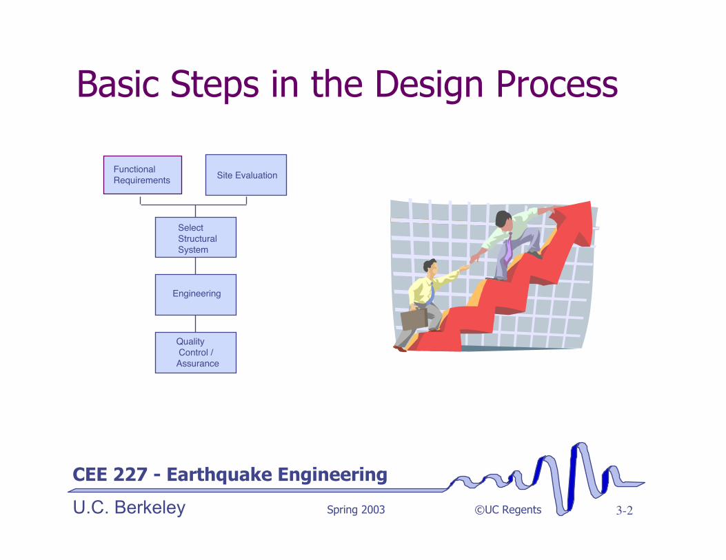
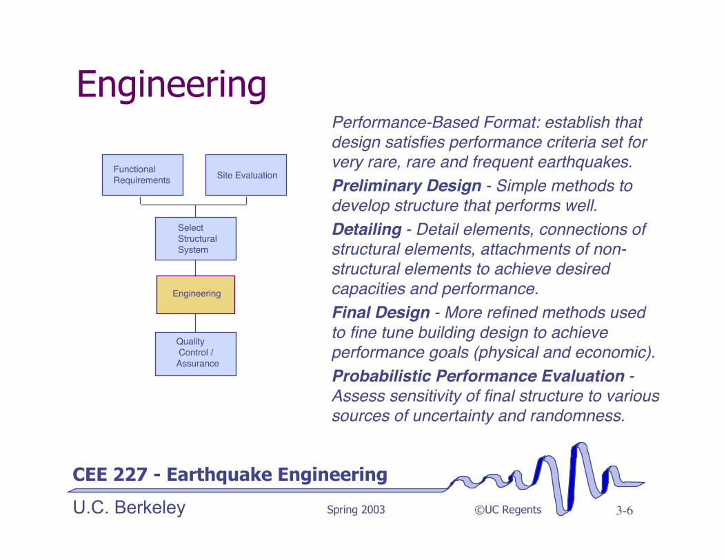
Basic Steps in the Design Process
Site Evaluation
Select Structural System
Engineering
Quality Control /Assurance
Functional Requirements

CEE 227 - Earthquake Engineering
U.C. Berkeley Spring 2003 ©UC Regents 3-3
Functional /Operational Requirementsv Loading - Dead, live, etc.v Spatial requirements (minimum area,
height limits, interior open space, etc.)v Operating restrictions (deflection,
settlement, vibration limits)v Expected life of structure
v Time available for constructionv Local cost of materials/laborv Value of moneyv Assess owner’s aversion to riskv Establish performance levels and key
response parameters for frequent, rareand very rare seismic events and windstorms.
Functional Requirements Site Evaluation
Select Structural System
Engineering
Quality Control /Assurance

CEE 227 - Earthquake Engineering
U.C. Berkeley Spring 2003 ©UC Regents 3-4
Site Evaluationv Settlement potentialv Thermal settingv Windv Mechanical vibration (trains, etc.)v Seismic¸ Fault rupture¸Differential ground movement¸ Liquefaction potential¸Slope instability¸ Tsunami and seiche¸ Fire and flood¸Ground shaking
Functional Requirements
SiteEvaluation
Select Structural System
Engineering
Quality Control /Assurance

CEE 227 - Earthquake Engineering
U.C. Berkeley Spring 2003 ©UC Regents 3-5
Selection of Structural SystemTypically, several types of structures arepicked and investigated at least throughthe preliminary or schematic design stage.Consideration to alternative:
• Materials for structural and non-structural elements
• Connection types (fixed, partiallyrestrained, etc.)
• Configuration (regular or not?)• Load carrying system (complete
vertical and horizontal load systems)• Type of foundation
Assess seismic and functionalperformance, and economic costs.
Functional Requirements Site Evaluation
SelectStructuralSystem
Engineering
Quality Control /
Assurance
CEE 227 - Earthquake Engineering
U.C. Berkeley Spring 2003 ©UC Regents 3-6
EngineeringPerformance-Based Format: establish thatdesign satisfies performance criteria set forvery rare, rare and frequent earthquakes.Preliminary Design - Simple methods todevelop structure that performs well.Detailing - Detail elements, connections ofstructural elements, attachments of non-structural elements to achieve desiredcapacities and performance.Final Design - More refined methods usedto fine tune building design to achieveperformance goals (physical and economic).Probabilistic Performance Evaluation -Assess sensitivity of final structure to varioussources of uncertainty and randomness.
Functional Requirements Site Evaluation
Select Structural System
Engineering
Quality Control /Assurance

CEE 227 - Earthquake Engineering
U.C. Berkeley Spring 2003 ©UC Regents 3-7
Generally most important design stage.Focus on simple methods to developstructure that performs well(proportions, load path completion,stiffness, strength, etc.)Iterative Process:¸ Immediate Occupancy Goal: Elastic Analysis, very
simple models and elastic spectrum¸ “Life Safe” Goal: Elastic analysis, and “equiv. elastic”
spectrum.¸ Collapse Prevention Goal: Simplified nonlinear
analysis, nonlinear design response spectrum.
vIntegrate design requirementsvEvaluate designsvRe-do, if needed
Engineering: Preliminary Design
Functional Requirements Site Evaluation
Select Structural System
Engineering
Quality Control /Assurance

CEE 227 - Earthquake Engineering
U.C. Berkeley Spring 2003 ©UC Regents 3-8
Current codes do not attempt to relatedetails quantitatively to predicteddeformation capacities. Nominal “ductile”details typically used -- relatively non-deteriorative and insensitive to loadinghistory effects.
Tend is towards identifying qualitativecatagories. such as “special,”“intermediate” and “ordinary” detailswhich possess different abilities to deforminelastically
Engineering: Detailing
Functional Requirements Site Evaluation
Select Structural System
Engineering
Quality Control /Assurance

CEE 227 - Earthquake Engineering
U.C. Berkeley Spring 2003 ©UC Regents 3-9
PBEE format: Design using computedestimates of demands.
‘ Immediate Occupancy Goal: Focus onstrength. Some damage permitted.
‘ Life Safe Goal: Focus on triggers ofexpensive/hazardous behavior (spalling,buckling, falling hazards, etc.)
‘ Collapse Prevention Goal: Focus onultimate deformation capacity ofmember, connection and system thatwould lead to partial or global collapseof structure.
‘Integrate and evaluate
Engineering: Detailing
Functional Requirements Site Evaluation
Select Structural System
Engineering
Quality Control /Assurance

CEE 227 - Earthquake Engineering
U.C. Berkeley Spring 2003 ©UC Regents 3-10
Generally most analysis-oriented step.Focus on refined methods topredict/evaluate demands on nearlycompleted structural design.Iterative Process:
‘ Immediate Occupancy Goal: Elastic Analysis,refined models and elastic spectrum, 2D vs 3D
‘ “Life Safe” Goal: Elastic analysis, and “equiv.elastic” or nonlinear spectrum.
‘ Collapse Prevention Goal: Nonlinear analysis(static push-over with nonlinear design responsespectrum, or dynamic time history analysis).
‘ Integrate design requirements‘ Evaluate designs (details, goals)‘ Re-do if needed
Engineering: Final Design
Functional Requirements Site Evaluation
Select Structural System
Engineering
Quality Control /Assurance

CEE 227 - Earthquake Engineering
U.C. Berkeley Spring 2003 ©UC Regents 3-11
Infrequently done at presentFocus on refined methods to assessreliability of structure being able toachieve performance objectivesIterative Process: (see FEMA 350-352)
‘ Immediate Occupancy Goal: Elastic Analysis,refined models and elastic spectrum, 2D vs 3D
‘ “Life Safe” Goal: Elastic analyses, and “equiv.elastic” or nonlinear spectrum (+1s).
‘ Collapse Prevention Goal: Nonlinear analysis(static push-over with nonlinear responsespectrum, dynamic time history analyses, etc.).
‘ Integrate performance information‘ Evaluate confidence in achieving objectives
Engineering: Reliability Assessment
Functional Requirements Site Evaluation
Select Structural System
Engineering
Quality Control /Assurance

CEE 227 - Earthquake Engineering
U.C. Berkeley Spring 2003 ©UC Regents 3-12
Quality Control/AssuranceEngineering QualityVision 2000 RecommendsEngineering Peer Review¸ Safety Critical and Essential/Hazardous
performance objectives.¸ Advanced or unusual technologies¸ Rehabilitation projects involving
untested details¸ Complex or important structures
Should include all stages of design:establishment of project goals andprocedures, Schematic DesignPhase, Design Development Phase,and Construction Document Phase
Functional Requirements Site Evaluation
Select Structural System
Engineering
Quality Control /
Assurance

CEE 227 - Earthquake Engineering
U.C. Berkeley Spring 2003 ©UC Regents 3-13
Quality Control/AssuranceConstruction QC/QA ProgramsCritical to achievement of performance goalsv Contractor should have in-house quality control program.v Owner should have independent quality assurance program,¸ Includes on-site and shop inspection.¸ Preconstruction conference with engineer, contractor and inspectors. Local
building departments are not set up to do this.
See: FEMA 353 for steel construction
Similarly, maintenance is a problem for many types of structure(corrosion, defeat of base isolation systems, etc.)

CEE 227 - Earthquake Engineering
U.C. Berkeley Spring 2003 ©UC Regents 3-14
Approaches to Seismic Design
Some Issues to Consider:v General types of engineering demand
parametersvWhat design characteristic controls them?vWhere can we use inelastic behavior to our
advantage?v Design methods (formats that address seismic
design issues best)

CEE 227 - Earthquake Engineering
U.C. Berkeley Spring 2003 ©UC Regents 3-15
Introduction - Design Approaches
For immediate occupancyand similar performancegoals, we generally willwant to:¸ Limit drifts (stiffness)¸ Limit accelerations (strength)¸ Limit yielding (strength and
proportioning)
Elastic design approachesgenerally suffice
For collapse prevention limitstates, we need to¸ limit drifts to prevent static and
dynamic instability (stiffness)¸ Prevent brittle failure modes
(limit forces)¸ Insure adequate deformation
capacity in ductile failure modes(detailing)¸ Limit deformation demands
(stiffness)
Inelastic approaches needed
CEE 227 - Earthquake Engineering
U.C. Berkeley Spring 2003 ©UC Regents 3-16
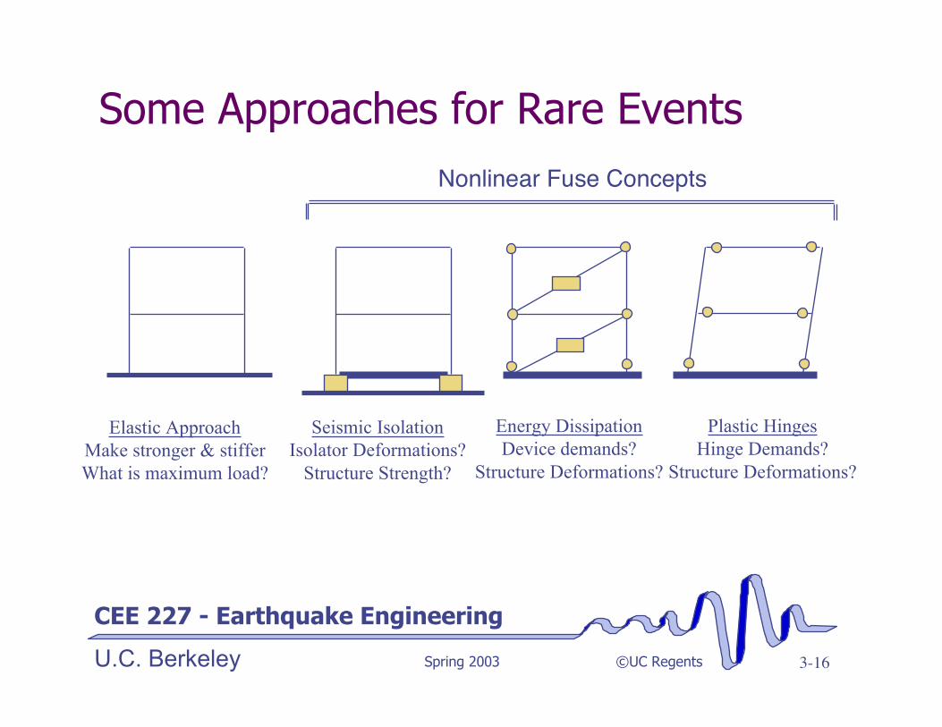
Some Approaches for Rare Events
Elastic ApproachMake stronger & stifferWhat is maximum load?
Nonlinear Fuse Concepts
Seismic IsolationIsolator Deformations?
Structure Strength?
Energy DissipationDevice demands?
Structure Deformations?
Plastic HingesHinge Demands?
Structure Deformations?

CEE 227 - Earthquake Engineering
U.C. Berkeley Spring 2003 ©UC Regents 3-17
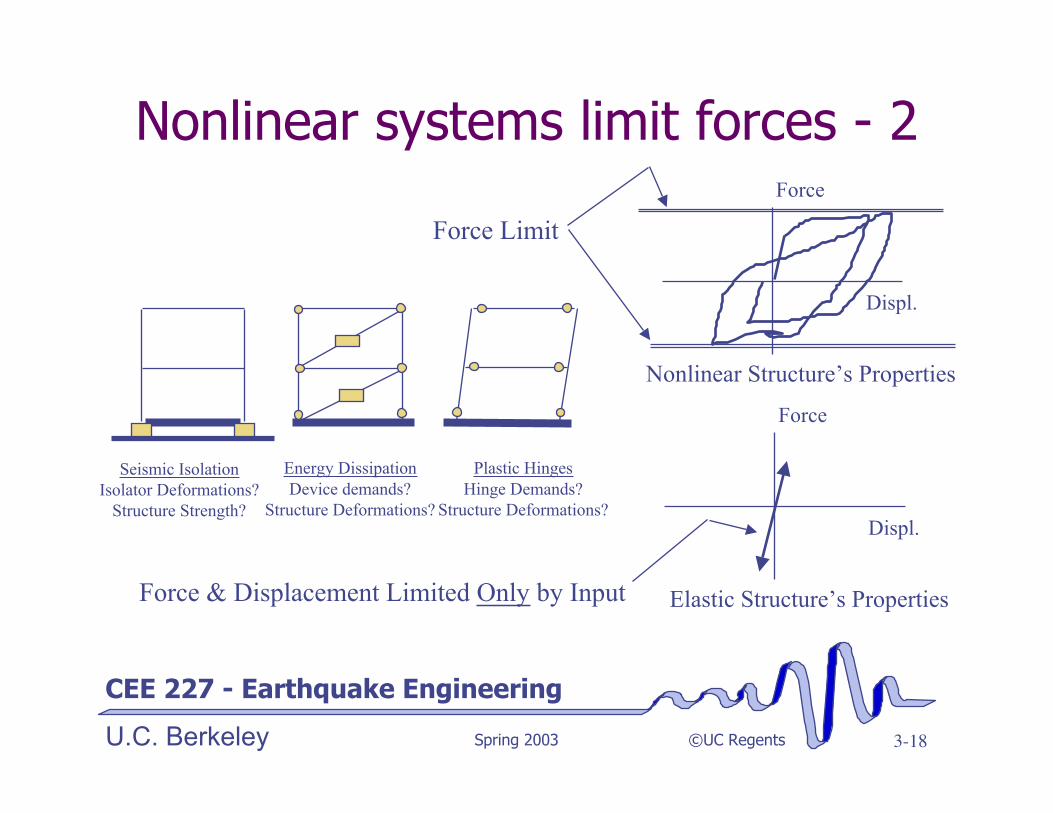
Nonlinear systems limit forces
Seismic IsolationIsolator Deformations?
Structure Strength?
Energy DissipationDevice demands?
Structure Deformations?
Plastic HingesHinge Demands?
Structure Deformations?
Device or member properties
Deform.
Load
Structure properties
Displ.
Force
CEE 227 - Earthquake Engineering
U.C. Berkeley Spring 2003 ©UC Regents 3-18
Nonlinear systems limit forces - 2
Seismic IsolationIsolator Deformations?
Structure Strength?
Energy DissipationDevice demands?
Structure Deformations?
Plastic HingesHinge Demands?
Structure Deformations?
Nonlinear Structure’s Properties
Displ.
Force
Force Limit
Elastic Structure’s Properties
Displ.
Force
Force & Displacement Limited Only by Input

CEE 227 - Earthquake Engineering
U.C. Berkeley Spring 2003 ©UC Regents 3-19
These systems allow us to controldamage distribution
Seismic IsolationIsolator Deformations?
Structure Strength?
Energy DissipationDevice demands?
Structure Deformations?
Plastic HingesHinge Demands?
Structure Deformations?
Except for the isolatedsystem, these systemsare staticallydeterminant near-collapse:¸Know forces in:
• all members• foundations
¸Make all otherlocations stronger tocontrol damagedistribution!
Pick locations where localdamage is acceptable
CEE 227 - Earthquake Engineering
U.C. Berkeley Spring 2003 ©UC Regents 3-20
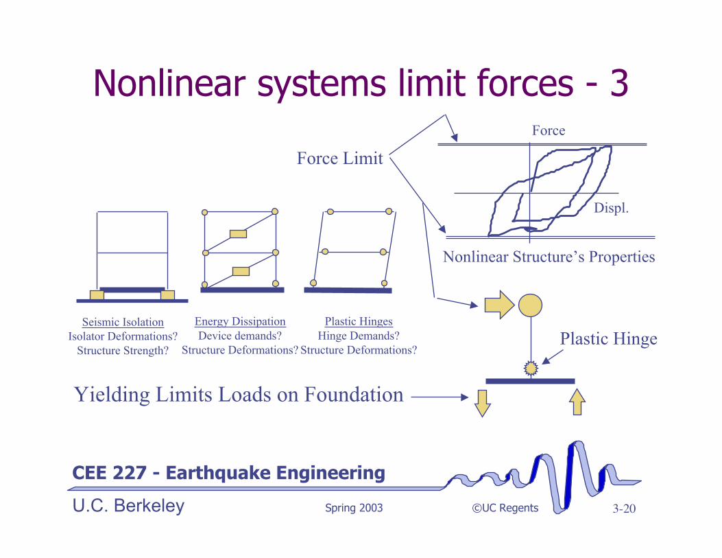
Nonlinear systems limit forces - 3
Seismic IsolationIsolator Deformations?
Structure Strength?
Energy DissipationDevice demands?
Structure Deformations?
Plastic HingesHinge Demands?
Structure Deformations?
Nonlinear Structure’s Properties
Displ.
Force
Force Limit
Plastic Hinge
Yielding Limits Loads on Foundation

CEE 227 - Earthquake Engineering
U.C. Berkeley Spring 2003 ©UC Regents 3-21
Nonlinear systems limit accelerations
Seismic IsolationIsolator Deformations?
Structure Strength?
Energy DissipationDevice demands?
Structure Deformations?
Plastic HingesHinge Demands?
Structure Deformations?
Nonlinear Structure’s Properties
Displ.
Force
Force Limit
Plastic Hinge
Mp
Fy = Mp/H
Fy
Ma + FD + FS = -Mag
FS = -M(ag+a) = -Matotal
atotal<Fy/M
CEE 227 - Earthquake Engineering
U.C. Berkeley Spring 2003 ©UC Regents 3-22
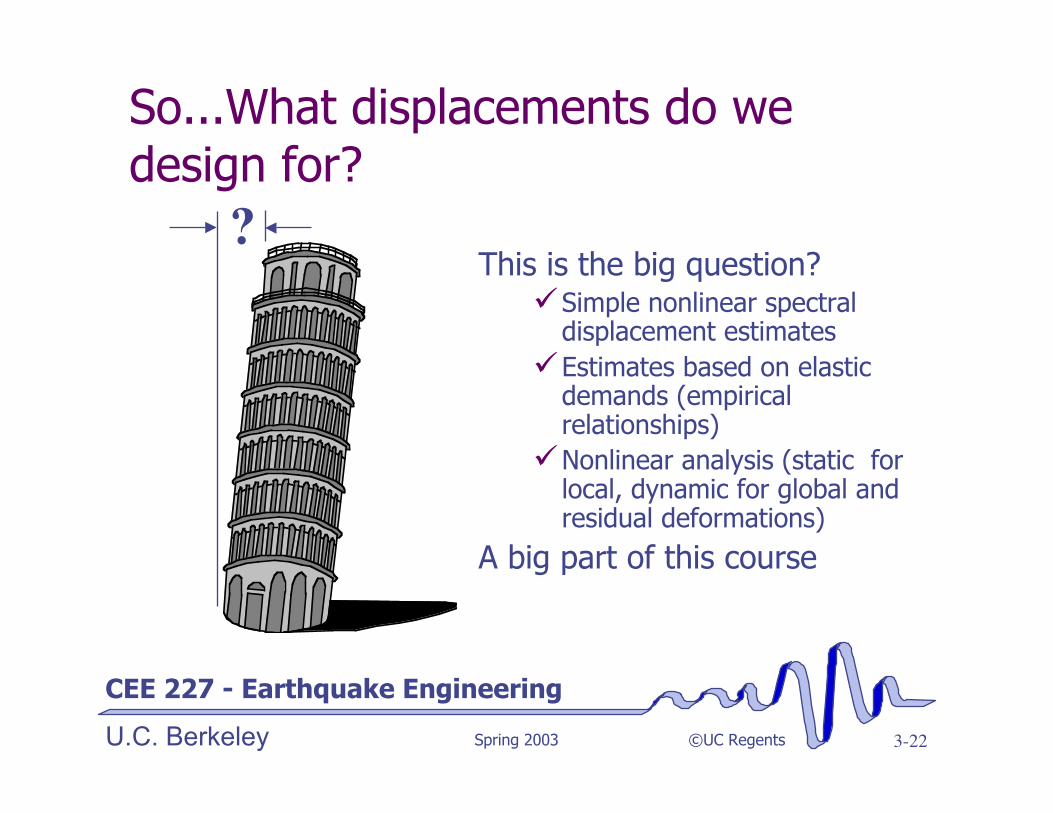
So...What displacements do wedesign for?
This is the big question?¸Simple nonlinear spectral
displacement estimates¸Estimates based on elastic
demands (empiricalrelationships)¸Nonlinear analysis (static for
local, dynamic for global andresidual deformations)
A big part of this course
?

CEE 227 - Earthquake Engineering
U.C. Berkeley Spring 2003 ©UC Regents 3-23
Common Design Methods
v Allowable Stress/Elastic Methods¸ older codes
v Capacity design methods¸New Zealand code since 1960s¸ various parts of concrete sections of UBC and hidden in some
parts of steel UBC provisions
v Damage Tolerant Design¸ Coming from blast and progressive collapse limit state
considerations. European and Japanese building practice.
v Plastic Design¸ Very useful, but often too complex for hand calculations.
v Displacement-based Design

CEE 227 - Earthquake Engineering
U.C. Berkeley Spring 2003 ©UC Regents 3-24
Allowable Stress / Elastic Methods
H=12
6
Qy=5
Piles
Design Loadsand Dimensions
Qy=5W=20
P = 20/2 + 5*12/6 = 20P=20/2 - 5*12/6 = 0
Vcol = 5
Mmax = 5*12 = 60Vp= 6Mp= 78
Cp=30Tp = 0
Design Internal ForcesProvided Capacity
C ≥ D
Vp,p=4
Vpile = 2.5

CEE 227 - Earthquake Engineering
U.C. Berkeley Spring 2003 ©UC Regents 3-25
Response of Strength Designed Structure
Element Load Q to ReachElement Capacity
ElementOvercapacity
Column shear 6 1.2ColumnMoment
78/12=6.5 1.3
PileCompression
(30-10)*6/12=10 2
Pile Tension (0+10)*6/12 = 5 1.0Pile shear 2*4 = 8 1.6 Provided Capacity
C ≥ D
Vp= 6Mp= 78
Cp=30Tp = 0
Q=?
Vp,p=4
Load structure until something fails.Assuming we are looking for firstdamage, structure is elastic

CEE 227 - Earthquake Engineering
U.C. Berkeley Spring 2003 ©UC Regents 3-26
Capacity Design Approach
Minimum Capacitiesbeyond Plastic Hinge
Vp= 8.1Mp= 78
Cp=26.3Tp = -6.3Vp,p=1.6
Target Behavior
Mp= 78
Q=?Element Force in element
when columnplastic hinge forms
ElementOvercapacity
Column shear 6.5*1.25 = 8.1 1.25ColumnMoment
78/12=6.5 1.0
PileCompression
20/2+1.25(6.5)12/6 =26.3
1.25
Pile Tension 20/2 -1.25(6.5)12/6 = -6.3
1.25
Pile shear 1.25*6.5/2= 4.1 1.25
FIXED
1.25 factor used here to provide margin of safety against otherelements reaching capacity prior to column plastic hinge
CEE 227 - Earthquake Engineering
U.C. Berkeley Spring 2003 ©UC Regents 3-27
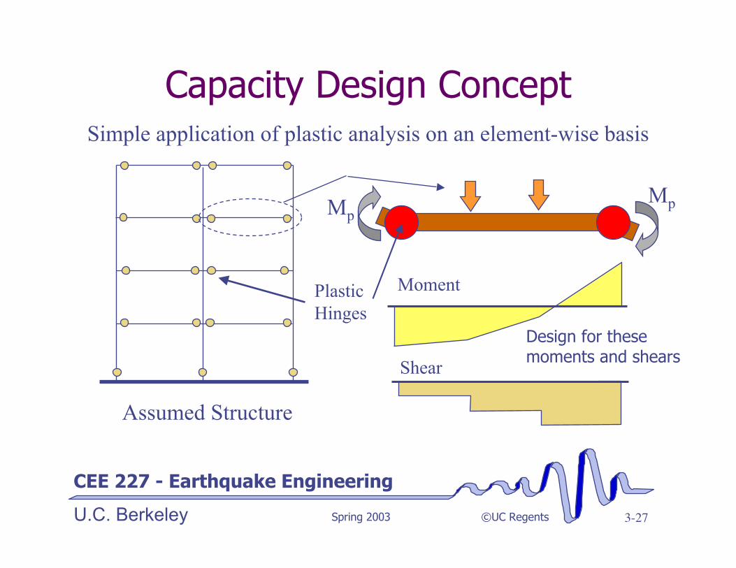
Capacity Design Concept
Assumed Structure
Simple application of plastic analysis on an element-wise basis
Plastic Hinges
MpMp
Moment
Shear
Design for thesemoments and shears
CEE 227 - Earthquake Engineering
U.C. Berkeley Spring 2003 ©UC Regents 3-28
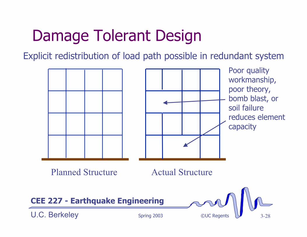
Damage Tolerant Design
Poor qualityworkmanship,poor theory,bomb blast, orsoil failurereduces elementcapacity
Planned Structure Actual Structure
Explicit redistribution of load path possible in redundant system
CEE 227 - Earthquake Engineering
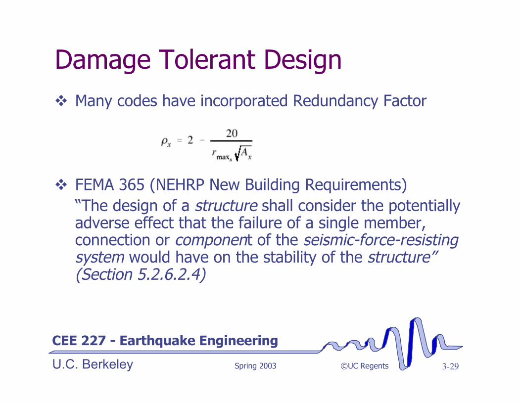
U.C. Berkeley Spring 2003 ©UC Regents 3-29
Damage Tolerant Designv Many codes have incorporated Redundancy Factor
v FEMA 365 (NEHRP New Building Requirements)“The design of a structure shall consider the potentiallyadverse effect that the failure of a single member,connection or component of the seismic-force-resistingsystem would have on the stability of the structure”(Section 5.2.6.2.4)

CEE 227 - Earthquake Engineering
U.C. Berkeley Spring 2003 ©UC Regents 3-30
Summary
Design Process¸ Many steps¸ Multiple objectives require tradeoffs¸ Iterative
Tools and methodologies¸ Trend to more quantitative approaches¸ Various formats and concepts to help us achieve a
structure likely to achieve performance objectives¸ Trend towards explicit reliability assessment