overview of the x-57 structural requirements, …...overview of the x-57 structural requirements,...
TRANSCRIPT

Overview of the X-57 Structural Requirements, Modifications, and Airworthiness
Wesley Li
Aerostructures Branch
NASA Armstrong Flight Research Center Edwards, CA
• https://ntrs.nasa.gov/search.jsp?R=20190026541 2020-03-11T02:11:43+00:00Z

Outline
• X-57 Maxwell Overview
• Structural Design
• Static Structural Analysis and Airworthiness
– Mod II
– Mod III
– Mod IV
• Aeroelasticity
2AIAA Aviation 2019
Tecnam P2006TWing loading17 lb/ft2
X-57 Wing loading45 lb/ft2
June 17-21, 2019
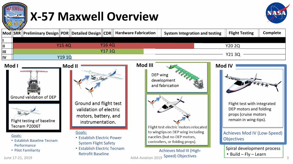
X-57 Maxwell Overview
Spiral development process• Build – Fly – Learn
Flight test with integrated DEP motors and folding props (cruise motors remain in wing-tips).
Goals:• Establish Electric Power
System Flight Safety• Establish Electric Tecnam
Retrofit Baseline
Goals:• Establish Baseline Tecnam
Performance • Pilot Familiarity Achieves Mod III (High-
Speed) Objectives
Achieves Mod IV (Low-Speed) Objectives
Mod IIMod I Mod III Mod IV
Mod SRR Preliminary Design PDR Detailed Design CDR Flight Testing Complete
I
II
III
IV
System Integration and testingHardware Fabrication
AIAA Aviation 2019
Y20 2Q
Y21 3QY17 1Q
Y19 1Q
Y15 4Q Y16 4Q
3June 17-21, 2019
.....
Ground validation of DEP
Flight testing of baseline Tecnam P2006T
Ground and fl ight test validation of electric motors, battery, and
instrumentation.
DEP wing
deve lopment and fabricat ion
Flight test electric otors relocated to wingtips on DEP wing including nacelles {but no DEP motors, contro ll ers, or fo lding props).
•

X-57 Participating Organizations
4AIAA Aviation 2019June 17-21, 2019
NASA Langley: Vehicle, W ing, Performance, Cont ro ls I PTs
NASA Armstrong: Power, Inst ru ment at ion IPTs, Flight Ops
NASA Glenn: Battery Test ing, Therma l!
Analys is, HL Motor Cont ro lller Development (M od IV)
Empirica l Sys. Aero.: Prime cont ractor
Sca led Composit,es: Mod II Integrat ion (batteries,
motors, cont ro llers, cockp it )
Joby Aviatiion: Mod II Cru iise Motor & Cont ro ller development
Xperimenta ll: W ing design and manufacturing
Electric Power Sys.: Battery deve lopment
TMC Technologi,es: Soft ware V&V
Tecnam : Baseline COTS ai rfra me
w it hout engines
Joby
Elect ric Power
Systems Xperiment al Sca led
Composites
NASA GRC
NASAAFRC
TMC Technologies of West Virginia
NASA LaRC
•
Tecnam
Italy-
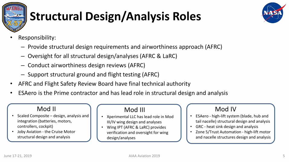
Mod II• Scaled Composite – design, analysis and
integration (batteries, motors, controllers, cockpit)
• Joby Aviation - the Cruise Motor structural design and analysis
Structural Design/Analysis Roles
• Responsibility:
– Provide structural design requirements and airworthiness approach (AFRC)
– Oversight for all structural design/analyses (AFRC & LaRC)
– Conduct airworthiness design reviews (AFRC)
– Support structural ground and flight testing (AFRC)
• AFRC and Flight Safety Review Board have final technical authority
• ESAero is the Prime contractor and has lead role in structural design and analysis
AIAA Aviation 2019
Mod III• Xperimental LLC has lead role in Mod
III/IV wing design and analyses• Wing IPT (AFRC & LaRC) provides
verification and oversight for wing design/analyses
Mod IV• ESAero - high-lift system (blade, hub and
tail nacelle) structural design and analysis• GRC - heat sink design and analysis• Zone 5/Trust Automation - high-lift motor
and nacelle structures design and analysis
5June 17-21, 2019
•
,

X-57 Structural Design Criteria
• X-57 Wing will be designed for MTOW 3000 lbs (Tecnam P2006 MTOW is 2712 lbs)
– To prevent overloading the wing and fuselage structure, maneuver load factor and landing load factor will be limited
• The primary structures are designed to meet the X-57 loads requirements
– Mod II: Cruise motor, new motor mount and its supporting structure, battery mount, floor structure, equipment support structure and fuselage
– Mod III: Composite wing and wing/fuselage attachment
– Mod IV: High-Lift assembly structure
• Aircraft Structural Safety of Flight Guidelines AFRC G-7123.1-001 along with industry standards is being use as a guideline
– 2.25 FS – for metallic structures if structural design is verified by analysis only
– 3.00 FS – for composite structures if structural design is verified by analysis only (when using well established composite processes and materials)
– 1.80 FS – for either metallic or composite structure when verified by proof tests to 120% of flight limit loads
• All structure MUST have positive Margin(s) of SafetyAIAA Aviation 2019 6June 17-21, 2019
•

Composite Structures Verification and Validation (V&V) Process
• Building-block approaches for testing and analysis
• Contractors provide their composite cure process, process specification, and process control for AFRC review and approve
• The coupon testing and verification requirements have to negotiate with project management regarding risk and budget
AIAA Aviation 2019 7
From: MIL-HDBK-17-1F (2002)Composite life cycle
June 17-21, 2019
Material screen ing
* Re:::==========:) Design va lue Joint test Test coupons
Va lid design "Detail" test(s)
Ready for Eg. Wing/fuselage manufacture joint
Build Inspect Test Inspect
• :,
, ' I COMPONENTS I ~ ~ , '
I SUB-COMPONENTS I
,./:~ > .. ,/IJ IDETAILS I . \._
: -~ '-. : . ~ ' , . ' . , ~~~~~ ' :' I ELEMENTS I '
/~ 1 j g~ j b-~---, ........ -~.......... ' ------------I COUPONS I-----------\ - -- \
:' ~ --~ --~ --~ -- ~ --~ --\,
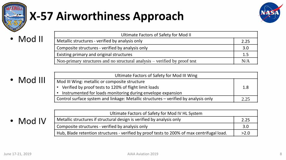
X-57 Airworthiness Approach
• Mod II
• Mod III
• Mod IV
AIAA Aviation 2019 8
Ultimate Factors of Safety for Mod II
Metallic structures - verified by analysis only 2.25
Composite structures - verified by analysis only 3.0
Existing primary and original structures 1.5
Non-primary structures and no structural analysis – verified by proof test N/A
Ultimate Factors of Safety for Mod III Wing
Mod III Wing: metallic or composite structure• Verified by proof tests to 120% of flight limit loads• Instrumented for loads monitoring during envelope expansion
1.8
Control surface system and linkage: Metallic structures – verified by analysis only 2.25
Ultimate Factors of Safety for Mod IV HL System
Metallic structures if structural design is verified by analysis only 2.25
Composite structures - verified by analysis only 3.0
Hub, Blade retention structures - verified by proof tests to 200% of max centrifugal load. >2.0
June 17-21, 2019
•

X-57 Mod II
Ultimate Factors of Safety for Mod II
Metallic structures - verified by analysis only 2.25
Composite structures - verified by analysis only 3.0
Existing primary and original structures 1.5
Non-primary structures and no structural analysis – verified by proof test N/A
•

Mod II Loads Requirements
• Due to the max gross weight increased, Mod II maneuver limit load factor will be reduced and limited to 3.4g
• The primary structures are designed for– Flight Maneuver and Ground loads– Emergence landing / Crash Loads: The items of
mass within cabin that could injure an occupant, will be secured to fuselage structure to withstand the 18g cash loads conditions.
• Cruise Motor, Motor Mount and Nacelle/Pylon are designed for– Flight Maneuver and Ground loads– Powerplant loads (Thrust, Torque, P-factor, and
Gyroscopic)
New metallic
structure
Exiting
structureDown, Nz 3.4 2.25 1.5 Maneuver loads
Forward, Nx -18 1 1 Crash loads
Sideward, Ny +/-4.5 1 1 Crash loadsUp, Nz -6 1 1 Crash loads
New metallic
structure
Exiting
structure
Down, Nz 3.4 2.25 1.5 Maneuver loads
Forward, Nx -3 2.25 1.5 Maneuver loads
Sideward, Ny -1.33 2.25 1.5 Maneuver loadsUp, Nz -2 2.25 1.5 Maneuver loads
Design Limit
Load Factor (g)
Factor of Safety
Condition
Design Limit
Load Factor (g)
Factor of SafetyCondition
Critical Load Cases for primary structure
X-57 Mod II VN Diagram
AIAA Aviation 2019 10June 17-21, 2019
•

Cruise Motor Design and Analysis
AIAA Aviation 2019 11
Design Loads• Flight maneuver loads• Ground & landing loads• Powerplant loads (applied at
the propeller CG• Max thrust• Max torque• P-factor loads• Gyroscopic loads
Stator: AL7075-T6
Rotor
Propeller Mount
Magnets
Cruise motor structure
Modal analysis: First Bending Mode 154Hz – 9240 RPM
Cruise motor design
June 17-21, 2019
•

Mod II Motor Mount Design
AIAA Aviation 2019 12
4130 Welded Stress Truss
Motor adapter
FEM AnalysisStatic, Buckling, and Modal analysis
Motor mount loads calibration testDevelop load equation for in-flight Torque and Thrust measurement
Strain Gages Instrumentation
Design Loads• Flight maneuver loads• Ground & landing loads• Powerplant loads
• Max thrust• Max torque• P-factor loads• Gyroscopic loads
Integration (Top View)
Motor Mount and Truss
June 17-21, 2019
•

X-57 Battery Integration
AIAA Aviation 2019
Contactor pallet (left and right)
BCM
Fwd Battery Mount
Battery Venting (3” dia)Hermetically seals battery smoke/eject from cabin volume
Aft (Cargo) Battery Mount
13
Design Loads• Flight maneuver loads• Crash loads
Battery Venting
June 17-21, 2019
•

TubeAdapter
Bulkhead FittingNose Fit(Proof test 100%)
Air Data Boom100600-01
X-57 Aircraft Modification
AIAA Aviation 2019 14
Air Data Probe
Per AC21-34 SHOULDER HARNESS - SAFETY BELT INSTALLATIONS & AC 43.13-2B Ch 9 SHOULDER HARNESS INSTALLATIONS:
Upgraded 4-point harness
Secondary Egress
Equipment Pallet (co-pilot seat)Cockpit Display
June 17-21, 2019
• I:
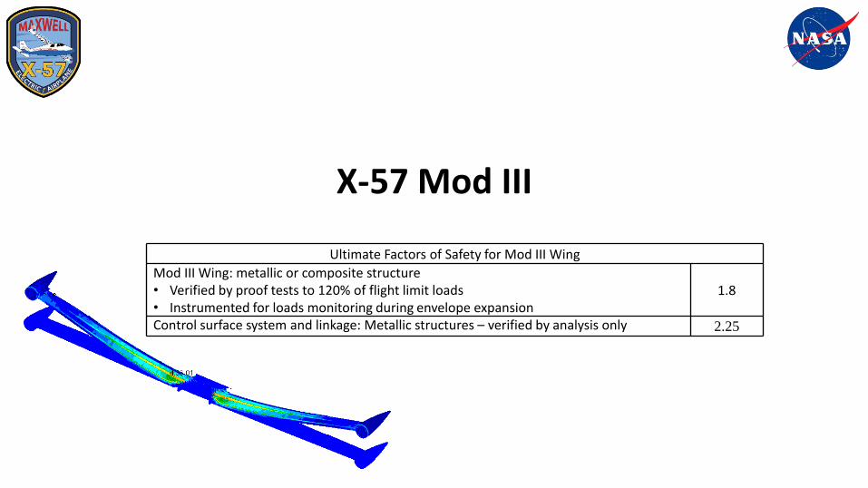
X-57 Mod III
Ultimate Factors of Safety for Mod III Wing
Mod III Wing: metallic or composite structure• Verified by proof tests to 120% of flight limit loads• Instrumented for loads monitoring during envelope expansion
1.8
Control surface system and linkage: Metallic structures – verified by analysis only 2.25
•

X-57 Wing Design
• Designed and Fabricated by Xperimental
• Composite: semi-monocoque wing
• Single and continuous main spar: responsible to carry normal and axial loads (shear and bending)
• Working skin: buckling free and responsible to carry torsional loads
• Front and rear spars used to receive external loads (nacelles and controls)
AIAA Aviation 2019 16June 17-21, 2019
.lfa;11 spar
From Spar
On, pair of f ront ribs for enl'h HL nnu ll,
Lending edge Lnpjoint
,\fain Biu d11ct
Jnsm11ne111arion duct
Front Spar Zshape Better Tors1011al box Hard pomt for HL nacelles "Bmf" stnke
.Mnln Spnr Cshnp, Easy fabncanon of a mono/itJ11c structure Pre-Pregfabricarion From ribs will act as stiffener for wwp deformation
RearSpnr Cshape
• 011, r,or rib for t!nl'h HL 11nc,11,
Closes the bock ton1on box • Hard poml for bell cranks and mfnon hmges
Cnrl>on Jibn skin wit I, U-iin PVC / oonr
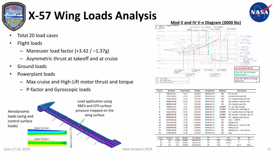
X-57 Wing Loads Analysis
• Total 20 load cases
• Flight loads
– Maneuver load factor (+3.42 / –1.37g)
– Asymmetric thrust at takeoff and at cruise
• Ground loads
• Powerplant loads
– Max cruise and High-Lift motor thrust and torque
– P-factor and Gyroscopic loads
AIAA Aviation 2019 17
Load application using RBE3 and CFD surface
pressure mapped on the wing surface
Mod II and IV V-n Diagram (3000 lbs)
Aerodynamic loads (wing and control surface loads)
June 17-21, 2019
X-S7 mod-4 v-n diagr:>m Zl21Rll.iU \ V • 3000 lb$. S • 66.67 s. r. ~ 'KEA!
U KEAS JOJKEAS
)_,_t; ---------------·-------·-------------
1~-0•-·vc•c.,., .. ~...... ,,.., ..... 1<190-
~ --·· ·-· ·-· """'· -·· ...,,. .......... _._ Case #
9
10
11
12
13
14
15
16
Airspeed
89kEAS (Vs) 152kEAS(Vc)
164kEAS(Va)
190kEAS(Vd)
190kEAS(Vd)
89kEAS(Vs)
1S2kEAS(Vc)
164kEAS(Va)
190kEAS(Vd )
190kEAS(Vd )
164kEAS(Va)
164kEAS(Va) 164kEAS(Va)
190kEAS(Vd )
190kEAS(Vd)
130kEAS(Vij
C·Llrf: 1.10
Load factor
+1.0
+2.9 1
+3.4 2
+3.42
-1.71
+LO
+2.91
+3.42
+3 .4 2
-1.71
+2.99
+2.28
+2.28
+2.28
+2.28
+2.00
Ca\e # Airs pe ed l oa d Weight
17 164 +2.565 13351N
18 164 +3 ,42 13351N
19 164 +2.S 13351N
Weight
133S! N 13351N
133S! N
13351N
13351N
13351N
133S! N
13351N
13351 N
13351N
13351N
13351N
13351N
133S! N
133S! N
13351N
CG position
4044 .8 1mm
4044 .8 1mm
4044 .81mm
CG position
4044.81mm 4044.81mm
4044.81mm
4044.81mm
4044.81mm
4044.81mm 4044.81mm
4044.81mm
4044.81mm
4044.81mm
4044.81mm
4044.81mm 4044.81mm
4044.81mm
4044.81mm
4044.81mm
Ah
Oft
Oft
Oft
•
Flap 30'" With Hl Pow, r (Mod IV)
Alt itude Description
Oft Vs - l g AS L
Oft Ve max ni due stall ASL
Oft Va - posit ive maneuver ASL
Oft Vd - pos it ive maneuver ASL
Oft Vd - negat ive gust ASL
15000ft Vs - l g high alt itude
15000ft Ve max nz due stall high alt.
15000ft Va - positive maneuver high alt.
15000ft Vd - pos it ive maneuver high alt.
15000ft Vd - negat ive gust high alt .
1927
1400 1S42
Oft Asym - 100/75
Oft Rolling at Va
Oft Roll ing at Va - max roll rate
Oft Rolling atVd
Oft Rolling at Vd - max roll rate
Oft Flap
376.25
318.75
a
My
261.S 104.6
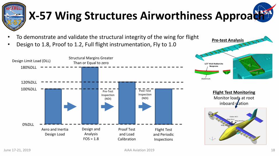
X-57 Wing Structures Airworthiness Approach
18
Flight Test Monitoring Monitor loads at root
inboard station
Aero and Inertia Design Load
Design and Analysis
FOS = 1.8
100%DLL
180%DLL
Design Limit Load (DLL)Structural Margins Greater
Than or Equal to zero
120%DLL
Proof Testand Load
Calibration
Flight Test and Periodic Inspections
0%DLL
Pre-Test Inspection
(NDI)
Post-Test Inspection
(NDI)
• To demonstrate and validate the structural integrity of the wing for flight• Design to 1.8, Proof to 1.2, Full flight instrumentation, Fly to 1.0
Pre-test Analysis
AIAA Aviation 2019June 17-21, 2019
•
• •

X-57 Wing Testing
• Proof and loads calibration testing
– Will be conducted at AFRC in August 2019
– Qualification test the wing structure to 120% Design Limit Load (DLL)
– Qualification test cruise motor mount hard points to 120% DLL (axial in-plane)
– Produce a database suitable for deriving wing load equations by applying a set of known loads and recording strain gage outputs
– Verify the control surfaces (flaps and ailerons) are free of binding while the wings are loaded to 100% DLL.
– Collect wing deflection measurement data for FEM model comparison and model tuning
• Ground Vibration Test (GVT)
– Wing on proof test fixture
– Identify the structural modes and the associated mode shapes as well as frequency and damping values of the wing before the integrated aircraft GVT
AIAA Aviation 2019 19
Aileron BellcrankActuator
Cruise Simulator Loading
Test RigJacks
X-57 Wing
June 17-21, 2019
•

Fuselage Wing Attachment Structural Analysis
• Asymmetric thrust at take-off load case is the critical load case for the fuselage wing attachment.
• Require new wing attachment and new doubler
• Existing fuselage FS set at 1.5, same as Tecnam FS
• All new hardware FS set at 2.25 (no-test)
AIAA Aviation 2019
Asymmetric Thrust at Take-Off Case
New Doubler0.08” thick6.75” long
6.75”
Riveted to sides only(14 places)
Fuselage Skin
New wing attachment
0.33” thick
0.1” thick
Drilled and tapped screws using Helicoil®
threaded inserts(8 places)
Existing FS Ult. 1.5 Al 6082-T6 Al 7050
New FS Ult. 2.25 Ftu (psi) 42,000 74,000
Fsu (psi) 27,000 43,000
MaterialsFactors of Safety
No-test FS
Inertia relief boundary conditions Full thrust one side + Half thrust other side + 2.0 x VS 1g ASL
20June 17-21, 2019
•
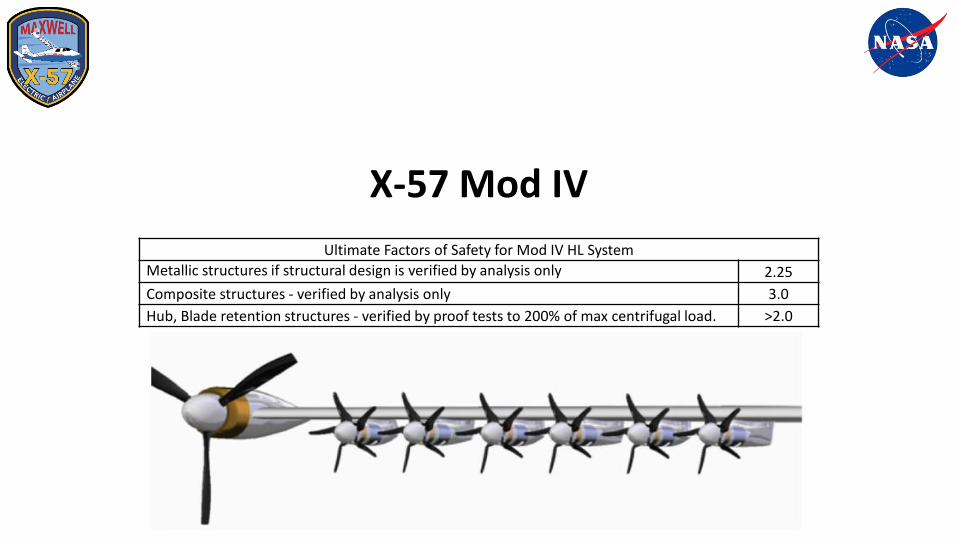
X-57 Mod IV
Ultimate Factors of Safety for Mod IV HL System
Metallic structures if structural design is verified by analysis only 2.25
Composite structures - verified by analysis only 3.0
Hub, Blade retention structures - verified by proof tests to 200% of max centrifugal load. >2.0
•

Mod IV High Lift Concept Overview
AIAA Aviation 2019 22
HL Exploded View
Blades fold back and “stow” onto Nacelle
Folding Propellers
HL Tail Nacelle
Structural Model
• PDR completed in April, 2019• Design Loads (Inertial, Thrust, Torque, Imbalance, P-factor,
Gyroscopic, etc)• Decoupled from motor operational dwell frequencies:
5460 RPM / 91 Hz.• To avoid coupling with wing flutter modes
June 17-21, 2019
•
Long Nacelle FEM Short Nacelle FEM
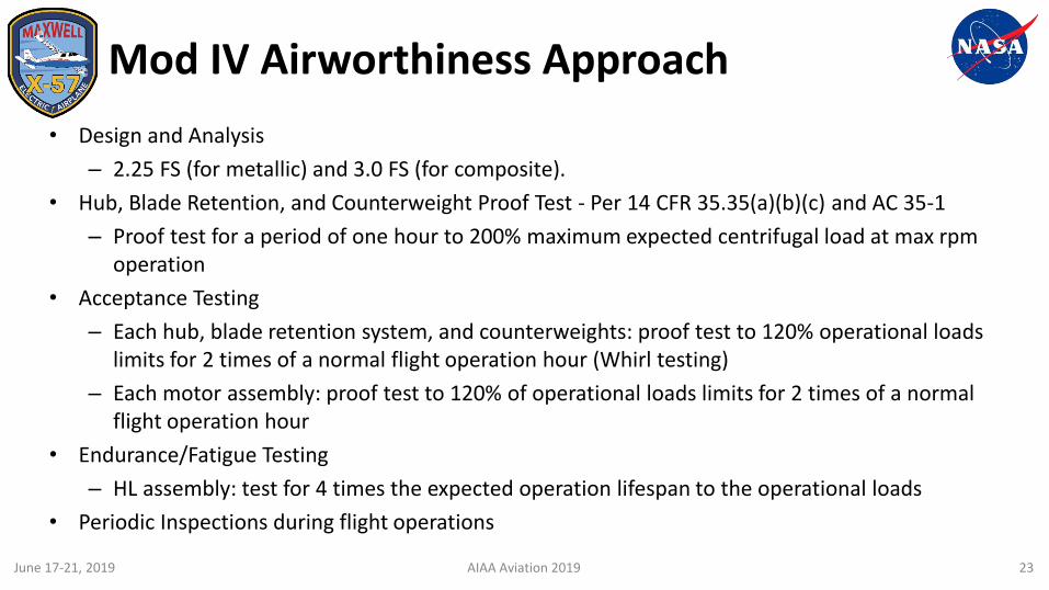
Mod IV Airworthiness Approach
• Design and Analysis
– 2.25 FS (for metallic) and 3.0 FS (for composite).
• Hub, Blade Retention, and Counterweight Proof Test - Per 14 CFR 35.35(a)(b)(c) and AC 35-1
– Proof test for a period of one hour to 200% maximum expected centrifugal load at max rpm operation
• Acceptance Testing
– Each hub, blade retention system, and counterweights: proof test to 120% operational loads limits for 2 times of a normal flight operation hour (Whirl testing)
– Each motor assembly: proof test to 120% of operational loads limits for 2 times of a normal flight operation hour
• Endurance/Fatigue Testing
– HL assembly: test for 4 times the expected operation lifespan to the operational loads
• Periodic Inspections during flight operations
AIAA Aviation 2019 23June 17-21, 2019
•

Aeroelasticity
•

Aeroelasticity: Airworthiness Approach
• Finite Element Model (FEM) development
– Structural and Aero models
• Flutter analyses
– Whirl Flutter: propeller/hub/motor/pylon assembly mounted to wing
– Classical Vehicle Flutter: Bending/Torsion coupling
• Ground Vibration Test (GVT) to measure natural modes, frequencies and structural damping
– Correlate structural model for final flutter analyses
– Conduct multiple GVTs (prop & hub, wing on proof test fixture, wing on fit-check fuselage) to reduce project risk by not waiting for the integrated aircraft GVT
• Flight flutter testing for envelope clearance
– Instrumentation distribution on aircraft
– Control room monitoringAIAA Aviation 2019 25
Soft Support (Bungee) Design for GVT
Support aircraft nose around NG
bulkhead
Support MLG axles by attaching bungee support beams to jacks
Wing on Proof Test Fixture GVT
Example: Cruise Prop/Hub GVT on Foam Soft Support
Component GVT
June 17-21, 2019
•

Thank You
X-57 Technical Document Portal (https://nasa.gov/x57/technical)
•