overview - used cisco liquidators · the cisco pa-8t-v.35, shown in figure 1-1 on page 1-2,...
TRANSCRIPT

PA-8T-V.35 Synchronous Serial PorOL-3563-03
C H A P T E R 1
OverviewThis chapter describes the V.35 synchronous serial port adapter (PA-8T-V35[=]) and contains the following sections:
• Port Adapter Overview, page 1-1
• Serial Interface Specifications, page 1-2
• LEDs, page 1-3
• Cables and Pinouts, page 1-4
• Port Adapter Slot Locations on the Supported Platforms, page 1-14
• Identifying Interface Addresses, page 1-21
Port Adapter OverviewThe Cisco PA-8T-V.35, shown in Figure 1-1 on page 1-2, provides up to eight synchronous serial interfaces for the chassis. The PA-8T-V.35 network interfaces provide a direct connection between the high-speed bus in the router and external networks. Each PA-8T-V.35 interface provides full-duplex (FDX) operation at T1 (1.544 Mbps) and E1 (2.048 Mbps) speeds. The V.35 interface is most commonly used in the United States and throughout Europe.
All eight PA-8T-V.35 interfaces connect to external networks through a single port that has a 200-pin, D-shell receptacle. You must use a V.35 compact serial cable to connect PA-8T-V.35 interfaces to an external data service unit (DSU) or channel service unit (CSU). The compact serial cable attached to the single receptacle determines the mode (DCE or DTE) for all eight interfaces.
Note Although the Cisco 7304 PCI Port Adapter Carrier Card in the Cisco 7304 router, Catalyst RSM/VIP2, the Catalyst 6000 family FlexWAN module, and the VIP support online insertion and removal (OIR), individual port adapters do not. To replace port adapters, you must first remove the Cisco 7304 PCI Port Adapter Carrier Card in the Cisco 7304 router, the Catalyst RSM/VIP2, the Catalyst 6000 family FlexWAN module, or the VIP from the chassis, and then replace port adapters as required.
Cisco 7100 series, Cisco 7200 series, Cisco uBR7200 series, Cisco 7301 routers, and Cisco 7401ASR routers support OIR of all port adapter types.
1-1t Adapter Installation and Configuration

Chapter 1 OverviewSerial Interface Specifications
Figure 1-1 PA-8T-V.35 Port Adapter—Faceplate View
All PA-8T-V.35 serial interfaces support non return to zero (NRZ) and non return to zero inverted (NRZI) format, and both 16-bit and 32-bit cyclic redundancy checks (CRCs). The default configuration is for NRZ format and 16-bit CRC. You can change the default settings with software commands.
There is no default mode or clock rate set on the PA-8T-V.35 serial ports, although an internal clock signal is present on all ports for data communications equipment (DCE) support. The internal clock allows you to perform local loopback tests without having to terminate the port or connect a cable. To use the port as a DCE interface, you must set the clock rate and connect a DCE compact serial cable. To use the port as a DTE interface, you need only connect a data terminal equipment (DTE) compact serial cable to the port. Because the serial adapter cables determine the mode and interface type, the PA-8T-V.35 interface becomes a DTE when a DTE cable is connected to it.
If a DTE cable is connected to a port with a clock rate set, the DTE ignores the clock rate and uses the external clock signal that is sent from the remote DCE. For a brief description of the clock rate command, see the “Configuring Timing (Clock) Signals” section on page 5-10. For complete command descriptions and instructions, refer to the publications listed in the “Related Documentation” section on page viii.
Serial Interface SpecificationsSerial signals can travel a limited distance at any given bit rate; generally, the slower the bit rate, the greater the distance. All serial signals are subject to distance limits beyond which a signal degrades significantly or is completely lost. Table 1-1 lists recommended transmission speeds and distances for V.35 serial interfaces. The recommended maximum rate for V.35 is 2.048 Mbps.
H73
76
EN
0 71 2 3 4 5 6SERIAL-V.35
Table 1-1 Recommended Transmission Speed Versus Distance
V.35 Distances
Rate (bps) Feet Meters
2400 4,100 1,250
4800 2,050 625
9600 1,025 312
19200 513 156
38400 256 78
56000 102 31
2048000 25 8
1-2PA-8T-V.35 Synchronous Serial Port Adapter Installation and Configuration
OL-3563-03

Chapter 1 OverviewLEDs
Note V.35 supports 2.048-Mbps rates without any problems; we do not recommend exceeding the above specifications for transmission speed versus distance. Do so at your own risk. The total aggregate bandwidth for the PA-8T-V.35 is 16 Mbps, which can be divided into 8 Mbps on two ports; 4 Mbps on four ports; or 2 Mbps on eight ports.
LEDsThe PA-8T-V.35 has one row of eight status LEDs (one for each port) and one enabled (EN) LED. (See Figure 1-2.) The green- and amber-colored LED for each port indicates port status.
Figure 1-2 LEDs on the PA-8T-V.35 Port Adapter—Horizontal Orientation
After system initialization, the enabled LED goes on to indicate that the port adapter has been enabled for operation.
The following conditions must be met before the PA-8T-V.35 is enabled:
• Port adapter is correctly connected to the backplane or midplane and receiving power.
• Valid system software image for the port adapter has been downloaded successfully.
• System recognizes the port adapter or PA-8T-V.35-equipped VIP, Catalyst RSM/VIP2, Catalyst 6000 family FlexWAN module, or Cisco 7304 PCI Port Adapter Carrier Card.
If any of the above conditions are not met, or if the initialization fails for other reasons, the enabled LED does not go on.
Table 1-2 lists port LED colors and indications.
H73
76
EN
0 71 2 3 4 5 6SERIAL-V.35
Table 1-2 PA-8T-V.35 Port LED Indications
LED Label Color State Function
0 through 7 Green On Port is initialized by the system (the software recognizes the hardware), and a V.35 compact serial cable is properly connected at the router end and the network end.
Green Flashing Port is sending and receiving data in half-duplex mode (Cisco 7200 series routers only).
1-3PA-8T-V.35 Synchronous Serial Port Adapter Installation and Configuration
OL-3563-03
Chapter 1 OverviewCables and Pinouts
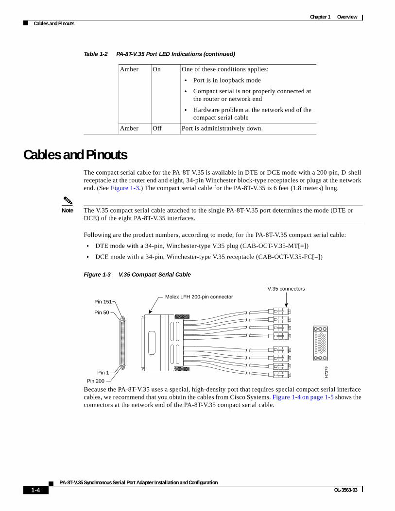
Cables and PinoutsThe compact serial cable for the PA-8T-V.35 is available in DTE or DCE mode with a 200-pin, D-shell receptacle at the router end and eight, 34-pin Winchester block-type receptacles or plugs at the network end. (See Figure 1-3.) The compact serial cable for the PA-8T-V.35 is 6 feet (1.8 meters) long.
Note The V.35 compact serial cable attached to the single PA-8T-V.35 port determines the mode (DTE or DCE) of the eight PA-8T-V.35 interfaces.
Following are the product numbers, according to mode, for the PA-8T-V.35 compact serial cable:
• DTE mode with a 34-pin, Winchester-type V.35 plug (CAB-OCT-V.35-MT[=])
• DCE mode with a 34-pin, Winchester-type V.35 receptacle (CAB-OCT-V.35-FC[=])
Figure 1-3 V.35 Compact Serial Cable
Because the PA-8T-V.35 uses a special, high-density port that requires special compact serial interface cables, we recommend that you obtain the cables from Cisco Systems. Figure 1-4 on page 1-5 shows the connectors at the network end of the PA-8T-V.35 compact serial cable.
Amber On One of these conditions applies:
• Port is in loopback mode
• Compact serial is not properly connected at the router or network end
• Hardware problem at the network end of the compact serial cable
Amber Off Port is administratively down.
Table 1-2 PA-8T-V.35 Port LED Indications (continued)
Pin 50
Pin 151
Pin 1
Pin 200
Molex LFH 200-pin connector
V.35 connectors
H73
79
1-4PA-8T-V.35 Synchronous Serial Port Adapter Installation and Configuration
OL-3563-03
Chapter 1 OverviewCables and Pinouts
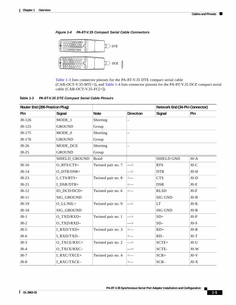
Figure 1-4 PA-8T-V.35 Compact Serial Cable Connectors
Table 1-3 lists connector pinouts for the PA-8T-V.35 DTE compact serial cable (CAB-OCT-V.35-MT[=]), and Table 1-4 lists connector pinouts for the PA-8T-V.35 DCE compact serial cable (CAB-OCT-V.35-FC[=]).
H16
16a
DTE
DCE
Table 1-3 PA-8T-V.35 DTE Compact Serial Cable Pinouts
Router End (200-Position Plug) Network End (34-Pin Connector)
Pin Signal Note Direction Signal Pin
J8-126
J8-125
MODE_1
GROUND
Shorting
Group
–
J8-175
J8-176
MODE_0
GROUND
Shorting
Group
–
J8-26
J8-25
MODE_DCE
GROUND
Shorting
Group
–
SHIELD_GROUND Braid SHIELD GND J0-A
J8-16
J8-14
O_RTS/CTS+
O_DTR/DSR+
Twisted pair no. 7 —>
—>
RTS
DTR
J0-C
J0-H
J8-23
J8-21
I_CTS/RTS+
I_DSR/DTR+
Twisted pair no. 8 <—
<—
CTS
DSR
J0-D
J0-E
J8-12
J8-11
IO_DCD/DCD+
SIG_GROUND
Twisted pair no. 6 <— RLSD
SIG GND
J0-F
J0-B
J8-19
J8-18
O_LL/NIL+
SIG_GROUND
Twisted pair no. 9 —> LT
SIG GND
J0-K
J0-B
J8-1
J8-2
O_TXD/RXD+
O_TXD/RXD–
Twisted pair no. 1 —>
—>
SD+
SD–
J0-P
J0-S
J8-5
J8-6
I_RXD/TXD+
I_RXD/TXD–
Twisted pair no. 3 <—
<—
RD+
RD–
J0-R
J0-T
J8-3
J8-4
O_TXCE/RXC+
O_TXCE/RXC–
Twisted pair no. 2 —>
—>
SCTE+
SCTE-
J0-U
J0-W
J8-7
J8-8
I_RXC/TXCE+
I_RXC/TXCE–
Twisted pair no. 4 <—
<—
SCR+
SCR–
J0-V
J0-X
1-5PA-8T-V.35 Synchronous Serial Port Adapter Installation and Configuration
OL-3563-03

Chapter 1 OverviewCables and Pinouts
J8-9
J8-10
IO_TXC/TXC+
IO_TXC/TXC–
Twisted pair no. 5 <—
<—
SCT+
SCT–
J0-Y
J0-AA
SHIELD_GROUND Braid SHIELD GND J1-A
J8-35
J8-37
O_RTS/CTS+
O_DTR/DSR+
Twisted pair no. 7 —>
—>
RTS
DTR
J1-C
J1-H
J8-28
J8-30
I_CTS/RTS+
I_DSR/DTR+
Twisted pair no. 8 <—
<—
CTS
DSR
J1-D
J1-E
J8-39
J8-40
IO_DCD/DCD+
SIG_GROUND
Twisted pair no. 6 <— RLSD
SIG GND
J1-F
J1-B
J8-32
J8-33
O_LL/NIL+
SIG_GROUND
Twisted pair no. 9 —> LT
SIG GND
J1-K
J1-B
J8-50
J8-49
O_TXD/RXD+
O_TXD/RXD–
Twisted pair no. 1 —>
—>
SD+
SD–
J1-P
J1-S
J8-46
J8-45
I_RXD/TXD+
I_RXD/TXD–
Twisted pair no. 3 <—
<—
RD+
RD–
J1-R
J1-T
J8-48
J8-47
O_TXCE/RXC+
O_TXCE/RXC–
Twisted pair no. 2 —>
—>
SCTE+
SCTE–
J1-U
J1-W
J8-44
J8-43
I_RXC/TXCE+
I_RXC/TXCE–
Twisted pair no. 4 <—
<—
SCR+
SCR–
J1-V
J1-X
J8-42
J8-41
IO_TXC/TXC+
IO_TXC/TXC–
Twisted pair no. 5 <—
<—
SCT+
SCT–
J1-Y
J1-AA
SHIELD_GROUND Braid SHIELD GND J2-A
J8-66
J8-64
O_RTS/CTS+
O_DTR/DSR+
Twisted pair no. 7 —>
—>
RTS
DTR
J2-C
J2-H
J8-73
J8-71
I_CTS/RTS+
I_DSR/DTR+
Twisted pair no. 8 <—
<—
CTS
DSR
J2-D
J2-E
J8-62
J8-61
IO_DCD/DCD+
SIG_GROUND
Twisted pair no. 6 <— RLSD
SIG GND
J2-F
J2-B
J8-69
J8-68
O_LL/NIL+
SIG_GROUND
Twisted pair no. 9 —> LT
SIG GND
J2-K
J2-B
J8-51
J8-52
O_TXD/RXD+
O_TXD/RXD–
Twisted pair no. 1 —>
—>
SD+
SD–
J2-P
J2-S
J8-55
J8-56
I_RXD/TXD+
I_RXD/TXD–
Twisted pair no. 3 <—
<—
RD+
RD–
J2-R
J2-T
Table 1-3 PA-8T-V.35 DTE Compact Serial Cable Pinouts (continued)
Router End (200-Position Plug) Network End (34-Pin Connector)
Pin Signal Note Direction Signal Pin
1-6PA-8T-V.35 Synchronous Serial Port Adapter Installation and Configuration
OL-3563-03

Chapter 1 OverviewCables and Pinouts
J8-53
J8-54
O_TXCE/RXC+
O_TXCE/RXC–
Twisted pair no. 2 —>
—>
SCTE+
SCTE–
J2-U
J2-W
J8-57
J8-58
I_RXC/TXCE+
I_RXC/TXCE–
Twisted pair no. 4 <—
<—
SCR+
SCR–
J2-V
J2-X
J8-59
J8-60
IO_TXC/TXC+
IO_TXC/TXC–
Twisted pair no. 5 <—
<—
SCT+
SCT–
J2-Y
J2-AA
SHIELD_GROUND Braid SHIELD GND J3-A
J8-85
J8-87
O_RTS/CTS+
O_DTR/DSR+
Twisted pair no. 7 —>
—>
RTS
DTR
J3-C
J3-H
J8-78
J8-80
I_CTS/RTS+
I_DSR/DTR+
Twisted pair no. 8 <—
<—
CTS
DSR
J3-D
J3-E
J8-89
J8-90
IO_DCD/DCD+
SIG_GROUND
Twisted pair no. 6 <— RLSD
SIG GND
J3-F
J3-B
J8-82
J8-83
O_LL/NIL+
SIG_GROUND
Twisted pair no. 9 —> LT
SIG GND
J3-K
J3-B
J8-100
J8-99
O_TXD/RXD+
O_TXD/RXD-
Twisted pair no. 1 —>
—>
SD+
SD–
J3-P
J3-S
J8-96
J8-95
I_RXD/TXD+
I_RXD/TXD–
Twisted pair no. 3 <—
<—
RD+
RD–
J3-R
J3-T
J8-98
J8-97
O_TXCE/RXC+
O_TXCE/RXC–
Twisted pair no. 2 —>
—>
SCTE+
SCTE–
J3-U
J3-W
J8-94
J8-93
I_RXC/TXCE+
I_RXC/TXCE–
Twisted pair no. 4 <—
<—
SCR+
SCR–
J3-V
J3-X
J8-92
J8-91
IO_TXC/TXC+
IO_TXC/TXC–
Twisted pair no. 5 <—
<—
SCT+
SCT–
J3-Y
J3-AA
SHIELD_GROUND Braid SHIELD GND J4-A
J8-116
J8-114
O_RTS/CTS+
O_DTR/DSR+
Twisted pair no. 7 —>
—>
RTS
DTR
J4-C
J4-H
J8-123
J8-121
I_CTS/RTS+
I_DSR/DTR+
Twisted pair no. 8 <—
<—
CTS
DSR
J4-D
J4-E
J8-112
J8-111
IO_DCD/DCD+
SIG_GROUND
Twisted pair no. 6 <— RLSD
SIG GND
J4-F
J4-B
J8-119
J8-118
O_LL/NIL+
SIG_GROUND
Twisted pair no. 9 —> LT
SIG GND
J4-K
J4-B
Table 1-3 PA-8T-V.35 DTE Compact Serial Cable Pinouts (continued)
Router End (200-Position Plug) Network End (34-Pin Connector)
Pin Signal Note Direction Signal Pin
1-7PA-8T-V.35 Synchronous Serial Port Adapter Installation and Configuration
OL-3563-03

Chapter 1 OverviewCables and Pinouts
J8-101
J8-102
O_TXD/RXD+
O_TXD/RXD–
Twisted pair no. 1 —>
—>
SD+
SD–
J4-P
J4-S
J8-105
J8-106
I_RXD/TXD+
I_RXD/TXD–
Twisted pair no. 3 <—
<—
RD+
RD–
J4-R
J4-T
J8-103
J8-104
O_TXCE/RXC+
O_TXCE/RXC–
Twisted pair no. 2 —>
—>
SCTE+
SCTE–
J4-U
J4-W
J8-107
J8-108
I_RXC/TXCE+
I_RXC/TXCE–
Twisted pair no. 4 <—
<—
SCR+
SCR–
J4-V
J4-X
J8-109
J8-110
IO_TXC/TXC+
IO_TXC/TXC–
Twisted pair no. 5 <—
<—
SCT+
SCT–
J4-Y
J4-AA
SHIELD_GROUND Braid SHIELD GND J5-A
J8-135
J8-137
O_RTS/CTS+
O_DTR/DSR+
Twisted pair no. 7 —>
—>
RTS
DTR
J5-C
J5-H
J8-128
J8-130
I_CTS/RTS+
I_DSR/DTR+
Twisted pair no. 8 <—
<—
CTS
DSR
J5-D
J5-E
J8-139
J8-140
IO_DCD/DCD+
SIG_GROUND
Twisted pair no. 6 <— RLSD
SIG GND
J5-F
J5-B
J8-132
J8-133
O_LL/NIL+
SIG_GROUND
Twisted pair no. 9 —> LT
SIG GND
J5-K
J5-B
J8-150
J8-149
O_TXD/RXD+
O_TXD/RXD–
Twisted pair no. 1 —>
—>
SD+
SD–
J5-P
J5-S
J8-146
J8-145
I_RXD/TXD+
I_RXD/TXD–
Twisted pair no. 3 <—
<—
RD+
RD–
J5-R
J5-T
J8-148
J8-147
O_TXCE/RXC+
O_TXCE/RXC–
Twisted pair no. 2 —>
—>
SCTE+
SCTE–
J5-U
J5-W
J8-144
J8-143
I_RXC/TXCE+
I_RXC/TXCE–
Twisted pair no. 4 <—
<—
SCR+
SCR–
J5-V
J5-X
J8-142
J8-141
IO_TXC/TXC+
IO_TXC/TXC–
Twisted pair no. 5 <—
<—
SCT+
SCT–
J5-Y
J5-AA
SHIELD_GROUND Braid SHIELD GND J6-A
J8-166
J8-164
O_RTS/CTS+
O_DTR/DSR+
Twisted pair no. 7 —>
—>
RTS
DTR
J6-C
J6-H
J8-173
J8-171
I_CTS/RTS+
I_DSR/DTR+
Twisted pair no. 8 <—
<—
CTS
DSR
J6-D
J6-E
Table 1-3 PA-8T-V.35 DTE Compact Serial Cable Pinouts (continued)
Router End (200-Position Plug) Network End (34-Pin Connector)
Pin Signal Note Direction Signal Pin
1-8PA-8T-V.35 Synchronous Serial Port Adapter Installation and Configuration
OL-3563-03

Chapter 1 OverviewCables and Pinouts
J8-162
J8-161
IO_DCD/DCD+
SIG_GROUND
Twisted pair no. 6 <— RLSD
SIG GND
J6-F
J6-B
J8-169
J8-168
O_LL/NIL+
SIG_GROUND
Twisted pair no. 9 —> LT
SIG GND
J6-K
J6-B
J8-151
J8-152
O_TXD/RXD+
O_TXD/RXD–
Twisted pair no. 1 —>
—>
SD+
SD–
J6-P
J6-S
J8-155
J8-156
I_RXD/TXD+
I_RXD/TXD–
Twisted pair no. 3 <—
<—
RD+
RD–
J6-R
J6-T
J8-153
J8-154
O_TXCE/RXC+
O_TXCE/RXC–
Twisted pair no. 2 —>
—>
SCTE+
SCTE–
J6-U
J6-W
J8-157
J8-158
I_RXC/TXCE+
I_RXC/TXCE–
Twisted pair no. 4 <—
<—
SCR+
SCR–
J6-V
J6-X
J8-159
J8-160
IO_TXC/TXC+
IO_TXC/TXC–
Twisted pair no. 5 <—
<—
SCT+
SCT–
J6-Y
J6-AA
SHIELD_GROUND Braid SHIELD GND J7-A
J8-185
J8-187
O_RTS/CTS+
O_DTR/DSR+
Twisted pair no. 7 —>
—>
RTS
DTR
J7-C
J7-H
J8-178
J8-180
I_CTS/RTS+
I_DSR/DTR+
Twisted pair no. 8 <—
<—
CTS
DSR
J7-D
J7-E
J8-189
J8-190
IO_DCD/DCD+
SIG_GROUND
Twisted pair no. 6 <— RLSD
SIG GND
J7-F
J7-B
J8-182
J8-183
O_LL/NIL+
SIG_GROUND
Twisted pair no. 9 —> LT
SIG GND
J7-K
J7-B
J8-200
J8-199
O_TXD/RXD+
O_TXD/RXD–
Twisted pair no. 1 —>
—>
SD+
SD–
J7-P
J7-S
J8-196
J8-195
I_RXD/TXD+
I_RXD/TXD–
Twisted pair no. 3 <—
<—
RD+
RD–
J7-R
J7-T
J8-198
J8-197
O_TXCE/RXC+
O_TXCE/RXC–
Twisted pair no. 2 —>
—>
SCTE+
SCTE–
J7-U
J7-W
J8-194
J8-193
I_RXC/TXCE+
I_RXC/TXCE–
Twisted pair no. 4 <—
<—
SCR+
SCR–
J7-V
J7-X
J8-192
J8-191
IO_TXC/TXC+
IO_TXC/TXC–
Twisted pair no. 5 <—
<—
SCT+
SCT–
J7-Y
J7-AA
Table 1-3 PA-8T-V.35 DTE Compact Serial Cable Pinouts (continued)
Router End (200-Position Plug) Network End (34-Pin Connector)
Pin Signal Note Direction Signal Pin
1-9PA-8T-V.35 Synchronous Serial Port Adapter Installation and Configuration
OL-3563-03

Chapter 1 OverviewCables and Pinouts
Table 1-4 PA-8T-V.35 DCE Compact Serial Cable Pinouts
Router End (200-Position Plug) Network End (34-Pin Connector)
Pin Signal Note Direction Signal Pin
J8-126
J8-125
MODE_1
GROUND
Shorting
Group
–
J8-175
J8-176
MODE_0
GROUND
Shorting
Group
–
SHIELD_GROUND Braid SHIELD GND J0-A
J8-23
J8-21
I_CTS/RTS+
I_DSR/DTR+
Twisted pair no. 8 <—
<—
RTS
DSR
J0-C
J0-H
J8-16
J8-14
O_RTS/CTS+
O_DTR/DSR+
Twisted pair no. 7 —>
—>
CTS
DTR
J0-D
J0-E
J8-12
J8-11
IO_DCD/DCD+
SIG_GROUND
Twisted pair no. 6 —> RLSD
SIG GND
J0-F
J0-B
J8-20
J8-18
I_NIL/LL+
SIG_GROUND
Twisted pair no. 9 <— LT
SIG GND
J0-K
J0-B
J8-5
J8-6
I_RXD/TXD+
I_RXD/TXD–
Twisted pair no. 3 <—
<—
SD+
SD–
J0-P
J0-S
J8-1
J8-2
O_TXD/RXD+
O_TXD/RXD–
Twisted pair no. 1 —>
—>
RD+
RD–
J0-R
J0-T
J8-7
J8-8
I_RXC/TXCE+
I_RXC/TXCE–
Twisted pair no. 4 <—
<—
SCTE+
SCTE–
J0-U
J0-W
J8-3
J8-4
O_TXCE/RXC+
O_TXCE/RXC–
Twisted pair no. 2 —>
—>
SCR+
SCR–
J0-V
J0-X
J8-9
J8-10
IO_TXC/TXC+
IO_TXC/TXC–
Twisted pair no. 5 —>
—>
SCT+
SCT–
J0-Y
J0-AA
SHIELD_GROUND Braid SHIELD GND J1-A
J8-28
J8-30
I_CTS/RTS+
I_DSR/DTR+
Twisted pair no. 8 <—
<—
RTS
DSR
J1-C
J1-H
J8-35
J8-37
O_RTS/CTS+
O_DTR/DSR+
Twisted pair no. 7 —>
—>
CTS
DTR
J1-D
J1-E
J8-39
J8-40
IO_DCD/DCD+
SIG_GROUND
Twisted pair no. 6 —> RLSD
SIG GND
J1-F
J1-B
J8-31
J8-33
I_NIL/LL+
SIG_GROUND
Twisted pair no. 9 <— LT
SIG GND
J1-K
J1-B
J8-46
J8-45
I_RXD/TXD+
I_RXD/TXD–
Twisted pair no. 3 <—
<—
SD+
SD–
J1-P
J1-S
1-10PA-8T-V.35 Synchronous Serial Port Adapter Installation and Configuration
OL-3563-03

Chapter 1 OverviewCables and Pinouts
J8-50
J8-49
O_TXD/RXD+
O_TXD/RXD–
Twisted pair no. 1 —>
—>
RD+
RD–
J1-R
J1-T
J8-44
J8-43
I_RXC/TXCE+
I_RXC/TXCE–
Twisted pair no. 4 <—
<—
SCTE+
SCTE–
J1-U
J1-W
J8-48
J8-47
O_TXCE/RXC+
O_TXCE/RXC–
Twisted pair no. 2 —>
—>
SCR+
SCR–
J1-V
J1-X
J8-42
J8-41
IO_TXC/TXC+
IO_TXC/TXC–
Twisted pair no. 5 —>
—>
SCT+
SCT–
J1-Y
J1-AA
SHIELD_GROUND Braid SHIELD GND J2-A
J8-73
J8-71
I_CTS/RTS+
I_DSR/DTR+
Twisted pair no. 8 <—
<—
RTS
DSR
J2-C
J2-H
J8-66
J8-64
O_RTS/CTS+
O_DTR/DSR+
Twisted pair no. 7 —>
—>
CTS
DTR
J2-D
J2-E
J8-62
J8-61
IO_DCD/DCD+
SIG_GROUND
Twisted pair no. 6 —> RLSD
SIG GND
J2-F
J2-B
J8-70
J8-68
I_NIL/LL+
SIG_GROUND
Twisted pair no. 9 <— LT
SIG GND
J2-K
J2-B
J8-55
J8-56
I_RXD/TXD+
I_RXD/TXD–
Twisted pair no. 3 <—
<—
SD+
SD–
J2-P
J2-S
J8-51
J8-52
O_TXD/RXD+
O_TXD/RXD–
Twisted pair no. 1 —>
—>
RD+
RD–
J2-R
J2-T
J8-57
J8-58
I_RXC/TXCE+
I_RXC/TXCE–
Twisted pair no. 4 <—
<—
SCTE+
SCTE–
J2-U
J2-W
J8-53
J8-54
O_TXCE/RXC+
O_TXCE/RXC–
Twisted pair no. 2 —>
—>
SCR+
SCR–
J2-V
J2-X
J8-59
J8-60
IO_TXC/TXC+
IO_TXC/TXC–
Twisted pair no. 5 —>
—>
SCT+
SCT–
J2-Y
J2-AA
SHIELD_GROUND Braid SHIELD GND J3-A
J8-78
J8-80
I_CTS/RTS+
I_DSR/DTR+
Twisted pair no. 8 <—
<—
RTS
DSR
J3-C
J3-H
J8-85
J8-87
O_RTS/CTS+
O_DTR/DSR+
Twisted pair no. 7 —>
—>
CTS
DTR
J3-D
J3-E
J8-89
J8-90
IO_DCD/DCD+
SIG_GROUND
Twisted pair no. 6 —> RLSD
SIG GND
J3-F
J3-B
Table 1-4 PA-8T-V.35 DCE Compact Serial Cable Pinouts (continued)
Router End (200-Position Plug) Network End (34-Pin Connector)
Pin Signal Note Direction Signal Pin
1-11PA-8T-V.35 Synchronous Serial Port Adapter Installation and Configuration
OL-3563-03
Chapter 1 OverviewCables and Pinouts
J8-81
J8-83
I_NIL/LL+
SIG_GROUND
Twisted pair no. 9 <— LT
SIG GND
J3-K
J3-B
J8-96
J8-95
I_RXD/TXD+
I_RXD/TXD–
Twisted pair no. 3 <—
<—
SD+
SD–
J3-P
J3-S
J8-100
J8-99
O_TXD/RXD+
O_TXD/RXD–
Twisted pair no. 1 —>
—>
RD+
RD–
J3-R
J3-T
J8-94
J8-93
I_RXC/TXCE+
I_RXC/TXCE–
Twisted pair no. 4 <—
<—
SCTE+
SCTE–
J3-U
J3-W
J8-98
J8-97
O_TXCE/RXC+
O_TXCE/RXC–
Twisted pair no. 2 —>
—>
SCR+
SCR–
J3-V
J3-X
J8-92
J8-91
IO_TXC/TXC+
IO_TXC/TXC–
Twisted pair no. 5 —>
—>
SCT+
SCT–
J3-Y
J3-AA
SHIELD_GROUND Braid SHIELD GND J4-A
J8-123
J8-121
I_CTS/RTS+
I_DSR/DTR+
Twisted pair no. 8 <—
<—
RTS
DSR
J4-C
J4-H
J8-116
J8-114
O_RTS/CTS+
O_DTR/DSR+
Twisted pair no. 7 —>
—>
CTS
DTR
J4-D
J4-E
J8-112
J8-111
IO_DCD/DCD+
SIG_GROUND
Twisted pair no. 6 —> RLSD
SIG GND
J4-F
J4-B
J8-120
J8-118
I_NIL/LL+
SIG_GROUND
Twisted pair no. 9 <— LT
SIG GND
J4-K
J4-B
J8-105
J8-106
I_RXD/TXD+
I_RXD/TXD–
Twisted pair no. 3 <—
<—
SD+
SD–
J4-P
J4-S
J8-101
J8-102
O_TXD/RXD+
O_TXD/RXD–
Twisted pair no. 1 —>
—>
RD+
RD–
J4-R
J4-T
J8-107
J8-108
I_RXC/TXCE+
I_RXC/TXCE–
Twisted pair no. 4 <—
<—
SCTE+
SCTE–
J4-U
J4-W
J8-103
J8-104
O_TXCE/RXC+
O_TXCE/RXC–
Twisted pair no. 2 —>
—>
SCR+
SCR–
J4-V
J4-X
J8-109
J8-110
IO_TXC/TXC+
IO_TXC/TXC–
Twisted pair no. 5 —>
—>
SCT+
SCT–
J4-Y
J4-AA
SHIELD_GROUND Braid SHIELD GND J5-A
J8-128
J8-130
I_CTS/RTS+
I_DSR/DTR+
Twisted pair no. 8 <—
<—
RTS
DSR
J5-C
J5-H
Table 1-4 PA-8T-V.35 DCE Compact Serial Cable Pinouts (continued)
Router End (200-Position Plug) Network End (34-Pin Connector)
Pin Signal Note Direction Signal Pin
1-12PA-8T-V.35 Synchronous Serial Port Adapter Installation and Configuration
OL-3563-03

Chapter 1 OverviewCables and Pinouts
J8-135
J8-137
O_RTS/CTS+
O_DTR/DSR+
Twisted pair no. 7 —>
—>
CTS
DTR
J5-D
J5-E
J8-139
J8-140
IO_DCD/DCD+
SIG_GROUND
Twisted pair no. 6 —> RLSD
SIG GND
J5-F
J5-B
J8-131
J8-133
I_NIL/LL+
SIG_GROUND
Twisted pair no. 9 <— LT
SIG GND
J5-K
J5-B
J8-146
J8-145
I_RXD/TXD+
I_RXD/TXD–
Twisted pair no. 3 <—
<—
SD+
SD–
J5-P
J5-S
J8-150
J8-149
O_TXD/RXD+
O_TXD/RXD–
Twisted pair no. 1 —>
—>
RD+
RD–
J5-R
J5-T
J8-144
J8-143
I_RXC/TXCE+
I_RXC/TXCE–
Twisted pair no. 4 <—
<—
SCTE+
SCTE–
J5-U
J5-W
J8-148
J8-147
O_TXCE/RXC+
O_TXCE/RXC–
Twisted pair no. 2 —>
—>
SCR+
SCR–
J5-V
J5-X
J8-142
J8-141
IO_TXC/TXC+
IO_TXC/TXC–
Twisted pair no. 5 —>
—>
SCT+
SCT–
J5-Y
J5-AA
SHIELD_GROUND Braid SHIELD GND J6-A
J8-173
J8-171
I_CTS/RTS+
I_DSR/DTR+
Twisted pair no. 8 <—
<—
RTS
DSR
J6-C
J6-H
J8-166
J8-164
O_RTS/CTS+
O_DTR/DSR+
Twisted pair no. 7 —>
—>
CTS
DTR
J6-D
J6-E
J8-162
J8-161
IO_DCD/DCD+
SIG_GROUND
Twisted pair no. 6 —> RLSD
SIG GND
J6-F
J6-B
J8-170
J8-168
I_NIL/LL+
SIG_GROUND
Twisted pair no. 9 <— LT
SIG GND
J6-K
J6-B
J8-155
J8-156
I_RXD/TXD+
I_RXD/TXD–
Twisted pair no. 3 <—
<—
SD+
SD–
J6-P
J6-S
J8-151
J8-152
O_TXD/RXD+
O_TXD/RXD–
Twisted pair no. 1 —>
—>
RD+
RD–
J6-R
J6-T
J8-157
J8-158
I_RXC/TXCE+
I_RXC/TXCE–
Twisted pair no. 4 <—
<—
SCTE+
SCTE–
J6-U
J6-W
J8-153
J8-154
O_TXCE/RXC+
O_TXCE/RXC–
Twisted pair no. 2 —>
—>
SCR+
SCR–
J6-V
J6-X
J8-159
J8-160
IO_TXC/TXC+
IO_TXC/TXC–
Twisted pair no. 5 —>
—>
SCT+
SCT–
J6-Y
J6-AA
Table 1-4 PA-8T-V.35 DCE Compact Serial Cable Pinouts (continued)
Router End (200-Position Plug) Network End (34-Pin Connector)
Pin Signal Note Direction Signal Pin
1-13PA-8T-V.35 Synchronous Serial Port Adapter Installation and Configuration
OL-3563-03
Chapter 1 OverviewPort Adapter Slot Locations on the Supported Platforms
Port Adapter Slot Locations on the Supported PlatformsThis section discusses port adapter slot locations on the supported platforms. The Illustrations that follow summarize slot locations on each platform:
• Catalyst RSM/VIP2 Slot Numbering, page 1-15
• Catalyst 6000 Family FlexWAN Module Slot Numbering, page 1-15
• Cisco 7100 Series Routers Slot Numbering, page 1-16
• Cisco 7200 Series and Cisco uBR7200 Series Routers Slot Numbering, page 1-17
• Cisco 7301 Router Slot Numbering, page 1-18
• Cisco 7304 PCI Port Adapter Carrier Card Slot Numbering, page 1-18
• Cisco 7401ASR Router Slot Numbering, page 1-19
• VIP Slot Numbering, page 1-20
SHIELD_GROUND Braid SHIELD GND J7-A
J8-178
J8-180
I_CTS/RTS+
I_DSR/DTR+
Twisted pair no. 8 <—
<—
RTS
DSR
J7-C
J7-H
J8-185
J8-187
O_RTS/CTS+
O_DTR/DSR+
Twisted pair no. 7 —>
—>
CTS
DTR
J7-D
J7-E
J8-189
J8-190
IO_DCD/DCD+
SIG_GROUND
Twisted pair no. 6 —> RLSD
SIG GND
J7-F
J7-B
J8-181
J8-183
I_NIL/LL+
SIG_GROUND
Twisted pair no. 9 <— LT
SIG GND
J7-K
J7-B
J8-196
J8-195
I_RXD/TXD+
I_RXD/TXD–
Twisted pair no. 3 <—
<—
SD+
SD–
J7-P
J7-S
J8-200
J8-199
O_TXD/RXD+
O_TXD/RXD–
Twisted pair no. 1 —>
—>
RD+
RD–
J7-R
J7-T
J8-194
J8-193
I_RXC/TXCE+
I_RXC/TXCE–
Twisted pair no. 4 <—
<—
SCTE+
SCTE–
J7-U
J7-W
J8-198
J8-197
O_TXCE/RXC+
O_TXCE/RXC–
Twisted pair no. 2 —>
—>
SCR+
SCR–
J7-V
J7-X
J8-192
J8-191
IO_TXC/TXC+
IO_TXC/TXC–
Twisted pair no. 5 —>
—>
SCT+
SCT–
J7-Y
J7-AA
Table 1-4 PA-8T-V.35 DCE Compact Serial Cable Pinouts (continued)
Router End (200-Position Plug) Network End (34-Pin Connector)
Pin Signal Note Direction Signal Pin
1-14PA-8T-V.35 Synchronous Serial Port Adapter Installation and Configuration
OL-3563-03

Chapter 1 OverviewPort Adapter Slot Locations on the Supported Platforms
Catalyst RSM/VIP2 Slot Numbering The Catalyst RSM/VIP2 can be installed in any slot except the top slots, which contain the supervisor engine. The Catalyst RSM/VIP2 in a Catalyst 5000 family switch does not use interface processor slot numbering; therefore, slots are not numbered in Figure 1-5. The PA-8T-V.35 can be installed into either port adapter slot 0 or slot 1 on a Catalyst RSM/VIP2. Figure 1-5 shows a Catalyst RSM/VIP2 with two port adapters installed.
Note The Catalyst 5500 switch has 13 slots. Slot 1 is reserved for the supervisor engine. If a redundant supervisor engine is used, it would go in slot 2; otherwise, slot 2 can be used for other modules. Slot 13 is a dedicated slot, reserved for the ATM switch processor (ASP) module. Refer to the Catalyst 5000 Series Route Switch Module Installation and Configuration Note for any additional slot restrictions for the Catalyst RSM/VIP2.
Figure 1-5 Catalyst 5000 Family Switch with Port Adapters Installed on Catalyst RSM/VIP2
Catalyst 6000 Family FlexWAN Module Slot Numbering The Catalyst 6000 family FlexWAN module can be installed in any slot except slot 1, which is reserved for the supervisor engine. The PA-8T-V.35 can be installed into either port adapter bay 0 or bay 1 on a FlexWAN module. Figure 1-6 shows a FlexWAN module with two blank port adapters installed.
Note Slot 1 is reserved for the supervisor engine. If a redundant supervisor engine is used, it would go in slot 2; otherwise, slot 2 can be used for other modules.
2792
4
UTPTXCHANNEL 1
AUX
CONSOLE
RX
TXCHANNEL 0
RX
SLOT 1
RESETPCMCIA
SLOT 0
CPU HALT
PCMICA
EJECT
STATUS
ROUTE SWITCH MODULE
ENABLED
VIP2 Route Switch Module
1-15PA-8T-V.35 Synchronous Serial Port Adapter Installation and Configuration
OL-3563-03
Chapter 1 OverviewPort Adapter Slot Locations on the Supported Platforms
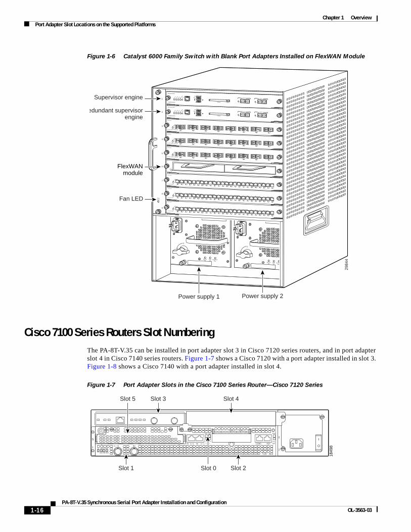
Figure 1-6 Catalyst 6000 Family Switch with Blank Port Adapters Installed on FlexWAN Module
Cisco 7100 Series Routers Slot Numbering The PA-8T-V.35 can be installed in port adapter slot 3 in Cisco 7120 series routers, and in port adapter slot 4 in Cisco 7140 series routers. Figure 1-7 shows a Cisco 7120 with a port adapter installed in slot 3. Figure 1-8 shows a Cisco 7140 with a port adapter installed in slot 4.
Figure 1-7 Port Adapter Slots in the Cisco 7100 Series Router—Cisco 7120 Series
2984
4
FANLED
INPUTOK
FANOK
OUTPUTFAIL
o
INPUTOK
FANOK
OUTPUTFAIL
o
1
2
3
4
5
6
7
8
9
SUPERVISOR I
WS-X6K-SUP1
STATUS
SYSTEM
ACTIVE
PWR M
GMT
RESET
CONSOLE
Switch Load 100%
1%
DTE/ DCE
PCMCIA EJECT
PORT 1
LINK
PORT 2
LINK
SUPERVISOR I
WS-X6K-SUP1
STATUS
SYSTEM
ACTIVE
PWR M
GMT
RESET
CONSOLE
Switch Load 100%
1%
DTE/ DCE
PCMCIA EJECT
PORT 1
LINK
PORT 2
LINK
8 PORT GIGABIT ETHERNET
WS-X6408
1
LINK
STATUS 2 3 4 5 6 7 8
LINK
LINK
LINK
LINK
LINK
LINK
LINK
8 PORT GIGABIT ETHERNET
WS-X6408
1
LINK
STATUS 2 3 4 5 6 7 8
LINK
LINK
LINK
LINK
LINK
LINK
LINK
8 PORT GIGABIT ETHERNET
WS-X6408
1
LINK
STATUS 2 3 4 5 6 7 8
LINK
LINK
LINK
LINK
LINK
LINK
LINK
24 PORT 100FX
WS-X6224
STATUS
24 PORT 100FX
WS-X6224
STATUS
24 PORT 100FX
WS-X6224
STATUS1
LINK
2
LINK
3
LINK
4
LINK
5
LINK
6
LINK
7
LINK
8
LINK
9
LINK
10
LINK
11
LINK
12
LINK
13
LINK
14
LINK
15
LINK
16
LINK
17
LINK
18
LINK
19
LINK
20
LINK
21
LINK
22
LINK
23
LINK
24
LINK
1
LINK
2
LINK
3
LINK
4
LINK
5
LINK
6
LINK
7
LINK
8
LINK
9
LINK
10
LINK
11
LINK
12
LINK
13
LINK
14
LINK
15
LINK
16
LINK
17
LINK
18
LINK
19
LINK
20
LINK
21
LINK
22
LINK
23
LINK
24
LINK
1
LINK
2
LINK
3
LINK
4
LINK
5
LINK
6
LINK
7
LINK
8
LINK
9
LINK
10
LINK
11
LINK
12
LINK
13
LINK
14
LINK
15
LINK
16
LINK
17
LINK
18
LINK
19
LINK
20
LINK
21
LINK
22
LINK
23
LINK
24
LINK
Power supply 2Power supply 1
Fan LED
FlexWANmodule
Supervisor engine
Redundant supervisorengine
STATUS
SLOT 0 SLOT 1
0
2
FE 0 / 0 FE AUX
7120 - AE3
RXTXE3RXEN
CEL CAR ALM
5
ICONS
ACT
0 / 1
ACT
LNK0
LNK1
PWR
SYSRDY
Slot 1 Slot 0
Slot 3 Slot 4Slot 5
1849
8
Slot 2
1-16PA-8T-V.35 Synchronous Serial Port Adapter Installation and Configuration
OL-3563-03

Chapter 1 OverviewPort Adapter Slot Locations on the Supported Platforms
Figure 1-8 Port Adapter Slots in the Cisco 7100 Series Router—Cisco 7140 Series
Cisco 7200 Series and Cisco uBR7200 Series Routers Slot NumberingFigure 1-9 shows a Cisco 7206 with port adapters installed. In the Cisco 7206, port adapter slot 1 is in the lower left position, and port adapter slot 6 is in the upper right position. (The Cisco 7202 and Cisco 7204 are not shown; however, the PA-8T-V.35 can be installed in any available port adapter slot.)
Figure 1-9 Port Adapter Slots in the Cisco 7206
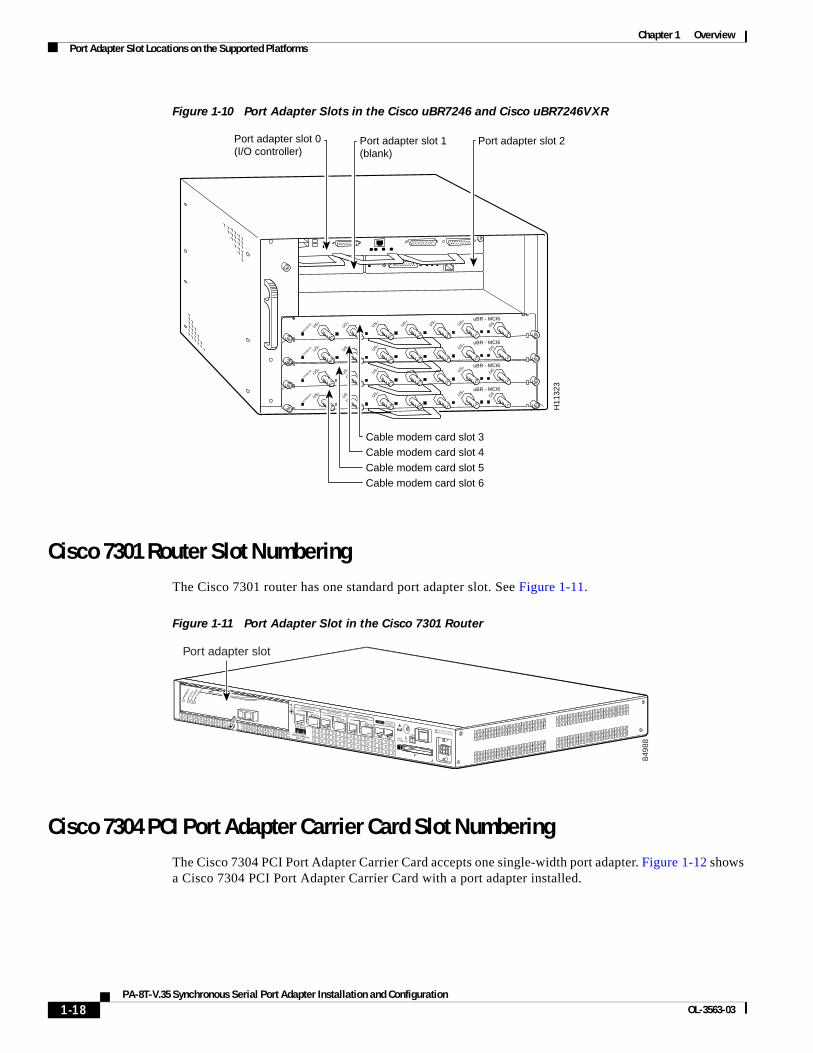
Figure 1-10 shows the slot numbering of port adapters in a Cisco uBR7246 and Cisco uBR7246VXR router. The port adapter slots are numbered slot 1 and slot 2 for the Cisco uBR7246 and Cisco uBR7246VXR router and slot 1 for the Cisco uBR7223. (Slot 0 is always reserved for the Fast Ethernet port on the I/O controller—if present.)
SLOT 0 SLOT 1
AC OK
DC OK
OTF
AC OK
DC OK
OTF
5
155 - MMRXRXEN
CEL CAR ALM
TXI155 - MM CONSFE 0 / 0 FE
ACT
0 / 1 AUX
0
2RX
7140 - 2MM3
RXEN
CEL CAR ALM
TX
ACT
LNK0
LNK1
PWR
SYSRDY
ENERROR
BOOTRESETSM-ISM
1849
9
Slot 1 Slot 0 Slot 2
Slot 4Slot 5 Slot 3
2832
9
2ETHERNET-10BFL
EN
RX
0 1 2 3 4TX RX TX RX TX RX TX RX TX
0
4
1
3
56
TOKEN RING
0 1 2 3
Cisco 7200Series
FAST ETHERNET INPUT/OUTPUT CONTROLLER
ENABLED
PCMCIA
EJECT
SLOT 0
SLOT 1
FE MII
EN
0 71 2 3 4 5 6SERIAL-V.35
ETHERNET 10BT
ENABLE
D
0 2
1 3
LINK
0 1 2 3
MII
EN RJ-45
EN
RJ-45
RJ-45
LINK
1O P
WR
OK
ENABLE
D
MII
LIN
K
RJ4
5FAST ETHERNET
0
Port adapter slot 5
Port adapter slot 3
Port adapter slot 1
Port adapter slot 6
Port adapter slot 4
Port adapter slot 2
Port adapter slot 0
1-17PA-8T-V.35 Synchronous Serial Port Adapter Installation and Configuration
OL-3563-03
Chapter 1 OverviewPort Adapter Slot Locations on the Supported Platforms
Figure 1-10 Port Adapter Slots in the Cisco uBR7246 and Cisco uBR7246VXR
Cisco 7301 Router Slot NumberingThe Cisco 7301 router has one standard port adapter slot. See Figure 1-11.
Figure 1-11 Port Adapter Slot in the Cisco 7301 Router
Cisco 7304 PCI Port Adapter Carrier Card Slot NumberingThe Cisco 7304 PCI Port Adapter Carrier Card accepts one single-width port adapter. Figure 1-12 shows a Cisco 7304 PCI Port Adapter Carrier Card with a port adapter installed.
ENABLED
DSuBR - MCI6
US USUS US0 1 2
5
ENABLED
DSuBR - MCI6
US USUS US0 1 2
5
ENABLED
DSuBR - MCI6
US USUS US
US US0 1 2 3 4 5
ENABLED
DSuBR - MCI6
US USUS US0 1 2
5
H11
323
Cable modem card slot 3Cable modem card slot 4
Cable modem card slot 5Cable modem card slot 6
Port adapter slot 0(I/O controller)
Port adapter slot 1 (blank)
Port adapter slot 2
ALARM
RJ45 ENLINK
TXRX
GBIC
GIGABIT ETHERNET 0/2
CISCO 7400SERIESCISCO 7411
SLOT 1
CONSOLEAUX
COMPACTFLASH STATUS
100-240V, 2A, 50/60 Hz24V=9A, 48 - 60V=5A
RJ45 ENLINK
TXRX
GBIC
GIGABIT ETHERNET 0/1
RJ45 ENLINK
TXRX
GBIC
GIGABIT ETHERNET 0/0
ENAB
LED
RX CE
LLS
RX CA
RRIER
RX AL
ARM
ATM
8498
8Port adapter slot
1-18PA-8T-V.35 Synchronous Serial Port Adapter Installation and Configuration
OL-3563-03

Chapter 1 OverviewPort Adapter Slot Locations on the Supported Platforms
Figure 1-12 Cisco 7304 PCI Port Adapter Carrier Card—Port Adapter Installed
The Cisco 7304 PCI Port Adapter Carrier Card installs in Cisco 7304 router module slots 2 through 5. See Figure 1-13 for module slot numbering on a Cisco 7304 router.
Figure 1-13 Module Slots on the Cisco 7304 Router
Cisco 7401ASR Router Slot NumberingFigure 1-14 shows the front view of a Cisco 7401ASR router with a port adapter installed. There is only one port adapter slot in a Cisco 7401ASR router.
84
65
3
7300-CC-PA
OIRSTATUS
7300 PA CARRIER
ENAB
LED
RX CE
LLS
RX CA
RRIER
RX AL
ARM
ATM
TX
9K-10C48
1-PORT OC48 POS w/ SMSR
OIR
STATUS
RX
OIR
STATUS
9K-40C3/POS-MM
4-PORT OC3 POS w/ MM
OIR
STATUS
CARRIER/ALARM
0
ACTIVE/LOOPBACK
12
3
CARRIER/ALARM ACTIVE/LOOPBACK CARRIER/ALARM ACTIVE/LOOPBACK
7300-2OC3ATM-MM
2-PORT OC3 ATM MM
OIR
STATUS
0 RXTX
1 RXTX
7055
0Slot 1
Slot 0
Slot 2
Slot 3
Slot 4
Slot 5
1-19PA-8T-V.35 Synchronous Serial Port Adapter Installation and Configuration
OL-3563-03
Chapter 1 OverviewPort Adapter Slot Locations on the Supported Platforms
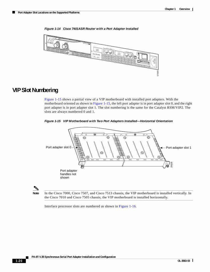
Figure 1-14 Cisco 7401ASR Router with a Port Adapter Installed
VIP Slot NumberingFigure 1-15 shows a partial view of a VIP motherboard with installed port adapters. With the motherboard oriented as shown in Figure 1-15, the left port adapter is in port adapter slot 0, and the right port adapter is in port adapter slot 1. The slot numbering is the same for the Catalyst RSM/VIP2. The slots are always numbered 0 and 1.
Figure 1-15 VIP Motherboard with Two Port Adapters Installed—Horizontal Orientation
Note In the Cisco 7000, Cisco 7507, and Cisco 7513 chassis, the VIP motherboard is installed vertically. In the Cisco 7010 and Cisco 7505 chassis, the VIP motherboard is installed horizontally.
Interface processor slots are numbered as shown in Figure 1-16.
5768
0
ENAB
LED
RX CE
LLS
RX CA
RRIER
RX AL
ARM
TX
RX ENHANCED ATM
2932
8
Port adapter slot 0 Port adapter slot 1
Port adapterhandles notshown
1-20PA-8T-V.35 Synchronous Serial Port Adapter Installation and Configuration
OL-3563-03

Chapter 1 OverviewIdentifying Interface Addresses
Figure 1-16 Interface Slot Numbers—Cisco 7505 shown
Identifying Interface Addresses This section describes how to identify interface addresses for the PA-8T-V.35 in supported platforms. Interface addresses specify the actual physical location of each interface on a router or switch.
Interfaces on the PA-8T-V.35 installed in a router maintain the same address regardless of whether other port adapters are installed or removed. However, when you move a port adapter to a different slot, the first number in the interface address changes to reflect the new port adapter slot number.
Interfaces on a PA-8T-V.35 installed in a Catalyst 6000 family FlexWAN module or a VIP maintain the same address regardless of whether other interface processors are installed or removed. However, when you move a Catalyst 6000 family FlexWAN module or a VIP to a different slot, the interface processor slot number changes to reflect the new interface processor slot.
Note Interface ports are numbered from left to right starting with 0.
Table 1-5 explains how to identify interface addresses.
2961
9
Slot 0
Slot 1
Slot 2
Slot 3
Interface processorslots
EJECT
SLOT 0SLO
T 1
NORMAL CPU HALT
RESET
CONSOLE
ROUTE SWITCH PROCESSOR
VIP in interface processor slot 3
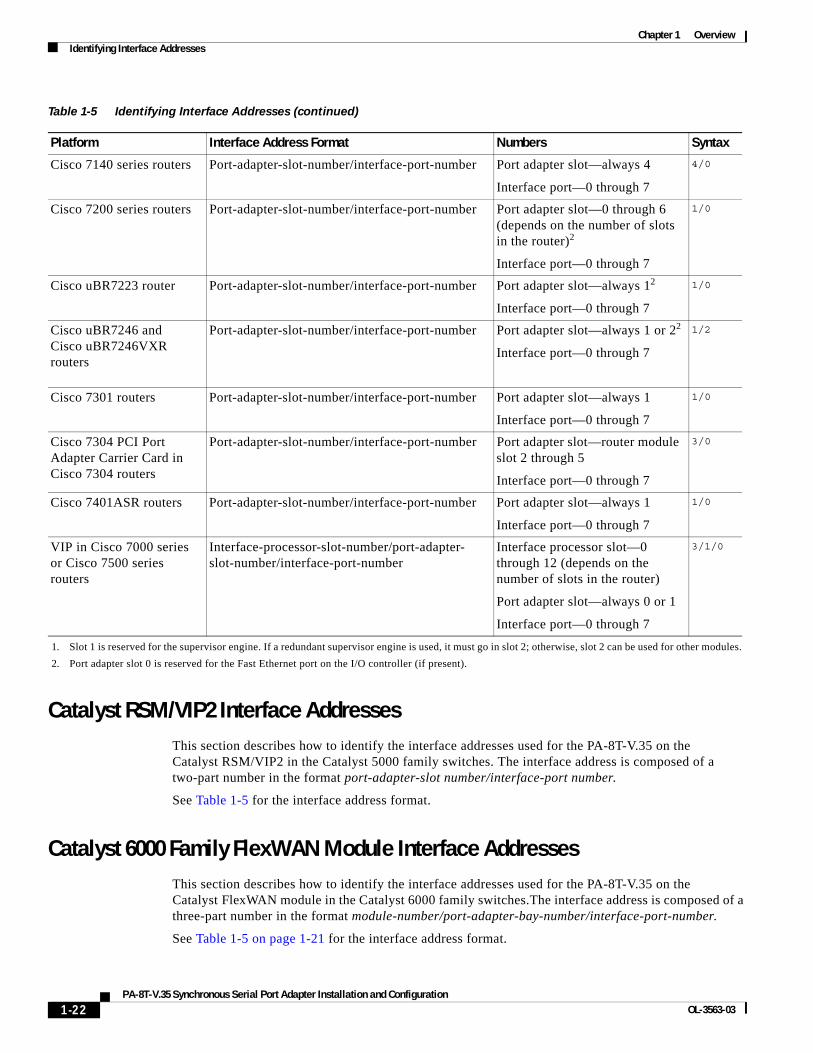
Table 1-5 Identifying Interface Addresses
Platform Interface Address Format Numbers Syntax
Catalyst RSM/VIP2 in Catalyst 5000 family switches
Port-adapter-slot-number/interface-port-number Port adapter slot—always 0 or 1
Interface port—0 through 7
0/1
Catalyst 6000 family FlexWAN module in Catalyst 6000 family switches
Module-slot-number/port-adapter-bay-number/interface-port-number
Module slot number—21 through 6 or 9 (depending on the number of slots in the switch)
Port adapter bay—always 0 or 1
Interface port—0 through 7
3/0/0
Cisco 7120 series routers Port-adapter-slot-number/interface-port-number Port adapter slot—always 3
Interface port—0 through 7
3/1
1-21PA-8T-V.35 Synchronous Serial Port Adapter Installation and Configuration
OL-3563-03
Chapter 1 OverviewIdentifying Interface Addresses
Catalyst RSM/VIP2 Interface AddressesThis section describes how to identify the interface addresses used for the PA-8T-V.35 on the Catalyst RSM/VIP2 in the Catalyst 5000 family switches. The interface address is composed of a two-part number in the format port-adapter-slot number/interface-port number.
See Table 1-5 for the interface address format.
Catalyst 6000 Family FlexWAN Module Interface AddressesThis section describes how to identify the interface addresses used for the PA-8T-V.35 on the Catalyst FlexWAN module in the Catalyst 6000 family switches.The interface address is composed of a three-part number in the format module-number/port-adapter-bay-number/interface-port-number.
See Table 1-5 on page 1-21 for the interface address format.
Cisco 7140 series routers Port-adapter-slot-number/interface-port-number Port adapter slot—always 4
Interface port—0 through 7
4/0
Cisco 7200 series routers Port-adapter-slot-number/interface-port-number Port adapter slot—0 through 6 (depends on the number of slots in the router)2
Interface port—0 through 7
1/0
Cisco uBR7223 router Port-adapter-slot-number/interface-port-number Port adapter slot—always 12
Interface port—0 through 7
1/0
Cisco uBR7246 and Cisco uBR7246VXR routers
Port-adapter-slot-number/interface-port-number Port adapter slot—always 1 or 22
Interface port—0 through 7
1/2
Cisco 7301 routers Port-adapter-slot-number/interface-port-number Port adapter slot—always 1
Interface port—0 through 7
1/0
Cisco 7304 PCI Port Adapter Carrier Card in Cisco 7304 routers
Port-adapter-slot-number/interface-port-number Port adapter slot—router module slot 2 through 5
Interface port—0 through 7
3/0
Cisco 7401ASR routers Port-adapter-slot-number/interface-port-number Port adapter slot—always 1
Interface port—0 through 7
1/0
VIP in Cisco 7000 series or Cisco 7500 series routers
Interface-processor-slot-number/port-adapter-slot-number/interface-port-number
Interface processor slot—0 through 12 (depends on the number of slots in the router)
Port adapter slot—always 0 or 1
Interface port—0 through 7
3/1/0
1. Slot 1 is reserved for the supervisor engine. If a redundant supervisor engine is used, it must go in slot 2; otherwise, slot 2 can be used for other modules.
2. Port adapter slot 0 is reserved for the Fast Ethernet port on the I/O controller (if present).
Table 1-5 Identifying Interface Addresses (continued)
Platform Interface Address Format Numbers Syntax
1-22PA-8T-V.35 Synchronous Serial Port Adapter Installation and Configuration
OL-3563-03

Chapter 1 OverviewIdentifying Interface Addresses
If the FlexWAN module is inserted in module slot 3, then the interface addresses of the PA-8T-V.35 are 3/0/0 through 3/0/7 (module slot 3, port adapter bay 0, and interfaces 0 through 7). If the port adapter was in port adapter bay 1 on the FlexWAN module, these same interface addresses would be numbered 3/1/0 through 3/1/7.
Note If you remove the FlexWAN module with the PA-8T-V.35 from module slot 3 and install it in module slot 6, the interface addresses become 6/0/0 through 6/0/7.
Note The FlexWAN module physical port address uses a zero- (0-) based port address, which differs from the conventional Catalyst 6000 family one- (1-) based port address.
Cisco 7100 Series Routers Interface AddressesThis section describes how to identify the interface addresses used for the PA-8T-V.35 in Cisco 7100 series routers. The interface address is composed of a two-part number in the format port-adapter-slot-number/interface-port-number. See Table 1-5 for the interface address format.
Cisco 7200 Series and Cisco uBR7200 Series Routers Interface Addresses This section describes how to identify the interface addresses used for the PA-8T-V.35 in Cisco 7200 series routers or Cisco uBR7200 series routers. The interface address is composed of a two-part number in the format port-adapter-slot-number/interface-port-number. See Table 1-5 for the interface address format.
In Cisco 7200 series routers, port adapter slots are numbered from the lower left to the upper right, beginning with port adapter slot 1 and continuing through port adapter slot 2 for the Cisco 7202, slot 4 for the Cisco 7204 and Cisco 7204VXR, and slot 6 for the Cisco 7206 and Cisco 7206VXR. (Port adapter slot 0 is reserved for the optional Fast Ethernet port on the I/O controller—if present.)
The interface addresses of the interfaces on the PA-8T-V.35 in port adapter slot 1 are 1/0 through 1/7 (port adapter slot 1 and interfaces 0 through 7). If the PA-8T-V.35 was in port adapter slot 4, these same interfaces would be numbered 4/0 through 4/7 (port adapter slot 4 and interfaces 0 through 7).
In Cisco uBR7200 series routers, port adapter slots are numbered slot 1 and slot 2 for the Cisco uBR7246 and Cisco uBR7246VXR and slot 1 for the Cisco uBR7223. (Slot 0 is always reserved for the Fast Ethernet port on the I/O controller—if present.) The individual interfaces always begin with 0. The number of additional interfaces depends on the number of interface ports on a port adapter.
The interface addresses of the interfaces on a PA-8T-V.35 in port adapter slot 2 are 2/0 and 2/1 (port adapter slot 2 and interfaces 0 and 1). If the PA-8T-V.35 was in port adapter slot 1, these same interfaces would be numbered 1/0 and 1/1 (port adapter slot 1 and interfaces 0 and 1).
Cisco 7301 Router Interface AddressesThis section describes how to identify the interface addresses used for the Cisco PA-8T-V.35 port adapter in Cisco 7301 router. The interface address is composed of a two-part number in the format port-adapter-slot-number/interface-port-number. See Table 1-5 on page 1-21 for the interface address format.
1-23PA-8T-V.35 Synchronous Serial Port Adapter Installation and Configuration
OL-3563-03

Chapter 1 OverviewIdentifying Interface Addresses
Cisco 7304 PCI Port Adapter Carrier Card Interface AddressesThis section describes how to identify the interface addresses used for the PA-8T-V.35 in the Cisco 7304 PCI Port Adapter Carrier Card in Cisco 7304 routers. The interface address is made of a two-part number in the format port-adapter-slot-number/interface-port-number.
The Cisco 7304 PCI Port Adapter Carrier Card installs into Cisco 7304 router module slots 2 through 5 (See Figure 1-13.) The port-adapter-slot-number is the Cisco 7304 router module slot number. For example, the interface address of port 0 on a PA-8T-V.35, in which the Cisco 7304 PCI Port Adapter Carrier Card is installed in Cisco 7304 router module slot 3, would be numbered 3/0.
Cisco 7401ASR Router Interface AddressesThis section describes how to identify the interface addresses used for the PA-8T-V.35 in the Cisco 7401ASR router. In the Cisco 7401ASR router, slot 1 is the port adapter slot you use for the PA-8T-V.35. The interface address is composed of a two-part number in the format port-adpater-slot-number/interface-port-number. See Table 1-5 on page 1-21 for the interface address format.
VIP Interface Addresses This section describes how to identify the interface addresses used for the PA-8T-V.35 on a VIP in Cisco 7000 series and Cisco 7500 series routers.
Note Although the processor slots in the 7-slot Cisco 7000 and Cisco 7507 and the 13-slot Cisco 7513 and Cisco 7576 are vertically oriented and those in the 5-slot Cisco 7010 and Cisco 7505 are horizontally oriented, all Cisco 7000 series and Cisco 7500 series routers use the same method for slot and port numbering.
See Table 1-5 for the interface address format. The interface address is composed of a three-part number in the format interface-processor-slot-number/port-adapter-slot-number/interface-port-number.
If the VIP is inserted in interface processor slot 3, then the interface addresses of the PA-8T-V.35 are 3/1/0 through 3/1/7 (interface processor slot 3, port adapter slot 1, and interfaces 0 through 7). If the port adapter was in port adapter slot 0 on the VIP, these same interface addresses would be numbered 3/0/0 through 3/0/7.
Note If you remove the VIP with the PA-8T-V.35 (shown in Figure 1-16 on page 1-21) from interface processor slot 3 and install it in interface processor slot 2, the interface addresses become 2/1/0 through 2/1/7.
1-24PA-8T-V.35 Synchronous Serial Port Adapter Installation and Configuration
OL-3563-03