owner's and installation manual eod leveler owner's & installation manual page 4 issue...
TRANSCRIPT
OWNER'S AND INSTALLATION
MANUAL
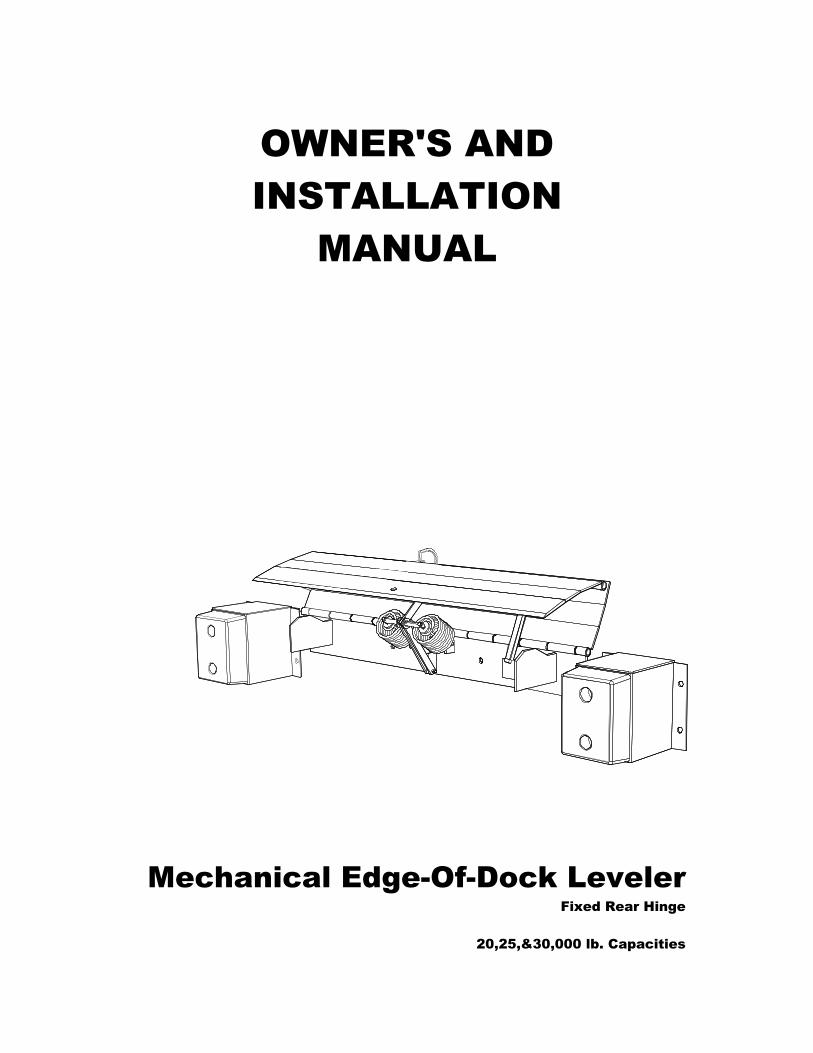
Mechanical Edge-Of-Dock Leveler Fixed Rear Hinge
20,25,&30,000 lb. Capacities

Mechanical EOD Leveler Owner's & Installation Manual
Issue Date: 06/21/05 (Part # 411-253) Page 1
TABLE OF CONTENTS 1. Introduction ......................................................................................................................................3
2. Receipt Inspection............................................................................................................................3
3. Installation Diagram - Mechanical EOD Dock Leveler.....................................................................4
4. Installation Instructions.....................................................................................................................5
4.1 Final Inspection ......................................................................................................................7 4.2 Installation Types ...................................................................................................................7
5. Routine Servicing And Maintenance..............................................................................................11
6. Component Identification ...............................................................................................................11
7. Operator Daily Inspection...............................................................................................................12
8. Planned Maintenance ....................................................................................................................12
9. Planned Maintenance Intervals......................................................................................................13
9.1 Maintenance Sequence........................................................................................................13 10. Safety Information ..........................................................................................................................14
10.1 General.................................................................................................................................14 10.2 Safety Signs And Safety Messages .....................................................................................15 10.3 General Safety Rules ...........................................................................................................16 10.4 Safety Procedures................................................................................................................17
11. The Mechanical Edge of Dock Leveler - Functional Description ...................................................18
12. Operator Maintenance And Care ...................................................................................................19
12.1 Daily Safety Inspection.........................................................................................................19 12.2 Visual Checks.......................................................................................................................19 12.3 Operator's Daily Check List..................................................................................................21 12.4 Operating Hazards ...............................................................................................................22
13. Before Operating The Dock Leveler ..............................................................................................25
13.1 Load Handling ......................................................................................................................25 13.2 Traveling With A Load..........................................................................................................25
14. Operating Instructions – Typical ....................................................................................................26
15. Operating Procedures - Pictorials ..................................................................................................28
16. Trouble Shooting............................................................................................................................32

Mechanical EOD Leveler Owner's & Installation Manual
Page 2 Issue Date: 06/21/05 (Part # 411-253)
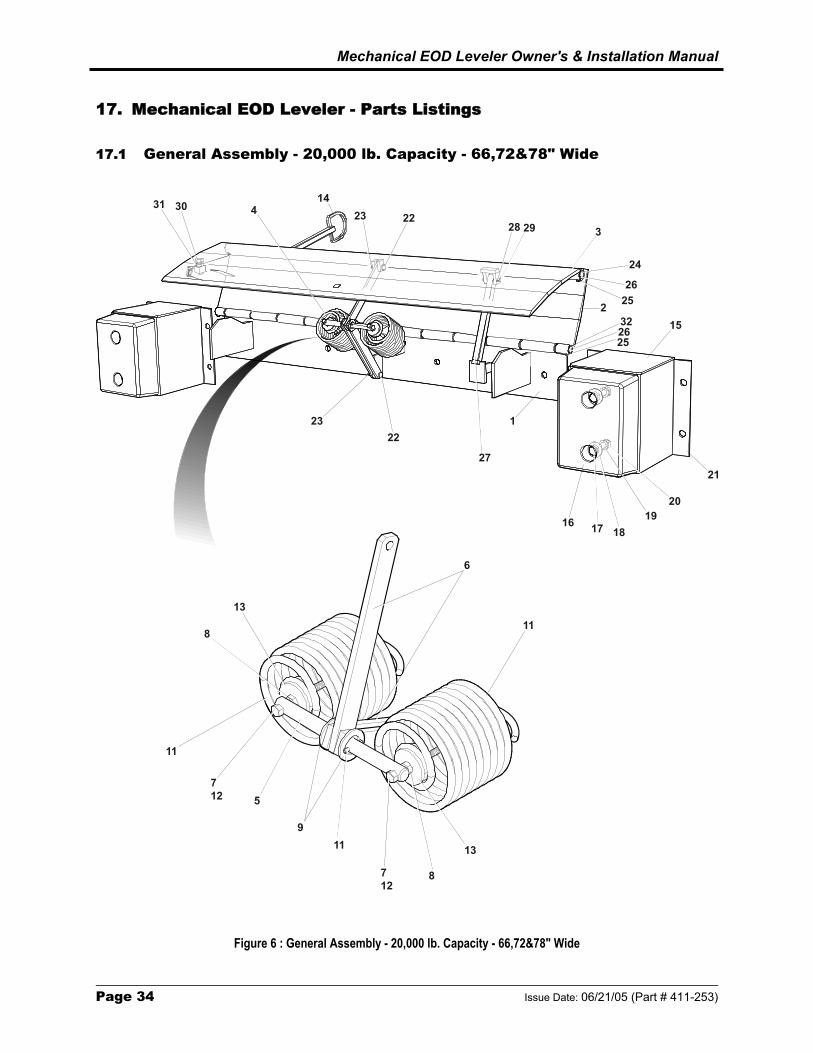
17. Mechanical EOD Leveler - Parts Listings ......................................................................................34
17.1 General Assembly - 20,000 lb. Capacity - 66,72&78" Wide ................................................34 17.2 General Assembly - 25,000 lb. Capacity - 66,72&78" Wide ................................................36 17.3 General Assembly - 30,000 lb. Capacity - 66&72" Wide......................................................38 17.4 General Assembly - 20,25,&30,000 lb. Capacity - 78&83" Wide .........................................40
18. Service / Maintenance History .......................................................................................................42
19. Warranty Policy ..............................................................................................................................43

Mechanical EOD Leveler Owner's & Installation Manual
Issue Date: 06/21/05 (Part # 411-253) Page 3
1. Introduction Read and understand these instructions before commencing work. Responsibilities:
The individuals assigned to perform the installation of the equipment are responsible for doing so in compliance with instructions contained herein. Date of Issue: 06/21/05, Part #411-253
Assumptions: The individuals responsible for performing these instructions are capable and experienced with installing this type of equipment.
2. Receipt Inspection
This equipment has been thoroughly inspected prior to leaving the factory. The equipment should be thoroughly checked for damage or loss occurring in transit, before accepting delivery or installing.
IMPORTANT! : IF ANY DAMAGE OR LOSS IS EVIDENT, A CLAIM MUST BE MADE AGAINST THE CARRIER.

Mechanical EOD Leveler Owner's & Installation Manual
Page 4 Issue Date: 06/21/05 (Part # 411-253)
3. Installation Diagram - Mechanical EOD Dock Leveler
CURBANGLE
VERTICAL WELD(BOTH ENDS)
BACKFRAME
BUMPER ANDEXTENSIONBRACKET
CURBANGLE
PLUG WELDTO CURB ANGLE
5/32” [4 mm]
BACKFRAME
1/4”ADJACENT TOHINGE SPOOLS
LOCATE AND DRILL 5/8” HOLE INTO CONCRETE
INSTALL (12) - 5/8” X 6” CONCRETE WEDGE ANCHORS
Figure 1 : Mechanical Edge-of-Dock Leveler Installation
Mechanical EOD Leveler Owner's & Installation Manual
Issue Date: 06/21/05 (Part # 411-253) Page 5
4. Installation Instructions
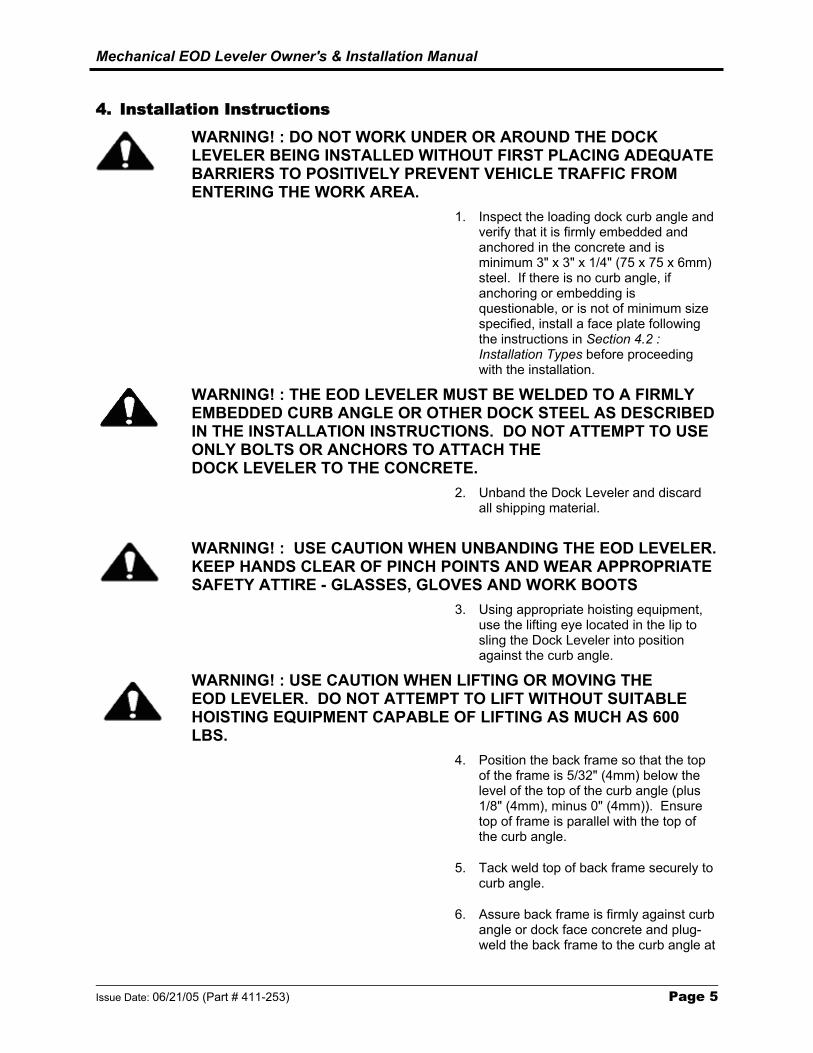
WARNING! : DO NOT WORK UNDER OR AROUND THE DOCK LEVELER BEING INSTALLED WITHOUT FIRST PLACING ADEQUATE BARRIERS TO POSITIVELY PREVENT VEHICLE TRAFFIC FROM ENTERING THE WORK AREA.
1. Inspect the loading dock curb angle and verify that it is firmly embedded and anchored in the concrete and is minimum 3" x 3" x 1/4" (75 x 75 x 6mm) steel. If there is no curb angle, if anchoring or embedding is questionable, or is not of minimum size specified, install a face plate following the instructions in Section 4.2 : Installation Types before proceeding with the installation.
WARNING! : THE EOD LEVELER MUST BE WELDED TO A FIRMLY EMBEDDED CURB ANGLE OR OTHER DOCK STEEL AS DESCRIBED IN THE INSTALLATION INSTRUCTIONS. DO NOT ATTEMPT TO USE ONLY BOLTS OR ANCHORS TO ATTACH THE DOCK LEVELER TO THE CONCRETE.
2. Unband the Dock Leveler and discard all shipping material.
WARNING! : USE CAUTION WHEN UNBANDING THE EOD LEVELER. KEEP HANDS CLEAR OF PINCH POINTS AND WEAR APPROPRIATE SAFETY ATTIRE - GLASSES, GLOVES AND WORK BOOTS
3. Using appropriate hoisting equipment, use the lifting eye located in the lip to sling the Dock Leveler into position against the curb angle.
WARNING! : USE CAUTION WHEN LIFTING OR MOVING THE EOD LEVELER. DO NOT ATTEMPT TO LIFT WITHOUT SUITABLE HOISTING EQUIPMENT CAPABLE OF LIFTING AS MUCH AS 600 LBS.
4. Position the back frame so that the top of the frame is 5/32" (4mm) below the level of the top of the curb angle (plus 1/8" (4mm), minus 0" (4mm)). Ensure top of frame is parallel with the top of the curb angle.
5. Tack weld top of back frame securely to curb angle.
6. Assure back frame is firmly against curb angle or dock face concrete and plug-weld the back frame to the curb angle at

Mechanical EOD Leveler Owner's & Installation Manual
Page 6 Issue Date: 06/21/05 (Part # 411-253)
the four circular holes in the frame. If curb angle does not overlap these holes, use the back plate as a template and drill four holes 5/8" dia. x 6" (15mm x 150mm) deep, in the dock face concrete. Clean out holes and insert and permanently install appropriate concrete wedge anchors. (See Figure 1). Tighten enough to secure the Back Frame.
7. Finish weld the top of the back frame to the curb angle. Weld 1/4" x 5" (6mm x 125mm) long welds on both ends of the back frame. Repeat the 1/4" welds adjacent to and centered with the hinge spools (approx. 5" long) across the full width of the back frame.
8. Vertical weld both ends of back frame to curb angle, full length of vertical contact. Tighten Lag bolts at this time securely.
9. Position the left-hand bumper bracket (as viewed when standing on the driveway in front of the Dock Leveler) so that there is 1/2" (13mm) clearance between the bracket side and the control handle pocket, and the bracket is level with the top of the curb angle. Weld all horizontal and vertical contact areas between bracket and curb angle and plug weld mounting holes that overlap curb angle. Install concrete wedge anchors 5/8" x 6" (15mm x 150mm) in mounting holes that are not welded.
10. Position the right-hand bumper bracket so that there is a 1/2" (13mm) clearance between the bracket and the dock leveler deck plate. Weld all horizontal and vertical contact areas between bracket and curb angle and plug weld mounting holes that overlap curb angle. Install concrete wedge anchors 5/8" x 6" (15mm x 150mm) in mounting holes that are not welded.
11. Install the control handle in the pocket on the left side of the deck. To do so, remove the bolt from the bottom of the handle, insert handle through pocket, then re-install bolt through hole in handle.
12. Lubricate all pivot points using SAE30 motor oil or equivalent.
Mechanical EOD Leveler Owner's & Installation Manual
Issue Date: 06/21/05 (Part # 411-253) Page 7
4.1 Final Inspection
1. Clean up the entire work area and apply touch-
up paint to all welds, scratches and burns.
2. Ensure all concrete wedge anchors have been securely tightened and / or locked.
WARNING ! :READ AND UNDERSTAND THIS ENTIRE MANUAL PRIOR TO OPERATING.
3. Test operate the unit through several full cycles
of operation. Refer to Section 14 : Operating Procedures. If problems are noted, See Section 16 : Troubleshooting.
4. Leave these Instructions with the Dock Leveler
for use by owner.
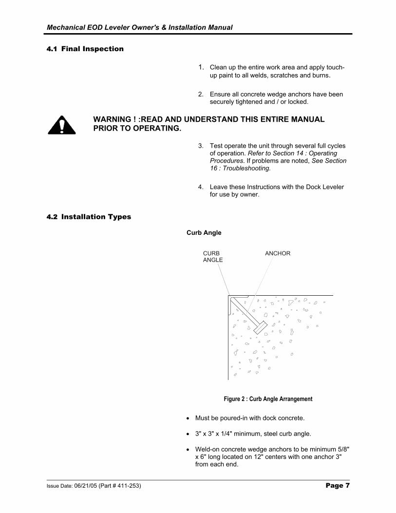
4.2 Installation Types Curb Angle
CURBANGLE
ANCHOR
Figure 2 : Curb Angle Arrangement
• Must be poured-in with dock concrete.
• 3" x 3" x 1/4" minimum, steel curb angle.
• Weld-on concrete wedge anchors to be minimum 5/8" x 6" long located on 12" centers with one anchor 3" from each end.

Mechanical EOD Leveler Owner's & Installation Manual
Page 8 Issue Date: 06/21/05 (Part # 411-253)
Optional Approach Ramp Installation
RAMP BUTTON HEADBOLT
WELD
CURBANGLE
ANCHOR
EXPANSIONSLEEVE
Figure 3 : Approach Ramp Arrangement
• Position ramp as illustrated. Outside edge of ramp flush with outside edge of curb angle.
• Tack-weld ramp to curb angle.
• Drill 3/4" dia. holes using ramp as a template. Insert 5/8" expansion sleeves (010-116). Install and tighten 5/8" x 1-1/2" button-head bolts (010-117) using 3/8" Allen key wrench
• Weld the ramp to the curb angle as illustrated. 1/4" x 5" welds on 9" centers.
Note : All hardware must be purchased separately as part of an optional mounting kit. Consult your local distributor/dealer for more information.

Mechanical EOD Leveler Owner's & Installation Manual
Issue Date: 06/21/05 (Part # 411-253) Page 9
Face Plate Types - For use on existing docks with no curb steel
One Piece Angle Plate
BEVELEDEDGE
Figure 4 : One Piece Angle Plate Arrangement
• 1/4" minimum plate thickness. Top plate 13" wide, face plate 10-" wide. Length to suit EOD Leveler model.
• Place angle plate on existing dock as shown. Use as drill template.
• Lag to sound concrete as follows:
Top Plate - Drill 3/4" dia. x 3-1/2" deep holes. Insert 5/8" expansion sleeves (010-116). Install and tighten 5/8" x 1-1/2" button-head bolts (010-117) using 3/8" Allen key. Face Plate - Drill 5/8" dia x 6" deep holes. Insert 5/8" x 6" long concrete anchor wedges (010-108) and tighten.
Note : All hardware must be purchased separately as part of an optional mounting kit. Consult your local distributor/dealer for more information.

Mechanical EOD Leveler Owner's & Installation Manual
Page 10 Issue Date: 06/21/05 (Part # 411-253)
Two Piece Angle Plate (Welded together on Site)
BEVELEDEDGEWELD
Figure 5 : One Piece Angle Plate Arrangement
• 1/4" minimum plate thickness. Top plate 13" wide, face plate 10" wide. Length to suite EOD Leveler model.
• Place top plate on top of existing dock, front edge flush with dock face, full length.
• Drill 3/4" dia. x 3-1/2" deep holes using plate as template. Insert 5/8" expansion sleeves (010-116). Install and tighten 5/8" x 1-1/2" button-head bolts (010-117) using 3/8" Allen key wrench.
• Place face plate in position as shown. Position top edge for welding and tack-weld to top plate.
• Drill 5/8" dia. x 6" deep holes using plate as a template. Insert 5/8" x 6" long concrete wedge anchors (010-108) and tighten.
• Weld the two plates together as illustrated. 1/4" x 5" long welds on 9" centers.
Note : All hardware must be purchased separately as part of an optional mounting kit. Consult your local distributor/dealer for more information.

Mechanical EOD Leveler Owner's & Installation Manual
Issue Date: 06/21/05 (Part # 411-253) Page 11
5. Routine Servicing And Maintenance
Regular maintenance and care of the Dock Leveler is very important for cost and operation efficiency and more importantly; operator safety. A faulty Dock Leveler is a potential source of danger to the operator, and to other personnel working near it. As with all quality equipment, keep the Dock Leveler in good operating condition by following the recommended schedule of maintenance. Failure to do so could also void the manufacturer's warranty.
Complete the Warranty Validation Form provided with this manual and return it to factory.
6. Component Identification
EXTENSION SPRINGS
EXTENSION ARMS
BACK FRAME
KICKERBAR
DECKHINGE
DECKLIPHINGE
LIPPLATE
CONTROLHANDLE
LIFTINGEYE
ADJUSTMENTSCREW
CONTROLHANDLEPOCKET
BUMPEREXTENSION
BUMPEREXTENSION
Figure 6 : Mechanical Edge-Of-Dock Leveler - Component Identification
Mechanical EOD Leveler Owner's & Installation Manual
Page 12 Issue Date: 06/21/05 (Part # 411-253)
7. Operator Daily Inspection
Safety and Operating Checks Dock Leveler should always be examined by the operator, before any use; to be sure it is safe to operate. The importance of this procedure is emphasized in this manual with a brief illustrated review and later with more detailed instructions. The manufacturer recommends making multiple photocopies of Section 12.3 : Operator's Daily Checklist. The operator should make a daily inspection prior to use; filling out this form in order to keep a daily record of operation and maintenance issues.
8. Planned Maintenance
In addition to the daily operator inspection, the manufacturer recommends and local Government regulations may require that a planned maintenance (PM) and safety inspection program be performed by a trained and authorized service technician on a regular basis to maintain the equipment in safe operating condition. The PM will provide an opportunity to make a thorough inspection of the safety and operating condition of the Dock Leveler. Necessary adjustments and repairs can be done during the PM, which will increase the life of components and reduce unscheduled downtime and increase safety. The PM can be scheduled to meet any particular application and Dock Leveler usage. The procedures for a periodic planned maintenance program that covers inspections, operational checks, cleaning, lubrication, and minor adjustments are outlined in this manual. An authorized dealer or distributor is prepared to assist with a Planned Maintenance Program by trained service personnel who possess expertise in Dock Leveler safety and efficiency. Lubrication : All pivot points and deck hinges should be lubricated every three months (for single shift operation) with SAE 30 engine oil. Refer to Figure 7 in Section 9.1 : Maintenance Sequence.
Mechanical EOD Leveler Owner's & Installation Manual
Issue Date: 06/21/05 (Part # 411-253) Page 13
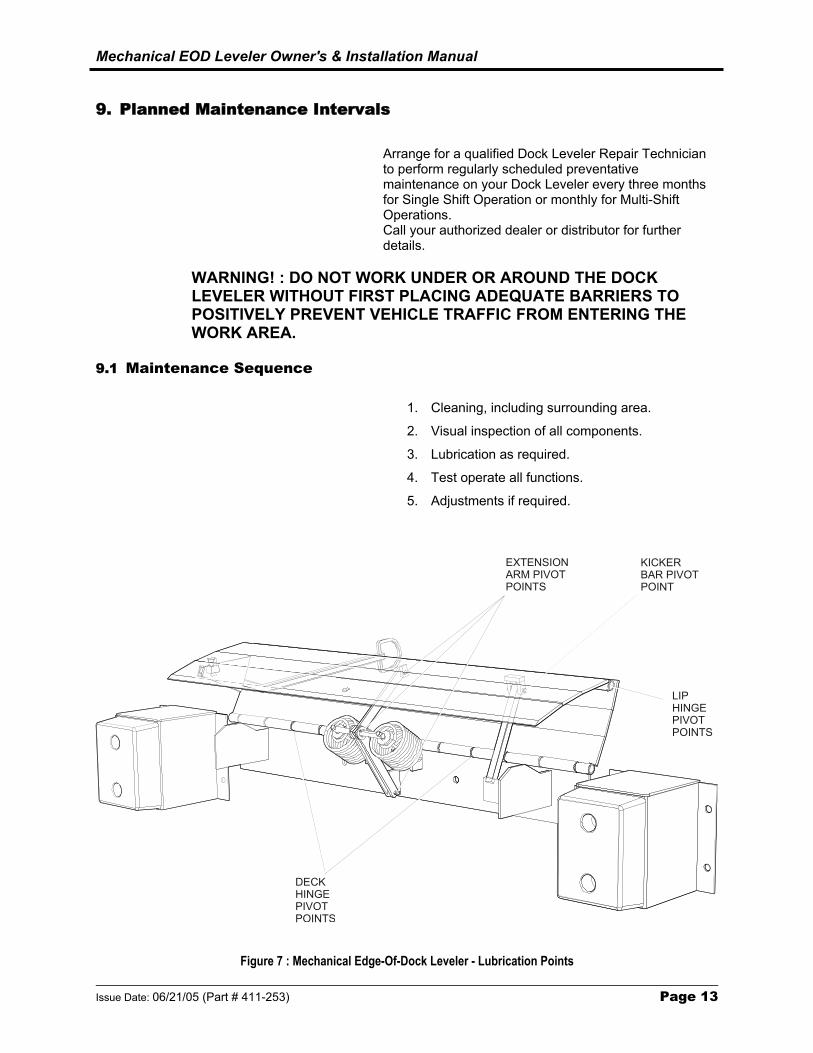
9. Planned Maintenance Intervals
Arrange for a qualified Dock Leveler Repair Technician to perform regularly scheduled preventative maintenance on your Dock Leveler every three months for Single Shift Operation or monthly for Multi-Shift Operations. Call your authorized dealer or distributor for further details.
WARNING! : DO NOT WORK UNDER OR AROUND THE DOCK LEVELER WITHOUT FIRST PLACING ADEQUATE BARRIERS TO POSITIVELY PREVENT VEHICLE TRAFFIC FROM ENTERING THE WORK AREA.
9.1 Maintenance Sequence
1. Cleaning, including surrounding area.
2. Visual inspection of all components.
3. Lubrication as required.
4. Test operate all functions.
5. Adjustments if required.
KICKERBAR PIVOTPOINT
EXTENSIONARM PIVOTPOINTS
LIPHINGEPIVOTPOINTS
DECKHINGEPIVOTPOINTS
Figure 7 : Mechanical Edge-Of-Dock Leveler - Lubrication Points

Mechanical EOD Leveler Owner's & Installation Manual
Page 14 Issue Date: 06/21/05 (Part # 411-253)
10. Safety Information
10.1 General
Dock Leveler are specialized equipment with unique operating characteristics, designed to perform a specific job. Their function and operation is not like any other piece of equipment. They require specific instructions and rules for safe operation and maintenance. In general, dock equipment accidents that result in injury or death can be the result of:
• Operator not properly trained
• Operator not experienced with Dock Leveler operation
• Basic safety rules not followed
• Dock Leveler not maintained in safe operating condition
This manual is designed to assist the operator become knowledgeable with respect to Dock Leveler safety. This manual illustrates and instructs the operator about safety inspections and the important general safety rules and hazards of Dock Leveler operation. It describes the special components and features of the Dock Leveler and explains their functions. The correct operating procedures are shown and explained. Illustrations and important safety messages are included for clear understanding.
The operator’s manual is not a training manual. It is a guide to help trained and authorized operators safely operate their Dock Leveler by emphasizing and illustrating the correct procedures. However, it cannot cover every possible situation that may result in an accident. Watch for hazards in all work areas and avoid or correct them. Do not allow potentially hazardous situations to go ignored or uncorrected. Read and understand all the information in this manual. Be aware of and obey all company safety rules! Be sure that all equipment is maintained in a safe condition. Do not operate a damaged or malfunctioning Dock Leveler. Practice safe operation every time the Dock Leveler is used.
This manual is intended to be readily available. Keep it near the Dock Leveler as a ready reference for anyone who may operate or service it. If the Dock Leveler being operated is not equipped with a manual, request to obtain one and have it located near the Dock Leveler. An authorized dealer or distributor is readily available to answer questions about Dock

Mechanical EOD Leveler Owner's & Installation Manual
Issue Date: 06/21/05 (Part # 411-253) Page 15
Leveler operation and maintenance and will provide additional information should it be required.
10.2 Safety Signs And Safety Messages
Improper operation can cause accidents. Don’t take chances with incorrect or damaged equipment. Read and understand the procedures for safe operation and maintenance outlined in this manual. Don’t hesitate to ask for help. Stay alert! Follow safety rules, regulations, and procedures. Avoid accidents by recognizing dangerous procedures or situations before they occur.
Safety signs and messages are placed in this manual to provide instructions and identify specific areas where potential hazards exist and special precautions should be taken. Know and understand the meaning of these instructions, signs, and messages. Damage to the Dock Leveler, death, or serious injury may result if these messages are not followed. If warning decals are damaged, they must be replaced. Contact an authorized dealer or distributor for replacements.
Place Safety Placard on wall near dock in clear view of operator.
NOTE : This message is used when special information, instructions or identification are required relating to procedures, equipment, tools, capacities and other special data.
IMPORTANT! : This message is used when special precautions should be taken to ensure a correct action or to avoid damage to or malfunction of the Dock Leveler or a component.
CAUTION! : This message indicates a potentially hazardous situation which, if not avoided, may result in minor or moderate injury
WARNING! : THIS MESSAGE INDICATES A POTENTIALLY HAZARDOUS SITUATION WHICH, IF NOT AVOIDED, COULD RESULT IN DEATH OR SERIOUS INJURY.
DANGER! : THIS MESSAGE INDICATES AN IMMINENTLY HAZARDOUS SITUATION WHICH, IF NOT AVOIDED, WILL RESULT IN DEATH OR SERIOUS INJURY.

Mechanical EOD Leveler Owner's & Installation Manual
Page 16 Issue Date: 06/21/05 (Part # 411-253)
10.3 General Safety Rules
• Be familiar with the Operating Principles of the Mechanical Edge-Of-Dock Leveler before attempting to operate it. Refer to Section 15 : Operating Procedures,.
• Do not exceed the Rated Capacity of the Dock Leveler as stated on the identification plate located on the right front side.
1. Dock Leveler model number or registered name.
2. The Dock Leveler serial number – An identification number assigned to this particular Dock Leveler and should be used when requesting information or ordering service parts for this Dock Leveler from an authorized dealer or distributor.
3. The Dock Leveler Capacity Rating – Do not overload the dock leveler.
• Do not allow untrained personnel to operate the Dock Leveler.
• Read this entire manual before attempting to operate the Dock Leveler.

Mechanical EOD Leveler Owner's & Installation Manual
Issue Date: 06/21/05 (Part # 411-253) Page 17
10.4 Safety Procedures
1. Always keep the work area clean and free of litter.
2. Always clean away all dirt and debris from the lip hinge,
3. Always clean up dry and liquid spills immediately when they occur.
4. Always maintain proper lighting in the work area.
5. Never leave the Dock Leveler unattended in the deployed position.
6. Never leave loads sitting on the Dock Leveler.
7. Never attempt to raise the Dock Leveler if someone is standing on it.
8. Never operate a broken or damaged Dock Leveler. Insist on immediate repairs by a qualified service technician.
9. Never attempt to perform repairs. Always defer even the smallest repairs to a qualified service technician.
10. Never try to lift or move any part of the Dock Leveler without using the Control Handle.
11. Never allow the use of the Dock Leveler if the transporter vehicle is not secured by a restraint device or wheel chocks.
12. Never allow use of the Dock Leveler if the full width of the lip is not in full contact with and fully supported by a transporter vehicle load bed.
13. Always secure and center loads on the lift truck forks. Loose or unbalanced loads are dangerous.
14. Always be aware of overhead clearance. Know the height of the lift truck, with and without a load. Check the clearance when crossing the dock leveler.
15. Always keep the lift truck load low and tilted back.

Mechanical EOD Leveler Owner's & Installation Manual
Page 18 Issue Date: 06/21/05 (Part # 411-253)
11. The Mechanical Edge of Dock Leveler - Functional Description
• The Mechanical Edge-of-Dock (EOD) Leveler is intended to be used as a bridge located between a loading dock floor surface and the rear deck upper surface of a Transporter Vehicle.
• The EOD Leveler upper deck plate complete with a hinged, vertically hanging lip plate is located flush with the floor surface and is permanently mounted on the outer edge of the loading dock.
• The rear deck surface of a Transporter Vehicle is parked and blocked in place against the dock bumpers that are integral components of the EOD Leveler, in working alignment with the EOD Leveler. An EOD Leveler used in conjunction with a Truck Restraint are ideal for this application. Consult your local Dealer/Distributor.
• The EOD Leveler is operated by pulling back on the control handle. The hinged lip plate raises to a horizontal position as the deck is rotated up into a vertical position. As the operator pushes the control handle forward, rotating the deck forward into a horizontal position, the lip moves forward horizontally until the underside comes to rest on the deck of the vehicle.
• A bridge is now formed that is supported at the building end by the dock floor and at the vehicle end by the vehicle deck.
• No other means of support is provided when in this position.
• The EOD Leveler is restored to its original stored position by the operator before the vehicle is allowed to depart.
Refer to Section 6 : Component Identification for illustration of EOD Leveler Components. Refer to Section 15 : Operating Procedures - Pictorials for detailed operating sequence.

Mechanical EOD Leveler Owner's & Installation Manual
Issue Date: 06/21/05 (Part # 411-253) Page 19
12. Operator Maintenance And Care
12.1 Daily Safety Inspection
Before using a EOD Leveler, it is the operator’s responsibility to check its condition and be sure it is safe to operate. Check for damage and maintenance problems; have repairs made before the EOD Leveler is operated. Unusual noises or problems must be reported immediately to a supervisor or other designated authority. Never attempt to perform repairs. Always defer even the smallest repairs to a qualified service technician. Have a qualified Dock Leveler Service Technician make repairs using parts approved by the manufacturer. Do not operate a EOD Leveler if it is in need of repair. If it is in unsafe condition, do not commence operation and report the condition to the proper authority. If the EOD Leveler becomes unsafe during operations, stop operating the EOD Leveler, report the problem immediately, and have it corrected. EOD Levelers should be inspected every day, at the start and end of each shift. In general, the daily inspection should include the visual and functional checks described on the following pages. As an aid in carrying out this inspection the manufacturer has prepared a form for reproduction and daily use. Refer to Section 12.3 : Operators Daily Checklist. The manufacturer recommends that this form be used to make a daily record of inspection and EOD Leveler condition.
12.2 Visual Checks
First, perform a visual inspection of the EOD Leveler and its major components:
1. Inspect the EOD Leveler from all possible viewpoints. Take note of obvious damage that may have been caused by operation during the last shift.
2. Check that all capacity, safety, and warning plates or decals are attached and legible.
3. Inspect for damaged or missing parts, rust, corrosion, bent parts, cracks, etc.
4. Carefully inspect the hinge points for cracks, breaks, bending, twists, and wear.

Mechanical EOD Leveler Owner's & Installation Manual
Page 20 Issue Date: 06/21/05 (Part # 411-253)
Visually inspect the EOD Leveler for signs of structural damage or mechanical malfunction as it is operated throughout the day. Be alert to abnormal sounds or operation and visually observe the condition of all components.
DANGER! : DO NOT ENTER THE AREA IN FRONT OF OR BELOW THE DOCK LEVELER. SERIOUS PERSONAL INJURY AND/OR DEATH MAY RESULT.
With the EOD Leveler in its stowed position, clean away wood splinters, nails, and other debris from the upper hinge surface.
WARNING! THE UPPER HINGE POINT IS A HAZARDOUS PINCH POINT. DO NOT USE FINGERS OR HANDS TO REMOVE FOREIGN MATERIALS. USE APPROPRIATE TOOLS.
Clean up spills and debris from the dock area floor and the EOD Leveler deck immediately when they are observed. If all the Daily Inspection checks are normal or satisfactory, the EOD Leveler can be operated. Make a record on Section 12.3 : Operator’s Daily Checklist of all problems that are detected. Review the checklist to be sure it has been completed and turn it in to the person responsible for Dock Leveler Maintenance. Be sure any unusual noises or problems are investigated immediately. Do not operate a Dock Leveler that has a maintenance problem or is not safe to operate.

Mechanical EOD Leveler Owner's & Installation Manual
Issue Date: 06/21/05 (Part # 411-253) Page 21
12.3 Operator's Daily Check List INSTRUCTIONS FOR USE: Indicate “OK for Use” with a check mark in the appropriate box of each inspection point.
Inspect the EOD Leveler from all possible viewpoints and take note of obvious damage that may have been caused by operation during the last shift.
Check that all capacity, safety, identification plates, etc. are attached and legible.
Inspect for damaged or missing parts, rust, corrosion, bent parts, cracks, etc.
Carefully inspect the hinge points for cracks, breaks, bending, twists, and wear.
Inspect the operating lever for damage or sharp edges.
With the EOD Leveler in its stowed position, clean away wood splinters, nails and other debris from
the upper lip-hinge surface by sweeping with broom.
Check for missing or damaged dock bumpers mounted on the bumper extensions.
Clean up spills from the dock area floor and the EOD Leveler immediately when they are observed.
Visually inspect the Dock Leveler for signs of structural damage or mechanical malfunction as the Dock Leveler is operated throughout the day. Be alert to abnormal sounds or operation and visually observe the condition of all components. Explain faults briefly in the space provided below.
INSPECTED BY: DATE: Forward checklist to the person responsible for dock leveler maintenance.

Mechanical EOD Leveler Owner's & Installation Manual
Page 22 Issue Date: 06/21/05 (Part # 411-253)
12.4 Operating Hazards
• Do not operate the dock leveler without being trained to do so.
• Know and follow all of these warnings and instructions:
1. Stay clear of dock leveler when transporter
vehicle is entering or leaving area.
2. Do not use or move the dock leveler if anyone is under or in front.
3. Keep hands and feet clear of pinch points.

Mechanical EOD Leveler Owner's & Installation Manual
Issue Date: 06/21/05 (Part # 411-253) Page 23
4. Keep a safe distance from both side edges.
5. Chock or restrain all transporter vehicles.
6. Lip must overlap bed of transporter vehicle a
minimum of 4” (100mm).
7. Do not use dock leveler if transporter vehicle
exceeds service range of 5” (127mm) above or 5” (127mm) below dock.

Mechanical EOD Leveler Owner's & Installation Manual
Page 24 Issue Date: 06/21/05 (Part # 411-253)
8. Do not exceed the rated capacity as indicated
on name plate.
9. Do not leave equipment or material unattended
on dock leveler.
10. Do not use a broken or damaged dock leveler.

Mechanical EOD Leveler Owner's & Installation Manual
Issue Date: 06/21/05 (Part # 411-253) Page 25
13. Before Operating The Dock Leveler
Anyone who is required to operate a Dock Leveler must read and understand the information in this Owner’s Manual and must be trained and authorized before initial operation. The Owner’s Manual should be stored where it can be made readily available.
WARNING! : A DOCK LEVELER CAN BE A POTENTIAL THREAT TO PERSONS AND PROPERTY IF NOT USED PROPERLY. SAFE OPERATION IS THE RESPONSIBILITY OF THE OPERATOR.
13.1 Load Handling
Handle only loads that are within the EOD Leveler rated capacity as shown on the nameplate. This includes the weight of the fork truck and the weight of its load. Handle only stable or safely arranged loads. Take the time to correctly stack and band loose items. Center the load on the Lift Truck Forks.
13.2 Traveling With A Load
Travel with load or carriage as low as possible across the EOD Leveler deck. Never travel with the load or carriage raised (elevated) in a high position. Do not elevate the load until clear of the Dock Leveler. Use special care when handling and traveling with long, high, or wide loads-to avoid losing the load, striking bystanders or obstructions. Do not turn until clear of the Dock Leveler. Watch clearances around the Dock Leveler during travel. Look out for obstructions, especially overhead. The impact of moving in and out of the trailer may cause the trailer to creep forward or move. A Truck Restraint that is used properly will prevent this situation from occurring. The following is a list of other prevention measures:
• Apply trailer brakes.
• Use wheel chocks.
• Use other suitable trailer-to-dock locking system if available.

Mechanical EOD Leveler Owner's & Installation Manual
Page 26 Issue Date: 06/21/05 (Part # 411-253)
14. Operating Instructions – Typical
Refer to Section 11 : The Mechanical Edge of Dock Leveler - Functional Description.
Note : The following is intended as a brief overview of EOD Leveler Operation. Refer to Section 15 : Operating Procedures - Pictorials for complete procedures.
11. The transporter vehicle driver reverses the
vehicle into position firmly against the dock bumper extensions.
12. The dock operator ensures the transporter vehicle is blocked securely (using either a vehicle restraint or wheel chocks) to prevent forward creep or unexpected departure.
13. The operator lifts the control handle up to the fully extended, raised position.
14. The Dock Leveler is operated by pulling back on the control handle
15. The hinged lip plate raises to a horizontal position as the deck is rotated up into a vertical position.
16. When the deck reaches its maximum up-travel stop, the operator then rotates the deck forward into a horizontal position by pushing forward on the control handle.
17. The lip moves forward horizontally, as the deck rotates downward, until the underside comes to rest on the deck of the transporter vehicle.
18. The unit is now ready for traffic.
WARNING! : THE TRANSPORTER VEHICLE MUST BE SECURED BY A VEHICLE RESTRAINT OR WHEEL CHOCKS TO PREVENT ITS MOVEMENT BEFORE COMMENCING TRAFFIC ACROSS THE DOCK LEVELER. CONSULT YOUR LOCAL DEALER/DISTRIBUTOR.
19. When traffic across the dock leveler has ceased
the operator must return the EOD Leveler to its stored position.
20. The operator raises the deck, by pulling back on the control handle, only enough to release the lip from the surface of the transporter vehicle loadbed. When the lip weldment swings down to pendant position, the unit is allowed to return to stored position.

Mechanical EOD Leveler Owner's & Installation Manual
Issue Date: 06/21/05 (Part # 411-253) Page 27
21. The transporter vehicle is then allowed to depart
by removing wheel chocks or releasing the vehicle restraint.

Mechanical EOD Leveler Owner's & Installation Manual
Page 28 Issue Date: 06/21/05 (Part # 411-253)
15. Operating Procedures - Pictorials
DOCK IS AVAILABLE FOR USE
Note : The control handle is shown in its stored position.
1. The transporter vehicle driver reverses the
vehicle into position firmly against the dock bumper extensions.
BUMPEREXTENSIONS
TRANSPORTERVEHICLE
VEHICLE RESTRAINT
2. The dock operator ensures the transporter vehicle is blocked securely (using either a vehicle restraint or wheel chocks) to prevent forward creep or unexpected departure.

Mechanical EOD Leveler Owner's & Installation Manual
Issue Date: 06/21/05 (Part # 411-253) Page 29
CONTROLHANDLE
3. The operator lifts the control handle up to the fully extended, raised position.
WARNING! : DO NOT ATTEMPT TO OPERATE THE EOD LEVELER WITHOUT USING THE CONTROL HANDLE.
4. The operator pulls the control handle backwards fully to rotate the handle to its lower most position.
The deck plate is past a vertical position and the lip plate is near horizontal.
Mechanical EOD Leveler Owner's & Installation Manual
Page 30 Issue Date: 06/21/05 (Part # 411-253)
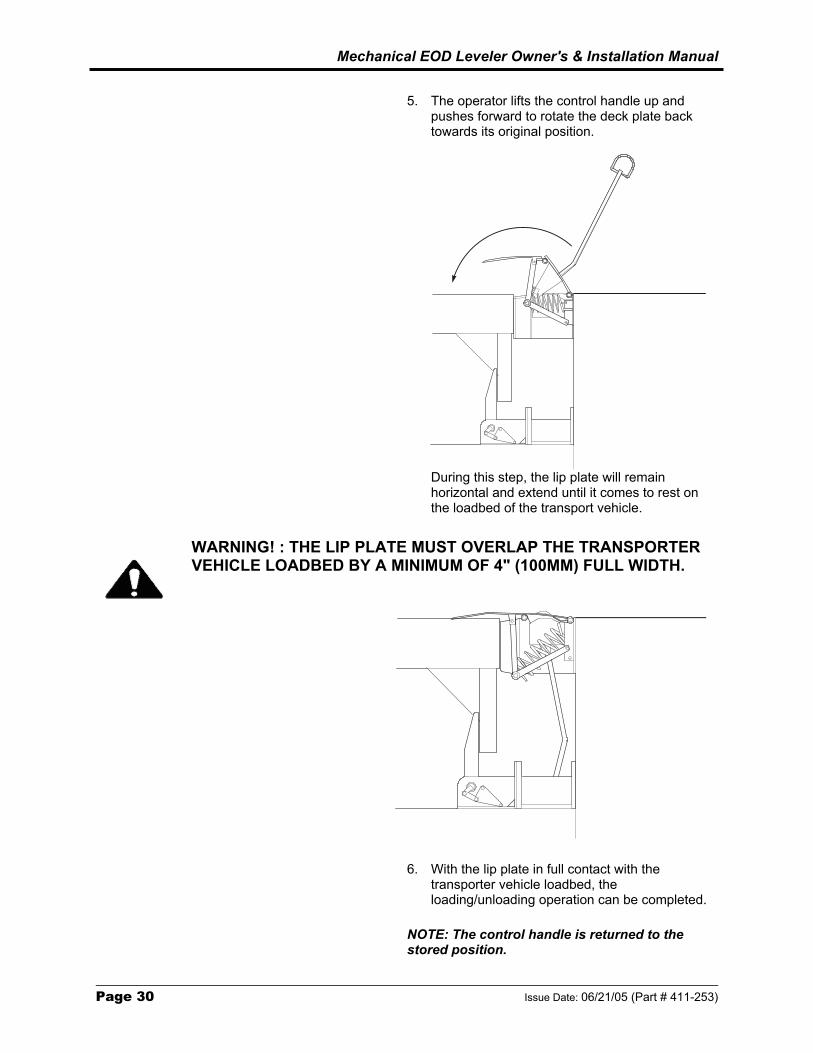
5. The operator lifts the control handle up and
pushes forward to rotate the deck plate back towards its original position.
During this step, the lip plate will remain horizontal and extend until it comes to rest on the loadbed of the transport vehicle.
WARNING! : THE LIP PLATE MUST OVERLAP THE TRANSPORTER VEHICLE LOADBED BY A MINIMUM OF 4" (100MM) FULL WIDTH.
6. With the lip plate in full contact with the transporter vehicle loadbed, the loading/unloading operation can be completed.
NOTE: The control handle is returned to the stored position.
Mechanical EOD Leveler Owner's & Installation Manual
Issue Date: 06/21/05 (Part # 411-253) Page 31
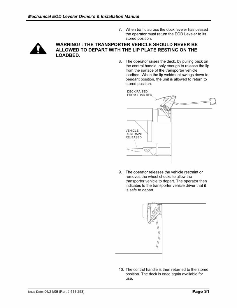
7. When traffic across the dock leveler has ceased
the operator must return the EOD Leveler to its stored position.
WARNING! : THE TRANSPORTER VEHICLE SHOULD NEVER BE ALLOWED TO DEPART WITH THE LIP PLATE RESTING ON THE LOADBED.
8. The operator raises the deck, by pulling back on the control handle, only enough to release the lip from the surface of the transporter vehicle loadbed. When the lip weldment swings down to pendant position, the unit is allowed to return to stored position.
VEHICLERESTRAINTRELEASED
DECK RAISEDFROM LOAD BED
9. The operator releases the vehicle restraint or removes the wheel chocks to allow the transporter vehicle to depart. The operator then indicates to the transporter vehicle driver that it is safe to depart.
10. The control handle is then returned to the stored position. The dock is once again available for use.
Mechanical EOD Leveler Owner's & Installation Manual
Page 32 Issue Date: 06/21/05 (Part # 411-253)
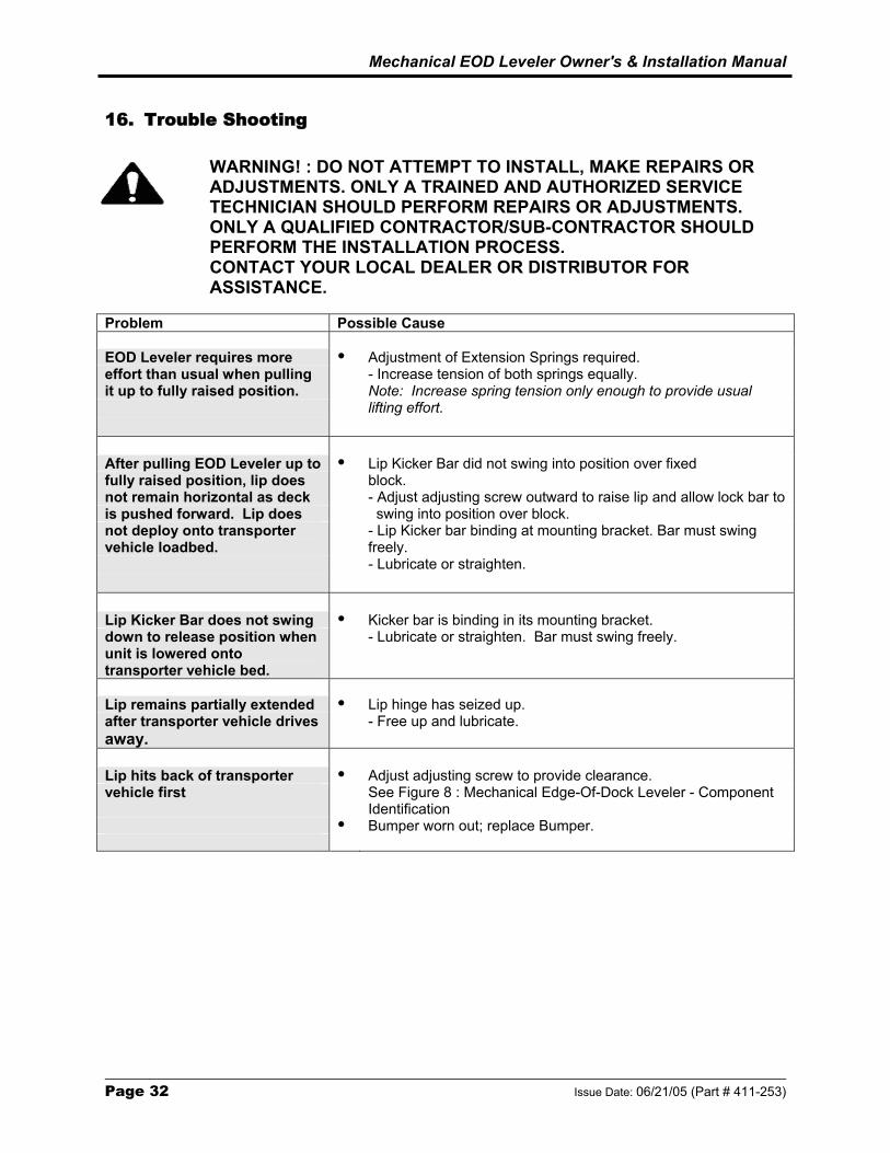
16. Trouble Shooting
WARNING! : DO NOT ATTEMPT TO INSTALL, MAKE REPAIRS OR ADJUSTMENTS. ONLY A TRAINED AND AUTHORIZED SERVICE TECHNICIAN SHOULD PERFORM REPAIRS OR ADJUSTMENTS. ONLY A QUALIFIED CONTRACTOR/SUB-CONTRACTOR SHOULD PERFORM THE INSTALLATION PROCESS. CONTACT YOUR LOCAL DEALER OR DISTRIBUTOR FOR ASSISTANCE.
Problem Possible Cause EOD Leveler requires more Adjustment of Extension Springs required. effort than usual when pulling - Increase tension of both springs equally. it up to fully raised position. Note: Increase spring tension only enough to provide usual lifting effort. After pulling EOD Leveler up to Lip Kicker Bar did not swing into position over fixed fully raised position, lip does block. not remain horizontal as deck - Adjust adjusting screw outward to raise lip and allow lock bar to is pushed forward. Lip does swing into position over block. not deploy onto transporter vehicle loadbed.
- Lip Kicker bar binding at mounting bracket. Bar must swing freely.
- Lubricate or straighten. Lip Kicker Bar does not swing Kicker bar is binding in its mounting bracket. down to release position when - Lubricate or straighten. Bar must swing freely. unit is lowered onto transporter vehicle bed.
Lip remains partially extended Lip hinge has seized up. after transporter vehicle drives - Free up and lubricate. away. Lip hits back of transporter Adjust adjusting screw to provide clearance. vehicle first See Figure 8 : Mechanical Edge-Of-Dock Leveler - Component
Identification Bumper worn out; replace Bumper.

Mechanical EOD Leveler Owner's & Installation Manual
Issue Date: 06/21/05 (Part # 411-253) Page 33
This page was intentionally left blank.
Mechanical EOD Leveler Owner's & Installation Manual
Page 34 Issue Date: 06/21/05 (Part # 411-253)
17. Mechanical EOD Leveler - Parts Listings 17.1 General Assembly - 20,000 lb. Capacity - 66,72&78" Wide
6
11
13
8712
119
11
5
8
13
712
1
2
252632
2526
24
329284
22
1423
2223
27
3031
15
21
16 1719
18
20
Figure 6 : General Assembly - 20,000 lb. Capacity - 66,72&78" Wide

Mechanical EOD Leveler Owner's & Installation Manual
Issue Date: 06/21/05 (Part # 411-253) Page 35
General Assembly - 20,000 lb. Capacity - 66,72&78" Wide
Item Qty Part No General Description Specific Description - - - Mechanical EOD Leveler Ref. Drwg. 250-5000 1 1 252-5001 Back Beam Weldment 66"-20K-15" Lip 1 1 252-5007 Back Beam Weldment 72"-20K-15" Lip 1 1 200-01527 Back Beam Weldment 78"-20K-15" Lip 2 1 252-5000 Deck Assy. 66"-20K-15" Lip 2 1 252-5006 Deck Assy. 72"-20K-15" Lip 2 1 200-01526 Deck Assy. 78"-20K-15" Lip 3 1 253-5000 Lip Assy. 66"-20K-15" Lip 3 1 253-5002 Lip Assy. 72"-20K-15" Lip 3 1 200-01525 Lip Assy. 78"-20K-15" Lip 4** 1 253-5001 Spring Shaft Assy. 66,72&78"-20K-15" Lip 5 1 252-0008 Spring Shaft - 3/4"Dia. X 9"Lg 66,72&78"-20K-15" Lip 6 3 253-0002 Extension Bar 66,72&78"-20K-15" Lip 7 2 010-083 Capscrew, Full Thrd. H.H. 3/8"-16x4" 66,72&78"-20K-15" Lip 8 2 011-507 Nut, Hex - 3/8"-16 66,72&78"-20K-15" Lip 9 4 012-298 Washer,Steel -2''ODx7/16''IDx3/16''TH 66,72&78"-20K-15" Lip 10 2 013-007 Spring Pin - 3/16"X1-1/4" 66,72&78"-20K-15" Lip 11 2 017-061 Spring, Extension 66,72&78"-20K-15" Lip 12 2 011-552 Nut, Hex 3/8"-16 Nylon Insert 66,72&78"-20K-15" Lip 13 2 012-245 Washer Spacer - 1"IDx1-3/4"ODx1/8"Thk 66,72&78"-20K-15" Lip 14 1 791-002 Handle Assy. 66,72&78"-20K-15" Lip 15** 2 791-013-1 Bumper Assy. 66"-20K-15" Lip 15** 2 791-013-1 Bumper Assy. 72"-20K-15" Lip 15** 2 791-013-1 Bumper Assy. 78"-20K-15" Lip 16 1 110-886 Bumper DB13 - 10"X13"X4" PROJ 66,72&78"-20K-15" Lip 17 2 010-086 Capscrew, Hex Hd. - 3/4"-10x3-1/4" 66,72&78"-20K-15" Lip 18 2 012-214 Washer, Fl. 3/4" Bolt Size 66,72&78"-20K-15" Lip 19 2 012-222 Lock Washer, 3/4" Split Reg. 66,72&78"-20K-15" Lip 20 2 011-510 Nut, Hex - 3/4"-10 66,72&78"-20K-15" Lip 21 1 242-5022 Bumper Bracket Weldment 66,72&78"-20K-15" Lip 21 1 252-5005 Bumper Bracket Extension 11" Ext. 66,72&78"-20K-15" Lip 22 2 300-170 Clevis Pin 66,72&78"-20K-15" Lip 23 2 013-006 Spring Pin 3/16 Dia. X 1" 66,72&78"-20K-15" Lip 24 1 200-01513 Lip Pin 66"-20K-15" Lip 24 1 200-01513-1 Lip Pin 72"-20K-15" Lip 24 1 200-01513-2 Lip Pin 78"-20K-15" Lip 25 4 010-072 H.H.C.S. 66,72&78"-20K-15" Lip 26 4 011-545 Hex. Nut 66,72&78"-20K-15" Lip 27 1 252-5002 Kicker Bar Weldment 66,72&78"-20K-15" Lip 28 1 250-0001 Kicker Bar Shaft 66,72&78"-20K-15" Lip 29 2 013-020 Cotter Pin 1/8 Dia. X 1" 66,72&78"-20K-15" Lip 30 1 010-059 Hex.H.C.S. 66,72&78"-20K-15" Lip 31 1 011-530 Hex. Nut 66,72&78"-20K-15" Lip 32 1 200-01513 Deck Pin 66"-20K-15" Lip 32 1 200-01513-1 Deck Pin 72"-20K-15" Lip 32 1 200-01513-2 Deck Pin 78"-20K-15" Lip * - INDENTED SUB-ASSEMBLY – SHOWN ON SAME PAGE ** - SUB-ASSEMBLY SHOWN ON SEPARATE PAGE

Mechanical EOD Leveler Owner's & Installation Manual
Page 36 Issue Date: 06/21/05 (Part # 411-253)
17.2 General Assembly - 25,000 lb. Capacity - 66,72&78" Wide
6
11
13
8712
119
11
5
8
13
712
1
2
252632
2526
24
329284
22
1423
2223
27
3031
15
21
16 1719
18
20
Figure 6 : General Assembly - 25,000 lb. Capacity - 66,72&78" Wide

Mechanical EOD Leveler Owner's & Installation Manual
Issue Date: 06/21/05 (Part # 411-253) Page 37
General Assembly - 25,000 lb. Capacity - 66,72&78" Wide
Item Qty Part No General Description Specific Description - - - Mechanical EOD Leveler Ref. Drwg. 200-01542 1 1 200-01517 Back Beam Weldment 66"-25K-15" Lip 1 1 200-01523 Back Beam Weldment 72"-25K-15" Lip 2 1 200-01514 Deck Assy. 66"-25K-15" Lip 2 1 200-01521 Deck Assy. 72"-25K-15" Lip 3 1 200-01515 Lip Assy. 66"-25K-15" Lip 3 1 253-01519 Lip Assy. 72"-25K-15" Lip 4* 1 253-5001 Spring Shaft Assy. 66&72"-25K-15 Lip 5 1 252-0008 Spring Shaft - 3/4"Dia. X 9"Lg 66&72"-25K-15" Lip 6 3 253-0002 Extension Bar 66&72"-25K-15" Lip 7 2 010-083 Capscrew, Full Thrd. H.H. 3/8"-16x4" 66&72"-25K-15" Lip 8 2 011-507 Nut, Hex - 3/8"-16 66&72"-25K-15" Lip 9 4 012-298 Washer, Steel - 2''ODx7/16''IDx3/16''TH 66&72"-25K-15" Lip 10 2 013-007 Spring Pin - 3/16"X1-1/4" 66&72"-25K-15" Lip 11 2 017-061 Spring, Extension 66&72"-25K-15" Lip 12 2 011-552 Nut, Hex 3/8"-16 Nylon Insert 66&72"-25K-15" Lip
13 2 012-245 Washer Spacer - 1"IDx1-3/4"ODx1/8"Thk 66&72"-25K-15" Lip
14 1 791-002 Handle Assy. 66&72"-25K-15" Lip 15* 2 791-013-1 Bumper Assy. 66"-25K-15" Lip 15* 2 791-013-1 Bumper Assy. 72"-25K-15" Lip 16 1 110-886 Bumper DB13 - 10"X13"X4" PROJ 66&72"-25K-15" Lip 17 2 010-086 Capscrew, Hex Hd. - 3/4"-10x3-1/4" 66&72"-25K-15" Lip 18 2 012-214 Washer, Fl. 3/4" Bolt Size 66&72"-25K-15" Lip 19 2 012-222 Lock Washer, 3/4" Split Reg. 66&72"-25K-15" Lip 20 2 011-510 Nut, Hex - 3/4"-10 66&72"-25K-15" Lip 21 1 242-5022 Bumper Bracket Weldment 66&72"-25K-15" Lip 21 1 252-5005 Bumper Bracket Extension 11" Ext. 66&72"-25K-15" Lip 22 2 300-170 Clevis Pin 66&72"-25K-15" Lip 23 2 013-006 Spring Pin 3/16 Dia. X 1" 66&72"-25K-15" Lip 24 1 300-172 Lip Pin 66"-25K-15" Lip 24 1 300-173 Lip Pin 72"-25K-15" Lip 25 4 010-000 H.H.C.S. 66&72"-25K-15" Lip 26 4 011-506 Hex. Nut 66&72"-25K-15" Lip 27 1 252-5002 Kicker Bar Weldment 66&72"-25K-15" Lip 28 1 250-0001 Kicker Bar Shaft 66&72"-25K-15" Lip 29 2 013-020 Cotter Pin 1/8 Dia. X 1" 66&72"-25K-15" Lip 30 1 010-059 Hex.H.C.S. 66&72"-25K-15" Lip 31 1 011-530 Hex. Nut 66&72"-25K-15" Lip 32 1 200-01513 Deck Pin 66"-25K-15" Lip 32 1 200-01513-1 Deck Pin 72"-25K-15" Lip * - INDENTED SUB-ASSEMBLY – SHOWN ON SAME PAGE ** - SUB-ASSEMBLY SHOWN ON SEPARATE PAGE

Mechanical EOD Leveler Owner's & Installation Manual
Page 38 Issue Date: 06/21/05 (Part # 411-253)
17.3 General Assembly - 30,000 lb. Capacity - 66&72" Wide
6
13
12
109
87
9
5
10
12
1
2
252632
2526
24
329284
22
1423
2223
27
3031
15
21
16 1719
18
20
Figure 6 : General Assembly - 30,000 lb. Capacity - 66&72" Wide

Mechanical EOD Leveler Owner's & Installation Manual
Issue Date: 06/21/05 (Part # 411-253) Page 39
General Assembly - 30,000 lb. Capacity - 66&72" Wide Item Qty Part No General Description Specific Description - - - Mechanical EOD Leveler Ref Drwg. 200-1541 1 1 200-01535 Back Beam Weldment 66"-30K-15" Lip 1 1 200-01536 Back Beam Weldment 72"-30K-15" Lip 2 1 200-01532 Deck Assy. 66"-30K-15" Lip 2 1 200-01533 Deck Assy. 72"-30K-15" Lip 3 1 200-01529 Lip Assy. 66"-30K-15" Lip 3 1 253-01530 Lip Assy. 72"-30K-15" Lip 4* 1 253-5001 Spring Shaft Assy. 66&72"-30K-15" Lip 5 1 252-0008 Spring Shaft - 3/4"Dia. X 9"Lg 66&72"-30K-15" Lip 6 3 253-0002 Extension Bar 66&72"-30K-15" Lip 7 2 010-083 Capscrew, Full Thrd. H.H. 3/8"-16x4" 66&72"-30K-15" Lip 8 2 011-507 Nut, Hex - 3/8"-16 66&72"-30K-15" Lip 9 4 012-298 Washer, Steel - 2''ODx7/16''IDx3/16''TH 66&72"-30K-15" Lip 10 2 013-007 Spring Pin - 3/16"X1-1/4" 66&72"-30K-15" Lip 11 2 017-061 Spring, Extension 66&72"-30K-15" Lip 12 2 011-552 Nut, Hex 3/8"-16 Nylon Insert 66&72"-30K-15" Lip 13 2 012-245 Washer Spacer - 1"IDx1-3/4"ODx1/8"Thk 66&72"-30K-15" Lip 14 1 791-002 Handle Assy. 66&72"-30K-15" Lip 15* 2 791-013-1 Bumper Assy. 66"-30K-15" Lip 15* 2 791-013-1 Bumper Assy. 72"-30K-15" Lip 16 1 110-886 Bumper DB13 - 10"X13"X4" PROJ 66&72"-30K-15" Lip 17 2 010-086 Capscrew, Hex Hd. - 3/4"-10x3-1/4" 66&72"-30K-15" Lip 18 2 012-214 Washer, Fl. 3/4" Bolt Size 66&72"-30K-15" Lip 19 2 012-222 Lock Washer, 3/4" Split Reg. 66&72"-30K-15" Lip 20 2 011-510 Nut, Hex - 3/4"-10 66&72"-30K-15" Lip 21 1 242-5022 Bumper Bracket Weldment 66&72"-30K-15" Lip 22 2 300-170 Clevis Pin 66&72"-30K-15" Lip 23 2 013-006 Spring Pin 3/16 Dia. X 1" 66&72"-30K-15" Lip 24 1 300-172 Lip Pin 66"-30K-15" Lip 24 1 300-173 Lip Pin 72"-30K-15" Lip 25 4 010-000 H.H.C.S. 66&72"-30K-15" Lip 26 4 011-506 Hex. Nut 66&72"-30K-15" Lip 27 1 252-5002 Kicker Bar Weldment 66&72"-30K-15" Lip 28 1 250-0001 Kicker Bar Shaft 66&72"-30K-15" Lip 29 2 013-020 Cotter Pin 1/8 Dia. X 1" 66&72"-30K-15" Lip 30 1 010-059 Hex.H.C.S. 66&72"-30K-15" Lip 31 1 011-530 Hex. Nut 66&72"-30K-15" Lip 32 1 200-01513 Deck Pin 66"-30K-15" Lip 32 1 200-01513-1 Deck Pin 72"-30K-15" Lip * - INDENTED SUB-ASSEMBLY – SHOWN ON SAME PAGE ** - SUB-ASSEMBLY SHOWN ON SEPARATE PAGE

Mechanical EOD Leveler Owner's & Installation Manual
Page 40 Issue Date: 06/21/05 (Part # 411-253)
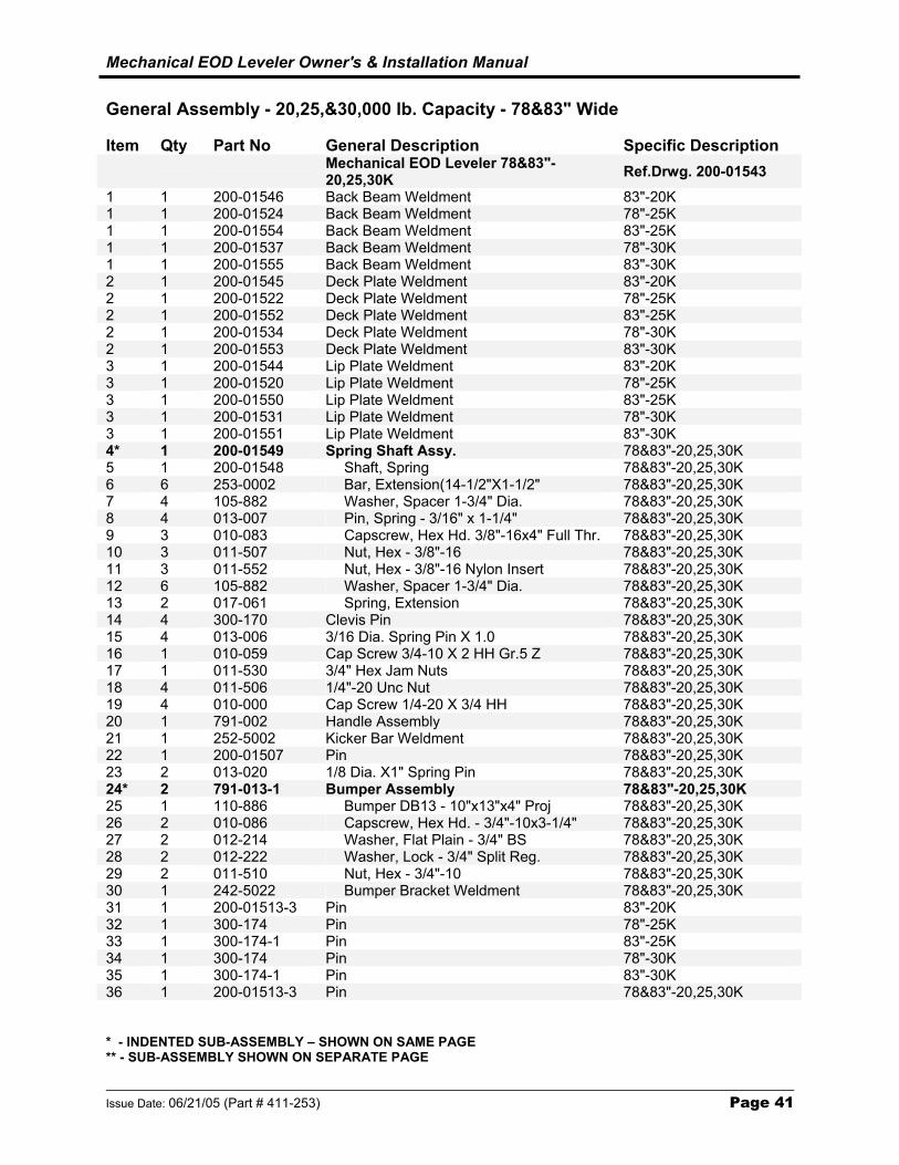
17.4 General Assembly - 20,25,&30,000 lb. Capacity - 78&83" Wide
1
2
321819191831
32322
4 1514151420
15 14
1514
21
1617
24
25 2628
27
29
30
6
13
12
109
87
98
7
5
9
10
12
Figure 6 : General Assembly - 78&83" - 20,25,30,000 lb. Capacity
Mechanical EOD Leveler Owner's & Installation Manual
Issue Date: 06/21/05 (Part # 411-253) Page 41
General Assembly - 20,25,&30,000 lb. Capacity - 78&83" Wide Item Qty Part No General Description Specific Description Mechanical EOD Leveler 78&83"-
20,25,30K Ref.Drwg. 200-01543 1 1 200-01546 Back Beam Weldment 83"-20K 1 1 200-01524 Back Beam Weldment 78"-25K 1 1 200-01554 Back Beam Weldment 83"-25K 1 1 200-01537 Back Beam Weldment 78"-30K 1 1 200-01555 Back Beam Weldment 83"-30K 2 1 200-01545 Deck Plate Weldment 83"-20K 2 1 200-01522 Deck Plate Weldment 78"-25K 2 1 200-01552 Deck Plate Weldment 83"-25K 2 1 200-01534 Deck Plate Weldment 78"-30K 2 1 200-01553 Deck Plate Weldment 83"-30K 3 1 200-01544 Lip Plate Weldment 83"-20K 3 1 200-01520 Lip Plate Weldment 78"-25K 3 1 200-01550 Lip Plate Weldment 83"-25K 3 1 200-01531 Lip Plate Weldment 78"-30K 3 1 200-01551 Lip Plate Weldment 83"-30K 4* 1 200-01549 Spring Shaft Assy. 78&83"-20,25,30K 5 1 200-01548 Shaft, Spring 78&83"-20,25,30K 6 6 253-0002 Bar, Extension(14-1/2"X1-1/2" 78&83"-20,25,30K 7 4 105-882 Washer, Spacer 1-3/4" Dia. 78&83"-20,25,30K 8 4 013-007 Pin, Spring - 3/16" x 1-1/4" 78&83"-20,25,30K 9 3 010-083 Capscrew, Hex Hd. 3/8"-16x4" Full Thr. 78&83"-20,25,30K 10 3 011-507 Nut, Hex - 3/8"-16 78&83"-20,25,30K 11 3 011-552 Nut, Hex - 3/8"-16 Nylon Insert 78&83"-20,25,30K 12 6 105-882 Washer, Spacer 1-3/4" Dia. 78&83"-20,25,30K 13 2 017-061 Spring, Extension 78&83"-20,25,30K 14 4 300-170 Clevis Pin 78&83"-20,25,30K 15 4 013-006 3/16 Dia. Spring Pin X 1.0 78&83"-20,25,30K 16 1 010-059 Cap Screw 3/4-10 X 2 HH Gr.5 Z 78&83"-20,25,30K 17 1 011-530 3/4" Hex Jam Nuts 78&83"-20,25,30K 18 4 011-506 1/4"-20 Unc Nut 78&83"-20,25,30K 19 4 010-000 Cap Screw 1/4-20 X 3/4 HH 78&83"-20,25,30K 20 1 791-002 Handle Assembly 78&83"-20,25,30K 21 1 252-5002 Kicker Bar Weldment 78&83"-20,25,30K 22 1 200-01507 Pin 78&83"-20,25,30K 23 2 013-020 1/8 Dia. X1" Spring Pin 78&83"-20,25,30K 24* 2 791-013-1 Bumper Assembly 78&83"-20,25,30K 25 1 110-886 Bumper DB13 - 10"x13"x4" Proj 78&83"-20,25,30K 26 2 010-086 Capscrew, Hex Hd. - 3/4"-10x3-1/4" 78&83"-20,25,30K 27 2 012-214 Washer, Flat Plain - 3/4" BS 78&83"-20,25,30K 28 2 012-222 Washer, Lock - 3/4" Split Reg. 78&83"-20,25,30K 29 2 011-510 Nut, Hex - 3/4"-10 78&83"-20,25,30K 30 1 242-5022 Bumper Bracket Weldment 78&83"-20,25,30K 31 1 200-01513-3 Pin 83"-20K 32 1 300-174 Pin 78"-25K 33 1 300-174-1 Pin 83"-25K 34 1 300-174 Pin 78"-30K 35 1 300-174-1 Pin 83"-30K 36 1 200-01513-3 Pin 78&83"-20,25,30K * - INDENTED SUB-ASSEMBLY – SHOWN ON SAME PAGE ** - SUB-ASSEMBLY SHOWN ON SEPARATE PAGE
Mechanical EOD Leveler Owner's & Installation Manual
Page 42 Issue Date: 06/21/05 (Part # 411-253)
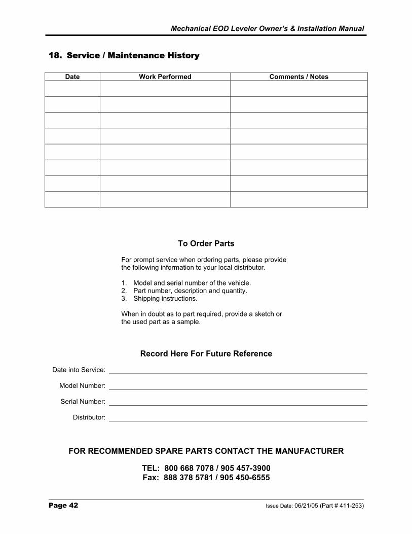
18. Service / Maintenance History
Date Work Performed Comments / Notes
To Order Parts
For prompt service when ordering parts, please provide the following information to your local distributor. 1. Model and serial number of the vehicle. 2. Part number, description and quantity. 3. Shipping instructions.
When in doubt as to part required, provide a sketch or the used part as a sample.
Record Here For Future Reference
Date into Service:
Model Number:
Serial Number:
Distributor:
FOR RECOMMENDED SPARE PARTS CONTACT THE MANUFACTURER
TEL: 800 668 7078 / 905 457-3900 Fax: 888 378 5781 / 905 450-6555
Mechanical EOD Leveler Owner's & Installation Manual
Issue Date: 06/21/05 (Part # 411-253) Page 43
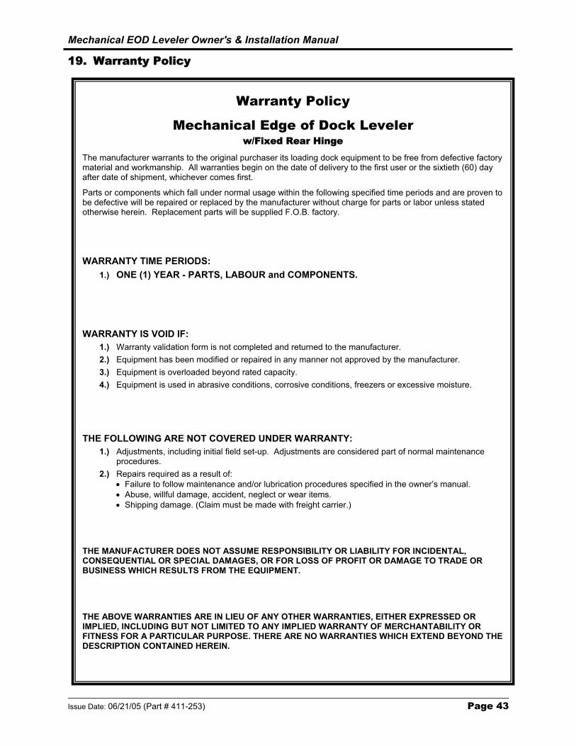
19. Warranty Policy
Warranty Policy
Mechanical Edge of Dock Leveler w/Fixed Rear Hinge
The manufacturer warrants to the original purchaser its loading dock equipment to be free from defective factory material and workmanship. All warranties begin on the date of delivery to the first user or the sixtieth (60) day after date of shipment, whichever comes first.
Parts or components which fall under normal usage within the following specified time periods and are proven to be defective will be repaired or replaced by the manufacturer without charge for parts or labor unless stated otherwise herein. Replacement parts will be supplied F.O.B. factory.
WARRANTY TIME PERIODS: 1.) ONE (1) YEAR - PARTS, LABOUR and COMPONENTS.
WARRANTY IS VOID IF: 1.) Warranty validation form is not completed and returned to the manufacturer. 2.) Equipment has been modified or repaired in any manner not approved by the manufacturer. 3.) Equipment is overloaded beyond rated capacity. 4.) Equipment is used in abrasive conditions, corrosive conditions, freezers or excessive moisture.
THE FOLLOWING ARE NOT COVERED UNDER WARRANTY: 1.) Adjustments, including initial field set-up. Adjustments are considered part of normal maintenance
procedures. 2.) Repairs required as a result of:
• Failure to follow maintenance and/or lubrication procedures specified in the owner’s manual. • Abuse, willful damage, accident, neglect or wear items. • Shipping damage. (Claim must be made with freight carrier.)
THE MANUFACTURER DOES NOT ASSUME RESPONSIBILITY OR LIABILITY FOR INCIDENTAL, CONSEQUENTIAL OR SPECIAL DAMAGES, OR FOR LOSS OF PROFIT OR DAMAGE TO TRADE OR BUSINESS WHICH RESULTS FROM THE EQUIPMENT.
THE ABOVE WARRANTIES ARE IN LIEU OF ANY OTHER WARRANTIES, EITHER EXPRESSED OR IMPLIED, INCLUDING BUT NOT LIMITED TO ANY IMPLIED WARRANTY OF MERCHANTABILITY OR FITNESS FOR A PARTICULAR PURPOSE. THERE ARE NO WARRANTIES WHICH EXTEND BEYOND THE DESCRIPTION CONTAINED HEREIN.


For Service Parts, Contact your Local Dealer/Distributor For Customer Service : Tel 800 668 7078 Fax 888 378 5781
B L U E G I A N T E Q U I P M E N T C O R P O R A T I O N
85 Heart Lake Road South,
Brampton, Ontario Canada L6W 3K2
Tel 800 668 7078 Fax 888 378 5781
www.BlueGiant.com
BLUE GIANT offers a full line of Dock Levelers, Dock Safety Equipment, Accessories, Ergonomic and Scissor Lift Equipment, and Industrial Trucks. Concurrent with our continuing product
improvement program, specifications are subject to change without notice. Please contact BLUE GIANT for latest information. Some features illustrated may be optional in certain market areas.
Warning: This manual may not be copied, quoted or transferred in any form or medium to any individual or company, in whole or in part without written consent from Blue Giant.
If calling from outside North America: Tel 905 457 3900 Fax 905 450 6555
Issue Date : 06/21/05 (Part # 411-253)