owner’s guide btf - cadet electric heating products · • follow the instructions in your...
TRANSCRIPT
http://cadetheat.com/install/btfFor how-to videos or more information, please visit:
ESPAÑOL ver la guía del propietario en cadetheat.com/espanol/btf
cadetheat.com 855.CADET.US Vancouver, Washington tested to UL standards
OWNER’S GUIDE
BTFBUILT-IN BASEBOARD THERMOSTAT
SAVE THESE INSTRUCTIONS
IMPORTANT INSTRUCTIONS2
WORKING WITH ELECTRICITY
REQUIRED TOOLS
1. Read all instructions before install-ing or using this thermostat.
2. Use this thermostat only as described in this manual. Any other use not recommended by the manufacturer may cause fire, electric shock, or injury to persons.
3. Do not insert or allow foreign ob-jects to enter any ventilation or ex-haust opening as this may cause an electric shock or fire, or damage the heater or thermostat.
4. To disconnect thermostat turn off power to heater circuit at main dis-connect panel.
5. Do not operate any thermostat after it malfunctions. Disconnect power at main disconnect panel and have thermostat inspected by a qualified electrician before reusing.
6. A thermostat has arcing or sparking parts inside. Do not use in areas where gasoline, paint, or flammable liquids are stored.
When using electrical appliances, basic precautions should always be followed to reduce the risk of fire, electric shock, and injury to persons, including the following:
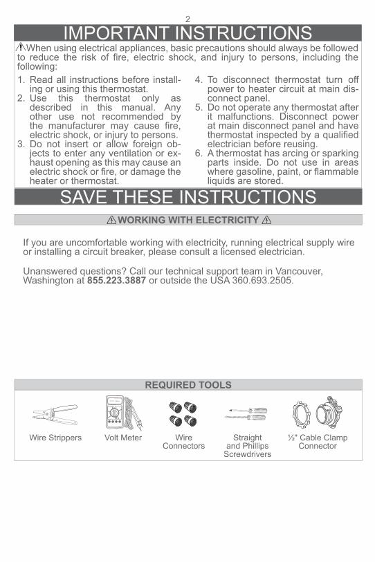
Straight and Phillips
Screwdrivers
Wire Strippers Wire Connectors
½" Cable Clamp Connector
Volt Meter
®
®
®
®
®
If you are uncomfortable working with electricity, running electrical supply wire or installing a circuit breaker, please consult a licensed electrician.
Unanswered questions? Call our technical support team in Vancouver, Washington at 855.223.3887 or outside the USA 360.693.2505.
®
INSTALLATION INSTRUCTIONS3
1. All electrical work and materials must comply with the National Elec-tric Code (NEC), the Occupational Safety and Health Act (OSHA), and all state and local codes.
2. Use copper conductors only.3. Use only on series F baseboard
heaters.
4. Turn off power to heater at main disconnect panel.
5. Connect grounding lead to grounding screw provided on the heater.
6. Use wire connectors (not included) for all connections.
• Verify power has been turned off before starting any work! • Follow the instructions in your Baseboard Owner’s Guide (included with your heater) until
prompted to make thermostat connections. • IMPORTANT: If wiring on the left side, cut ONLY ONE factory connection and ONLY on the
side you will be wiring! If your baseboard is a 120 volt model, cut ONLY the factory connec-tion that has one black and one white wire!
240/208 Volt LEFT SIDE
TIPS BEFORE YOU BEGIN
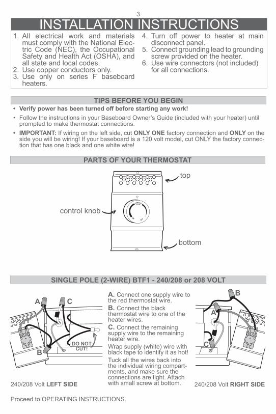
A. Connect one supply wire to the red thermostat wire. B. Connect the black thermostat wire to one of the heater wires. C. Connect the remaining supply wire to the remaining heater wire. Wrap supply (white) wire with black tape to identify it as hot! Tuck all the wires back into the individual wiring compart-ments, and make sure the connections are tight. Attach with small screw at bottom.
SINGLE POLE (2-WIRE) BTF1 - 240/208 or 208 VOLT
240/208 Volt RIGHT SIDE
PARTS OF YOUR THERMOSTAT
control knob
top
bottom
Proceed to OPERATING INSTRUCTIONS.
A
B
C
A
B
C
DO NOT CUT!

4
A. Connect the two black thermostat wires to the two loose heater wires. B. Connect the two hot supply wires to the two red thermostat wires. Wrap supply (white) wire with black tape to identify it as hot! Tuck all the wires back into the individual wiring com-partments, and make sure the connections are tight. Attach with small screw at bottom.
DOUBLE POLE (4-WIRE) BTF2 - 240/208 or 208 VOLT
120 Volt LEFT SIDE
120 Volt RIGHT SIDE
A. Connect the red thermostat wire labeled L2 to the black thermostat wire labeled OFF. B. Connect the neutral (white) supply wire to the white heater wire. C. Connect the hot supply wire to the remaining red thermostat wire. D. Connect the remaining black thermostat wire to the remain-ing heater wire. Tuck all the wires back into the individual wiring compartments, and make sure the connections are tight. Attach with small screw at bottom.
120 Volt RIGHT SIDE
240/208 Volt RIGHT SIDE
A. Connect the hot supply wire to the red thermostat wire. B. Connect the black thermo-stat wire to the black heater wire. C. Connect the neutral (white) supply wire to the white heater wire. Tuck all the wires back into the individual wiring compart-ments, and make sure the connections are tight. Attach with small screw at bottom.
240/208 Volt LEFT SIDE
120 Volt LEFT SIDE
INSTALLATION INSTRUCTIONSSINGLE POLE (2-WIRE) BTF1 - 120 VOLT
DOUBLE POLE (4-WIRE) BTF2 - 120 VOLT
Proceed to OPERATING INSTRUCTIONS.
Proceed to OPERATING INSTRUCTIONS.
Proceed to OPERATING INSTRUCTIONS.
A
B
C
A
AB B
A
B
C
D
A
B
A
B
AB
C
D
A
B
C
DO NOT CUT!
DO NOT CUT!
DO NOT CUT!
5
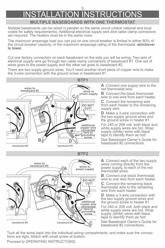
INSTALLATION INSTRUCTIONSMULTIPLE BASEBOARDS WITH ONE THERMOSTAT
Multiple baseboards can be wired in parallel on the same circuit (check national and local codes for safety requirements). Additional electrical supply wire and cable clamp connectors are required. The heaters must be in the same room.The maximum amperage load you can put on one circuit breaker is limited to either 80% of the circuit breaker capacity, or the maximum amperage rating of the thermostat, whichever is lower.
A. Connect one supply wire to the red thermostat wire. B. Connect the black thermostat wire to one wire from each heater. C. Connect the remaining wire from each heater to the remaining supply wire. D. Make a 3-wire connection with the two supply ground wires and the ground screw in heater #1. For 240 or 208 volt, both black and white supply wires are hot. Wrap supply (white) wires with black tape to identify them as hot! See Baseboard Owner’s Guide for baseboard #2 connections.
A. Connect each of the two supply wires coming directly from the power supply, to each of the red thermostat wires. B. Connect one black thermostat wire to one wire from each heater. C. Connect the remaining black thermostat wire to the remaining wire from each heater. D. Make a 3-wire connection with the two supply ground wires and the ground screw in heater #1. For 240 or 208 volt, both black and white supply wires are hot. Wrap supply (white) wires with black tape to identify them as hot! See Baseboard Owner’s Guide for baseboard #2 connections.
Cut one factory connection on each baseboard on the side you will be wiring. Two sets of electrical supply wire go through two cable clamp connectors of baseboard #1. One set of wires goes to the power supply and the other set goes to baseboard #2. There are two supply ground wires. You’ll need another short piece of copper wire to make the 3-wire connection with the ground screw in baseboard #1.
Tuck all the wires back into the individual wiring compartments, and make sure the connec-tions are tight. Attach with small screw at bottom. Proceed to OPERATING INSTRUCTIONS.
BTF1
BTF2
A
B
C
A
baseboard #1baseboard #2
wires to power supply
baseboard #1baseboard #2
wires to baseboard #2
DO NOT CUT!
A
B
C
D
D
DO NOT CUT!
wires to power supply
wires to baseboard #2
additional copper wire connected
here to grounding
screw
additional copper wire connected
here to grounding
screw
Rev 03/01/17 #720107
Reduce-Reuse-RecycleThis product is made primarily of recyclable materials. You can reduce your carbon footprint by recycling this product at the end of its useful life. Contact your local recycling support center for further recycling instructions.
WARRANTYFor more effective and safer operation and to prolong the life of the heater, read the Owner’s Guide and follow the instructions. Failure to properly maintain the heater will void any warranty and may cause the heater to function improperly. LIMITED ONE YEAR WARRANTY: Cadet will repair or replace any Cadet BTF thermostat found to be defective within one year after the date of purchase.These warranties do not apply:1. Damage occurs to the product through improper installation or incorrect supply voltage;2. Damage occurs to the product through improper maintenance, misuse, abuse, accident, or alteration;3. The use of unauthorized accessories or unauthorized components constitutes an alteration and voids all warranties. Refer to Cadet website or call customer service at 855.223.3887 or 360.693.2505 for list of authorized accessories and components. 4. CADET’S WARRANTY IS LIMITED TO REPAIR OR REPLACEMENT.
5. IN THE EVENT CADET ELECTS TO REPLACE ANY PART OF YOUR CADET PRODUCT, THE REPLACEMENT PARTS ARE SUBJECT TO THE SAME WARRANTIES AS THE PRODUCT. THE INSTALLATION OF REPLACEMENT PARTS DOES NOT MODIFY OR EXTEND THE UNDERLYING WARRANTIES. REPLACEMENT OR REPAIR OF ANY CADET PRODUCT OR PART DOES NOT CREATE ANY NEW WARRANTIES.If you believe your Cadet product is defective, please contact Cadet during the warranty period, for instructions on how to have the repair or replacement processed.Parts and ServiceVisit cadetheat.com/parts-service for information on where to obtain parts and service.
More frequently asked questions on our website here: cadetheat.com/support/FAQ
©2017 Cadet Printed in USA
To register your product, visit cadetheat.com/product-registration
6
Make sure all wires are properly connected and installation is complete before you turn on the heater.
OPERATING INSTRUCTIONS
Turn power back on at the main disconnect panel. 1. Turn the thermostat knob all the way to the right. For tamper proof models, remove small
plastic plug first, then turn the thermostat shaft all the way to the right.2. When the room reaches your comfort level, turn the knob/shaft to the left, just until it clicks
and the heater turns off. The heater will automatically keep the room temperature at this setting.
3. To reduce the room temperature, turn the knob to the left. To increase the room tempera-ture, turn the knob to the right.