owner’s manual and operating instructions
TRANSCRIPT

Model #SE45-R2
Owner’s Manual and Operating Instructions
4500 lb.UTV WINCH
Revision Date 2020-12-09


5 SE45-R2
Table of Contents
Introduction���������������������������������������������������������������������������������� 1 Accessories �������������������������������������������������������������������������������������������������������1 This Booklet �����������������������������������������������������������������������������������������������������1Introduction���������������������������������������������������������������������������������� 1Manual�Conventions�������������������������������������������������������������������� 3Safety�Rules����������������������������������������������������������������������������������� 4Controls�and�Features������������������������������������������������������������������ 5 Winch ���������������������������������������������������������������������������������������������������������������5Installation������������������������������������������������������������������������������������� 6 Step 1-Mount the Winch ����������������������������������������������������������������������������������6 Step 2-Mount the Contactor �����������������������������������������������������������������������������6 Step 3-UTV Dash Mounted Rocker Switch Kit ����������������������������������������������6 Step 4-Mount the Hand Remote Socket (Optional) �����������������������������������������7 Step 5-Wiring the Winch ����������������������������������������������������������������������������������7Winch�Wiring�Diagram���������������������������������������������������������������� 8Switch�Wiring�Diagram��������������������������������������������������������������� 9Cable�Hook�Stopper�Installation�and�Use���������������������������������� 9Operation������������������������������������������������������������������������������������� 10 General Tips for Safe Operation ���������������������������������������������������������������������10 Self Recovery �������������������������������������������������������������������������������������������������10 Winching Techniques ������������������������������������������������������������������������������������11Maintenance�������������������������������������������������������������������������������� 12 Lubrication �����������������������������������������������������������������������������������������������������12 Cable Assembly Replacement ������������������������������������������������������������������������12 SE45-R2�Specifications�������������������������������������������������������������� 13 Performance Specifications ����������������������������������������������������������������������������13 Model Winch Diagram �����������������������������������������������������������������������������������14 Winch Parts List ���������������������������������������������������������������������������������������������15Troubleshooting�������������������������������������������������������������������������� 16Plowing�Alert������������������������������������������������������������������������������� 16Warranty������������������������������������������������������������������������������������� 17 Warranty Qualifications ���������������������������������������������������������������������������������17 Repair/Replacement Warranty �����������������������������������������������������������������������17 Do not return the unit to the place of purchase ����������������������������������������������17 Warranty Exclusions ��������������������������������������������������������������������������������������17 Normal Wear �����������������������������������������������������������������������������������������������17 Installation, Use and Maintenance �����������������������������������������������������������������17 Other Exclusions ��������������������������������������������������������������������������������������������17 Limits of Implied Warranty and Consequential Damage �������������������������������17 Contact Information ����������������������������������������������������������������������������������������18 Address �����������������������������������������������������������������������������������������������������������18 Corporate: �������������������������������������������������������������������������������������������������������18 Customer Service ��������������������������������������������������������������������������������������������18 Technical Service �������������������������������������������������������������������������������������������18 Agreement ������������������������������������������������������������������������������������������������������18Synthetic�Cable��������������������������������������������������������������������������� 19


1SE45-R2
Introduction
IntroductionCongratulations on your purchase of a KFI winch. KFI researches and develops winches to strict specifications. With proper use and maintenance, this winch will bring years of satisfying service.
AccessoriesKappers Fabricating Inc. manufactures, purchases and sells accessories designed to help you get the most from your purchase. To find out more about our products visit our web site at
www.kfiproducts.com
Record the model as well as date and place of purchase for future reference. Have this information available when ordering parts and when making technical or warranty inquiries.
This BookletEvery effort has been made to ensure the accuracy and completeness of the information in this manual. We reserve the right to change, alter and/or improve the product and this document at any time without prior notice.
Kappers Fabricating Inc� Support
1-877-346-2050
Model Number
SE45-R2
Date of Purchase
Purchase Location
Serial Number

2 SE45-R2
CAUTION used without the safety alert symbol indicates a potentially hazardous situation which, if not avoided, may result in propertydamage.
CAUTION indicates a potentially hazardous situation which, if not avoided, may result in minor or moderate injury.
WARNING indicates a potentially hazardous situation which, if not avoided, could result in death or serious injury.
DANGER indicates an imminently hazardous situation which, if not avoided, will result in death or serious injury.
Manual ConventionsThis manual uses the following symbols to help differentiate between different kinds of information. The safety symbol is used with a key word to alert you to potential hazards in operating and owning a winch.
Follow all safety messages to avoid or reduce the risk of serious injury or death.
Manual Conventions
DANGER
NOTEIf you have questions regarding your winch, we can help. Please call our help line at 1-877-346-2050.
WARNING
CAUTION
CAUTION

3SE45-R2
Manual Conventions
Safety Rules
Do not use this winch for lifting or moving people or animals.
DANGER
Read this manual thoroughly before operating your winch. Failure to follow instructions could result in serious injury or death.
WARNINGDo not move the vehicle to pull a load (towing) on the winch cable. This could result in cable breakage.
WARNING
Pull only on areas of the vehicle as specified by the vehicle manufacturer
WARNING
Do not exceed the rated capacity.WARNING
Keep yourself and others a safe distance to the side of the cable when under tension.
WARNING
Never step over a cable or near a cable under load.
WARNING
The wire rope may break before the motor stalls. For heavy loads at or near rated capac-ity, use a pulley block/snatch block to reduce the load on the wire rope.
WARNING
Do not use the winch to secure or hold a vehicle for a long period of time. Do not use the winch to secure a vehicle for transport.
WARNING
Disconnect the remote control and battery leads when not in use for extended periods.
WARNING
Avoid “shock loads” by using the control switch intermittently to take up the slack in the wire rope. “Shock loads” can far exceed the rate capacity for the wire rope and drum.
Do not accelerate your vehicle while winching. Loss of traction can cause a shock load on the cable. Do not use cable as a pull strap.
WARNING
4 SE45-R2
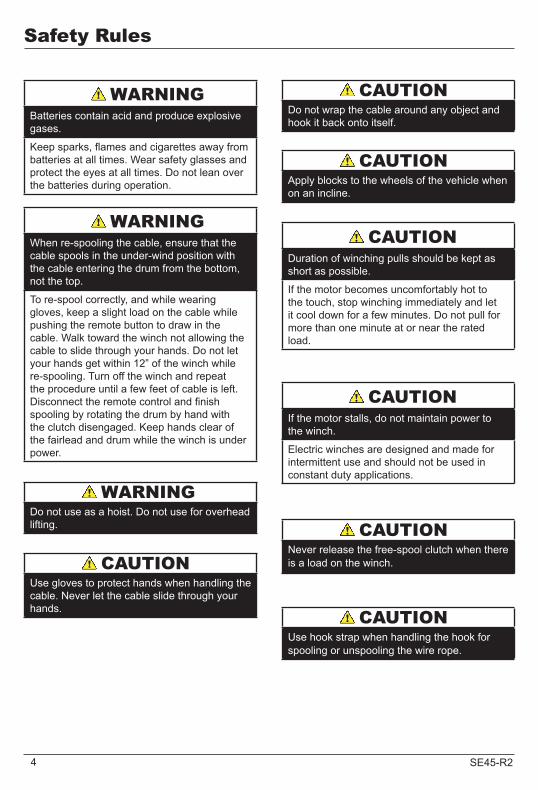
Do not use as a hoist. Do not use for overhead lifting.
Safety Rules
WARNING
Batteries contain acid and produce explosive gases.
Keep sparks, flames and cigarettes away from batteries at all times. Wear safety glasses and protect the eyes at all times. Do not lean over the batteries during operation.
WARNING
When re-spooling the cable, ensure that the cable spools in the under-wind position with the cable entering the drum from the bottom, not the top.
To re-spool correctly, and while wearing gloves, keep a slight load on the cable while pushing the remote button to draw in the cable. Walk toward the winch not allowing the cable to slide through your hands. Do not let your hands get within 12” of the winch while re-spooling. Turn off the winch and repeat the procedure until a few feet of cable is left. Disconnect the remote control and finish spooling by rotating the drum by hand with the clutch disengaged. Keep hands clear of the fairlead and drum while the winch is under power.
WARNING
Duration of winching pulls should be kept as short as possible.
If the motor becomes uncomfortably hot to the touch, stop winching immediately and let it cool down for a few minutes. Do not pull for more than one minute at or near the rated load.
CAUTION
Apply blocks to the wheels of the vehicle when on an incline.
CAUTION
Do not wrap the cable around any object and hook it back onto itself.
CAUTION
Use gloves to protect hands when handling the cable. Never let the cable slide through your hands.
CAUTION
If the motor stalls, do not maintain power to the winch.
Electric winches are designed and made for intermittent use and should not be used in constant duty applications.
CAUTION
Never release the free-spool clutch when there is a load on the winch.
CAUTION
Use hook strap when handling the hook for spooling or unspooling the wire rope.
CAUTION

5SE45-R2
1
2
3 4
5
6
7
89
10
11
12
13
(6)
Controls and FeaturesRead this owner’s manual before operating your winch. Familiarize yourself with the location and function of the controls and features. Save this manual for future reference.
Motor (1): 1.7 HP 12V DC motor provides power to the planetary gear mechanism.
Winch Drum (2): The winch drum is the cylinder on which the wire rope is stored. It can feed or wind the rope depending on the remote winch switch.
Synthetic Cable (3): 15/64” x 38’ Synthetic cable designed specifically for load capacity of 7,000lbs. (35 useable feet with five wraps on the drum). The synthetic rope feeds onto the drum in the “under wind” position through the roller fairlead (4) and is looped at the end to accept the clevis hook pin (12).
Roller Fairlead (4): When using the winch at an angle the roller fairlead acts to guide the synthetic rope onto the drum and minimizes damage to the synthetic rope from abrasion on the winch mount or bumper.
Free spooling Clutch (5): The clutch allows the operator to manually disengage (“FREESPOOL”) the spooling drum from the gear train. Engaging the clutch (“ENGAGE”) locks the winch into the gear system.
Braking System (6): Braking action is automatically applied to the winch drum when the winch motor is stopped and there is a load on the synthetic rope.
Planetary Gear System (7): The reduction gears convert the winch motor power into extreme pulling forces. This system allows high torque while maintaining compact size and light weight.
UTV Dash Mounted Rocker Switch (8): Dash mounted switch for easy access with a premium look and quality.
Hand Held Switch (9): Hand held switch with a remote socket for powering the rope in or out of your winch drum.
Fairlead Mount (10): Adapter to mount the winch and fairlead for utility applications.
Contactor (11): Power from the vehicle battery flows through the weather sealed solenoid switch before being directed to the winch motor.
Clevis Hook (12): Provides a means for connecting the looped ends of cables to an anchor.
Cable Hook Stopper (13): Protects the Rollers, motor and gears
Winch

6 SE45-R2
Mounting bolts must be SAE grade 5 or better and torque to 17 ft. lbs.
Before you start to install this winch, disconnect the vehicle ground and positive leads from the battery.
This KFI 4,500 lb winch is designed with a bolt pattern that is standard in this class of winch. Many winch mounting kits are available that utilize this bolt pattern for the most popular ATV’s and UTV’s. You can find most of the ATV/UTV winch mounts on our Website www.kfiproducts.com
1. Install the winch and fairlead with the supplied hardware per the instructions provided with the model specific mounting kit or prepare a flat, secure mounting location for the winch.
Step 2-Mount the Contactor1. Find a location for the contactor. If the
Model specific mounting kit does not indicate a recommended contactor location, then it is recommended that the contactor be mounted close to the battery in a clean dry
location. Make sure the location you chose allows sufficient clearance from all metal components. Drill mounting holes if required. Once location is found do not install until all wiring is completed.
Step 3-UTV Dash MountedRocker Switch Kit1. Most UTV’s and SxS’s have predefined
switch locations that are pre-scribed or marked for mounting and require finish cut with a knife.
2. Use the cut-out dimensions shown below to cut-out the switch location If your dash doesn’t have the pre-scribed areas
3. Once your switch is mounted you can route the wires back to where your contactor is located.
4. Splice the end of the red wire to an ignition (keyed) controlled power source using the supplied wire splice. You may need to use a test light to locate a suitable wire. The wire should only have power when the key is in the ON position.
Step 1-Mount the Winch
Installation
CAUTION
WARNING
2. Attach the winch using the M8 x 25 or 30 bolts and washers through the fairlead bracket or model specific mount and then into the winch.
3. Disengage the clutch by rotating the clutch cap to the “FREESPOOL” position. Release the synthetic rope and pull through the roller fairlead.
4. Attach the clevis hook and hand strap to the cable.
NOTEIf you chose not to use a model specific mounting kit, you will need to drill holes in the structural support of the vehicle. Be certain that your structural support will stand up to the pulling forces of this winch.
Installation
1"3/16"
1 5/8"
13/16"
Not to scale. Do NOT use as a template

7SE45-R2
Battery cables should not be drawn taut. Leave some slack for cable movement.
Never route electrical cables across any sharp edges, through or near moving parts, or near parts that become hot.
FAILURE TO FOLLOW SPECIFIC WIRING INSTRUCTIONS MAY RESULT IN DAMAGE TO
YOUR WIRING SYSTEM OR EQUIPMENT.
Step 4-Mount the Hand Remote Socket (Optional)1. Determine a mounting location for the hand
remote socket. Make sure the area behind your selected location is clear.
2. Drill the three holes as shown in the figure on page 6 and install using the supplied hardware. You can use the rubber cap as a template.
3. Once your remote socket is mounted you can route the wires back to where your contactor is located.
4. Splice the end of the red wire to an ignition (keyed) controlled power source using the supplied wire splice. You may need to use a test light to locate a suitable wire. The wire should only have power when the key is in the ON position.
5. Secure the cable with the supplied cable ties.
1. Connect the yellow and blue cables to the motor terminals on the winch. Torque the terminal nuts on the motor to 5.7 N-m (50 in-lbs). Route the other ends to the contactor location. (See diagram on page 8)
2. Connect the yellow and blue cables to the contactor (yellow to yellow and blue to blue). Do NOT tighten nuts. (See diagram on page 8)
3. Connect the red and black cables to your contactor (red to red and black to black). Do NOT tighten nuts. Route the other ends to your battery location. (See diagram on page 8)
4. Connect the Dash rocker switch to the contactor. (black to black and green to green) (See diagram on page 9)
5. Once all wiring is connected to the contactor you can then mount it using the supplied M6 hardware.
6. Torque the contactor terminal nuts to 4.5 N-m (40 inch pounds). Do NOT over tighten.
7. Place all terminal boots over terminals and secure all cables with zip ties or electrical tape.
8. Connect the battery leads from the contactor to the ATV’s Battery (black to black and red to red) (See diagram on page 8)
9. Check for proper drum rotation. Turn the clutch cap to the “FREESPOOL” position. Pull out some cable from the drum, and then turn the clutch cap to the “ENGAGE” position to engage the gears. Make sure your machine is running and press the cable out button on the switch. If the synthetic rope is turning and releasing more cable, then your connections are accurate. If the synthetic rope is turning and collecting more cable, then reverse the leads on the motor. Repeat and check rotation.
Installation
Step 5-Wiring the WinchCAUTION
NOTEDepending on the location of the contactor, you may need to use an alternate winch configuration. Please see the “Alternate Winch Wiring Diagram” available on www.kfiproducts.com
CAUTION
NOTEIf you are installing the remote socket along with the dash mounted switch you will need to connect the remote socket to the contactor and then the dash mounted switch to the remote socket. (See diagram on page 9)
WARNING ProperTerminalTightening

8 SE45-R2
LEADS AT DEFAULT POSITION LEADS ROTATED 90°
With some applications the motor leads may need to be rotated to avoid interference with other components. If rotation is required please give us a call at 1-877-346-2050 for instructions or visit our
website at www.kfiproducts.com and look in the Instructions section.
BATTERY
BLUE
YELLOWRED
BLACK
NEG(-)
POS(+)NEG(-)
POS(+)
TO WINCH (-)(BLUE POST)
TO BATTERY (-)(BLACK POST)
TO BATTERY (+)(RED POST)
TO WINCH (+)(YELLOW POST)
These two posts mustbe wired to the battery!
Installation
Winch Wiring Diagram

9SE45-R2
Cable Hook Stopper Installation and Use1. Freespool winch and pull out approx. 2 feet of synthetic rope.2. Assemble cable hook stopper as shown to the right with the flat
portion of the two halves resting against your fairlead. Tighten fasteners.
3. To stow hook, engage clutch and retract synthetic rope onto winch spool until hook is snug against the hook stopper and
Switch Wiring Diagram
Installation
fairlead4. Position hook stopper at approx. ¾ of the total line
distance towards hook while using your winch to help reduce whip back in the event of synthetic rope breakage.
White wire to black ground post

10 SE45-R2
Your winch is equipped with a roller fairlead to help guide the cable and to reduce binding on short side pulls�
Do not winch from an acute angle as the cable will pile up on one side of the drum causing damage to cable and the winch�
Short pulls from an angle can be used to straighten the vehicle� Long pulls should be done with the wire rope at a 90° angle to the winch/vehicle�When pulling a heavy load, place a cable hooks stopper, blanket or jacket over the cable five or six feet from the hook�
In the event of a broken cable it will dampen the snap back� For additional protection open the hood of the vehicle�
General Tips for Safe OperationYour SE45-R2 winch is rated at 4,500 lbs. capacity in first layer (max) when spooling the first rope layer on the drum. Overloads can damage the winch, motor and/or cable.
The vehicle engine should be kept running during operation of the winch to minimize battery drain and maximize power and speed of the winch. If the winch is used for a considerable time with the engine off the battery may be drained and too weak to restart the engine.
Get to know your winch before you actually need to use it. We recommend that you set up a few test runs to familiarize yourself with rigging techniques, the sounds your winch makes under various loads, the way the cable spools on the drum, etc.
Inspect the cable and equipment before each use. A frayed or damaged rope should be replaced immediately. Use only manufacturer’s identical replacement rope with the exact specifications.
Inspect the winch installation and bolts to ensure that all bolts are tight before each operation.
Store the remote control inside your vehicle in a place that it will not be damaged.
Any winch that appears to be damaged in any way, is found to be worn, or operates abnormally MUST BE REMOVED FROM SERVICE UNTIL REPAIRED. It is recommended that the necessary repairs be made by a manufacturer’s authorized repair facility.
Pull only on areas of the vehicle as specified by the vehicle manufacturer.
Only attachments and/or adapters supplied by the manufacturer are to be used.
Operation
Self RecoveryLocate a suitable anchor such as a strong tree trunk or boulder. Always use a sling as an anchor point.

11SE45-R2
Operation
Winching Techniques
1. Take time to assess your situation and plan your pull.
2. Put on gloves to protect your hands.
3. Disengage the clutch to allow free-spooling and also save battery power.
4. Attach the hook strap to the clevis hook.
5. Pull out the cable to your desired anchor point using the hook strap.
6. Secure the clevis hook to the anchor point: Sling, chain or snatch block. Do not attach the hook back onto the cable.
7. Engage the clutch.
8. Start your engine to ensure power is being replenished to the battery.
9. Power in the cable guiding the cable under tension to draw up the slack in the cable. Once the cable is under tension, stand clear. Never step over the cable.
10. Double check your anchors and make sure all connections are secure.
11. Inspect the cable. Make sure there are at least 5 wraps of cable around the winch drum.
12. Place cable hook stopper over the cable approximately 5 to 6 feet from the hook.
13. Clear the area. Make sure all spectators stand clear and that no one is directly in front or behind the vehicle or anchor point.
14. Begin winching. Be sure that the cable is winding evenly and tightly around the drum. The vehicle that is being winched can be slowly driven to add assistance to the winching process. Avoid shock loads; keep the cable under tension.
15. The vehicle to be winched should be placed in neutral and the parking brake released. Only release the loads to the winch. This can damage the winch, cable and vehicle.
16. The winch is meant for intermittent use. Under full load with a single line rig do not power in for more than a minute without letting the motor cool down for a few minutes and then resume the winching operation.
17. The winching operation is complete once the vehicle is on stable ground and is able to drive under its own power.
18. Secure the vehicle. Be sure to set the brakes and place the vehicle in park.
19. Release the tension on the cable. The winch is not meant to hold the vehicle for long periods of time.
20. Disconnect the cable from the anchor.
21. Rewind the cable. Make sure that any cable already on the drum has spooled tightly and neatly. If not, draw out the cable and re-spool from the point where the cable is tight.
22. Keep your hands clear of the winch drum and fairlead as the cable is being drawn in.
23. Secure the hook and hook strap.
24. Disconnect the remote control and store in a clean, dry place.
25. Clean and inspect connections and mount-ing hardware for next winching operation.
26. Never use the winch as a tie down.
27. Use brake pedal when under full tension.
12 SE45-R2
MaintenanceThe owner/operator is responsible for all periodic maintenance.
Improper maintenance will void your warranty.
Never operate a damaged or defective winch.
NOTEFor service or parts assistance, contact our help
line at 1-877-346-2050.
WARNING
WARNING
Complete all scheduled maintenance in a timely manner. Correct any issue before operating the winch.
LubricationAll moving parts within the Electric Winch have been Lubricated using high temperature lithium grease at the factory. No internal lubrication is required under normal conditions. If the winch is subjected to extreme conditions lubrication may be required using a high temperature lithium grease.
Cable Assembly ReplacementIt is recommended that any modifications be performed by a manufacturer’s authorized repair facility, and that only manufacturer-supplied parts be used
1. Rotate the clutch cap to the “Free Spool” position.
2. Extend Cable Assembly to its full length. Note how the existing cable is connected to the inside of the drum.
3. Remove old Cable Assembly and attach new one.
4. Rotate the clutch cap to the “Engage” position.
5. Retract Cable Assembly onto drum being careful not to allow kinking or over heating of the winch.
Maintenance
MotorPeriodically when not used very often, or after wet / damp conditions. Be sure to run the motor in free spool until the motor is warm. This helps dry out any moisture and condensation trapped inside the housing.

13SE45-R2
SE45-R2 SpecificationsPerformance SpecificationsRated Pull 4,500 lbs (2041 kg)Gear Reduction Ratio 166:1Motor Permanent Magnet 1.7 HP (DC 12V)Drum Size 2.0” (D) x 3.19” (L) 50.8 mm (D) x 81.0 mm (L)Synthetic Cable 15/64” (D) x 38.0’ (L) 6 mm (D) x 11.6 m (L) (35 useable feet with five wraps on the winch drum)Weight 33.5 lbs. (complete kit)Height 4.82 inches (122.5 mm)Width 4.55 inches (115.5 mm)Length 14.6 inches (371 mm)Bolt Pattern 4-7/8” x 3” (124mm x 76 mm)
Line Speed and Motor Current (First Layer)Line Pull Max lbs 0 1000 2000 3000 4500
kgs 0 454 907 1361 2041
Line Speed(12 VDC)
FPM 12.8 9.8 8.5 6.9 4.6
MPM 3.9 3.0 2.6 2.1 1.4
Max Current amps 28 80 130 180 280
Cooling Time minutes 5 5 5 5 5
Line Pull and Cable Capacity Layers of cable on drum 1 2 3 4
Max pulling capacity per layer
lbs 4500 3715 3163 2754
kgs 2041 1685 1435 1249
Cable capacity per layer
ft 7.6 16.8 27.6 38
m 2.3 5.1 8.4 11.6

14 SE45-R2
SE45-R2 Specifications
Model Winch Diagram
15SE45-R2
SE45-R2 Specifications
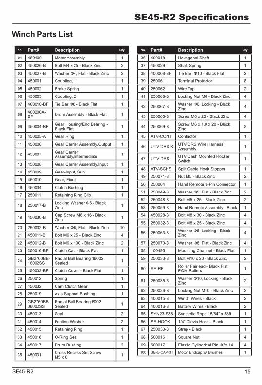
Winch Parts List
No. Part# Description Qty.
01 450100 Motor Assembly 1
02 450026-B Bolt M4 x 25 - Black Zinc 2
03 450027-B Washer Φ4, Flat - Black Zinc 2
04 450001 Coupling, 1 1
05 450002 Brake Spring 1
06 450003 Coupling, 2 1
07 400010-BF Tie Bar Φ8 - Black Flat 1
08 400200A-BF Drum Assembly - Black Flat 1
09 450004-BF Gear Housing/End Bearing - Black Flat 1
10 450005-A Gear Ring 1
11 450006 Gear Carrier Assembly,Output 1
12 450007 Gear Carrier Assembly,Intermediate 1
13 450008 Gear Carrier Assembly,Input 1
14 450009 Gear-Input, Sun 1
15 450010 Gear, Fixed 1
16 450034 Clutch Bushing 1
17 250011 Retaining Ring Clip 1
18 250017-B Locking Washer Φ6 - Black Zinc 1
19 450030-B Cap Screw M6 x 16 - Black Zinc 1
20 250002-B Washer Φ6, Flat - Black Zinc 10
21 450011-B Bolt M6 x 25 - Black Zinc 4
22 450012-B Bolt M6 x 100 - Black Zinc 2
23 250016-BF Clutch Cap - Black Flat 1
24 GB2760BB-16002SS
Radial Ball Bearing 16002 Sealed 1
25 450033-BF Clutch Cover - Black Flat 1
26 250012 Spring 1
27 450032 Cam Clutch Gear 1
28 250019 Axis Support Bushing 1
29 GB2760BB-06002SS
Radial Ball Bearing 6002 Sealed 1
30 450013 Seal 2
31 450014 Friction Washer 2
32 450015 Retaining Ring 1
33 450016 O-Ring Seal 1
34 450017 Drum Bushing 2
35 450031 Cross Recess Set Screw M5 x 8 1
No. Part# Description Qty.
36 400018 Haxagonal Shaft 1
37 450029 Shaft Spring 1
38 400008-BF Tie Bar Φ10 - Black Flat 2
39 250061 Terminal Protector 8
40 250062 Wire Tap 2
41 250068-B Locking Nut M6 - Black Zinc 4
42 250067-B Washer Φ6, Locking - Black Zinc 4
43 250065-B Screw M6 x 25 - Black Zinc 4
44 250069-B Screw M6 x 1.0 x 20 - Black Zinc 2
45 ATV-CONT Contactor 1
46 UTV-DRS-K UTV-DRS Wire Harness Assembly 1
47 UTV-DRS UTV Dash Mounted Rocker Switch 1
48 ATV-SCHS Split Cable Hook Stopper 1
49 250071-B Nut M5 - Black Zinc 2
50 250064 Hand Remote 3-Pin Connector 1
51 250049-B Washer Φ5, Flat - Black Zinc 2
52 250048-B Bolt M5 x 25 - Black Zinc 2
53 250059-B Hand Remote Assembly - Black 1
54 450028-B Bolt M8 x 30 - Black Zinc 4
55 250032-B Bolt M8 x 25 - Black Zinc 4
56 250063-B Washer Φ8, Locking - Black Zinc 4
57 250070-B Washer Φ8, Flat - Black Zinc 4
58 100495 Mounting Channel - Black Flat 1
59 250033-B Bolt M10 x 20 - Black Zinc 2
60 SE-RF Roller Fairlead - Black Flat, POM Rollers 1
61 250035-B Washer Φ10, Locking - Black Zinc 2
62 250036-B Locking Nut M10 - Black Zinc 2
63 400015-B Winch Wires - Black 2
64 400016-B Battery Wires - Black 2
65 SYN23-S38 Synthetic Rope 15/64” x 38ft 1
66 SE-HOOK 1/4” Clevis Hook - Black 1
67 250030-B Strap - Black 1
68 500016 Square Nut 4
69 500017 Elastic Cylindrical Pin Φ3x 14 4
100 SE-U-CAPKIT Motor Endcap w/ Brushes 1
16 SE45-R2
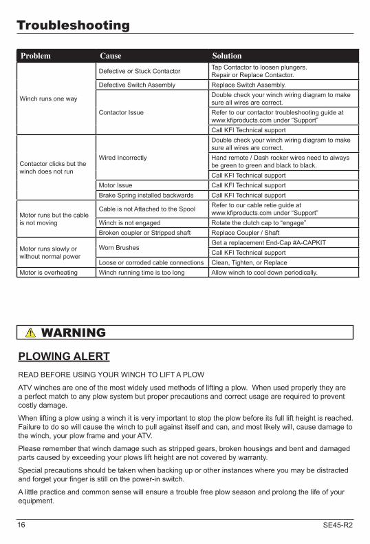
Troubleshooting
Problem Cause Solution
Winch runs one way
Defective or Stuck Contactor Tap Contactor to loosen plungers.Repair or Replace Contactor.
Defective Switch Assembly Replace Switch Assembly.
Contactor Issue
Double check your winch wiring diagram to make sure all wires are correct.Refer to our contactor troubleshooting guide at www.kfiproducts.com under “Support”Call KFI Technical support
Contactor clicks but the winch does not run
Wired Incorrectly
Double check your winch wiring diagram to make sure all wires are correct.Hand remote / Dash rocker wires need to always be green to green and black to black.Call KFI Technical support
Motor Issue Call KFI Technical support Brake Spring installed backwards Call KFI Technical support
Motor runs but the cable is not moving
Cable is not Attached to the Spool Refer to our cable retie guide at www.kfiproducts.com under “Support”
Winch is not engaged Rotate the clutch cap to “engage” Broken coupler or Stripped shaft Replace Coupler / Shaft
Motor runs slowly or without normal power
Worn BrushesGet a replacement End-Cap #A-CAPKITCall KFI Technical support
Loose or corroded cable connections Clean, Tighten, or ReplaceMotor is overheating Winch running time is too long Allow winch to cool down periodically.
WARNING
PLOWING ALERTREAD BEFORE USING YOUR WINCH TO LIFT A PLOW
ATV winches are one of the most widely used methods of lifting a plow. When used properly they are a perfect match to any plow system but proper precautions and correct usage are required to prevent costly damage.
When lifting a plow using a winch it is very important to stop the plow before its full lift height is reached. Failure to do so will cause the winch to pull against itself and can, and most likely will, cause damage to the winch, your plow frame and your ATV.
Please remember that winch damage such as stripped gears, broken housings and bent and damaged parts caused by exceeding your plows lift height are not covered by warranty.
Special precautions should be taken when backing up or other instances where you may be distracted and forget your finger is still on the power-in switch.
A little practice and common sense will ensure a trouble free plow season and prolong the life of your equipment.

17SE45-R2
KAPPERS FABRICATING INC�ONE YEAR LIMITED WARRANTYEffective April 1, 2012
Warranty QualificationsKappers Fabricating Inc. (KFI) will register this warranty upon receipt of your Warranty Reg-istration Card and a copy of your sales receipt from one of KFI’s resale locations as proof of purchase.
Please submit your warranty registration and your proof of purchase within Fifteen (15) days of the date of purchase.
Repair/Replacement WarrantyKFI warrants to the original purchaser that the mechanical and electrical components will be free of defects in material and workmanship for a period of one (1) year from the original date of purchase (90 days for commercial & industrial use). Transportation charges on product submitted for repair or replacement under this warranty are the sole responsibility of the purchaser. This warranty only applies to the original purchaser and is not transferable.
Do not return the unit to the place of purchaseContact KFI’s Technical Service and KFI will troubleshoot any issue via phone or e-mail. If the problem is not corrected by this method, KFI will, at its option, authorize evaluation, repair or replacement of the defective part or component at a KFI Service Center. KFI will provide you with a case number for warranty service. Please keep it for future reference. Repairs or replacements without prior authorization, or at an unauthorized repair facility, will not be covered by this warranty.
Warranty ExclusionsThis warranty does not cover the following repairs and equipment:
Normal WearWinches need periodic parts and service to perform well. This warranty does not cover repair when normal use has exhausted the life of a part or the equipment as a whole.
Installation, Use and MaintenanceThis warranty will not apply to parts and/or labor if this winch is deemed to have been misused, neglected, involved in an accident, abused, loaded beyond the winch’s limits, modified, installed improperly or connected incorrectly to any electrical component. Normal maintenance is not covered by this warranty.
Other ExclusionsThis warranty excludes:• The winch cable.• Cosmetic defects such as paint, decals, etc.• Accessory parts such as storage covers.• Failures due to acts of God and other force
majeure events beyond the manufacturer’s control.
• Problems caused by parts that are not original Kappers Fabricating Inc.
• Cable Stacking and Water Submersion
Limits of Implied Warranty and Consequential DamageKappers Fabricating Inc. disclaims any obligation to cover any loss of time, use of this product, freight, or any incidental or consequential claim by anyone from using this winch. THIS WARRANTY IS IN LIEU OF ALL OTHER WARRANTIES, EXPRESS OR IMPLIED, INCLUDING WARRANTIES OF MERCHANT-ABILITY OR FITNESS FOR A PARTICULAR PURPOSE
A unit provided as an exchange will be subject to the warranty of the original unit. The length of the warranty governing the exchanged unit will remain calculated by reference to the purchase date of the original unit.
This warranty gives you certain legal rights which may change from state to state. Your state may also have other rights you may be entitled to that are not listed within this warranty.
WarrantyWarranty

18 SE45-R2
Contact Information
AddressKFI ProductsWinch Customer ServiceP�O� Box 32721 Sata DriveSpring Valley, MN 55975
Corporate:Kappers Fabricating Inc�1015 Industrial Dr�P�O� Box 32Spring Valley, MN 55975
Agreement
By purchasing and/or using any item from KFI and/or its parent company, the purchaser acknowl-edges to be at least 18 years of age� Purchaser also acknowledges that winch products are inherently dangerous and hazardous, and that use of the product involves the risk and danger of serious bodily injury including, but not limited to, disability, paralysis, dismemberment and death� Additional risks may exist that may not be readily foreseeable�
Purchaser agrees to comply with all applicable laws governing the use of the product, and to observe all appropriate safety precautions, including the wearing of appropriate protective gear and clothing, and operating the product safely and under safe conditions�
Purchaser fully accepts and assumes responsibility for all such risks, losses, costs, and damages incurred as a result of the use of the product, whether by purchaser or anyone using the product with or without purchaser’s permission�
Your purchase of the product shall constitute your release and indemnity in favor of KFI and/or or its parent company, its shareholders, officers, directors and employees from any and all claims or injuries of every kind resulting from use or operation of the product, including costs and attorney’s fees incurred in connection therewith�
Warranty
Customer Service
Mon – Thur 8:00 AM – 5:00 PM (CST/CDT)Fri 7:00 AM – 1:00 PM (CST/CDT)Toll Free: 1-877-346-2050 Option #1Fax no�: 1-507-346-2010sales@kfiproducts�com
Technical Service
Mon – Thur 8:00 AM – 5:00 PM (CST/CDT)Fri 7:00 AM – 1:00 PM (CST/CDT)Toll Free: 1-877-346-2050 Option #2tech@kfiproducts�com
19SE45-R2
Sharp edges and rough surfaces will shorten cable life. Inspect the cable and protective sleeve before use. Replace cable immediately if the cable has cut strands, fused or melted fibers, odd stiff sections, chemical contaminated, flat areas or lumps that cannot be eliminated after flexing the cable.
DANGER
Do not tie the cable to secure a load or connect a broken cable. Do not expose the cable to chemicals or heat sources. Do not run the cable over sharp edges or rough surfaces.
WARNING
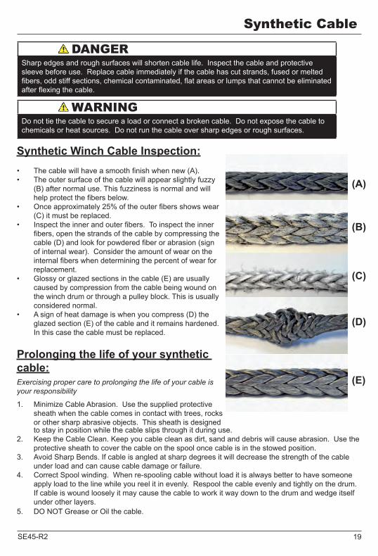
Synthetic Winch Cable Inspection:• The cable will have a smooth finish when new (A). • The outer surface of the cable will appear slightly fuzzy
(B) after normal use. This fuzziness is normal and will help protect the fibers below.
• Once approximately 25% of the outer fibers shows wear (C) it must be replaced.
• Inspect the inner and outer fibers. To inspect the inner fibers, open the strands of the cable by compressing the cable (D) and look for powdered fiber or abrasion (sign of internal wear). Consider the amount of wear on the internal fibers when determining the percent of wear for replacement.
• Glossy or glazed sections in the cable (E) are usually caused by compression from the cable being wound on the winch drum or through a pulley block. This is usually considered normal.
• A sign of heat damage is when you compress (D) the glazed section (E) of the cable and it remains hardened. In this case the cable must be replaced.
Prolonging the life of your synthetic cable:Exercising proper care to prolonging the life of your cable is your responsibility
1. Minimize Cable Abrasion. Use the supplied protective sheath when the cable comes in contact with trees, rocks or other sharp abrasive objects. This sheath is designed to stay in position while the cable slips through it during use.
2. Keep the Cable Clean. Keep you cable clean as dirt, sand and debris will cause abrasion. Use the protective sheath to cover the cable on the spool once cable is in the stowed position.
3. Avoid Sharp Bends. If cable is angled at sharp degrees it will decrease the strength of the cable under load and can cause cable damage or failure.
4. Correct Spool winding. When re-spooling cable without load it is always better to have someone apply load to the line while you reel it in evenly. Respool the cable evenly and tightly on the drum. If cable is wound loosely it may cause the cable to work it way down to the drum and wedge itself under other layers.
5. DO NOT Grease or Oil the cable.
Synthetic Cable
(A)
(B)
(C)
(D)
(E)

1-877-346-2050KFI ProductsP.O. Box 32
721 Sata DriveSpring Valley, MN 55975
www.kfiproducts.comMade in China
©2012 Kappers Fabricating Inc.
Corporate Office:Kappers Fabricating Inc.
P.O. Box 321015 Industrial Drive
Spring Valley, MN 55975 USA