owner's manual - fimco industriesfm356).pdf · model: lss-280 (5300467) (200 gallon lawn...
TRANSCRIPT

Warranty/Parts/ServiceProducts are warranted for one year from date of purchase against manufacturer or workmanship defects.
Commercial users have a 90 day warranty.
Your authorized dealer is the best source of replacement parts and service. To obtain prompt, efficient service, always remember to give the following information...
- Correct Part Description and/or part number. - Model number/Serial number of your sprayer.
Part descriptions and part numbers can be obtained from the illustrated parts list section(s) of this manual.
Whenever you need parts or repair service, contact your distributor/dealer first. For warranty work, always take your original sales slip, or other evidence of purchase date, to your distributor/dealer.
• 5.5 Horsepower Recoil Start Engine• 8 Roller Cast Iron Pump• 10 Gallons Per Minute at 250 PSI• Pressure Gauge-Adjustable Pressure Range• Suction Line Filter• Handgun-300' Handgun 1/2" Hose• Dual Jet Agitation
Technical Specifications
Form No. 356 [5004293 (04/13)] Printed in the U.S.A.
Model: LSS-280 (5300467)(200 Gallon Lawn Service Skid Sprayer)
Owner's Manual
Add gas and oil to the engine as specified in the engine manual. Check the side port of the engine gear case for lubricant. Add more lubricant if necessary. See the engine manual for type of lubricant needed.
It is important to test the sprayer with plain water before attempting actual spraying. This will enable you to check the completed sprayer for leaks in the plumbing system.
1. Open tank lid and be sure the tank is clean and free of foreign material. Fill the tank about one half full with plain water.2. Open the valve in the strainer assembly and allow water to flow to the pump. (The valve is located at this point to enable the strainer to be taken apart for cleaning.)
CAUTION: Always be sure that water has reached the roller pump before starting your sprayer. If the pump is run dry, serious damage to the pump will result.
3. It is always best to start the sprayer at little or no pressure. This sprayer is equipped with a spring loaded relief valve. Turn the valve handle out to decrease pressure and in for increased pressure. The location of the relief valve and other important components may be found by referring to the exploded view drawings.4. The pumping system includes an agitator which will help keep the solution in suspension. Pressure to the agitator should never exceed 100 PSI. When spraying at pressures over 100 PSI, use the brass valve (in the hose reel/agitator plumbing assembly) to throttle the pressure to the agitator by closing the valve. As solution is forced through the agitator, the venturi action triples the flow through the agitator. The valve in the line may shut off the agitation completely when not needed, or it can throttle the amount of solution going to the agitator if too much agitation occurs.5. You may now start the sprayer engine following the engine manufacturers instructions. Let the sprayer run at low pressure until water has reached the handgun, and all air has been purged from the handgun line.6. The pressure should now be increased to 30-40 PSI. Operate the sprayer at this increased pressure for 3-5 minutes, thoroughly testing the unit before adding chemicals.7. The sprayer should now be ready for adding chemicals.
Operation
1000 FIMCO Lane, P.O. Box 1700, North Sioux City, SD 57049Toll Free Phone: 800-831-0027 : Toll Free Fax: 800-494-0440
www.fimcoindustries.com
General InformationThank you for purchasing this product. The purpose of this manual is to assist you in operating and maintaining your skid sprayer. Please read it carefully, as it furnishes information which will help you achieve years of trouble-free operation.
Operation
Col
or C
oded
Noz
zle
Inse
rts
White
Black
BlueRed
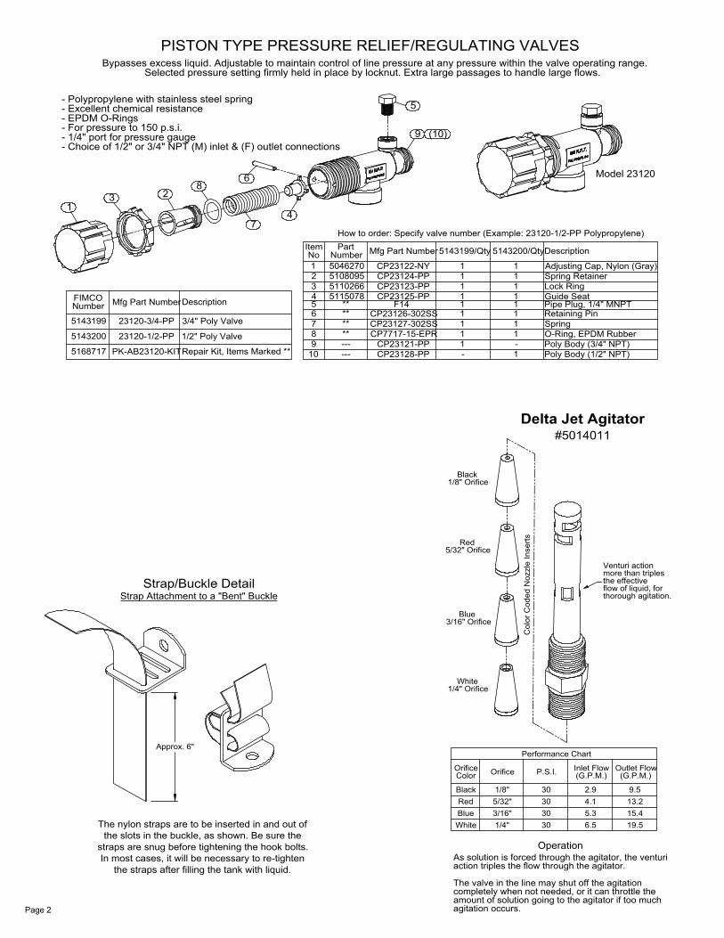
ColorOrifice
1/4"3/16"5/32"1/8"
Orifice
30
P.S.I.
303030
6.55.34.12.9
(G.P.M.)Inlet Flow
19.515.413.29.5
(G.P.M.)Outlet Flow
amount of solution going to the agitator if too muchcompletely when not needed, or it can throttle theThe valve in the line may shut off the agitation
action triples the flow through the agitator.As solution is forced through the agitator, the venturi
agitation occurs.
Performance Chart
Delta Jet Agitator
1/4" OrificeWhite
3/16" Orifice
5/32" Orifice
Blue
Red
1/8" OrificeBlack
thorough agitation.flow of liquid, forthe effectivemore than triplesVenturi action
#5014011
PISTON TYPE PRESSURE RELIEF/REGULATING VALVES
How to order: Specify valve number (Example: 23120-1/2-PP Polypropylene)
Model 23120
Selected pressure setting firmly held in place by locknut. Extra large passages to handle large flows.Bypasses excess liquid. Adjustable to maintain control of line pressure at any pressure within the valve operating range.
5115078511026651080955046270
PK-AB23120-KIT
23120-1/2-PP
23120-3/4-PP
Mfg Part Number
- Choice of 1/2" or 3/4" NPT (M) inlet & (F) outlet connections- 1/4" port for pressure gauge- For pressure to 150 p.s.i.
- Excellent chemical resistance- Polypropylene with stainless steel spring
5143199
5168717
5143200
NumberFIMCO
13
- EPDM O-Rings
6
Repair Kit, Items Marked **
3/4" Poly Valve
1/2" Poly Valve
Description
28
**7
1098
------**
Item
74
PartNumber
3
56
4
12
No
****
Poly Body (1/2" NPT)Poly Body (3/4" NPT)O-Ring, EPDM Rubber
Retaining PinPipe Plug, 1/4" MNPT
Spring RetainerAdjusting Cap, Nylon (Gray)
5143199/Qty
1CP23127-302SS
CP23128-PPCP23121-PP
CP7717-15-EPR
-11
CP23126-302SS
CP23125-PPCP23123-PPCP23124-PPCP23122-NY
Mfg Part Number
F14
1
111
11
Spring1
1
1-
5143200/Qty
1
111
11
Description
Guide SeatLock Ring
9
5
(10)
Strap Attachment to a "Bent" Buckle
Approx. 6"
Strap/Buckle Detail
The nylon straps are to be inserted in and out of the slots in the buckle, as shown. Be sure the
straps are snug before tightening the hook bolts. In most cases, it will be necessary to re-tighten
the straps after filling the tank with liquid.
Page 2
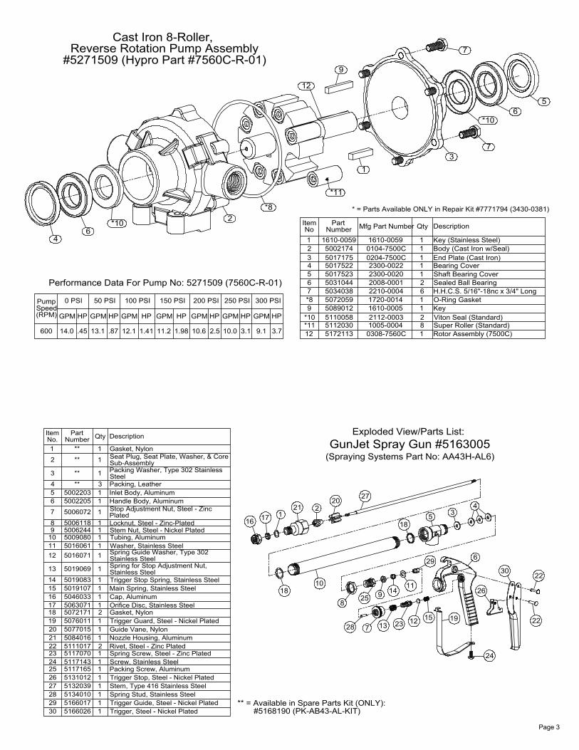
Performance Data For Pump No: 5271509 (7560C-R-01)
* = Parts Available ONLY in Repair Kit #7771794 (3430-0381)
#5271509 (Hypro Part #7560C-R-01)Reverse Rotation Pump Assembly
.87
HP
50 PSI
6
14.0
GPM
600
(RPM)SpeedPump
4
.45
HP
0 PSI
13.1
GPM
10.6
GPM
200 PSI
12.1
GPM
100 PSI
1.41
HP
1.98
HP
150 PSI
11.2
GPM
3.1
HP
250 PSI
2.5
HP
10.0
GPM GPM
300 PSI
9.1 3.7
HP
Cast Iron 8-Roller,
*10 2*8
Rotor Assembly (7500C)Super Roller (Standard)Viton Seal (Standard)
O-Ring GasketH.H.C.S. 5/16"-18nc x 3/4" LongSealed Ball BearingShaft Bearing Cover
End Plate (Cast Iron)Body (Cast Iron w/Seal)Key (Stainless Steel)
0308-7560C1005-00042112-00031610-00051720-00142210-00042008-00012300-00202300-0022
0204-7500C0104-7500C1610-0059
51721135112030511005850890125072059503403850310445017523501752250171755002174
1610-0059
7
*1112
*109*8
4
65
321
Key
Bearing Cover
6
81
211
1
21
111
Mfg Part Number
*11
NumberPart
NoItem
1
12
9
DescriptionQty
3
7
*10
7
65
23
Exploded View/Parts List:GunJet Spray Gun #5163005No. Number
Seat Plug, Seat Plate, Washer, & Core
Packing Washer, Type 302 Stainless
Inlet Body, AluminumHandle Body, AluminumStop Adjustment Nut, Steel - Zinc
Locknut, Steel - Zinc-PlatedStem Nut, Steel - Nickel PlatedTubing, AluminumWasher, Stainless SteelSpring Guide Washer, Type 302
Spring for Stop Adjustment Nut,
Trigger Stop Spring, Stainless SteelMain Spring, Stainless Steel
Orifice Disc, Stainless Steel
Trigger Guard, Steel - Nickel PlatedGuide Vane, NylonNozzle Housing, AluminumRivet, Steel - Zinc PlatedSpring Screw, Steel - Zinc PlatedScrew, Stainless SteelPacking Screw, AluminumTrigger Stop, Steel - Nickel PlatedStem, Type 416 Stainless SteelSpring Stud, Stainless SteelTrigger Guide, Steel - Nickel PlatedTrigger, Steel - Nickel Plated
21 5084016 1211111111
27 513203951340105166017516602630
2829
51110175117070511714351171655131012
242526
2223
10 5009080 111
1
1111211
15 501910750460335063071507217150760115077015
181920
1617
50160615016071
5019069
5019083
13
14
1112
Cap, Aluminum
Gasket, Nylon
Stainless Steel
Stainless Steel
1
1
1
311
1
11
5 50022035002205
5006072
50061185006244
7
89
6
3
4
1
2
**
**
**
**
Plated
Gasket, Nylon
Sub-Assembly
Packing, LeatherSteel
** = Available in Spare Parts Kit (ONLY): #5168190 (PK-AB43-AL-KIT)
1716
1018 14
7
25
28
8
13
9
20
121 2
27
QtyItem Part Description
24
11
1512 19
29
26
6
30
518
34
22
22
(Spraying Systems Part No: AA43H-AL6)
Page 3

Exploded ViewLSS-280 (5300467)
7
39
29
32
29
14
13 23 23
10 23 23
1
20
27
19
34
11
2
26
30
26
33
12
27
18328
16
16
9 22 22
2424
2424
4 15 24 24
5
36.1
36.5
36.7
36.6
36.2
36.236.5
36.3
36.4.136.4.236.4.336.4.4
6
21
35
17
2
31
38.2
38.5
38.3
38.4
38.1
29
3
28
18
37.2
37.737.1
37.137.3
37.1
37.4
37.537.6
31
25
8
Page 4

5
4
7
2
6
12
111
8
10
9
3
8-Roller Cast Iron Pump (Reverse Rotation)5.5 H.P. Engine w/ Gear Reduction
3/16" Square Keystock x 1 3/8" Long1/4" Square Keystock x 1 1/4" LongPoly Fitting, 3/4" MNPT x 3/4" HBRubber-Headed Machine Screw Bumper (#10-24)5/16"-18 x 5/8" Flange Lock Screw
#10-24 Hex Whiz (Flange) Locknut
Pump/Engine Sub-Assembly
PartItem
12111098765
321
No
5040004
527150951520995120044508903350890035067127
50345315023052501602650061865005177Number
4 Torque BracketLockwasher, 5/16"
Adapter & Kit (Coupler)
Description
2
Shield1
11
1
11
2
12
2
Qty
1
#5275145
Page 5
Parts List: LSS-280 (5300467)
After use, fill the sprayer tank part way with water. Start the sprayer, and allow the clear water to be pumped through the plumbing system and out through the spray nozzles.Refill the tank about half full with plain water and use FIMCO Tank Neutralizer and Cleaner, and repeat cleaning instructions above.Flush the entire sprayer with the neutralizing/cleaning agent, then flush out one more time with plain water. Follow the chemical manufacturer's disposal instructions of all wash or rinsing water.For the boom, (if applicable) remove the tips and screens from the nozzle assemblies. Wash these items out thoroughly. Blow the orifice clean and dry. If the orifice remains clogged, clean it with a fine bristle (NOT WIRE) brush, or with a toothpick. Do not damage the orifice. Water rinse and dry the tips before storing.
WARNING: Some chemicals will damage the pump valves if allowed to soak untreated for a length of time! ALWAYS flush the pump as instructed after each use.
After Spraying
Drain all water out of your sprayer, paying special attention to the pump, handgun, and valve(s). These items are especially prone to damage from chemicals and freezing weather.
The sprayer should be winterized before storage by pumping a solution of RV antifreeze through the entire plumbing system. This antifreeze solution should remain in the plumbing system during the winter months. When spring time comes and you are preparing your sprayer for the spray season, rinse the entire plumbing system out, clearing the lines of the antifreeze solution. Proper care and maintenance will prolong the life of your sprayer.
Winter Storage
Item No Part Number Qty Description1 5006306 4 1/4"-20 Hex Whiz (Flange) Locknut2 5006307 12 5/16"-18 Hex Whiz (Flange) Locknut3 5006337 4 1/2"-13 Hex Whiz (Flange) Locknut4 5010207 1 Poly Elbow, 3/4" MNPT x 1/2" HB5 5010214 1 Poly Elbow, 1 1/4" MNPT x 3/4" HB (3EL11434)6 5011126 1 1/4" x 4 1/2" Galv. Pipe Nipple7 5014011 1 Delta Jet Agitator8 5016066 1 Garden Hose Washer9 5020117 1 Hose, 5/8"-1 Brd. x 48"
10 5020211 1 Hose, 3/4"-2 Brd. x 60"11 5020291 1 Hose, 1/2"-2 Brd. x 30"12 5020309 1 Hose, 1/2"-2 Brd. x 300 Ft.13 5020311 1 Hose, 3/4"-2 Brd. x 50"14 5020312 1 Hose, 1 1/4"-2 Brd. x 10"15 5020509 1 Hose, 1/2" EPDM x 5 Ft.16 5034038 8 H.H.C.S. 5/16"-18nc x 3/4" Long17 5034069 4 H.H.C.S., 5/16"-18 x 1 1/2" (Full Thread)18 5034111 4 1/2" x 6" Hook Bolt19 5034197 2 Round U-Bolt, 1/4"-20 x 1" x 1 3/4" (3/4" Thread)20 5038637 1 Handgun Holder Bracket21 5046057 1 1/4" N.P.T. Galv. Hex Pipe Cap22 5051023 2 Hose Clamp, 5/8"23 5051024 4 Hose Clamp, 3/4"24 5051114 6 Hose Clamp (3/8"-1/2")25 5056096 1 Poly Elbow, 11/16" U.N.F. x 5/8" HB26 5067052 2 Steel Fitting, 1/2" MNPT x 1/2" HB27 5075014 2 Rubber Grommet (Black)28 5108041 4 Tank Strap Buckle, Bent29 5133103 2 Nylon Strap (2" x 96")30 5163005 1 GunJet Spray Gun (AA43H-AL6)31 5167034 2 Gauge, Liquid-Filled, 0-400# p.s.i.32 5169004 1 200 Gallon Horizontal Tank (White)33 5272182 1 Manual Hose Reel34 5274195 1 Reel Mount Weldment35 5275145 1 Engine/Pump Sub-Assembly36 5275334 1 Strainer Assembly (LSS-280)
36.1 5006307 4 5/16"-18 Hex Whiz (Flange) Locknut36.2 5034065 2 Round U-Bolt, 5/16"-18 x 1 1/2" x 2 3/16"36.3 5038258 1 Strainer Bracket36.4 5116213 1 Strainer
36.4.1 3351-0039 1 Strainer Bowl36.4.2 5116131 1 Screen (40 Mesh)36.4.3 5072299 1 EPDM Gasket36.4.4 3351-0038 1 Strainer Cap36.5 5067127 2 Poly Fitting, 3/4" MNPT x 3/4" HB36.6 5011140 1 Poly Close Nipple, 3/4" MNPT36.7 5143190 1 3/4" "T-800" Brass Ball Valve37 5275335 1 Hose Reel/Agitator Plumbing Assembly (LSS-280)
37.1 5011046 3 1/2" Galvanized Close Nipple37.2 5010086 1 1/2" NPT Galvanized Tee37.3 5143197 1 1/2" T-800 Brass Ball Valve37.4 5067131 1 Poly Fitting, 1/2" MNPT x 1/2" HB37.5 5010230 1 Poly Tee, 1/2" FNPT37.6 5041073 1 Poly Reducing Bushing, 1/2" MNPT x 1/4" FNPT37.7 5067052 1 Steel Fitting, 1/2" MNPT x 1/2" HB38 5275336 1 Pressure Relief Valve Assembly
38.1 5011140 1 Poly Close Nipple, 3/4" MNPT38.2 5010257 1 Poly Gauge Tee, 3/4" FNPT38.3 5143199 1 Pressure Relief Valve, (3/4" NPT)38.4 5067126 1 Poly Fitting, 3/4" MNPT x 5/8" HB38.5 5067125 1 Poly Fitting, 3/4" MNPT x 1/2" HB39 5275770 1 200 Gal. Skid Weldment (Red)