oxidation technologies for stationary rich and … · oxidation technologies for stationary rich...
TRANSCRIPT

1
Oxidation Technologies forStationary Rich and Lean Burn Engines
ICAC – LADCOAdvancements in Emission Control
and Measurement Technologies for Industrial Applications
March 24-25, 2010Rosemont, IL
2
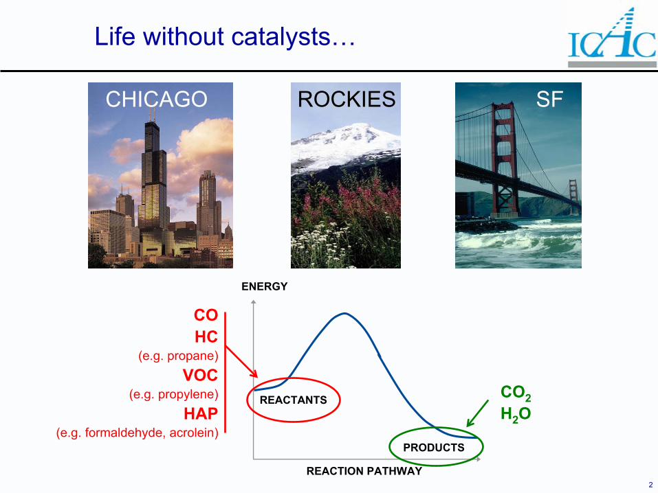
Life without catalysts…
REACTANTS
PRODUCTS
ENERGY
REACTION PATHWAY
COHC
(e.g. propane)VOC
(e.g. propylene)HAP
(e.g. formaldehyde, acrolein)
CHICAGO ROCKIES SF
CO2H2O
3
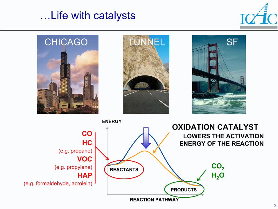
…Life with catalysts
COHC
(e.g. propane)VOC
(e.g. propylene)HAP
(e.g. formaldehyde, acrolein)
CHICAGO SF
CO2H2O
TUNNEL
REACTANTS
PRODUCTS
ENERGY
REACTION PATHWAY
OXIDATION CATALYSTLOWERS THE ACTIVATION
ENERGY OF THE REACTION
4
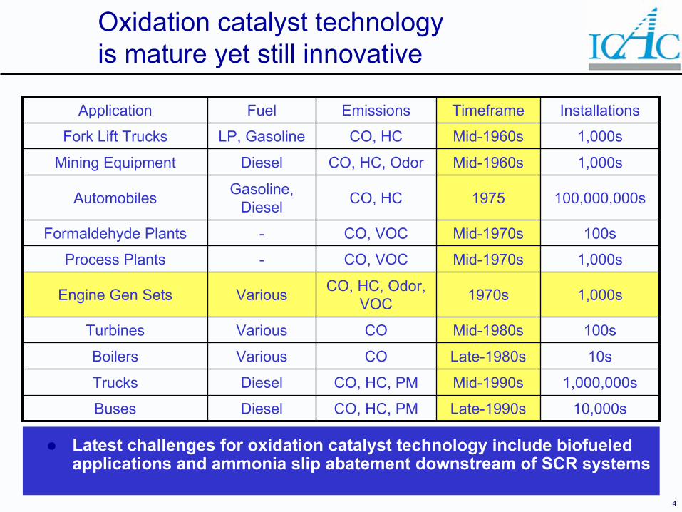
Oxidation catalyst technology is mature yet still innovative
10,000sLate-1990sCO, HC, PMDieselBuses
1,000,000sMid-1990sCO, HC, PMDieselTrucks
10sLate-1980sCOVariousBoilers
100sMid-1980sCOVariousTurbines
1,000s1970sCO, HC, Odor, VOCVariousEngine Gen Sets
1,000sMid-1970sCO, VOC-Process Plants
100sMid-1970sCO, VOC-Formaldehyde Plants
100,000,000s1975CO, HCGasoline, DieselAutomobiles
1,000sMid-1960sCO, HC, OdorDieselMining Equipment
1,000sMid-1960sCO, HCLP, GasolineFork Lift Trucks
InstallationsTimeframeEmissionsFuelApplication
Latest challenges for oxidation catalyst technology include biofueledapplications and ammonia slip abatement downstream of SCR systems

5
Overview
Oxidation catalyst technologies– NSCR (Three-way catalyst)– Diesel Oxidation Catalyst (DOC)– Oxidation Catalyst
Advances in emission control– Substrates– Systems– Selection
Applications on stationary engines– Case study
6
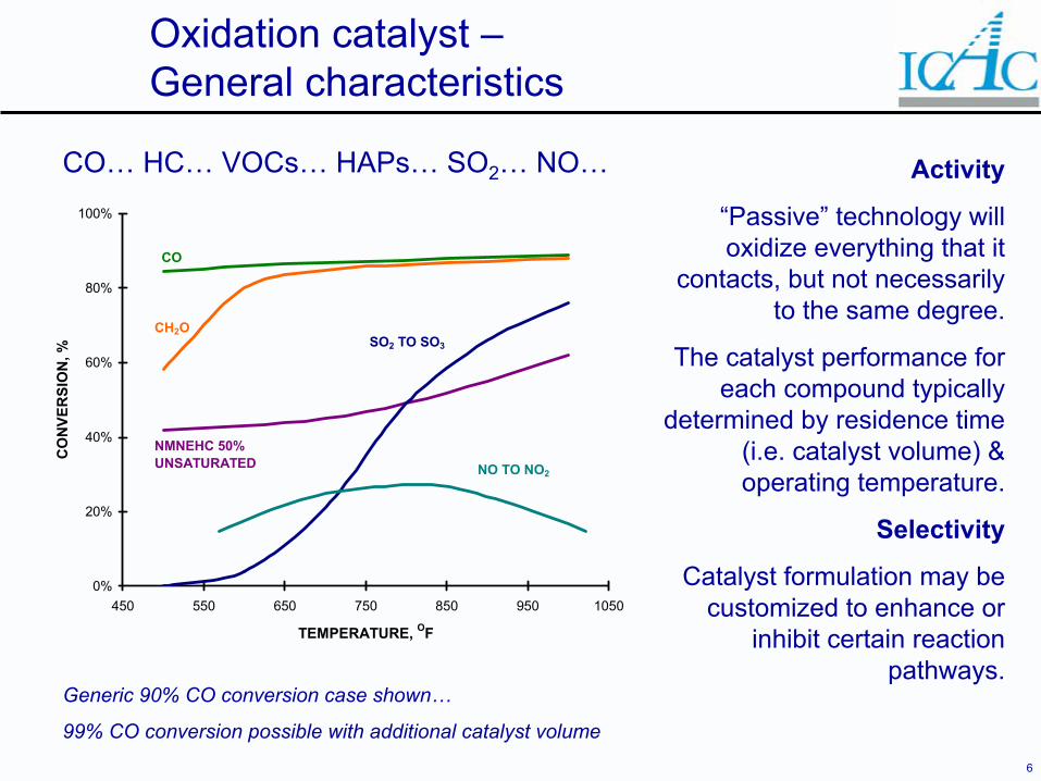
Oxidation catalyst –General characteristics
0%
20%
40%
60%
80%
100%
450 550 650 750 850 950 1050
TEMPERATURE, OF
CO
NVE
RSI
ON
, %
CO
NMNEHC 50% UNSATURATED
SO2 TO SO3
NO TO NO2
CH2O
Activity
“Passive” technology will oxidize everything that it
contacts, but not necessarily to the same degree.
The catalyst performance for each compound typically
determined by residence time (i.e. catalyst volume) & operating temperature.
Selectivity
Catalyst formulation may be customized to enhance or
inhibit certain reaction pathways.
CO… HC… VOCs… HAPs… SO2… NO…
Generic 90% CO conversion case shown…
99% CO conversion possible with additional catalyst volume
7
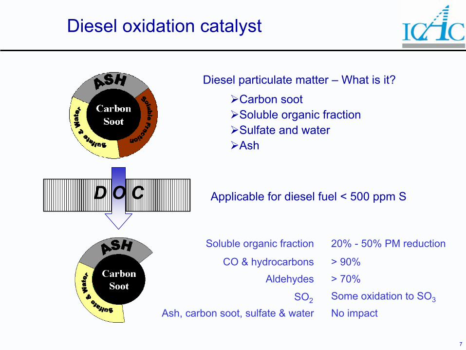
Diesel oxidation catalyst
Diesel particulate matter – What is it?
Carbon sootSoluble organic fractionSulfate and waterAsh
Applicable for diesel fuel < 500 ppm S
No impactAsh, carbon soot, sulfate & waterSome oxidation to SO3SO2
> 70%Aldehydes> 90%CO & hydrocarbons
20% - 50% PM reductionSoluble organic fraction
D O C
8
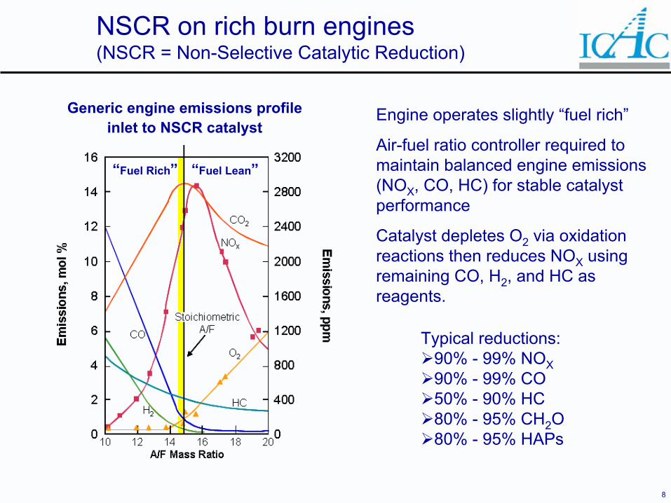
NSCR on rich burn engines(NSCR = Non-Selective Catalytic Reduction)
Typical reductions: 90% - 99% NOX90% - 99% CO50% - 90% HC80% - 95% CH2O80% - 95% HAPs
“Fuel Rich” “Fuel Lean”
Generic engine emissions profile inlet to NSCR catalyst
Engine operates slightly “fuel rich”
Air-fuel ratio controller required to maintain balanced engine emissions (NOX, CO, HC) for stable catalyst performance
Catalyst depletes O2 via oxidation reactions then reduces NOX using remaining CO, H2, and HC as reagents.
9
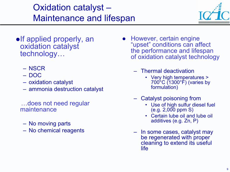
Oxidation catalyst –Maintenance and lifespan
If applied properly, an oxidation catalyst technology…
– NSCR – DOC – oxidation catalyst – ammonia destruction catalyst
…does not need regular maintenance
– No moving parts– No chemical reagents
However, certain engine “upset” conditions can affect the performance and lifespan of oxidation catalyst technology
– Thermal deactivation• Very high temperatures >
700°C (1300°F) (varies by formulation)
– Catalyst poisoning from• Use of high sulfur diesel fuel
(e.g. 2,000 ppm S)• Certain lube oil and lube oil
additives (e.g. Zn, P)
– In some cases, catalyst may be regenerated with proper cleaning to extend its useful life
10
Overview
Oxidation catalyst technologies– NSCR (Three-way catalyst)– Diesel Oxidation Catalyst (DOC)– Oxidation Catalyst
Advances in emission control– Substrates– Systems– Selection
Applications on stationary engines– Case study
11
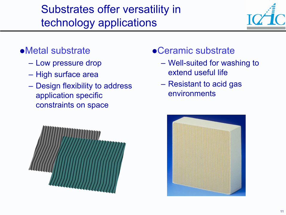
Substrates offer versatility in technology applications
Metal substrate– Low pressure drop– High surface area– Design flexibility to address
application specific constraints on space
Ceramic substrate– Well-suited for washing to
extend useful life– Resistant to acid gas
environments
12
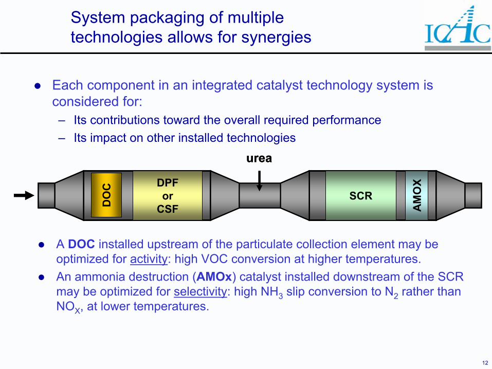
System packaging of multiple technologies allows for synergies
Each component in an integrated catalyst technology system is considered for:– Its contributions toward the overall required performance– Its impact on other installed technologies
A DOC installed upstream of the particulate collection element may beoptimized for activity: high VOC conversion at higher temperatures.An ammonia destruction (AMOx) catalyst installed downstream of the SCR may be optimized for selectivity: high NH3 slip conversion to N2 rather than NOX, at lower temperatures.
DO
C DPFor
CSFSCR
urea
AM
OX
DO
C DPFor
CSFSCR
urea
AM
OX
13
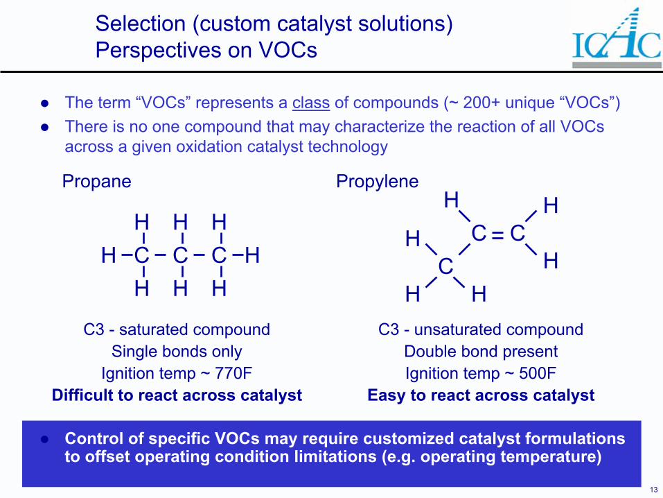
Selection (custom catalyst solutions) Perspectives on VOCs
The term “VOCs” represents a class of compounds (~ 200+ unique “VOCs”)There is no one compound that may characterize the reaction of all VOCsacross a given oxidation catalyst technology
C3 - saturated compoundSingle bonds only
Ignition temp ~ 770FDifficult to react across catalyst
Propylene
C CCH H H
H H HHH
C CC
HH
H
H
HH
Propane
C3 - unsaturated compoundDouble bond presentIgnition temp ~ 500F
Easy to react across catalyst
Control of specific VOCs may require customized catalyst formulations to offset operating condition limitations (e.g. operating temperature)
14
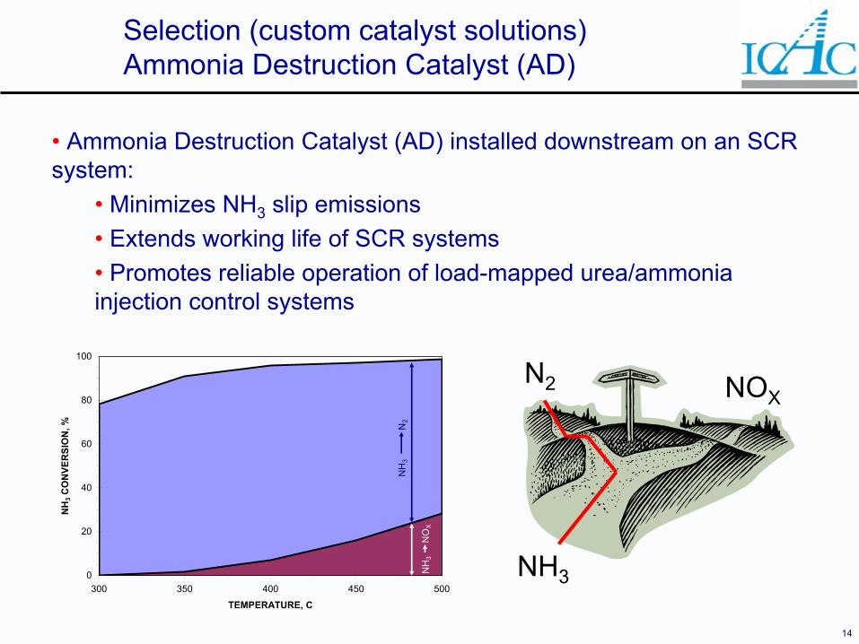
Selection (custom catalyst solutions) Ammonia Destruction Catalyst (AD)
• Ammonia Destruction Catalyst (AD) installed downstream on an SCR system:
• Minimizes NH3 slip emissions• Extends working life of SCR systems• Promotes reliable operation of load-mapped urea/ammonia injection control systems
NH3
N2 NOX
0
20
40
60
80
100
300 350 400 450 500
TEMPERATURE, C
NH
3 CO
NVE
RSI
ON
, %
NH
3
N2
NH
3
NO
X
15
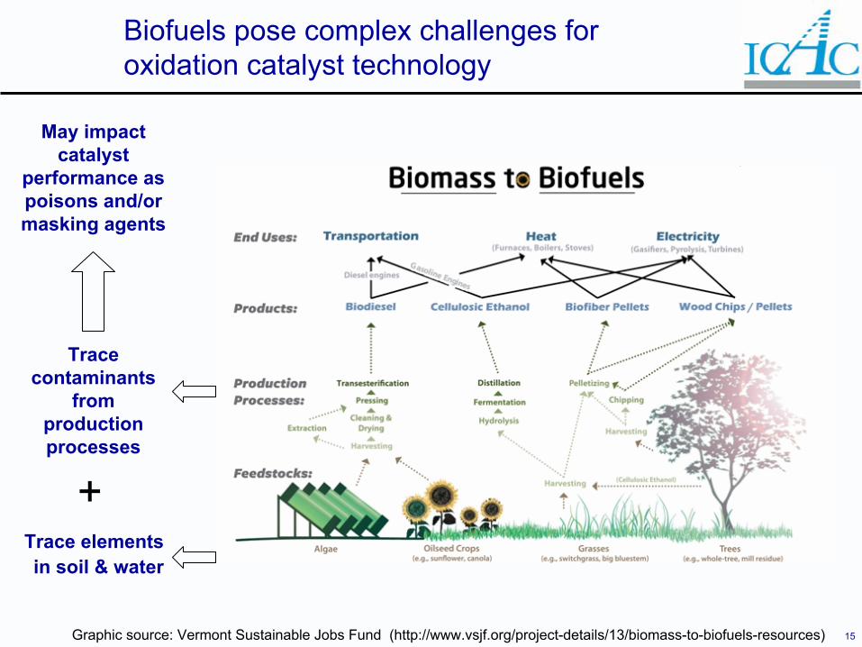
Biofuels pose complex challenges for oxidation catalyst technology
Graphic source: Vermont Sustainable Jobs Fund (http://www.vsjf.org/project-details/13/biomass-to-biofuels-resources)
Trace elementsin soil & water
Trace contaminants
from production processes
+
May impact catalyst
performance as poisons and/or masking agents
16
Selection (custom catalyst solutions) Biofuels for stationary engines
Catalyst issues posed by biofueled stationary engines:– Biodiesel Is An Effective Solvent, Can Dissolve Engine/Component
Deposits.– Ethanol Corrosive To Pipelines and Older Fuel Systems Components.– Trace Contaminants:
• Processing Catalysts: Na, K, Cu, Ni• Alkali Metals and Alkaline Earth Metals: Mg, Ca, Na, K
– Siloxanes Typical Contaminant in Landfill Gas.– Blends Often Used
• What Is The Real Fuel Specification?
Early adopters of oxidation catalyst technologies on biofueledstationary engines have been successful in EU (~ 200 engines)

17
Overview
Oxidation catalyst technologies– NSCR (Three-way catalyst)– Diesel Oxidation Catalyst (DOC)– Oxidation Catalyst
Advances in emission control– Substrates– Systems– Selection
Applications on stationary engines– Case study
18
EPA proposed air toxics limits on stationary engine emissions
On 2/26/10, EPA proposed setting emission limits for formaldehyde, benzene, acrolein and other air toxics from certain stationary diesel and gas-fired engines. For major sources of air toxics, this rule would only apply to engines that are: – Smaller than or equal to 500 horsepower that were constructed or
reconstructed before June 12, 2006, or – Larger than or equal to 500 horsepower that were constructed or
reconstructed before December 19, 2002. To meet the proposed emissions requirements, owners and operators of these engines would need to install "after treatment" controls, such as filters or catalysts, to engine exhaust systems, the agency said. The EPA estimates that this rule would reduce air toxics emissions by 13,000 tons per year, particle pollution by 2,600 tons and carbon monoxide emissions by 510,000 tons, when fully implemented in 2013.
Source: www.pollutionengineering.com

19
Case study:Acrolein emissions control
The problem… in 2005, a 1,000 hp, four stroke, stationary engine operating in Southern California is required to meet an acrolein (HAPs) stack emission requirement of 40 ppbv(wet).The solution… custom oxidation catalyst selected and subjected to slipstream reactor testing to prove its performance:– 3000 ppbv(wet) acrolein nominal inlet concentration– 40 ppbv(wet) acrolein required outlet concentration
• 98.6% acrolein nominal conversion efficiency– 950°F nominal engine stack temperature
• Slipstream reactor operates at 700 – 900F due to ambient cooling losses
– Acrolein measurements by GC/MS
20
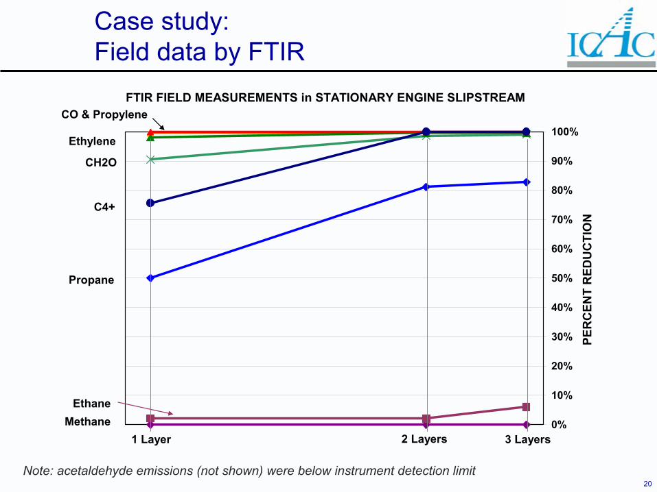
Case study:Field data by FTIR
Note: acetaldehyde emissions (not shown) were below instrument detection limit
FTIR FIELD MEASUREMENTS in STATIONARY ENGINE SLIPSTREAM
0%
10%
20%
30%
40%
50%
60%
70%
80%
90%
100%
PER
CEN
T R
EDU
CTI
ON
CO & Propylene
Ethylene
CH2O
C4+
Propane
EthaneMethane
3 Layers2 Layers1 Layer
21
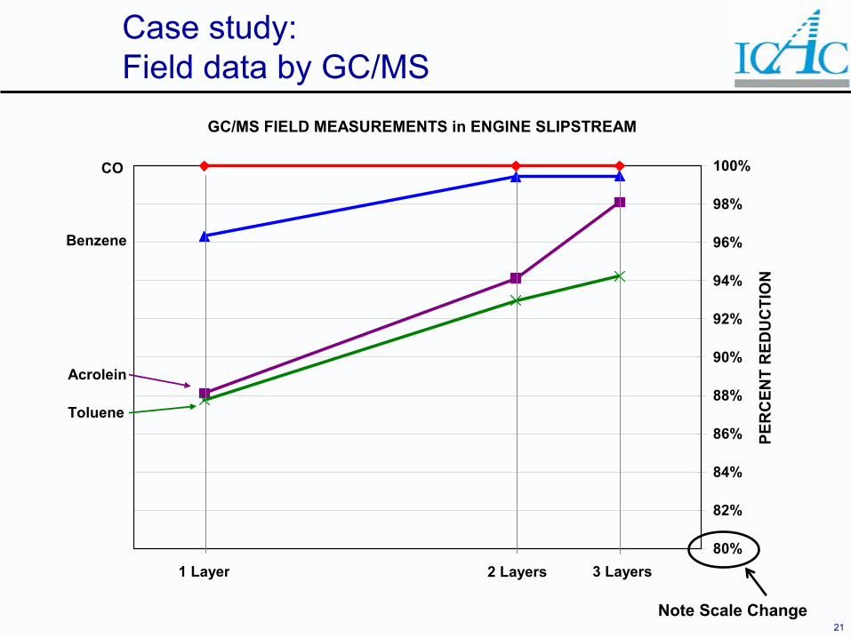
GC/MS FIELD MEASUREMENTS in ENGINE SLIPSTREAM
80%
82%
84%
86%
88%
90%
92%
94%
96%
98%
100%
PER
CEN
T R
EDU
CTI
ON
3 Layers2 Layers1 Layer
CO
Benzene
Acrolein
Toluene
Case study:Field data by GC/MS
Note Scale Change
22
Case study:Acrolein emissions control
The result… based on slipstream testing, three layers of oxidation catalyst were installed on the stationary engine.– Stack permit testing showed the acrolein emission to be 3
ppbv(wet), well below the 40 ppbv(wet) emission limit– Meaningful measurements below the nominal instrument
detection limit of 10 ppbv(wet) were possible due to significant hydrocarbon conversion that allowed for very clean chromatogram peaks.
– Engine stack temperature measured 1,000°F, a 20-40°F increase above nominal associated with catalyst backpressure
• Higher catalyst operating temperature = higher compound conversion rates
• Slipstream temperature profile through catalyst layers was less than actual application
Nominal 700°F – 890°F slipstream vs. 1000°F application
23
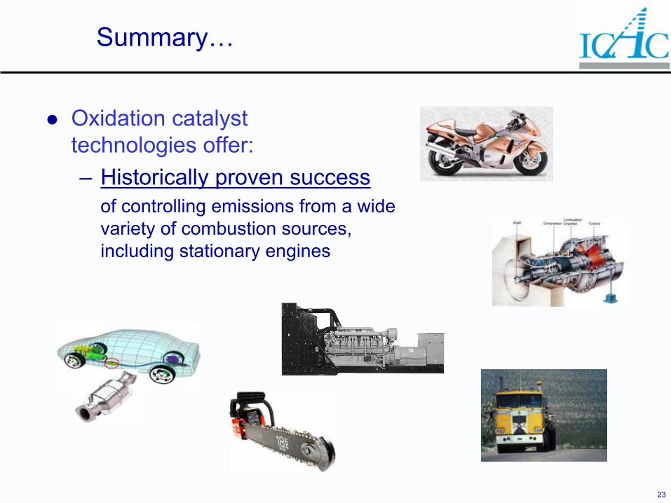
Summary…
Oxidation catalyst technologies offer:– Historically proven success
of controlling emissions from a widevariety of combustion sources, including stationary engines
24
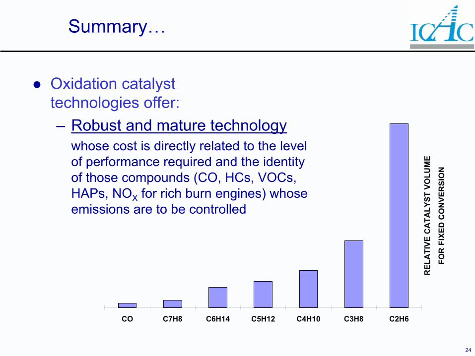
Summary…
Oxidation catalyst technologies offer:– Robust and mature technology
whose cost is directly related to the level of performance required and the identity of those compounds (CO, HCs, VOCs, HAPs, NOX for rich burn engines) whose emissions are to be controlled
CO C7H8 C6H14 C5H12 C4H10 C3H8 C2H6
REL
ATI
VE C
ATA
LYST
VO
LUM
E
FOR
FIX
ED C
ON
VER
SIO
N
25
Summary…
Oxidation catalyst technologies offer:– A future of continued innovation
into new applications and price/performance optimization of existing applications to ensure sustainable development
26
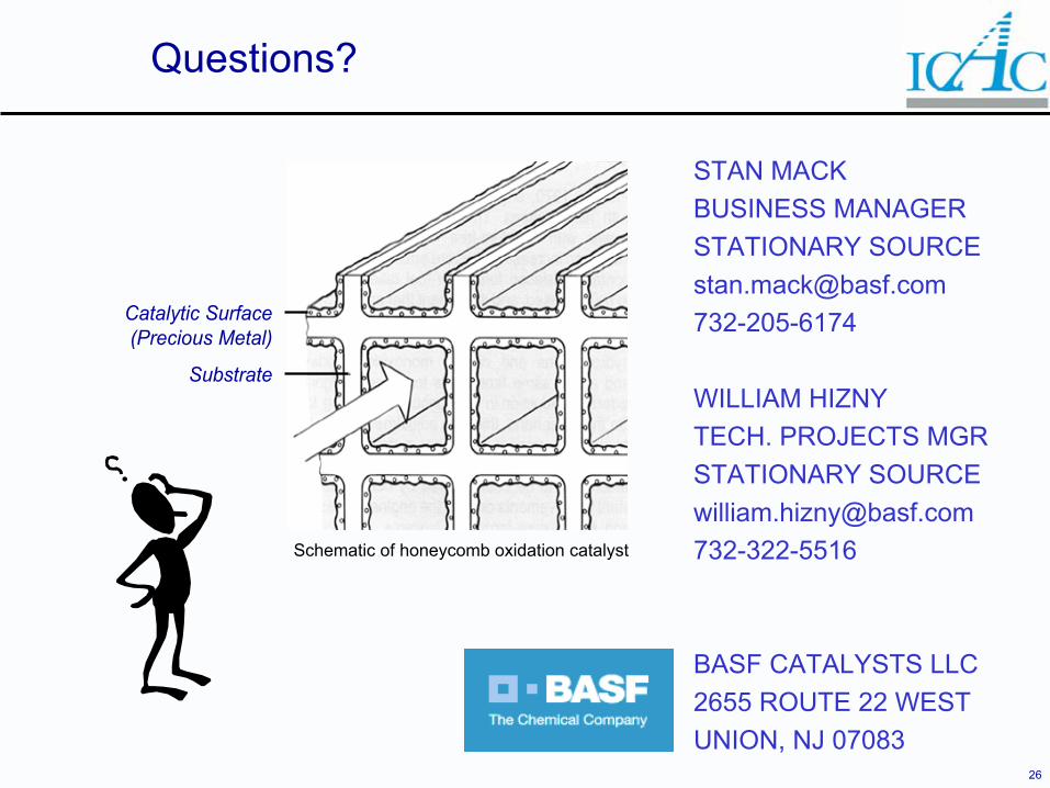
Questions?
STAN MACKBUSINESS MANAGERSTATIONARY [email protected]
WILLIAM HIZNYTECH. PROJECTS MGRSTATIONARY [email protected]
BASF CATALYSTS LLC2655 ROUTE 22 WESTUNION, NJ 07083
Catalytic Surface(Precious Metal)
Substrate
Schematic of honeycomb oxidation catalyst