ozone sounding with vaisala radiosonde rs41 user's guide
TRANSCRIPT

USER'S GUIDE
Ozone Sounding with Vaisala RadiosondeRS41
M211486EN-B

PUBLISHED BY
Visit our Internet pages at www.vaisala.com/
© Vaisala 2016
No part of this manual may be reproduced, published or publicly displayed in any form or by any means, electronic or mechanical (including photocopying), nor may its contents be modified, translated, adapted, sold or disclosed to a third party without prior written permission of the copyright holder. Translated manuals and translated portions of multilingual documents are based on the original English versions. In ambiguous cases, the English versions are applicable, not the translations.
The contents of this manual are subject to change without prior notice.
Local rules and regulations may vary and they shall take precedence over the information contained in this manual. Vaisala makes no representations on this manual’s compliance with the local rules and regulations applicable at any given time, and hereby disclaims any and all responsibilities related thereto.
This manual does not create any legally binding obligations for Vaisala towards customers or end users. All legally binding obligations and agreements are included exclusively in the applicable supply contract or the General Conditions of Sale and General Conditions of Service of Vaisala.
Vaisala OyjStreet address: Vanha Nurmijärventie 21, FI-01670 Vantaa,
FinlandMailing address: P.O.Box 26, FI-00421 Helsinki, FinlandPhone: +358 9 8949 1Fax: +358 9 8948 2227

________________________________________________________________________________
Table of Contents
CHAPTER 1GENERAL INFORMATION . . . . . . . . . . . . . . . . . . . . . . . . . . . . . . . . . . . . . .9
About This Manual . . . . . . . . . . . . . . . . . . . . . . . . . . . . . . . . .9Version Information . . . . . . . . . . . . . . . . . . . . . . . . . . . . . .11Related Manuals . . . . . . . . . . . . . . . . . . . . . . . . . . . . . . . .11Documentation Conventions . . . . . . . . . . . . . . . . . . . . . . .11
Product-Related Safety Precautions . . . . . . . . . . . . . . . . . .12Lithium Battery-Related Precautions . . . . . . . . . . . . . . . . .13Transporting RS41 Radiosondes with Lithium Batteries . . . . . . . . . . . . . . . . . . . . . . . . . . . . . . . . . . . . . . .13
ESD Protection . . . . . . . . . . . . . . . . . . . . . . . . . . . . . . . . . . .15Recycling . . . . . . . . . . . . . . . . . . . . . . . . . . . . . . . . . . . . . . . .15Trademarks . . . . . . . . . . . . . . . . . . . . . . . . . . . . . . . . . . . . . .15Product Returns . . . . . . . . . . . . . . . . . . . . . . . . . . . . . . . . . .16
CHAPTER 2PRODUCT AND SYSTEM COMPONENT OVERVIEW . . . . . . . . . . . . . . .17
Introduction to Ozone Sounding . . . . . . . . . . . . . . . . . . . .17Ozone Sensor Unit . . . . . . . . . . . . . . . . . . . . . . . . . . . . . . .18Ozone Interface Kit RSA411 . . . . . . . . . . . . . . . . . . . . . . .20
Ozone Interface Board OIF411 . . . . . . . . . . . . . . . . . . 21Radiosonde RS41 Additional Sensor Interface . . . . . . . . .24
Equipment and Material Needed . . . . . . . . . . . . . . . . . . . . .25Vaisala Ozone Sounding Startup Kit . . . . . . . . . . . . . . . . . .26
Ozonizer/Test Unit TSC-1 . . . . . . . . . . . . . . . . . . . . . . . . .27Ozone Destruction Filter . . . . . . . . . . . . . . . . . . . . . . . . . .30Pump Test Unit . . . . . . . . . . . . . . . . . . . . . . . . . . . . . . . . .31Laboratory Ware Set . . . . . . . . . . . . . . . . . . . . . . . . . . . . .33Ozone Chemicals . . . . . . . . . . . . . . . . . . . . . . . . . . . . . . . .34Air Flow Meter . . . . . . . . . . . . . . . . . . . . . . . . . . . . . . . . . .35
Using the Air Flow Meter . . . . . . . . . . . . . . . . . . . . . . . 35Other Equipment and Material . . . . . . . . . . . . . . . . . . . . . .38
Balance . . . . . . . . . . . . . . . . . . . . . . . . . . . . . . . . . . . . 38Thermometer . . . . . . . . . . . . . . . . . . . . . . . . . . . . . . . . 38Power Supply. . . . . . . . . . . . . . . . . . . . . . . . . . . . . . . . 38Protective Gloves. . . . . . . . . . . . . . . . . . . . . . . . . . . . . 38
Expendables and Spare Parts . . . . . . . . . . . . . . . . . . . . . .39
CHAPTER 3CONSTRUCTING AN OZONE SOUNDING . . . . . . . . . . . . . . . . . . . . . . . .41
Sounding Preparation Phases and Schedule . . . . . . . . . . .41
VAISALA________________________________________________________________________ 1

User’s Guide ______________________________________________________________________
Preparations 7 to 3 Days Prior to Release . . . . . . . . . . . . .43Preparation Steps . . . . . . . . . . . . . . . . . . . . . . . . . . . . . . .43
Preparations on the Day of Release . . . . . . . . . . . . . . . . . .46Preparation Steps . . . . . . . . . . . . . . . . . . . . . . . . . . . . . . .46
Preparations Just Before Release (2 - 0 Hours) . . . . . . . . .48Starting Preparations . . . . . . . . . . . . . . . . . . . . . . . . . . . . .49Attaching Radiosonde Holder to Flight Box . . . . . . . . . . . .49Attaching OIF411 to SPC’s Ozone Sensor Frame . . . . . . .53Attaching OIF411 to DMT’s Ozone Sensor Frame . . . . . .56Connecting Ozone Sensor Wires to OIF411 . . . . . . . . . . .58Preparing the Radiosonde and OIF411 . . . . . . . . . . . . . . .61
Connecting Ozone Sensor Pump to OIF411 . . . . . . . . 61Connecting Ozone Pump Battery to OIF411 . . . . . . . . 62Connecting Thermistor Cable to Ozone Sensor Pump . . . . . . . . . . . . . . . . . . . . . . . . . . . . . . . . . . . . . . 63Connecting Additional Sensor Cable to OIF411 . . . . . 64Connecting Heating Battery to OIF411 (Optional) . . . . 64
Preparing the Radiosonde with Ground Equipment . . . . . .66Constructing Sounding Accessories . . . . . . . . . . . . . . . . .78Activating Pump Motor Battery . . . . . . . . . . . . . . . . . . . . . .80Recording the Surface Ozone . . . . . . . . . . . . . . . . . . . . . .82Launching the Balloon . . . . . . . . . . . . . . . . . . . . . . . . . . . .82Recording Post-Launch Data . . . . . . . . . . . . . . . . . . . . . . .83
CHAPTER 3OZONE CALCULATION . . . . . . . . . . . . . . . . . . . . . . . . . . . . . . . . . . . . . . .85
Averaging and Eliminating Irrelevant Measuring Results . . . . . . . . . . . . . . . . . . . . . . . . . . . . . . . . . . . . . . . . . .85Ozone Partial Pressure Calculation . . . . . . . . . . . . . . . . . . .86
Ozone Sensor Operating Principle . . . . . . . . . . . . . . . . . . .86Ozone Sensor Reactions . . . . . . . . . . . . . . . . . . . . . . . . . .87Calculation of Local Ozone Values . . . . . . . . . . . . . . . . . .88
Background Current Correction (IBG) . . . . . . . . . . . . . 90Pumping Time for 100 ml of Air (t) . . . . . . . . . . . . . . . . 91Measured Airflow Temperature (TP) . . . . . . . . . . . . . . 91Pump Efficiency Correction (Cef). . . . . . . . . . . . . . . . . 91
Additional Correction Factor (Cref) . . . . . . . . . . . . . . . . . .93Total Ozone Calculation . . . . . . . . . . . . . . . . . . . . . . . . . . . .93
Total Ozone from Sounding . . . . . . . . . . . . . . . . . . . . . . . .94Residual Ozone (Total Ozone after Balloon Burst) . . . . . .95Ozone in μg/m³ . . . . . . . . . . . . . . . . . . . . . . . . . . . . . . . . . .96
Accuracy of Ozonesonde Measurement . . . . . . . . . . . . . . .97
CHAPTER 4OZONE INTERFACE BOARD OIF411 DATA . . . . . . . . . . . . . . . . . . . . . .99
Interpreting OIF411 Data . . . . . . . . . . . . . . . . . . . . . . . . . . . .99Measurement Data . . . . . . . . . . . . . . . . . . . . . . . . . . . . . . .99ID Data . . . . . . . . . . . . . . . . . . . . . . . . . . . . . . . . . . . . . . .100Additional Data . . . . . . . . . . . . . . . . . . . . . . . . . . . . . . . . .101
2 ___________________________________________________________________ M211486EN-B

________________________________________________________________________________
CHAPTER 5STORAGE AND TRANSPORTATION . . . . . . . . . . . . . . . . . . . . . . . . . . .103
Storage . . . . . . . . . . . . . . . . . . . . . . . . . . . . . . . . . . . . . . . . .103Transportation . . . . . . . . . . . . . . . . . . . . . . . . . . . . . . . . . . .104
CHAPTER 6TECHNICAL SUPPORT . . . . . . . . . . . . . . . . . . . . . . . . . . . . . . . . . . . . . .105
Product Returns . . . . . . . . . . . . . . . . . . . . . . . . . . . . . . . . .105Technical Support . . . . . . . . . . . . . . . . . . . . . . . . . . . . . . . .105
APPENDIX ADIGICORA MW41 OZONE DATA . . . . . . . . . . . . . . . . . . . . . . . . . . . . . .107
Calculating Ozone Data in MW41 . . . . . . . . . . . . . . . . . . .107Reporting Ozone Data in MW41 . . . . . . . . . . . . . . . . . . . . .107Archived Ozone Data in MW41 . . . . . . . . . . . . . . . . . . . . .108
Additional Sensor Data from RS41 . . . . . . . . . . . . . . . . .109Additional Sensor Data from RS92 . . . . . . . . . . . . . . . . .109Calculated Ozone Data . . . . . . . . . . . . . . . . . . . . . . . . . .110OIF411 or OIF92 Ozone Parameters . . . . . . . . . . . . . . . .110Ozone Results . . . . . . . . . . . . . . . . . . . . . . . . . . . . . . . . .112Raw Ozone Data . . . . . . . . . . . . . . . . . . . . . . . . . . . . . . .113
APPENDIX BSAFETY INSTRUCTIONS FOR BALLOON OPERATORS . . . . . . . . . . .115
APPENDIX CCHECKLIST FOR EQUIPMENT AND SUPPLIES FOR FLIGHT PREPARATIONS . . . . . . . . . . . . . . . . . . . . . . . . . . . . . . . . . . . . . . . . . . .117
APPENDIX DPERFORMANCE REVIEW LITERATURE . . . . . . . . . . . . . . . . . . . . . . . .119
VAISALA________________________________________________________________________ 3

User’s Guide ______________________________________________________________________
4 ___________________________________________________________________ M211486EN-B

________________________________________________________________________________
List of Figures
Figure 1 Lithium Battery Handling Label . . . . . . . . . . . . . . . . . . . . . . . .14Figure 2 SPC ECC-6A Ozone Sensor Parts . . . . . . . . . . . . . . . . . . . . .19Figure 3 RSA411 Ozone Interface Kit Contents. . . . . . . . . . . . . . . . . . .20Figure 4 Ozone Sensor Interface Board OIF411 . . . . . . . . . . . . . . . . . .21Figure 5 OIF411 Terminals Marked on Sticker . . . . . . . . . . . . . . . . . . .22Figure 6 OIF411 Dimensions . . . . . . . . . . . . . . . . . . . . . . . . . . . . . . . . .23Figure 7 RS41 Additional Sensor Interface . . . . . . . . . . . . . . . . . . . . . .24Figure 8 Ozonizer/Test Unit TSC-1 . . . . . . . . . . . . . . . . . . . . . . . . . . . .27Figure 9 EC Black Bench O3S Tester Made by EC. . . . . . . . . . . . . . . .29Figure 10 EC White Bench O3S Tester Made by Droplet
Measurement Technologies. . . . . . . . . . . . . . . . . . . . . . . . . . .29Figure 11 Ozone Destruction Filter . . . . . . . . . . . . . . . . . . . . . . . . . . . . .31Figure 12 Vacuum/Pressure Gauge. . . . . . . . . . . . . . . . . . . . . . . . . . . . .32Figure 13 Air Flow Rate Measurement. . . . . . . . . . . . . . . . . . . . . . . . . . .37Figure 14 Radiosonde Holder Attachment . . . . . . . . . . . . . . . . . . . . . . . .50Figure 15 Radiosonde Holder Measurements (a) and Position (b) . . . . .51Figure 16 Marking the Positions of the Holder Screws . . . . . . . . . . . . . .52Figure 17 Inserting the Dowels. . . . . . . . . . . . . . . . . . . . . . . . . . . . . . . . .53Figure 18 Attaching OIF411 to Ozone Sensor . . . . . . . . . . . . . . . . . . . . .54Figure 19 Wing Nuts on the Back of OIF411 . . . . . . . . . . . . . . . . . . . . . .55Figure 20 OIF411 Being Attached to the Ozone Sensor Frame . . . . . . .55Figure 21 OIF411 Wing Nuts Tightened. . . . . . . . . . . . . . . . . . . . . . . . . .56Figure 22 Droplet Measurements Model Z Sensor . . . . . . . . . . . . . . . . .57Figure 23 Drilling the Ozone Sensor Frame Holes. . . . . . . . . . . . . . . . . .57Figure 24 Ozone Sensor Attached to the DMT Frame with M3 Nuts . . . .58Figure 25 OIF411 Terminals Marked on Sticker . . . . . . . . . . . . . . . . . . .59Figure 26 Connecting Sensor Wires to OIF411 . . . . . . . . . . . . . . . . . . . .60Figure 27 Connecting Ozone Sensor Pump Cable . . . . . . . . . . . . . . . . .61Figure 28 Connecting Ozone Sensor Battery Cable . . . . . . . . . . . . . . . .62Figure 29 SPC ECC-6A with Thermistor Assembled . . . . . . . . . . . . . . . .63Figure 30 DMT Model Z with OIF411 Temperature Sensor
Assembled . . . . . . . . . . . . . . . . . . . . . . . . . . . . . . . . . . . . . . . .63Figure 31 Connecting Heating Battery . . . . . . . . . . . . . . . . . . . . . . . . . . .64Figure 32 Two-Sided Tape Attached to the Battery . . . . . . . . . . . . . . . . .65Figure 33 Battery Wires Running Between the Ozone Sensor
Frame Wall and the Ozone Sensor . . . . . . . . . . . . . . . . . . . . .65Figure 34 Ozone Sensor Information . . . . . . . . . . . . . . . . . . . . . . . . . . . .67Figure 35 Radiosonde Preparation in Progress . . . . . . . . . . . . . . . . . . . .67Figure 36 Waiting for Background Current. . . . . . . . . . . . . . . . . . . . . . . .68Figure 37 Do Not Touch the Radiosonde Sensors. . . . . . . . . . . . . . . . . .68Figure 38 Connecting Radiosonde Cable . . . . . . . . . . . . . . . . . . . . . . . .69Figure 39 Checking Radiosonde Interface Connector . . . . . . . . . . . . . . .69Figure 40 OIF411 Connected to Radiosonde Interface Connector . . . . .70Figure 41 Do Not Touch the Radiosonde Sensors. . . . . . . . . . . . . . . . . .70Figure 42 Attaching Radiosonde to the Holder . . . . . . . . . . . . . . . . . . . .71
VAISALA________________________________________________________________________ 5

User’s Guide ______________________________________________________________________
Figure 43 Pushing the Holder into Place . . . . . . . . . . . . . . . . . . . . . . . . .72Figure 44 Radiosonde RS41 Attached to the Holder . . . . . . . . . . . . . . . .72Figure 45 SPC Ozone Sensor inside the Flight Box. . . . . . . . . . . . . . . . .73Figure 46 DMT Ozone Sensor inside the Flight Box, Cover About
to be Closed . . . . . . . . . . . . . . . . . . . . . . . . . . . . . . . . . . . . . . .74Figure 47 Air Outlet Hole and Air IntakeTube Not Taped Over . . . . . . . .75Figure 48 Supported Flight Box String in DMT Ozone Sensor
Flight Box . . . . . . . . . . . . . . . . . . . . . . . . . . . . . . . . . . . . . . . . .76Figure 49 Entering Sensor Background Current in MW41 . . . . . . . . . . . .77Figure 50 Viewing Raw Ozone Data in MW41 . . . . . . . . . . . . . . . . . . . . .77Figure 51 Assembly of RSU Stabilizer . . . . . . . . . . . . . . . . . . . . . . . . . . .79Figure 52 Assembly of Detainer to Unwinder . . . . . . . . . . . . . . . . . . . . . .79Figure 53 Unwinder Attached to the Balloon Neck. . . . . . . . . . . . . . . . . .80Figure 54 Taped Flight Box . . . . . . . . . . . . . . . . . . . . . . . . . . . . . . . . . . .81Figure 55 Viewing Raw Ozone Data in MW41 . . . . . . . . . . . . . . . . . . . . .82Figure 56 Electrochemical Cell Construction . . . . . . . . . . . . . . . . . . . . . .87Figure 57 Example of an MW41 Ozone Data Report Output . . . . . . . . .108
6 ___________________________________________________________________ M211486EN-B
________________________________________________________________________________
List of Tables
Table 1 Manual Revisions. . . . . . . . . . . . . . . . . . . . . . . . . . . . . . . . . . . . .11Table 2 Related Manuals . . . . . . . . . . . . . . . . . . . . . . . . . . . . . . . . . . . . .11Table 3 OIF411 Terminals . . . . . . . . . . . . . . . . . . . . . . . . . . . . . . . . . . . .22Table 4 Electrical Interface of RS41 and the Additional Sensor . . . . . . . .24Table 5 Ozone Sounding Startup Kit. . . . . . . . . . . . . . . . . . . . . . . . . . . . .26Table 6 Equipment Required for Ozone Destruction Filter . . . . . . . . . . . .30Table 7 Equipment Required for Pump Test Unit . . . . . . . . . . . . . . . . . . .31Table 8 Laboratory Ware Needed. . . . . . . . . . . . . . . . . . . . . . . . . . . . . . .33Table 9 Required Ozone Chemicals . . . . . . . . . . . . . . . . . . . . . . . . . . . . .34Table 10 Equipment Required for Air Flow Meter . . . . . . . . . . . . . . . . . . . .35Table 11 Workflow for Ozone Sounding Preparations 45 Minutes
Before Launch . . . . . . . . . . . . . . . . . . . . . . . . . . . . . . . . . . . . . . .48Table 12 OIF411 Terminals . . . . . . . . . . . . . . . . . . . . . . . . . . . . . . . . . . . .59Table 13 Ozone Partial Pressure Correction Factors . . . . . . . . . . . . . . . . .92Table 14 Ozone Partial Pressure Correction Factors . . . . . . . . . . . . . . . . .92Table 15 OIF411 Data Interpretation 1 . . . . . . . . . . . . . . . . . . . . . . . . . . . .100Table 16 OIF411 Data Interpretation 2 . . . . . . . . . . . . . . . . . . . . . . . . . . . .101Table 17 AdditionalSensorData . . . . . . . . . . . . . . . . . . . . . . . . . . . . . . . . .109Table 18 RS92SpecialSensorData . . . . . . . . . . . . . . . . . . . . . . . . . . . . . . .109Table 19 CalculatedOzone . . . . . . . . . . . . . . . . . . . . . . . . . . . . . . . . . . . . .110Table 20 OIF411Parameters/ OIF92Parameters . . . . . . . . . . . . . . . . . . . .110Table 21 OzoneResults. . . . . . . . . . . . . . . . . . . . . . . . . . . . . . . . . . . . . . . .112Table 22 RawOzone . . . . . . . . . . . . . . . . . . . . . . . . . . . . . . . . . . . . . . . . . .113Table 23 Checklist for Equipment . . . . . . . . . . . . . . . . . . . . . . . . . . . . . . . .117Table 24 Performance Review Literature . . . . . . . . . . . . . . . . . . . . . . . . . .119
VAISALA________________________________________________________________________ 7

User’s Guide ______________________________________________________________________
8 ___________________________________________________________________ M211486EN-B

Chapter 1 ________________________________________________________ General Information
CHAPTER 1GENERAL INFORMATION
This chapter provides general notes for the manual and the product.
About This ManualThis manual provides information on assembling and operating an ozone sounding with RSA411 Ozone Interface Kit, Vaisala Radiosonde RS41, and an ozone sensor.
The manual describes:
- The preparation of the ozone sensor with RSA411 Ozone InterfaceKit and Radiosonde RS41. For a list of the ozone sensormanufacturers’ manuals, see topic Related Manuals on page 11.
- Sounding preparations before the launch. See ChapterConstructing an Ozone Sounding on page 41.
For information on performing an ozone sounding with sounding software, see the on-line help embedded in MW41 sounding software.
VAISALA________________________________________________________________________ 9

User’s Guide ______________________________________________________________________
Contents of This Manual
- Chapter 1, General Information on page 9, provides general notesfor the manual and the product.
- Chapter 2, Product and System Component Overview on page 17,introduces the product components.
- Chapter 3, Constructing an Ozone Sounding on page 41, describesthe sounding preparations with Vaisala Radiosonde RS41, theozone sensor, and the ground equipment.
- Chapter 4, Ozone Calculation on page 85, describes ozonecalculation in detail.
- Chapter 5, Ozone Interface Board OIF411 Data on page 99,explains the data received from Ozone Interface Board OIF411,and how it is interpreted.
- Chapter 6, Storage and Transportation on page 103, providesinformation for the transport and storage of the product.
- Chapter 7, Technical Support on page 105, provides informationon technical support available.
- Appendix A, DigiCORA MW41 Ozone Data on page 107, explainsthe files containing the ozone-related data in MW41.
- Appendix B, Safety Instructions for Balloon Operators on page115, lists the preparation steps needed for the ozone sensor, andcontains the checklists for the preparations.
- Appendix C, Checklist for Equipment and Supplies for FlightPreparations on page 117, provides a checklist for the equipmentneeded in an ozone sounding.
- Appendix D, Performance Review Literature on page 119,provides a list of performance review literature.
10 __________________________________________________________________ M211486EN-B

Chapter 1 ________________________________________________________ General Information
Version Information
Related Manuals
Documentation ConventionsThroughout the manual, important safety considerations are highlighted as follows:
Table 1 Manual Revisions
Manual Code DescriptionM211486EN-B January 2016. Updated term ("zero air" changed
into "ozone-free air").M211486EN-A May 2014. First version.
Table 2 Related Manuals
Manual Code DescriptionM211667EN Vaisala Radiosonde RS41-SG and RS41-SGP
User’s GuideDOC-0336 Droplet Measurement Technologies Model Z ECC
Ozonesondes Operator ManualSPC-6A Manual © SPC
Science Pump Corporation Operator’s Manual Model 6A ECC Ozonesonde
SPC TSC-1 © SPC Science Pump Corporation Operator’s Manual Ozonizer/Test Unit Model TSC-1
- On-line help for Vaisala DigiCORA® Sounding System MW41, available in the sounding software user interface
WARNING Warning alerts you to a serious hazard. If you do not read and follow instructions very carefully at this point, there is a risk of injury or even death.
CAUTION Caution warns you of a potential hazard. If you do not read and follow instructions carefully at this point, the product could be damaged or important data could be lost.
VAISALA_______________________________________________________________________ 11
User’s Guide ______________________________________________________________________
Product-Related Safety PrecautionsRadiosonde RS41 has been tested for safety and approved as shipped from the factory. Note the following precautions:
NOTE Note highlights important information on using the product.
WARNING Conduct soundings in a safe environment and in accordance with all applicable restrictions and regulations.
WARNING Do not use the radiosonde in an area with power lines or other obstructions overhead. Make sure that you check the area for such obstructions before using the radiosonde.
WARNING Do not use the radiosonde without consultation and cooperation with local and other applicable aviation authorities.
WARNING Do not modify the unit in any way, except as instructed in the manual.
WARNING Do not use the radiosonde for any purpose other than for soundings.
WARNING The chemicals involved in an ozone sounding can be harmful, and must be handled with proper care. To ensure your working safety, take all the necessary precautions before beginning the preparations for a flight. Read the sensor manuals carefully. Follow the local laboratory work practices, regulations, and waste management guidelines. Use disposable gloves to avoid dust and other contaminants. The gloves must be lint-free and made of artificial fabric or plastic. RSA411 Ozone Interface Kit does not include gloves.
WARNING Vaisala recommends the use of a parachute even if it is not required by applicable regulations.
12 __________________________________________________________________ M211486EN-B

Chapter 1 ________________________________________________________ General Information
Lithium Battery-Related Precautions
Transporting RS41 Radiosondes with Lithium BatteriesRS41 radiosondes with lithium batteries are classified as:
- UN 3091 Lithium metal batteries contained in equipment
Consignments must be packed, labeled, and documented according to the IATA packing instructions.
When transporting the radiosondes with lithium batteries, take the following requirements into account:
- The package must display a lithium battery handling label, seeFigure 1 on page 14 for an example. The original radiosonde
CAUTION Do not place the lithium battery in fire or apply heat to the battery.
Do not pierce the battery with nails, strike the battery with a hammer, step on the battery, or otherwise damage the outer casing.
Do not subject the battery pack to strong impacts or shocks.
Do not expose the battery to water or salt water, or allow the battery to get wet.
Do not disassemble or modify the battery. The battery contains safety and protection devices which, if damaged, may cause the battery to generate heat, rupture or ignite.
Do not leave the battery in direct sunlight, or use or store the battery inside cars in hot weather. Doing so may cause the battery to generate heat, rupture, or ignite. Using the battery in this manner may also result in shortened life expectancy and loss of performance.
Never short circuit, reverse polarity, disassemble, damage, or heat the battery over 100 ºC (212 ºF). If an exposed lithium battery does not start on fire, it will burn even more violently if it comes into contact with water or even moisture in the air.
DO NOT THROW WATER ON A BURNING BATTERY. A fire extinguisher must be used.
VAISALA_______________________________________________________________________ 13

User’s Guide ______________________________________________________________________
shipping package must be used for transport, and it already has the lithium battery handling label.
- The consignment must include a document indicating the lithium content, describing proper handling and procedures for damaged packages, and a telephone number for additional information. The original radiosonde consignment includes a SHIPPER'S DECLARATION FOR ARTICLES NOT REGULATED AS DANGEROUS GOODS, which should be reused for this purpose after updating the appropriate information.
1002-100Figure 1 Lithium Battery Handling Label
NOTE If the lithium battery is faulty, do not transport it.
14 __________________________________________________________________ M211486EN-B
Chapter 1 ________________________________________________________ General Information
ESD ProtectionElectrostatic Discharge (ESD) can cause immediate or latent damage to electronic circuits. Vaisala products are adequately protected against ESD for their intended use. However, it is possible to damage the product by delivering electrostatic discharges when touching, removing, or inserting any objects inside the equipment housing.
To make sure you are not delivering high static voltages yourself:
- Handle ESD sensitive components on a properly grounded and protected ESD workbench. When this is not possible, ground yourself to the equipment chassis before touching the boards. Ground yourself with a wrist strap and a resistive connection cord.
- Always hold the boards by the edges and avoid touching the component contacts.
Recycling
TrademarksDigiCORA® is a registered trademark of Vaisala Oyj.
CAUTION Touch a conductive part of the equipment chassis with your other hand before touching the boards.
Recycle all applicable material.
Dispose of batteries and the unit according to statutory regulations.Do not dispose of with regular household refuse.
VAISALA_______________________________________________________________________ 15

User’s Guide ______________________________________________________________________
Product ReturnsIf the product must be returned for service, see www.vaisala.com/returns.
For contact information of Vaisala Service Centers, see www.vaisala.com/servicecenters.
16 __________________________________________________________________ M211486EN-B

Chapter 2 ______________________________________ Product and System Component Overview
CHAPTER 2PRODUCT AND SYSTEM COMPONENT OVERVIEW
This chapter introduces the product and system components in more detail.
Introduction to Ozone Sounding An ozone sounding with RS41 consists of an ozone sensor unit, RSA411 Ozone Interface Kit, and RS41 radiosonde. These are described in the sections below. Other equipment needed is also explained. For detailed information on the radiosonde, see Vaisala Radiosonde RS41-SG and RS41-SGP User’s Guide.
In an ozone sounding, the radiosonde is attached to a styrofoam flight box which contains the ozone sensor unit and the interface card. The battery for powering the ozone pump is placed in a compartment on the side of the box. For information on performing an ozone sounding with Vaisala Radiosonde RS41, see also the MW41 on-line help, embedded in the sounding system software.
VAISALA_______________________________________________________________________ 17
User’s Guide ______________________________________________________________________
Ozone Sensor UnitThe ozone sensor unit is either of the following:
- Science Pump Corporation (SPC) Model ECC-6A ozone sensor
- Droplet Measurement Technologies (DMT) Model Z ozone sensor
The sensors are based on chemical reaction cells. The type of the sensors is electrochemical concentration cell (ECC). Air is sampled flow (by using a pump) and it goes to a reaction cell, in which the sampled ozone reacts in a solution, and the current developed in the reaction is detected and measured with an ozone interface. The ozone sensor units are thoroughly discussed in the sensor manufacturers’ manuals (see section Related Manuals on page 11) and Performance Review Literature listed in Appendix D Performance Review Literature on page 119.
The main parts of an SPC ECC-6A ozone sensor are seen in Figure 2 on page 19. Model Z ozone sensor is similar to the SPC sensor. Refer to the sensor manufacturer’s manuals for more detailed information.
18 __________________________________________________________________ M211486EN-B

Chapter 2 ______________________________________ Product and System Component Overview
0410-112Figure 2 SPC ECC-6A Ozone Sensor Parts
The following numbers refer to Figure 2 on page 19:1 = Gas sampling pump2 = Ozone sensor cathode3 = Ozone sensor anode4 = Wires for interface5 = Air intake tube6 = Motor7 = Connector for pump battery
VAISALA_______________________________________________________________________ 19

User’s Guide ______________________________________________________________________
Ozone Interface Kit RSA411The RSA411 kit is used with Radiosonde RS41 and Science Pump Corporation’s (SPC) ECC type sensors Model ECC6A, or Droplet Measurement Technologies (DMT) Model Z. The kit contains the items listed below. The numbers refer to Figure 3 on page 20.
1. Radiosonde holder with three plastic dowels and three screws for attaching the holder to the flight box wall. The plastic bag also contains two M3 nuts for attaching Ozone Interface Board OIF411 to DMT’s ozone sensor frame. The M3 nuts are an alternative for the wing nuts included in OIF411.
2. Four cables: RS41-OIF411 cable CBL210224, OIF411 power cable CBL210225, OIF411 pump cable CBL210282, and OIF411 heater cable CBL210295.
3. Vaisala OIF411 with temperature sensor cable. The OIF411 temperature sensor is an NTC thermistor. OIF411 includes wing nuts for attaching it to SPC’s ozone sensor frame.
4. RSU stabilizer, used with parachute or radar reflector.
5. Detainer for the radiosonde unwinder.
1309-250Figure 3 RSA411 Ozone Interface Kit Contents
20 __________________________________________________________________ M211486EN-B

Chapter 2 ______________________________________ Product and System Component Overview
Ozone Interface Board OIF411
Ozone Interface Board OIF411 has four dedicated channels (ozone sensor current and temperature, battery voltage, and ozone pump current), and an additional voltage measurement channel for other purposes.
1310-028Figure 4 Ozone Sensor Interface Board OIF411
VAISALA_______________________________________________________________________ 21
User’s Guide ______________________________________________________________________
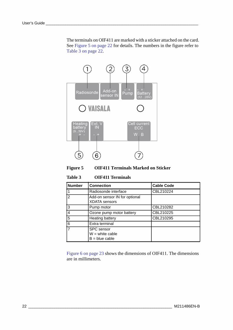
The terminals on OIF411 are marked with a sticker attached on the card. See Figure 5 on page 22 for details. The numbers in the figure refer to Table 3 on page 22.
Figure 5 OIF411 Terminals Marked on Sticker
Figure 6 on page 23 shows the dimensions of OIF411. The dimensions are in millimeters.
Table 3 OIF411 Terminals
Number Connection Cable Code1 Radiosonde interface CBL2102242 Add-on sensor IN for optional
XDATA sensors3 Pump motor CBL2102824 Ozone pump motor battery CBL2102255 Heating battery CBL2102956 Extra terminal7 SPC sensor
W = white cableB = blue cable
22 __________________________________________________________________ M211486EN-B

Chapter 2 ______________________________________ Product and System Component Overview
1401-009Figure 6 OIF411 Dimensions
VAISALA_______________________________________________________________________ 23

User’s Guide ______________________________________________________________________
Radiosonde RS41 Additional Sensor InterfaceFigure 7 on page 24 shows details of the radiosonde additional interface connector. See also Table 4 on page 24 for details on the RS41 electrical interface and the additional sensor.
1311-203Figure 7 RS41 Additional Sensor Interface
Table 4 Electrical Interface of RS41 and the Additional Sensor
Radiosonde Additional SensorPin Name I/O Function Pin Name1 GND - Ground Common2 RxD I Serial data from the
additional sensorInstrument Serial OUT
3 TxD O Serial data to the additional sensor
Instrument Serial IN
4 ... 10 Reserved For Vaisala use only Do not connect
24 __________________________________________________________________ M211486EN-B
Chapter 2 ______________________________________ Product and System Component Overview
Equipment and Material NeededSeveral items are needed to prepare the ozone sensor and the radiosonde for a flight. The items listed below are included in the Vaisala Ozone Sounding Startup Kit and they are explained in more detail in the sections below:
- Ozonizer/Test Unit TSC-1 (or similar, from other manufacturers)
- Ozone destruction filter
- Pump test unit
- Laboratory ware set
- Ozone chemicals
- Air flow meter
These items are valid when using the SPC ECC-6A ozone sensor or Droplet Measurement Technologies Model Z ozone sensor. Some sensor manufacturers also have their own startup kits. Note that these kits may not necessarily include all the required items for conducting an ozone sounding. For more details, refer to the sensor manufacturers’ manuals.
VAISALA_______________________________________________________________________ 25

User’s Guide ______________________________________________________________________
Vaisala Ozone Sounding Startup KitVaisala part number 25820OS.
Vaisala Ozone Sounding Startup Kit is used when preparing a new ozone sounding site. The kit includes materials and equipment for the sounding preparations. A list of the items and their part numbers are provided in Table 5 on page 26. More detailed information is given in the sections below.
Also note the following points:
- The preparation startup kit delivered by SPC (see Operator’s Manual for Model 6A-ECC Ozonesonde) differs from the Vaisala startup kit.
- The preparation startup kit delivered by Droplet Measurement Technologies (Operator Manual for Corporation Model Z Ozonesonde, or product brochure) differs from the Vaisala startup kit.
- Triple-distilled water and some other chemicals are not delivered, as they are easily available on the local sites.
- Documentation contains several manuals. Refer to section Related Manuals on page 11 for further details.
- Instructions for using the sounding software are needed to conduct a successful sounding. In addition to the instructions in this manual, MW41 sounding software contains an embedded on-line help with instructions for performing an ozone sounding.
- The Ozonizer/Test Unit TSC-1 is traditionally used for ozone sensor preparation. However, these days it is possible to substitute
Table 5 Ozone Sounding Startup Kit
Pieces Item Vaisala Part Number1 Ozonizer/Test Unit TSC-1 127681 Ozone destruction filter 13197OS1 Pump test unit 12785OS1 Set of laboratory ware 13198OS1 Ozone chemicals 13199OS1 Air flow meter 1319OS1 Balance 127711 Power supply 127671 Ozone documentation (includes several
manuals)
26 __________________________________________________________________ M211486EN-B

Chapter 2 ______________________________________ Product and System Component Overview
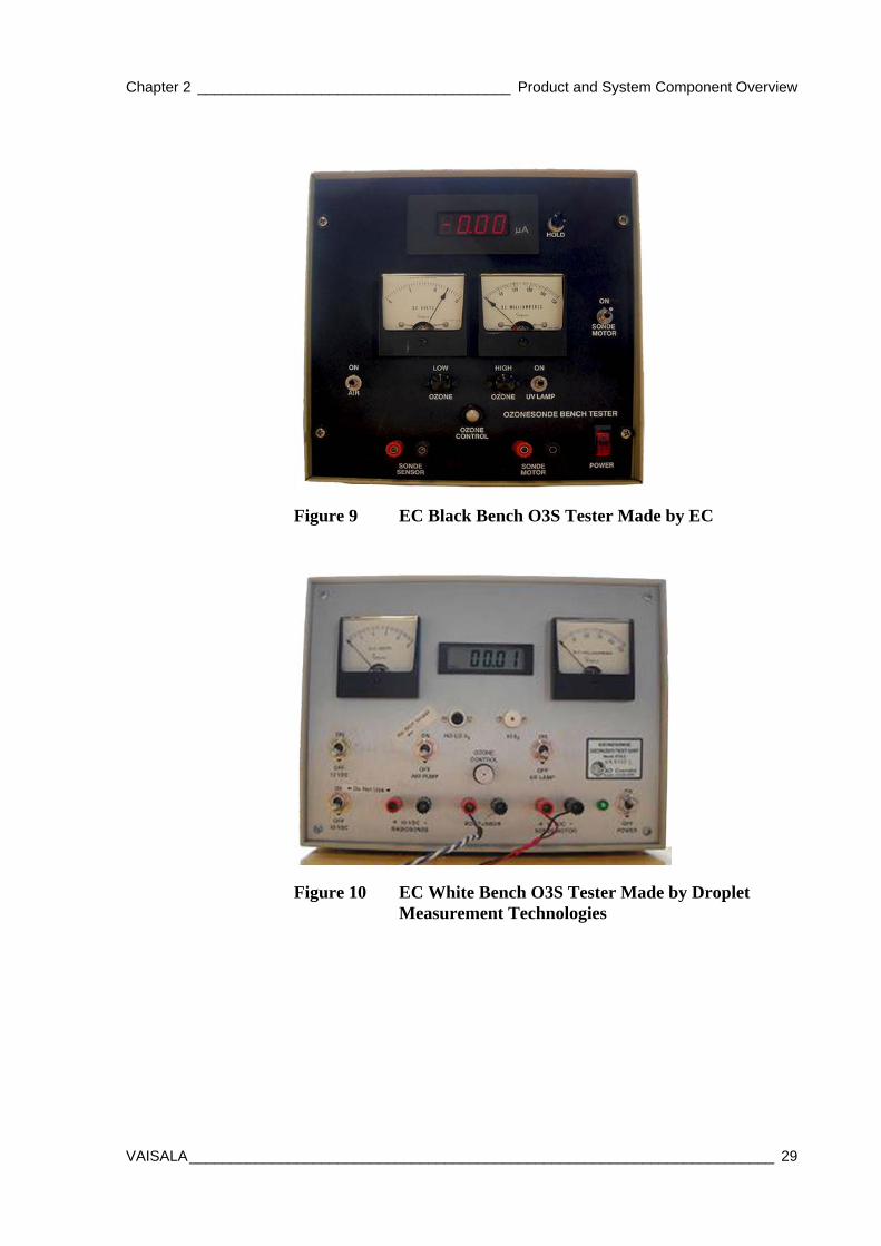
it with different models that have a digital ampere meter. A newer digital model is available from DMT (see Figure 10 on page 29 in section Ozonizer/Test Unit TSC-1 on page 27).
Ozonizer/Test Unit TSC-1This topic and Figure 8 on page 27 present the Science Pump Corporation Model TSC-1 Ozonizer/Test Unit in more detail. Other options are also available, see Figure 9 on page 29 and Figure 10 on page 29.
1006-003Figure 8 Ozonizer/Test Unit TSC-1
NOTE Vaisala recommends adding a digital ampere meter with a minimum resolution of 0.01 uA beside Ozonizer TSC-1, and checking the current from the digital ampere meter instead of the analog meter on TSC-1.
VAISALA_______________________________________________________________________ 27

User’s Guide ______________________________________________________________________
The Science Pump Corporation Model TSC-1 Ozonizer/Test Unit (or a similar equipment, see Figure 9 on page 29 and Figure 10 on page 29) is a necessary basic equipment for the preparations.
The TSC-1 Ozonizer/Test Unit model has been designed for conditioning ECC ozonesondes with the ozone, and for checking the radiosonde’s performance prior to balloon release.
The Ozonizer/Test Unit and its operation are described in more detail in the SPC Operator's Manual for Model 6A-ECC Ozonesonde and in the SPC Operator's Manual for Model TSC-1 Ozonizer/Test Unit. See Table 1 on page 11 for a list of related manuals.
The following spare parts are available for TSC-1:
- Calibrator ECC ozone sensor, OTU-15. Vaisala part number 18955.
- Internal ozone filter, OTU-17. Vaisala part number 18960.
- Other spare parts mentioned in the TSC-1 manual are also available.
NOTE For background current measurement, the ampere meter resolution must be 0.01 A. This is difficult to achieve with an analog ampere meter, thus the GAW report 201 recommends the use of a digital model.
28 __________________________________________________________________ M211486EN-B
Chapter 2 ______________________________________ Product and System Component Overview
1403-002Figure 9 EC Black Bench O3S Tester Made by EC
1403-003Figure 10 EC White Bench O3S Tester Made by Droplet Measurement Technologies
VAISALA_______________________________________________________________________ 29

User’s Guide ______________________________________________________________________
Ozone Destruction FilterThe ozone destruction filter eliminates ozone generated during testing. Table 6 on page 30 lists the parts required for the ozone destruction filter. However, the ASOPOS panel (Assessment of Standard Operating Procedures for Ozonesondes) recommends the use of purified, ozone-free air instead of the destruction filter. Refer to the GAW report 201 for more information. See Appendix D Performance Review Literature on page 119.
Assemble the ozone destruction filter components as shown in Figure 11 on page 31.
Table 6 Equipment Required for Ozone Destruction Filter
Item Required Vaisala Part Number
Particle and ozone filter: Mine Safety Appliances (MSA) Company. Delivered by MSA as a single cartridge (part number 815185).
234561 (1 pc)
Funnel, 75 mm in diameter, tube diameter 8 mm, glass 12725Connector tube 1: soft silicon tube approximately 5 cm long, inner diameter 6 mm, outer diameter 10 mm
12642OS (set of tubes)
Connector tube 2: soft vinyl tube approximately 60 cm long, I.D. 1/8" (3.2 mm), O.D. 1/4" (6.4 mm)
12642OS (set of tubes)
Connector tube 3: soft silicon tube approximately 2 cm long, inner diameter 2 mm, outer diameter 4 mm
12642OS (set of tubes)
Connector tube 4: Cut a piece of tubing from the ECC sensor air intake tube (2 cm), or order separately.
17348S (by the meter) or SPC spare part No. OTU-19
Electrical tape (Nitto 15) 4103
30 __________________________________________________________________ M211486EN-B

Chapter 2 ______________________________________ Product and System Component Overview
1006-005Figure 11 Ozone Destruction Filter
Pump Test UnitTable 7 on page 31 lists the equipment needed for the pump test unit.
The following numbers refer to Figure 11 on page 31:1 = Catalyst2 = Ultra fiber3 = Funnel4 = Connector tube 15 = Connector tube 26 = Connector tube 37 = Tape 1, 2, and 3 together with electrical tape.
Table 7 Equipment Required for Pump Test Unit
Item Required Vaisala Part Number
Vacuum/pressure gauge and connection screw. Range -1 ... 1.5 Bar, division 0.05 Bar. Includes connection parts for measurement gauge to tubing.
15240
Locking nutConnector tube 1: soft vinyl tube approximately 60 cm long, I.D. 1/8" (3.2 mm), O.D. 1/4" (6.4 mm)
12642OS (set of tubes)
Connector tube 2: soft silicon tube approximately 2 cm long, inner diameter 2 mm, outer diameter 4 mm
12642OS (set of tubes)
VAISALA_______________________________________________________________________ 31

User’s Guide ______________________________________________________________________
Set up the vacuum/pressure gauge as shown in Figure 12 on page 32.
0106-008Figure 12 Vacuum/Pressure Gauge
Set up the pump unit following the steps below:
1. Insert connector tube 1 into the locking nut (see number 3 in Figure 12 on page 32).
2. Push the tube over the tip of the connection screw on the gauge (number 1).
3. Gently tighten the locking nut over the connector tube onto the gauge (number 2).
Connection tube 3: cut a piece of tubing from EEC sensor air inlet tubes to a length of approximately 3 cm, or order separately.
17348S (by the meter) or SPC spare part No. OTU-19
The following numbers refer to Figure 12 on page 32:1 = Gauge and connection screw2 = Locking nut3 = Connector tube 14 = Connector tube 25 = Connector tube 3
Table 7 Equipment Required for Pump Test Unit (Continued)
Item Required Vaisala Part Number
32 __________________________________________________________________ M211486EN-B
Chapter 2 ______________________________________ Product and System Component Overview
4. Insert connector tube 2 (number 4) into connector tube 1 (number 3) by at least 5 mm.
5. Finally, insert the connector tube 3 (number 5) into connector tube 2 (number 4) by at least 1 cm.
Laboratory Ware SetBottles and glassware are needed, for instance, for preparing and storing sensing solutions, and for sensor cleaning. The set presented in Table 8 on page 33 is useful and can easily be obtained from any laboratory ware dealer. The set can also be ordered from Vaisala by referring to the part numbers listed in the table.
NOTE Be careful when attaching connector tube 1 to the connection screw tip. Be sure to tighten the locking nut gently to avoid damaging or tearing the connection tube. The condition of the connection tube can be checked by opening the locking nut.
Table 8 Laboratory Ware Needed
Item Pieces Vaisala Part Number
Beakers (Pyrex glass) 1 pc, volume 250 ml (subdivision 50 ml)1 pc, volume 50 ml
12721
12720Cylinder (Pyrex glass) 1 pc, volume 100 ml
(subdivision 1 ml)12722
Volumetric flasks with stoppers (Pyrex glass)
1 pc, volume 1000 ml1 pc, volume 500 ml1 pc, volume 100 ml
1272421485712723
Bottles with stoppers (preferably colored glass)
2 pcs, volume 1000 ml 2 pcs, volume 100 ml
12738 + 1274012739 + 12740
Funnels 2 pcs, mouth diameter 75 mm, pipe 10 mm, for liquids, glass1 pc, mouth diameter 65 mm, pipe 10 mm, for powder, polypropylene
12725
12726
Spatulas 3 pcs, polypropylene or steel 12729Basins (polypropylene or glass)
2 pcs, for powder weighing 12727
VAISALA_______________________________________________________________________ 33
User’s Guide ______________________________________________________________________
Ozone ChemicalsThe chemicals used must be very pure, at least of Pro Analysis quality.
Syringes with needle Disposable; total volume 3 ml, division. 0.1 ml (at least 0.5 ml). Plastic (Teflon)2 pcs, Syringe2 pcs, Syringe needle
1273612737
Thermometer 1 pc, for room temperatures HST12
Table 9 Required Ozone Chemicals
Chemical Required Amount Vaisala Part Number
KI 1 kg 12743KBr 0.5 kg 12744NaH2PO4·H2O 0.5 kg 12741Na2HPO4·12H2O (or Na2HPO4·7H2O) 0.5 kg 12742Methanol (CH3OH) -Glycerol -Acetone -
Table 8 Laboratory Ware Needed (Continued)
Item Pieces Vaisala Part Number
34 __________________________________________________________________ M211486EN-B

Chapter 2 ______________________________________ Product and System Component Overview
Air Flow MeterTable 10 on page 35 lists the equipment required for the Air Flow Meter. Section Using the Air Flow Meter on page 35 explains how the air flow meter is used in ozone sounding preparations. Figure 13 on page 37 shows an example of an air flow meter.
Using the Air Flow Meter
This procedure is meant to be carried out with no remarkable breaks (that is, breaks lasting over two hours).
Table 10 Equipment Required for Air Flow Meter
Item Required Vaisala Part Number
Air flow meter tube. Burette with filling tube, capacity 100 ml
12733
Rubber bulb, capacity approximately from 50 to 80 ml 12734Burette stand with two bossheads and two clamps 12730 (stand),
12732 (bosshead), 12728 (clamp)
Stop-watch, accuracy at least 0.1 s 12784Connector tube 1: soft silicon tube approximately 5 cm long, inner diameter 6 mm, outer diameter 10 mm
12642OS (set of tubes)
Connector tube 2: soft vinyl tube approximately 60 cm long, I.D. 1/8" (3.2 mm), O.D. 1/4" (6.4 mm)
12642OS (set of tubes)
Connector tube 3: soft silicon tube approximately 2 cm long, inner diameter 2 mm, outer diameter 4 mm
12642OS (set of tubes)
Dishwashing liquid: Add about one teaspoon of dishwashing liquid and one teaspoon of glycerol to 1 dl of water.
NOTE To avoid contamination, note the following precautions: Work in a clean environment with clean hands. Never operate the pump without the ozone destruction filter or purified air. Do not use a sensor loaded with solutions if the sensor is not connected to a powered interface (or if the anode and cathode wires are connected).
VAISALA_______________________________________________________________________ 35
User’s Guide ______________________________________________________________________
Arrange the air flow meter as shown in Figure 13 on page 37. The procedure for air flow measurement is described below. The numbers within brackets refer to the items in Figure 13 on page 37:
1. Fill the rubber bulb (4) and the flow meter tube with soap solution (8) almost up to the filling tube of the flow meter tube.
2. Connect the air flow meter to the sensor cathode air exhaust tube. This is done by slipping the connector tube 3 (9) over the short Teflon tube protruding from the top plug of the sensor cathode chamber.
3. With the radiosonde air pump operating, squeeze the rubber bulb (4) slightly to cause several soap bubbles to rise up the flow meter tube. Repeat the process several times, until the bubbles reach the top of the tube without breaking.
4. Now form only one bubble, and use a stop-watch to determine the time (t) required for the bubble to rise from 0 to 100 ml up the flow meter tube (5). Repeat the measurement three times to obtain a mean value.
NOTE When the air flow is measured, make sure the sensor is charged with the sensing solution.
36 __________________________________________________________________ M211486EN-B

Chapter 2 ______________________________________ Product and System Component Overview
1006-004Figure 13 Air Flow Rate Measurement
The following numbers refer to Figure 13 on page 37:1 = Stand2 = Bosshead3 = Connector tube 14 = Rubber bulb5 = Flow meter tube6 = Clamp7 = Connector tube 28 = Dishwashing liquid9 = Connector tube 3
VAISALA_______________________________________________________________________ 37

User’s Guide ______________________________________________________________________
Other Equipment and Material
Balance
The balance must fulfill the following requirements:
- Measurement range must be from 0 to 500 g.
- Accuracy required is 0.01 g.
Thermometer
A thermometer is needed for measuring air temperature. It can be a mercury thermometer or an electrical thermometer.
The thermometer must be capable of measuring normal room temperature, a suitable measurement range is between -2 and +50 °C. The recommended thermometer subdivision is 0.1 or 0.2 °C.
Power Supply
A power supply rated at 5 to 18 VDC, 300 mA is required for the ozone pump motor. Refer to the manufacturers’ manuals for details.
Protective Gloves
Use disposable gloves to avoid dust and other contaminants. The gloves must be lint-free and made of artificial fabric or plastic. Note that RSA411 Ozone Interface Kit does not include gloves.
38 __________________________________________________________________ M211486EN-B

Chapter 2 ______________________________________ Product and System Component Overview
Expendables and Spare PartsAfter establishing an ozone sounding site, check the availability of expendables and spare parts. Making a list of these items is recommendable. A large variety of spare parts is available from Vaisala.
The list of expendables includes at least:
- Radiosondes, interfaces
- Sounding accessories (for example, balloons)
- Ozone solution chemicals
- Syringes, needles
- Protective gloves
- Triple-distilled or ion-changed water
See also Appendix E Checklist for Equipment and Supplies for Flight Preparations on page 117.
VAISALA_______________________________________________________________________ 39

User’s Guide ______________________________________________________________________
40 __________________________________________________________________ M211486EN-B

Chapter 3 _____________________________________________ Constructing an Ozone Sounding
CHAPTER 3CONSTRUCTING AN OZONE SOUNDING
This chapter describes how to construct an ozone sounding.
Sounding Preparation Phases and SchedulePerform the preparations preferably at temperatures between +20 and +30 °C.
Preparing an ozone sounding consists of the following steps. See the sections below for more information.
- Preparations 7 to 3 Days Prior to Release on page 43.
- Preparations on the Day of Release on page 46.
- Preparations Just Before Release (2 - 0 Hours) on page 48.
WARNING The chemicals involved in an ozone sounding can be harmful, and must be handled with proper care. To ensure your working safety, take all the necessary precautions before beginning the preparations for a flight. Read the sensor manuals carefully. Follow the local laboratory work practices, regulations, and waste management guidelines. Use disposable gloves to avoid dust and other contaminants. The gloves must be lint-free and made of artificial fabric or plastic. RSA411 Ozone Interface Kit does not include gloves.
VAISALA_______________________________________________________________________ 41

User’s Guide ______________________________________________________________________
The ASOPOS panel recommends recording three different background currents:
- IB0: after 10 minutes of ozone-free air before exposure of ozone.
- IB1: after 10 minutes of ozone-free air after exposure of ozone (5 A ozone equivalent of 170 - 180 ppbv).
- IB2: at launch site after 10 minutes of ozone-free air.
NOTE The ASOPOS panel recommends using the following as sensing solutions:
SPC6A: 1.0%, KI, full buffer (STT1.0)
DTM: 0.5% KI, half buffer (SST0.5)
The recommendation is only meant for new ozone sounding stations. The existing stations that perform long-term measurements must not change their sensing solution type or ECC type.
NOTE IB2 equals to Vaisala IBG = I0, used in Vaisala scripts.
42 __________________________________________________________________ M211486EN-B

Chapter 3 _____________________________________________ Constructing an Ozone Sounding
Preparations 7 to 3 Days Prior to ReleaseThis phase consists of checking the overall performance of the ozone sensor, and charging the sensor with the sensing solution. A Model TSC-1 Ozonizer/Test Unit is used to check the overall sensor performance.
The purpose of these preparations is to make sure that the ozone sensor functions properly and can be used in an ozone sounding.
The limit values mentioned here are valid only for SPC ECC-6A ozone sensor. For other ozone sensors, create and use a modified checklist.
Preparation StepsTo enable smooth operation, place all the necessary parts on a table, but leave some free space in front of the ozonizer, if necessary.
1. Write down the following information:
Date: _______ Station: _________ Operator: __________
2. Check the label on the flight box and record the information here.
Ozone sensor number:
Manufacturer:
Date of manufacture:
Pump pressure:____________ in Hg
WARNING The chemicals involved in an ozone sounding can be harmful, and must be handled with proper care. To ensure your working safety, take all the necessary precautions before beginning the preparations for a flight. Read the sensor manuals carefully. Follow the local laboratory work practices, regulations, and waste management guidelines. Use disposable gloves to avoid dust and other contaminants. The gloves must be lint-free and made of artificial fabric or plastic. RSA411 Ozone Interface Kit does not include gloves.
NOTE Make sure to perform the initial preparations early enough, from 1 week to 3 days before the ozone sounding release. This must be done to attain a low sensor background current and a fast sensor response to ozone.
VAISALA_______________________________________________________________________ 43

User’s Guide ______________________________________________________________________
Pump voltage:____________ V DC
Pump current:____________ mA
Flow rate:_____________s/100 ml
3. Connect the ozone sensor to the ozonizer (motor, output, sensor leads).
a. Turn on the ozonizer.
b. Record IB0 before applying any ozone to the sensor:
IB0_____________A
4. Condition the pump and the dry sensor with HI O3 for 30 minutes.
5. After 10 minutes of HI O3, check the following values from the ozonizer:
(Normal head pressure and vacuum values are 700 ... 900 hPa)
6. Turn off HI O3. Run NO O3 for 5 minutes.
7. Next, you must charge sensor cathode and anode. Use a different syringe for cathode and anode.
Charge sensor cathode with solution 3.0 cm3 and wait 2 minutes.
Charge sensor anode with solution 1.5 cm3.
8. The current starts to decrease. Sensor background current after 10 minutes (typically the value is under 1.5 A) on NO O3: ____________A
9. Run on moderate ozone (about 5 A) for 10 minutes.
Measured Limit valuesPump voltage
_________ V 12 ... 13 V
Pump current
_________ mA SPC: < 115 mA; DTM: <100 mA
Head pressure
_________ Pa 670 hPa app. 20 in Hg
Vacuum (this is a minus value)
_________ Pa 670 hPa app. 20 in Hg
44 __________________________________________________________________ M211486EN-B

Chapter 3 _____________________________________________ Constructing an Ozone Sounding
10. Check the sensor response to LO O3. It should be about 5 A.
11. Run on NO O3 for 10 minutes. Record the background current: IB1____________A
12. Switch everything off and short-circuit the ozone sensor wires.
13. Put the ozone sensor back to the flight box and store it in a dark, clean-air environment at a temperature of 20 ... 25 °C until it is used.
After these preparations, a sensor cleaning process takes place, whereby both half cells (anode and cathode) and ionbridge get in balance.
VAISALA_______________________________________________________________________ 45
User’s Guide ______________________________________________________________________
Preparations on the Day of Release
Preparation Steps
1. Write down the following information:
Date: ________ Station:_________ Operator: __________
Ozonesonde number: _______________
Manufacturer: _______________
Date of manufacture: _______________
2. Run the ozone sensor motor for 5 minutes on NO O3 (optional).
3. Change cathode solution in SONDE (S) and CAL (calibrator, C; with TSC-1 only) sensors:
S: _______ ml
C: _______ml
The ASOPOS panel recommends the following:
a. Dump both solutions carefully (cathode and anode).
b. Recharge cathode cell with 3.0 cm3 cathode solution.
c. Recharge anode cell with 1.5 cm3 anode solution.
4. Condition SONDE (S) and CAL (C; with TSC-1 only.) NO O3 for 10 minutes.
5. Sensor’s background currents (< 0.2 A. ASOPOS recommendation 0.05 A):ibc = _______ Aibs= ________ A (<0.05 A; defined as IB0 by ASOPOS)
NOTE The CAL measurements are applicable when SPC’s TSC-1 Ozonizer/Test unit is used. They can be ignored with DMT’s ozonizer.
46 __________________________________________________________________ M211486EN-B

Chapter 3 _____________________________________________ Constructing an Ozone Sounding
6. Condition SONDE and CAL (with TSC-1 only) sensors with 50.2 A O3 for 5 minutes.
Measure:
SONDE sensor air flow rate:
ts =________ , ________ , ________ , ________ , ________ s
CAL sensor air flow rate:
tc =________ , ________, ________ , ________ , ________ s
Troom = ______°C; Proom =______ hPa; RHroom = ______%
7. After 5 minutes of conditioning with about 5 A O3:
ic = A ________ is = A________
With NO O3, check the sensor response test, 30 seconds:
i0.51c: = ________μA i0.5s: μA ________0.5 minute
i1c: = ________A i1s: A ________1 minute
i2c: = ________A i2s: A _______ 3 minutes
i3c: = ________A i3s: A _______ 5 minutes
i10c: = ________A i10s: A ______ 10 minutes (equals to IB1)
Record cell current at t = 0, 0.5, 1, 3, 5, and 10 minutes (as recommended by ASOPOS i10s = IB1 background current).
Computed for calibration acceptance check out:
(ic-ibc) tc = ________ (is-ibs) ts = ______ (agree to within 5%. If necessary, take corrective action to get the desired result. See Science Pump Corporation’s Operator’s Manual for further instructions.)
i1c = ________ <0.20 (ic-ibc)______
i1s = ________ <0.20 (is-ibs)______
or, alternatively with DMT ozonizer:
i1s = _______ <0.20 (is-IB1)
VAISALA_______________________________________________________________________ 47

User’s Guide ______________________________________________________________________
Preparations Just Before Release (2 - 0 Hours)These preparations must be performed from 2 to 0 hours before the sounding balloon release. Table 11 on page 48 presents the workflow included in preparing the radiosonde and OIF411 for a sounding with sounding software MW41 45 minutes before the launch. The steps below provide more detailed information on the preparations.
Table 11 Workflow for Ozone Sounding Preparations 45 Minutes Before Launch
Time to Launch in Minutes
Ozone Sensor Interface OIF411
Radiosonde RS41
Sounding Software MW41
Balloon and Accessories
45 Select battery type and any supplemental heat source needed, based on the previous flight’s performance.
Attach interface board to pump frame.
Attach radiosonde holder to styrofoam flight box.
Start MW41 software.
Fill the balloon and attach the detainer/unwinder/parachute.
30 Start running the ECC on ozone-free air using an external power supply for the pump motor.
Activate and condition radiosonde.
Configure software for the ozone flight.
20 Record background current.
Connect interface to RS41.
Record background current.
15 Connect battery to ozone sensor pump (activate battery if needed), and heater battery, if required.
Attach radiosonde to the flight box.
Prepare the radiosonde for flight. Put ECC into to flight box if it is not there yet (for prewarming in cold weather flights).
10 Take the ozonesonde construction outside to acclimatize and record surface ozone.
Check telemetry data.
Attach radiosonde to the balloon.
0 Check telemetry data.
Release the balloon.
48 __________________________________________________________________ M211486EN-B

Chapter 3 _____________________________________________ Constructing an Ozone Sounding
Starting Preparations1. Write down the following information:
Date: ________ Station :_________ Operator: __________
Ozonesonde number: _______________
Manufacturer: _______________
Date of manufacture: _______________
Radiosonde serial number: _______________
OIF411 serial number: _______________
Attaching Radiosonde Holder to Flight BoxEquipment and tools needed:
- A pen for marking the positions of the holder screws.
- A screwdriver for tightening the screws.
- Radiosonde holder with three plastic dowels and three screws, included in Ozone Interface Kit RSA411.
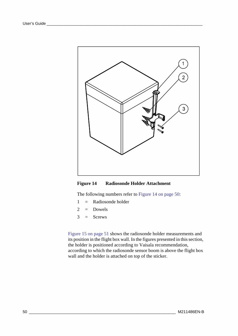
Figure 14 on page 50 shows how the radiosonde holder is attached to the flight box wall. See also the steps below.
VAISALA_______________________________________________________________________ 49
User’s Guide ______________________________________________________________________
Figure 14 Radiosonde Holder Attachment
Figure 15 on page 51 shows the radiosonde holder measurements and its position in the flight box wall. In the figures presented in this section, the holder is positioned according to Vaisala recommendation, according to which the radiosonde sensor boom is above the flight box wall and the holder is attached on top of the sticker.
The following numbers refer to Figure 14 on page 50:1 = Radiosonde holder2 = Dowels3 = Screws
50 __________________________________________________________________ M211486EN-B

Chapter 3 _____________________________________________ Constructing an Ozone Sounding
1402-102Figure 15 Radiosonde Holder Measurements (a) and Position (b)
VAISALA_______________________________________________________________________ 51

User’s Guide ______________________________________________________________________
1. The holder is attached on top of the sticker on the flight box wall. Press the radiosonde holder against the flight box wall and mark the holder screw positions with a pen.
1403-167Figure 16 Marking the Positions of the Holder Screws
52 __________________________________________________________________ M211486EN-B

Chapter 3 _____________________________________________ Constructing an Ozone Sounding
2. Use a screwdriver to insert the dowels where the holder screw marks are. Use the three dowels included in the RSA411 kit.
1403-168Figure 17 Inserting the Dowels
3. Remove the tape cover before attaching the holder. The tape makes the radiosonde holder attachment extra secure.
4. Hold the radiosonde holder against the tape and use a screwdriver to attach it to the box wall with the screws provided in the RSA411 kit.
Attaching OIF411 to SPC’s Ozone Sensor FrameFigure 18 on page 54 shows how OIF411 is attached to Science Pump Corporation’s (SPC) Model ECC-6A ozone sensor frame. See also the steps below. You do not need any extra equipment to attach OIF411 to the ozone sensor frame, the wing nuts needed are included in OIF411.
For instructions on attaching OIF411 to Droplet Measurements Technologies (DMT) Model Z ozone sensor frame, see section Attaching OIF411 to DMT’s Ozone Sensor Frame on page 56.
VAISALA_______________________________________________________________________ 53

User’s Guide ______________________________________________________________________
Figure 18 Attaching OIF411 to Ozone Sensor
To connect the ozone sensor frame and Ozone Interface Board OIF411:
1. OIF411 is equipped with two wing nuts at the back. Attach OIF411 to the ozone sensor with the wing nuts. See Figure 19 on page 55 for an illustration.
CAUTION Keep the sensor in an upright position. The sensor contains liquid.
The following numbers refer to Figure 18 on page 54:1 = Wing nuts2 = Ozone sensor frame3 = OIF411
54 __________________________________________________________________ M211486EN-B

Chapter 3 _____________________________________________ Constructing an Ozone Sounding
1310-101Figure 19 Wing Nuts on the Back of OIF411
1310-102Figure 20 OIF411 Being Attached to the Ozone Sensor Frame
VAISALA_______________________________________________________________________ 55

User’s Guide ______________________________________________________________________
2. Tighten the wing nuts.
Figure 21 OIF411 Wing Nuts Tightened
Attaching OIF411 to DMT’s Ozone Sensor FrameFor instructions on attaching OIF411 to Droplet Measurements Technologies’ (DMT) ozone sensor frame, see the steps below. In addition to OIF411 and the ozone sensor frame, you need the following equipment:
- Two M3 nuts included in RSA411 Ozone Interface Kit
- Drill with applicable drill bits
- Socket wrench for M3 nuts
- Screwdriver
Figure 22 on page 57 shows Droplet Measurements Technologies Model Z ozone sensor frame.
CAUTION Keep the sensor in an upright position. The sensor contains liquid.
56 __________________________________________________________________ M211486EN-B

Chapter 3 _____________________________________________ Constructing an Ozone Sounding
1402-103Figure 22 Droplet Measurements Model Z Sensor
To connect the ozone sensor frame and Ozone Interface Board OIF411:
1. Remove the wing nuts attached to OIF411.
2. Use a drill to make the holes in the ozone sensor frame bigger.
1405-007Figure 23 Drilling the Ozone Sensor Frame Holes
3. Attach OIF411 to the ozone sensor frame with the two M3 hex nuts, a screw driver and a socket wrench. Tighten the nuts.
VAISALA_______________________________________________________________________ 57

User’s Guide ______________________________________________________________________
Figure 24 Ozone Sensor Attached to the DMT Frame with M3 Nuts
Connecting Ozone Sensor Wires to OIF411Connect the ozone sensor wires to Ozone Interface Board OIF411.
The terminals on OIF411 are marked with a sticker attached on the card. See Figure 25 on page 59 for an example. The numbers in the figure refer to Table 12 on page 59.
58 __________________________________________________________________ M211486EN-B

Chapter 3 _____________________________________________ Constructing an Ozone Sounding
Figure 25 OIF411 Terminals Marked on Sticker
Table 12 OIF411 Terminals
Number Connection Cable Code1 Radiosonde interface CBL2102242 Add-on sensor IN for optional
XDATA sensors3 Pump motor CBL2102824 Ozone pump motor battery CBL2102255 Heating battery CBL2102956 Extra terminal7 SPC sensor
W = white cableB = blue cable
VAISALA_______________________________________________________________________ 59
User’s Guide ______________________________________________________________________
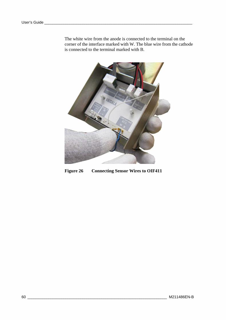
The white wire from the anode is connected to the terminal on the corner of the interface marked with W. The blue wire from the cathode is connected to the terminal marked with B.
Figure 26 Connecting Sensor Wires to OIF411
60 __________________________________________________________________ M211486EN-B

Chapter 3 _____________________________________________ Constructing an Ozone Sounding
Preparing the Radiosonde and OIF411
Connecting Ozone Sensor Pump to OIF411
- Cable needed: CBL210282
Connect the cable to the OIF411 terminal marked Pump.
Figure 27 Connecting Ozone Sensor Pump Cable
CAUTION To avoid any problems with the sounding, do not use the sensor loaded (pump-powered) with solutions, if the sensor is not connected to a powered interface, or if the anode and cathode wires are connected. The pump is allowed to be used only with NO-OZONE, or when the destruction filter is connected. Never use HI-OZONE.
VAISALA_______________________________________________________________________ 61

User’s Guide ______________________________________________________________________
Connecting Ozone Pump Battery to OIF411
- Cable needed: CBL210225
Connect the ozone pump battery to OIF411 terminal marked Battery (12 ... 20 V). At a later stage, place the battery in the empty compartment on the side of the flight box.
Figure 28 Connecting Ozone Sensor Battery Cable
62 __________________________________________________________________ M211486EN-B

Chapter 3 _____________________________________________ Constructing an Ozone Sounding
Connecting Thermistor Cable to Ozone Sensor Pump
Insert the thermistor into the hole in the pump base of the ozone sensor by pushing the thermistor hose into the hole, as shown in Figure 29 on page 63. In the SPC sensor, the hole is below the air outlet of the pump.
0901-013Figure 29 SPC ECC-6A with Thermistor Assembled
In the DMT sensor, the temperature measuring hole is on the opposite side of the pump (and is connected through the frame).
0401-221Figure 30 DMT Model Z with OIF411 Temperature Sensor Assembled
VAISALA_______________________________________________________________________ 63

User’s Guide ______________________________________________________________________
Connecting Additional Sensor Cable to OIF411
If you are using an additional sensor in the sounding, use the terminal marked Add-on sensor IN for the additional sensor cable.
Connecting Heating Battery to OIF411 (Optional)
- Cable needed: CBL210295
The heating battery is used in extreme conditions. Heating turns on automatically when the ozone pump temperature drops under +5 °C, and turns off when the temperature rises above +7 °C. There is no risk of overheating the box. However, the applicability of the heating should be checked on each site separately.
Connect the heating battery wire to the Heating battery terminal on OIF411. The red wire is connected to the terminal marked with +, and the black wire is connected to the terminal marked with -.
Figure 31 Connecting Heating Battery
64 __________________________________________________________________ M211486EN-B
Chapter 3 _____________________________________________ Constructing an Ozone Sounding
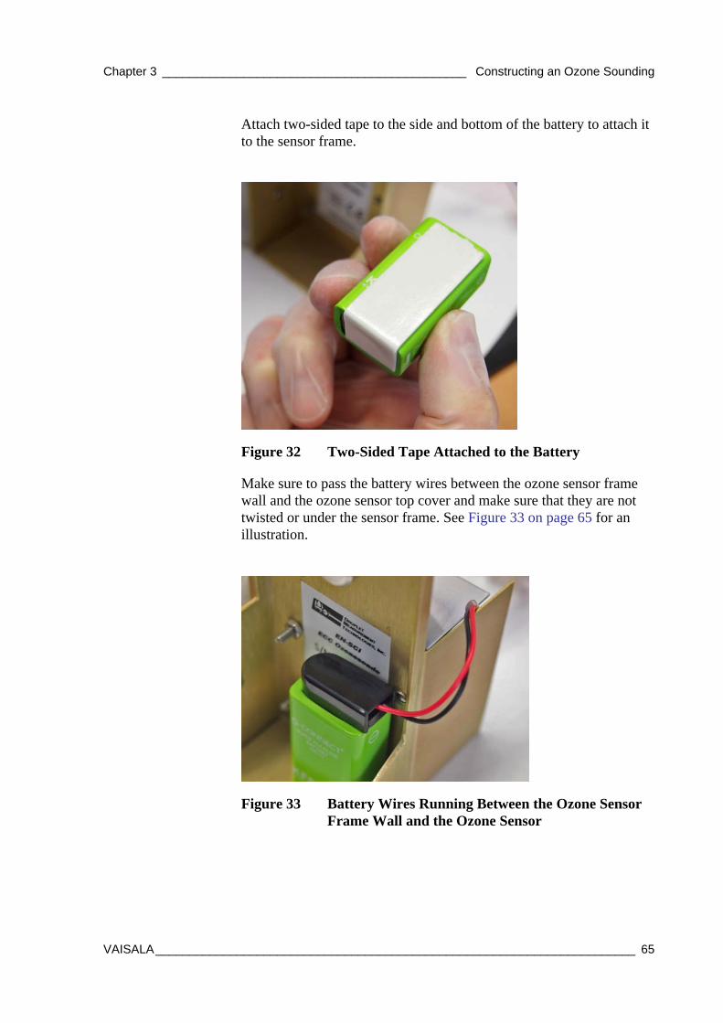
Attach two-sided tape to the side and bottom of the battery to attach it to the sensor frame.
1405-009Figure 32 Two-Sided Tape Attached to the Battery
Make sure to pass the battery wires between the ozone sensor frame wall and the ozone sensor top cover and make sure that they are not twisted or under the sensor frame. See Figure 33 on page 65 for an illustration.
1405-010Figure 33 Battery Wires Running Between the Ozone Sensor Frame Wall and the Ozone Sensor
VAISALA_______________________________________________________________________ 65

User’s Guide ______________________________________________________________________
Preparing the Radiosonde with Ground Equipment
1. Start MW41 sounding software, if you have not started it yet, and log in.
2. Attach the ozone destruction filter to the pump inlet tube.
3. Place the RS41 radiosonde on the ground check device. The radiosonde is switched on when you place it on the ground check device. The message "Preparation in progress" will be displayed in MW41.
4. Before the preparation phase is completed, scroll the MW41 page down to the Special sensor window, and select Ozone from the drop-down list.
5. Fill in the information needed and click Apply.
During this phase, the radiosonde LED light is red, but you can ignore it. It does not indicate an error at this point.
CAUTION To be able to prepare an ozone sounding with MW41, you must import and activate the following scripts: OzoneCalculations.py, OzoneMain.py, and OIF411.py. The scripts are included on the MW41 installation DVD, in folder ScriptLibrary\CalcOzone. The ozone sounding cannot be completed if any of these scripts is missing.
Import the scripts to the same Script Group and select OzoneMain.py as the main script. Make sure that Script group is set active. You do not need to set a command line argument. For more instructions, see MW41 on-line help.
CAUTION Do not connect the Ozone Interface Board OIF411 to the radiosonde while the radiosonde is placed on the ground check device. Connecting OIF411 during the ground check will interrupt the preparations and MW41 will return to the Radiosonde selection window.
NOTE The ASOPOS panel recommends 3.0 cm3 for cathode solution volume.
66 __________________________________________________________________ M211486EN-B

Chapter 3 _____________________________________________ Constructing an Ozone Sounding
1312-002Figure 34 Ozone Sensor Information
During the ground check preparations, the radiosonde status in MW41 might display an error with the message "No add-on sensor data (filtered)". You can ignore this message and proceed with the preparations, it has no effect on the ozone sounding.
1312-003Figure 35 Radiosonde Preparation in Progress
VAISALA_______________________________________________________________________ 67

User’s Guide ______________________________________________________________________
6. When the message "Waiting for background current" is displayed, remove the radiosonde from the ground check device.
1312-004Figure 36 Waiting for Background Current
7. Connect OIF411 to the radiosonde using cable CBL210224. Do as explained below:
Figure 37 Do Not Touch the Radiosonde Sensors
CAUTION Do not touch or hit the radiosonde sensors on the sensor boom. By carefully handling the radiosonde and the sensor boom, you ensure that the radiosonde functions properly during the sounding.
68 __________________________________________________________________ M211486EN-B
Chapter 3 _____________________________________________ Constructing an Ozone Sounding
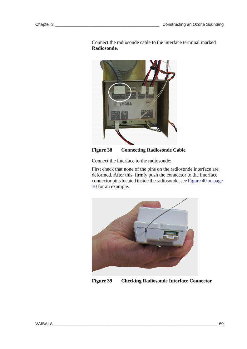
Connect the radiosonde cable to the interface terminal marked Radiosonde.
Figure 38 Connecting Radiosonde Cable
Connect the interface to the radiosonde:
First check that none of the pins on the radiosonde interface are deformed. After this, firmly push the connector to the interface connector pins located inside the radiosonde, see Figure 40 on page 70 for an example.
1310-107Figure 39 Checking Radiosonde Interface Connector
VAISALA_______________________________________________________________________ 69
User’s Guide ______________________________________________________________________
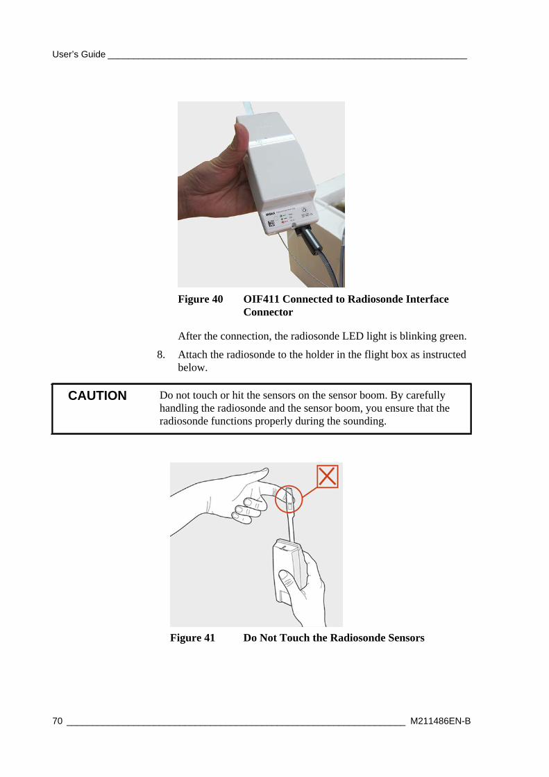
1310-105Figure 40 OIF411 Connected to Radiosonde Interface Connector
After the connection, the radiosonde LED light is blinking green.
8. Attach the radiosonde to the holder in the flight box as instructed below.
Figure 41 Do Not Touch the Radiosonde Sensors
CAUTION Do not touch or hit the sensors on the sensor boom. By carefully handling the radiosonde and the sensor boom, you ensure that the radiosonde functions properly during the sounding.
70 __________________________________________________________________ M211486EN-B

Chapter 3 _____________________________________________ Constructing an Ozone Sounding
Hold the radiosonde holder with your other hand and place the radiosonde’s bottom end to the holder first. See Figure 42 on page 71.
1403-170Figure 42 Attaching Radiosonde to the Holder
NOTE Detailed capacity information on the radiosonde battery is available in the radiosonde data sheet. OIF411 interface reduces the battery operating time by approximately 2 to 4%. If there are any delays in the sounding preparations or before the sounding starts while the radiosonde is powered from the battery, you can switch off RS41 by pressing the power switch. Switch the radiosonde back on before launching the balloon.
VAISALA_______________________________________________________________________ 71

User’s Guide ______________________________________________________________________
Use your finger to push the top part of the holder against the radiosonde so that the radiosonde is tightly attached to the holder.
403-171Figure 43 Pushing the Holder into Place
1403-172Figure 44 Radiosonde RS41 Attached to the Holder
If you attach the radiosonde in a lower position than shown here, push the holder against the flight box wall.
72 __________________________________________________________________ M211486EN-B

Chapter 3 _____________________________________________ Constructing an Ozone Sounding
9. After attaching the radiosonde, place the ozone sensor into the flight box. In this step, item a. below explains inserting SPC ozone sensor to the flight box. See item b. for DMT sensor instructions.
a. For an example of the SPC sensor inside the flight box, see Figure 45 on page 73. Make sure that the wires and tubes are led through the grooves in the flight box, indicated with the numbers in the figure.
1403Figure 45 SPC Ozone Sensor inside the Flight Box
b. For an example of the DMT sensor inside the flight box, see Figure 46 on page 74. Make sure that the wires and tubes are led through the grooves in the flight box.
The following numbers refer to Figure 45 on page 73:1 = Ozone sensor placed inside the flight box2 = Pump motor battery wires led through the groove3 = Air tube led through the groove
VAISALA_______________________________________________________________________ 73
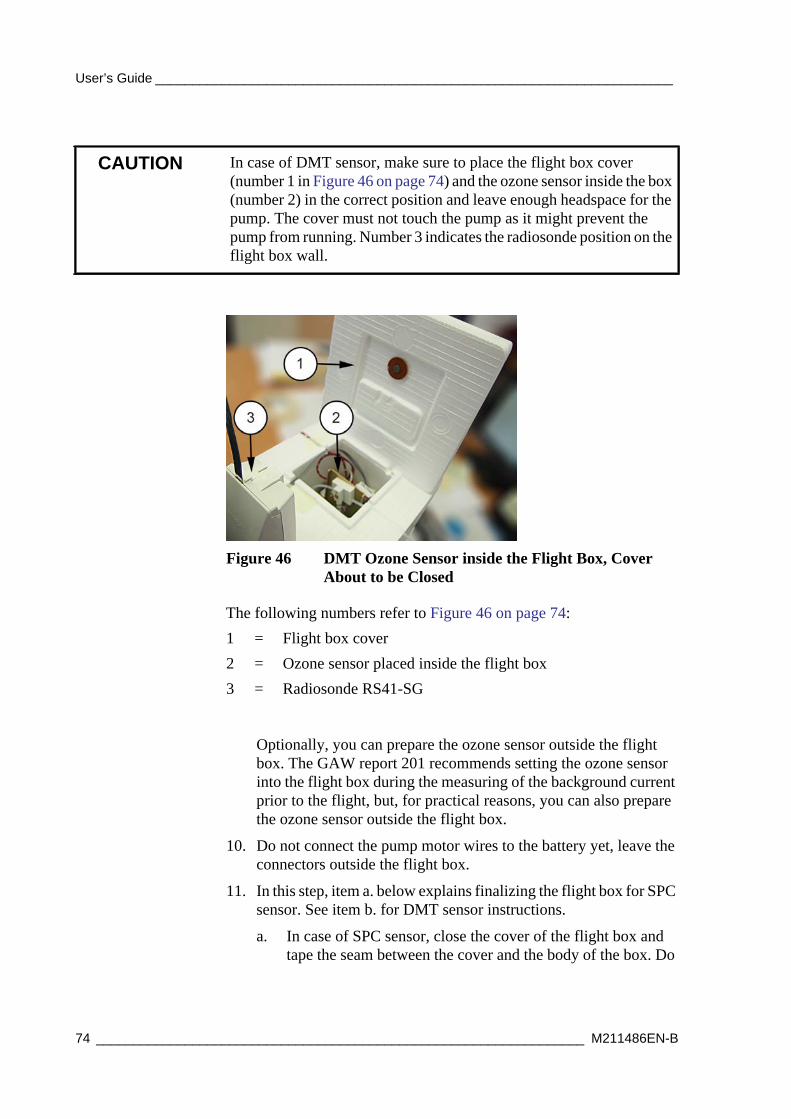
User’s Guide ______________________________________________________________________
Figure 46 DMT Ozone Sensor inside the Flight Box, Cover About to be Closed
Optionally, you can prepare the ozone sensor outside the flight box. The GAW report 201 recommends setting the ozone sensor into the flight box during the measuring of the background current prior to the flight, but, for practical reasons, you can also prepare the ozone sensor outside the flight box.
10. Do not connect the pump motor wires to the battery yet, leave the connectors outside the flight box.
11. In this step, item a. below explains finalizing the flight box for SPC sensor. See item b. for DMT sensor instructions.
a. In case of SPC sensor, close the cover of the flight box and tape the seam between the cover and the body of the box. Do
CAUTION In case of DMT sensor, make sure to place the flight box cover (number 1 in Figure 46 on page 74) and the ozone sensor inside the box (number 2) in the correct position and leave enough headspace for the pump. The cover must not touch the pump as it might prevent the pump from running. Number 3 indicates the radiosonde position on the flight box wall.
The following numbers refer to Figure 46 on page 74:1 = Flight box cover2 = Ozone sensor placed inside the flight box3 = Radiosonde RS41-SG
74 __________________________________________________________________ M211486EN-B

Chapter 3 _____________________________________________ Constructing an Ozone Sounding
not tape the hanging strings. See Figure 54 on page 81 for an example.
Figure 47 Air Outlet Hole and Air IntakeTube Not Taped Over
NOTE Do not tape over the air outlet and air intake tube, as the measuring gas must be allowed to move in and out of the sensor box. See Figure 47 on page 75 for an illustration.
VAISALA_______________________________________________________________________ 75

User’s Guide ______________________________________________________________________
b. In case of DMT sensor, it is a good idea to attach the flight box string with another string in two places (indicated with the arrows in Figure 47 on page 75) so that the string does not hit the radiosonde sensor boom during the flight.
1405-012Figure 48 Supported Flight Box String in DMT Ozone Sensor Flight Box
12. With ozone destruction filter on or zero ozone gas for sensor background current values, run the ozone sensor for 10 minutes and record the cell current IB2:
Record IB2: ________A
NOTE The IB2 value equals to Vaisala IBG = I0, used in Vaisala scripts.
NOTE Background current is measured after the flight box is closed: Close the cover of the flight box and tape the seam between the cover and the body of the box. Do not tape the hanging strings. Do not tape over the air outlet and air intake tube, as the measuring gas must be allowed to move in and out of the sensor box. See Figure 54 on page 81 and Figure 47 on page 75.
76 __________________________________________________________________ M211486EN-B
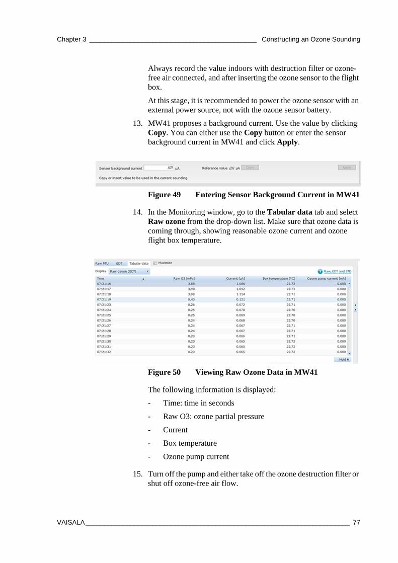
Chapter 3 _____________________________________________ Constructing an Ozone Sounding
Always record the value indoors with destruction filter or ozone-free air connected, and after inserting the ozone sensor to the flight box.
At this stage, it is recommended to power the ozone sensor with an external power source, not with the ozone sensor battery.
13. MW41 proposes a background current. Use the value by clicking Copy. You can either use the Copy button or enter the sensor background current in MW41 and click Apply.
1403-192Figure 49 Entering Sensor Background Current in MW41
14. In the Monitoring window, go to the Tabular data tab and select Raw ozone from the drop-down list. Make sure that ozone data is coming through, showing reasonable ozone current and ozone flight box temperature.
1403-169Figure 50 Viewing Raw Ozone Data in MW41
The following information is displayed:
- Time: time in seconds
- Raw O3: ozone partial pressure
- Current
- Box temperature
- Ozone pump current
15. Turn off the pump and either take off the ozone destruction filter or shut off ozone-free air flow.
VAISALA_______________________________________________________________________ 77

User’s Guide ______________________________________________________________________
16. Before starting the flight, connect the ozone sensor pump to its power supply as instructed in section Activating Pump Motor Battery on page 80. Now, continue with section Constructing Sounding Accessories on page 78.
Constructing Sounding AccessoriesNote that different installations are used depending on the components of the sounding. Always use an unwinder. An RSU stabilizer must be used if other than Vaisala-specific Totex parachute models are used.
Before you begin, see the general instructions and various sounding accessories presented in Vaisala Guide to Sounding Preparations Technical Reference.
The sounding construction depends on the radiosonde type and if either of the following is used:
- Radar reflector
- Parachute
1. If you are using other than a Vaisala-specific Totex parachute model, or a radar reflector, connect the RSU stabilizer to the unwinder and prepare the balloon string connection. See Figure 51 on page 79 for an illustration. If neither a parachute nor a radar reflector is used, proceed to step 2.
NOTE Vaisala recommends always to use the parachute in ozone soundings.
78 __________________________________________________________________ M211486EN-B

Chapter 3 _____________________________________________ Constructing an Ozone Sounding
0901-008Figure 51 Assembly of RSU Stabilizer
2. Assemble the unwinder detainer to the radiosonde unwinder by pressing the detainer head into the radiosonde unwinder.
1006-042Figure 52 Assembly of Detainer to Unwinder
3. Continue sounding preparations by tying the flight box string to the unwinder stick.
VAISALA_______________________________________________________________________ 79

User’s Guide ______________________________________________________________________
4. If neither a parachute nor a radar reflector is used, connect the unwinder to the balloon as shown in Figure 53 on page 80. Pass the unwinder hook through the loop created by the tied balloon neck. Make sure that the hook comes out from the other side.
1206-014Figure 53 Unwinder Attached to the Balloon Neck
Activating Pump Motor Battery
1. Activate the ozone sensor battery 20 minutes prior to release, and pack the battery into the compartment in the flight box. Check telemetry.
2. Take the flight box outside and connect the free-hanging battery cable with the ozone sensor battery cable. As the pump is quite noisy, you should be able to hear the ozone sensor pump running.
NOTE When DMT Model Z ozone sensor is used, the unwinder string is firmly attached to the ring hanger.
NOTE Balance the radiosonde payload by moving the string knot on the bottom of the flight box, and secure it with a piece of tape.
NOTE Ozone sensors may also use water-activated batteries, which have their own separate activation instructions. Follow the battery manufacturers’ instructions.
80 __________________________________________________________________ M211486EN-B

Chapter 3 _____________________________________________ Constructing an Ozone Sounding
1403-174Figure 54 Taped Flight Box
NOTE Do not tape over the battery compartment, as the fumes from the battery must be allowed to move out of the box. See Figure 54 on page 81 for an example.
VAISALA_______________________________________________________________________ 81

User’s Guide ______________________________________________________________________
Recording the Surface Ozone
In the MW41 Monitoring window, go to the Tabular data tab and select Raw ozone from the drop-down list. Make sure that ozone data is coming through, showing reasonable ozone current and ozone flight box temperature.
1403-169Figure 55 Viewing Raw Ozone Data in MW41
Launching the BalloonBefore launching the balloon, check the MW41 user interface to see that ozone sensor data is received. When MW41 shows the message "Ready for release", you can launch the sounding balloon.
After the release, check that the ozone data is stable in MW41.
NOTE The ASOPOS panel recommends the following: It is important that, before the launch, the ozone sensor has sampled surface air for at least 5 minutes; 10 minutes is recommended.
82 __________________________________________________________________ M211486EN-B
Chapter 3 _____________________________________________ Constructing an Ozone Sounding
Recording Post-Launch DataAfter launching the balloon, enter the surface observation data in MW41. MW41 user interface shows the appropriate data. Use the free text field for any additional data you wish to store in the database and be available for messages.
You can also write down the information here:
Launch time:
Psurf = ________ hPa
Tsurf = ________ °C
Usurf = ________ % RH
Surface wind speed: ________m/s
Wind direction: ________
Sky condition: _________________________________________
Other information: ______________________________________
VAISALA_______________________________________________________________________ 83

User’s Guide ______________________________________________________________________
84 __________________________________________________________________ M211486EN-B
Chapter 3 _________________________________________________________ Ozone Calculation
CHAPTER 3OZONE CALCULATION
This chapter describes ozone calculation in detail.
The ozone data is combined with meteorological radiosonde data: pressure (P), temperature (T) and relative humidity (U) in the ground equipment. The measuring sample interval (measures each sensor once) of Radiosonde RS41-SG is 1 second. OIF411 is scanned in phase with the radiosonde PTU measuring sequence. Therefore, all the measured data is synchronized.
Averaging and Eliminating Irrelevant Measuring Results
Noise filtering helps to eliminate erroneous data. Errors may originate from various different phenomena, for example, from electrical spikes.
The filtering is made by calculating the median of a given number of consecutive samples. The median is the middlemost sample in the order of magnitude. This algorithm cuts all remarkably higher and lower measurement results compared with other measurement results near the measurement (in a given time window). The filtering window (the number of consecutive samples, where the median is made) is given to the ground equipment during ozone sounding preparation.
The median calculation algorithm is well-defined for odd values only: number of filtering window length (1, 3, 5, 7, ...) (number of measurement samples in the window). Therefore, the filtering window is defined in the ground equipment as the window radius; from the
VAISALA_______________________________________________________________________ 85
User’s Guide ______________________________________________________________________
middle to the last sample, or, equally, from the middle to the first sample. In other words, the window radius indicates how many samples before and after the corresponding sample will be taken with in the filtering window. The number of samples where the median is calculated is as follows (sample radius = window radius):
Filter Window Length = 2 × Window Radius + 1
The sample radius is the value given for the ground equipment. If the windows radius is defined as an Integer, the filter window is always an odd integer and the median algorithm is well-defined.
The ozone sensor response time is typically about 20 seconds, as indicated in the GAW report 201 (see Appendix D Performance Review Literature on page 119 for details). To avoid cutting real ozone values of the measurement results, the median filtering window length must be clearly shorter than the sensor’s response time. Note that the length is defined as the amount of samples. Therefore, different values for radiosondes with different sample rates must be used. A typical value for the window radius for RS41 is 4 (filtering window = 9 seconds).
The median filtering algorithm is disabled by setting the window radius to 0.
Ozone Partial Pressure CalculationThe ozone sensor operating principles are explained in detail in the sensor manufacturer manuals. To clarify the ozone calculation, the operation of the SPC ozone sensor ECC6A is explained here in brief.
Ozone Sensor Operating PrincipleThe ozone sensor used within the ozonesonde is an iodine-iodide redox electrochemical concentration cell. It is made of two bright platinum electrodes immersed in potassium iodide solutions of different concentrations, contained in separate cathode and anode chambers, fabricated from polytetrafluoroethylene (Teflon TFE resin). The chambers are linked together with an ion bridge that serves as an ion pathway and retards mixing of the cathode and anode electrolytes, thereby preserving their concentrations. Driving emf for the cell is derived from a difference of potassium iodide concentrations present in the two half cells. See Figure 56 on page 87.
86 __________________________________________________________________ M211486EN-B

Chapter 3 _________________________________________________________ Ozone Calculation
06-014Figure 56 Electrochemical Cell Construction
A chemical reaction starts as soon as ozone (in air) flows into the cathode solution. The reaction is an iodide-iodine redox reaction. The current can be measured when the switch S is closed. R is the load resistance of the circuit.
Ozone Sensor ReactionsThe cell system is shown in Figure 56 on page 87. Platinum electrodes are chemically inert, and do not take part in chemical reactions. Electrochemical reactions take place in the boundary layers of the electrodes. As soon as air that contains O3 molecules is bubbled through the cathode solution, the following total reaction occurs:
2 KI + 03 + H2O -> 2 KOH + I2 + 02
Iodine, I2, is formed and the I2 concentration of the solution starts to increase. If the external circuit is closed (switch S), reaction 1 is followed by reactions 2 and 3.
VAISALA_______________________________________________________________________ 87

User’s Guide ______________________________________________________________________
In the cathode chamber:
3 I - -> I3 - + 2 e-
In the anode chamber:
I2 + 2 e- -> 2 I -
These chemical reactions result in the following statement:
ONE O3 MOLECULE CAUSES A CURRENT OF TWO ELECTRONS
The current is measured with the OIF411 interface.
Calculation of Local Ozone ValuesThe partial pressure of the ozone is a measure for local ozone concentration. Sometimes ppmv values are used. Basic principles for this step of the calculations are given in the sensor manufacturer's manuals. See Related Manuals on page 11. As each molecule of ozone creates a current of two electrons, ozone concentration is:
NOTE The reaction occurs with all oxidants (such as NO2). The chemical reaction in sensor chambers is affected by the sensor dimensions, air bubbling rate, the total liquid volume of the sensor, and the temperature of the sensor solution. These factors introduce some basic errors and variance.
88 __________________________________________________________________ M211486EN-B

Chapter 3 _________________________________________________________ Ozone Calculation
where:
The partial pressure of ozone (P3) is:
R = 8.31451 JK-1 mol-1 (Molar gas constant)
Finally:
where
C = ozone concentration in mmol 1-1
F = 9.6485 × 10⁴ C (mol)-1 (Faraday constant)I = measured current in At = pumping time for 100 ml of air (seconds)
P3 = partial pressure of ozone in mPa
I = measured ozone current in AIBG = current caused by oxidants other than ozone (mainly O2) in
A (IBG equals to IB2).
Tp = measured airflow temperature in K from pump base.t = pumping time for 100 ml of air in secondsCef = correction due to reduced ambient pressure for pump
Cref = additional correction factor
NOTE IBG used in this manual is equal to I0 used in the Vaisala scripts, and IB2 used in the GAW report 201, and the ASOPOS panel recommendations.
P3 C R TairR
F 2 100ml------------------------------- I Tairt= =
P3 4.3087 10 4– I IBG– Tp t Cef Cref=
VAISALA_______________________________________________________________________ 89

User’s Guide ______________________________________________________________________
Background Current Correction (IBG)
Background current correction (IBG) is caused by oxidants other than ozone (mainly O2). Because the concentration of ozone without any additional oxidants needs to be measured, the background current has to be deducted from the measurement current.
The amount of oxidants (mainly oxygen) will decrease during sounding when ambient pressure decreases. The background current IBG is counted from the following equation recommended for the SPC ECC-6A sensor.
The Droplet Measurement Technologies Model Z sensor recommended correction is constant:
IBG = Io
when Io is measured just before release during sounding setup configuration.
NOTE Each ozone sensor manufacturer has their own recommendations for calculating IBG, Tp, and Cef. See Related Manuals on page 11.
I0 = Background current I0 is measured using ozone destruction filter through which air is pumped during the sounding preparation activities, just before release
P = ambient pressure in hPaP0 = ambient pressure when Io is measured in hPa ~ ground
pressureA0 = 0.00122504A1 = 0.0001241115A2 = -2.687066 × 10⁻⁸
IBGA0 A1 P A2 P2++A0 A1 P0 A2 P0
2+ +------------------------------------------------------------------ I0=
90 __________________________________________________________________ M211486EN-B

Chapter 3 _________________________________________________________ Ozone Calculation
By setting the background current Io = 0, the background current correction is disabled.
The ASOPOS panel recommends the use of a constant, pressure-independent IB2 in the basic equation to determine the ozone partial pressure throughout the entire vertical profile. Pressure-dependent background can be done by:
IO = (P/P0) x IB2
As a Vaisala equation, this is:
IBG = (P/P0) x IO
Pumping Time for 100 ml of Air (t)
The pumping time is measured during sounding preparations. The value is entered in the ground equipment during sounding preparations.
Measured Airflow Temperature (TP)
All sensors use measured values in a Vaisala application.
Pump Efficiency Correction (Cef)
The efficiency of the SPC Model 6A Ozonesonde air sampling pump decreases with altitude. Calculated ozone partial pressures must, therefore, be corrected for the efficiency loss. Correcting factors for Model 6A pumps, with ECC sensor cathodes filled with 2.5 cm3 sensing solution and 3.0 cm3 sensing solution, are shown in Table 13 on page 92, respectively. At pressure level (P) the value of Cef is calculated using linear interpolation as a function of pressure.
NOTE The ASOPOS panel recommends the use of 3.0 cm3 only.
VAISALA_______________________________________________________________________ 91

User’s Guide ______________________________________________________________________
For other sensor manufacturers, the pump correction is very similar to the SPC ozone sensor; only the table values differ.
For Model Z, use the following table:
Table 13 Ozone Partial Pressure Correction Factors
Ozone Partial Pressure Correction Factor Cef
Atmospheric pressure hPa
Sensor cathode solution volume 2.5 cm3
Sensor cathode solution volume 3.0 cm3
2.0 1.160 1.1713.0 1.124 1.1315.0 1.087 1.09210.0 1.054 1.05520.0 1.033 1.03230.0 1.024 1.02250.0 1.015 1.015100.0 1.010 1.011200.0 1.007 1.008300.0 1.005 1.006500.0 1.002 1.0041000.0 1.000 1.000
Table 14 Ozone Partial Pressure Correction Factors
P/hPa Cef
3 1.245 1.1247 1.08710 1.06615 1.04820 1.04130 1.02950 1.01870 1.013100 1.007150 1.002200 1
92 __________________________________________________________________ M211486EN-B

Chapter 3 _________________________________________________________ Ozone Calculation
Additional Correction Factor (Cref)It might be necessary to scale the ozone measurement values with an additional correction factor. For instance, if another method (such as light absorption) is usable for measuring total ozone concentration, partial pressure values can be corrected to fit the inferred total ozone value with the total ozone measurement in question.
This can be done in the ground equipment software by modifying one of the scaling calibration coefficients of the sensor. Preferably, the Pumping time for 100 ml of air is used for this correction.
tcorrected = t × Cref
Total Ozone CalculationTotal ozone is the integrated ozone in a column, extending from the bottom to the top of the atmosphere. Thus, it is the sum of the total ozone measured from the sounding and the estimated residual ozone (for example, total ozone after burst).
where
In the software used in Vaisala equipment, the results of total ozone calculation are in Dobson Units (DU).
For further information on total ozone calculation, see Chapter 3 Ozone Calculation on page 85.
= Total ozone from the sounding
= Residual total ozone
TOTALOZONE S R+=
S +
R
VAISALA_______________________________________________________________________ 93

User’s Guide ______________________________________________________________________
Total Ozone from SoundingThe total ozone from the sounding is calculated by summing up the amount of ozone in the layers between two measurement points as expressed in the equation below. When using the units indicated in the list below, the equation gives the total ozone in units of grams per square meter (g/m2).
where:
When the constants are inserted into the equation, it reduces to:
A commonly used unit for total ozone is Dobson Unit (DU = 2.687 × 10²⁰ molecules/m2). To get the result in DUs, ozone grams must first be divided by molar mass of ozone 48.00 g/mol and then multiplied by Avogadro's number 6.02217 × 10²³ molecules/mol. The result is ozone in molecules/m2. The unit relation above is used to convert this to DUs.
= 1.6571, ratio of molecular masses of ozone and air
g = 9.80665 m/s2, acceleration of gravitypi ... pi+n = Ambient pressure, [hPa]
i = Index for a measurement pointp3i ... p3i+n = Ozone partial pressure [mPa]
M3 = 48.00 g/mol, molar mass of ozone
NOTE The equation above gives the ozone in grams per square meter (g/m2).
s3g----- p3 pilndpi
3 p3i p3i l++g2
------------------------------------pipi 1+-----------ln
i
= =
3
s 0.0845 p3i p3i 1++pipi 1+-----------ln
i
=
94 __________________________________________________________________ M211486EN-B

Chapter 3 _________________________________________________________ Ozone Calculation
The following equation gives the result in DUs when the partial pressures are given in mPa and ambient pressures in hPa.
Residual Ozone (Total Ozone after Balloon Burst) After the balloon burst, the level of ozone is estimated by using the equation below with a constant mixing ratio (p3i = p3i+1 = p3END) up to ambient pressure 0 hPa. The equation changes to:
When the pressure is given in hPa, the equation above gives the residual total ozone in DUs.
The total ozone can now be calculated from the equation:
Another option is introduced in the GAW report 201. Post-calculation is possible, integrated ozone is reported, and residual can be calculated afterwards. It can also be changed in the script.
s 3.9449 p3i p3i 1++pipi 1+-----------ln
i
=
R3g----- p3END 7.8899 p3END=
TOTALOZONE S R+=
VAISALA_______________________________________________________________________ 95
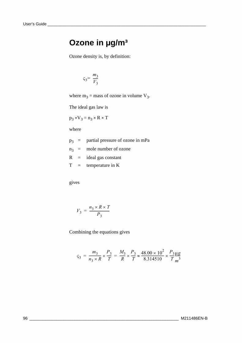
User’s Guide ______________________________________________________________________
Ozone in μg/m³Ozone density is, by definition:
where m3 = mass of ozone in volume V3.
The ideal gas law is
p3 ×V3 = n3 × R × T
where
gives
Combining the equations gives
p3 = partial pressure of ozone in mPa
n3 = mole number of ozone
R = ideal gas constantT = temperature in K
3m3V3------=
V3n3 R T
P3-------------------------=
3m3n3 R---------------
P3T------
M3R
-------P3T------ 48.00 102
8.314510----------------------------
P3T------ gm3------= =
96 __________________________________________________________________ M211486EN-B

Chapter 3 _________________________________________________________ Ozone Calculation
where:
This means that for ozone:
Accuracy of Ozonesonde MeasurementCertain sources of inaccuracy must be kept in mind when considering errors in ozone measurements. Errors can originate from the ozone sensor cell, the interface (converter), temperature and flow rate measurement, telemetry, or they can be random errors. The measurement procedure affects the accuracy. For example, if you measure only ozone partial pressure, you can do measurements in a way which is slightly different from the method you use when calculating total ozone in the end. It is also possible to improve measurement accuracy by developing the measurement methods in the sensing system.
Basic sources for errors and differences between measurement systems (the ECC system, light absorption measurement) are quite well known. Relevant literature is also available. See Appendix D Performance Review Literature on page 119.
M3 = Molar mass of ozone, 48.00 g/mol
P3 = Ozone partial pressure in mPa
T = Temperature in K
NOTE The latest detailed technical data for the radiosonde and OIF411 can be found on the Vaisala website, www.vaisala.com.
NOTE Detailed specifications for the ozone sensors are available directly from the manufacturers or from Vaisala.
1mPa 10 48.00 102
8.314510---------------------------------------- 1
T--- gm3------ 5773.04 1
T--- gm3------
VAISALA_______________________________________________________________________ 97

User’s Guide ______________________________________________________________________
98 __________________________________________________________________ M211486EN-B

Chapter 4 ___________________________________________ Ozone Interface Board OIF411 Data
CHAPTER 4OZONE INTERFACE BOARD OIF411 DATA
This chapter explains the data received from Ozone Interface Board OIF411, and how it is interpreted.
Interpreting OIF411 Data
Measurement DataWhen Radiosonde RS41 is connected to Ozone Interface Board OIF411, it sends the OIF411 measurement data through the additional sensor interface. The following information is contained:
- Instrument type and number
- Ozone pump temperature
- Ozone current
- Battery voltage
- Ozone pump current
- External voltage measured once per second
OIF411 measurement data contains the following information:
VAISALA_______________________________________________________________________ 99

User’s Guide ______________________________________________________________________
xdata= <Instrument type is 05><Instrument number is 01><Ozone pump T [0.01 ºC]><Ozone current [0.0001uA]><Battery voltage [0.1V]> <Ozone pump current [1 mA]><Ext. voltage [0.1V]>CR
This means that if OIF411 sends
xdata=050108CA186A0750B637CR
it is interpreted as shown in Table 15 on page 100:
ID DataThe radiosonde also sends OIF411 ID data, which contains:
- Instrument type and number
- OIF411 serial number
- Diagnostics word
- Software version once per minute
OIF411 ID data replaces OIF411 measurement data, but not the additional sensor data, sent once per minute.
The OIF411 ID data contains the following information:
xdata= <Instrument type is 05><Instrument number is 01><OIF serial number><diagnostics word><SW version><I>CR.
This means that if OIF411 sends
xdata=0501G12345670001000AICR
Table 15 OIF411 Data Interpretation 1
Instrument Type2 Bytes
Instrument Number2 Bytes
Ozone Pump T [0.01 ºC] 4 Bytes.MSB bit is a sign bit.
Ozone Current [0.0001uA] 5 Bytes
Battery Voltage [0.1V]2 Bytes
Ozone Pump Current [1 mA]3 Bytes
Ext. Voltage [0.1 V]2 Bytes
Hex ASCII 05 01 08CA 186A0 75 0B6 37Interpreted as
5 1 22.50 10.0000 11.7 182 5.5
100 _________________________________________________________________ M211486EN-B

Chapter 4 ___________________________________________ Ozone Interface Board OIF411 Data
it is interpreted as shown in Table 16 on page 101:
Additional DataIf additional xdata-compatible sensor is connected to OIF411, it receives data from the additional xdata sensor, increments instrument number by 1, and sends this data immediately after receiving the CR.
Additional sensor data can be in any order (except that the OIF411 data always comes first), meaning that the instrument numbers are not in an ascending order. For example:
xdata=050108CA186A0750B637CRxdata=0203000900090009000900090009CRxdata=10021FF44487A04E0410018FLFCR xdata=0304001000100010001000100010CR
If additional sensor CFH is connected to OIF411, OIF411 sends
xdata=050108CA186A0750B637CRxdata=10021DB6BC8795200443018FLFCR
where LF = line feed, CR = carriage return.
Table 16 OIF411 Data Interpretation 2
Instrument Type2 Bytes
Instrument Number2 Bytes
OIF411 Serial Number 8 Bytes
Diagnostics Word 4 Bytes
Software Version2 Bytes
ID Data
Hex ASCII 05 01 G1234567 0001 000A IInterpreted as
5 1 G1234567 Bit0 set (=calibration not done)
0xA=10 dec -> SW version is 10/100= 0.10
IgnoreUse data length to distinguish ozone and ID data.
VAISALA______________________________________________________________________ 101

User’s Guide ______________________________________________________________________
102 _________________________________________________________________ M211486EN-B
Chapter 5 __________________________________________________ Storage and Transportation
CHAPTER 5STORAGE AND TRANSPORTATION
This chapter provides information for the transport and storage of the product.
StorageOzone Interface Kit RSA411 must be stored and used properly in accordance with applicable instructions, User’s Guide, and specifications issued by Vaisala.
Proper storage conditions must fulfill the following requirements:
Ozone Interface Kit RSA411 must be stored in a dry, ventilated indoor storage space, and within the following key environmental limits (ref. IEC 60721-3-1 class 1K2):
- Temperature +5 °C to +40 °C
- Relative humidity below 85%
VAISALA______________________________________________________________________ 103
User’s Guide ______________________________________________________________________
TransportationOzone Interface Kit RSA411 must be transported in the original shipping package. The package is designed and built to survive and protect its contents in the environmental conditions described herein with the terminology and standards per standard: IEC 60721-3-2. Transportation of OIF411 requires climatic conditions 2K2 and mechanical conditions 2M1 of this standard:
- Transportation in weather-protected conditions.
- Transportation using conventional means (car, truck, and/or aircraft), with free fall not exceeding 0.25 m in any circumstances.
- Following additional markings on packaging.
104 _________________________________________________________________ M211486EN-B

Chapter 6 _________________________________________________________ Technical Support
CHAPTER 6TECHNICAL SUPPORT
This chapter presents information about technical support.
Product ReturnsIf the product is found faulty, please follow the instructions below to speed up the process and to avoid extra costs to you.
1. Read the radiosonde warranty information.
2. Contact Vaisala technical support via e-mail or fax and request for RMA (Return Material Authorization) and shipping instructions.
3. Proceed as instructed by Vaisala technical support and provide the failure report as requested.
Technical Support
NOTE RMA must always be requested from Vaisala technical support before returning any faulty material.
For technical questions, contact the Vaisala technical support:E-mail [email protected] +358 9 8949 2790
VAISALA______________________________________________________________________ 105

User’s Guide ______________________________________________________________________
106 _________________________________________________________________ M211486EN-B

Appendix A _______________________________________________ DigiCORA MW41 Ozone Data
APPENDIX ADIGICORA MW41 OZONE DATA
This appendix explains the files containing the ozone-related data in MW41. In MW41, ozone-related data is created with the help of scripts. For further information on preparing and monitoring an ozone sounding with MW41, see the on-line help embedded in the sounding software.
Calculating Ozone Data in MW41Ozone data is calculated by the scripting engine using raw ozone and EDT data. This information, along with the calculated ozone, can be archived for further inspection, for example, simulation. The MW41 installation DVD contains script interface documentation which provides more information on using the scripts. Ozone calculation is implemented with three script files:
- OzoneMain.py
- OzoneCalculations.py
- OIF411.py
Reporting Ozone Data in MW41You can use the report template editor in MW41 to create an ASCII output of the calculated ozone data. The data may also be programmatically accessed via the script interface during the sounding. The ozone-related data can be exported in the following files:
VAISALA______________________________________________________________________ 107
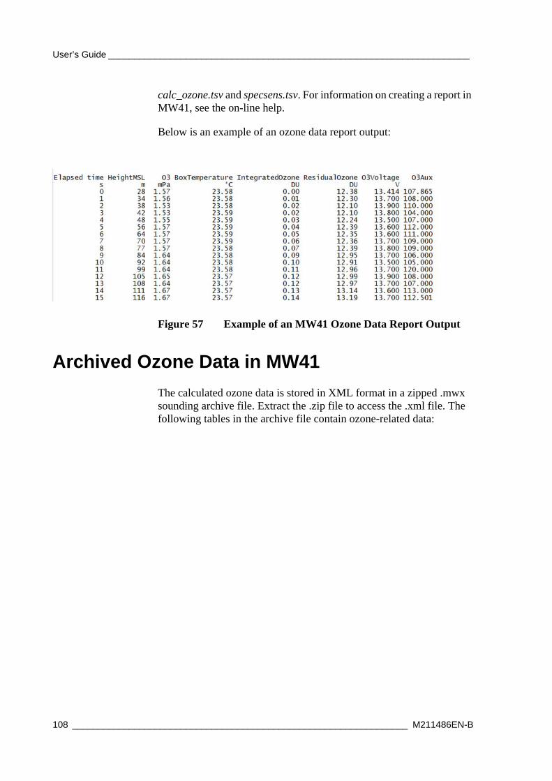
User’s Guide ______________________________________________________________________
calc_ozone.tsv and specsens.tsv. For information on creating a report in MW41, see the on-line help.
Below is an example of an ozone data report output:
Figure 57 Example of an MW41 Ozone Data Report Output
Archived Ozone Data in MW41The calculated ozone data is stored in XML format in a zipped .mwx sounding archive file. Extract the .zip file to access the .xml file. The following tables in the archive file contain ozone-related data:
108 _________________________________________________________________ M211486EN-B

Appendix A _______________________________________________ DigiCORA MW41 Ozone Data
Additional Sensor Data from RS41
Additional Sensor Data from RS92
Table 17 AdditionalSensorData
Column Name Type DescriptionSOUNDINGIDPK String Unique sounding IDRADIORXTIMEPK Double Radio time [s]INSTRUMENTTYPEPK String Instrument type identifierINSTRUMENTNUMBERPK String Instrument numberMEASUREMENTOFFSET Double Measurement time offset
of the additional sensor data [s]
DATASRVTIME String Data server timestamp [yyyy-MM-dd HH:mm:ss.fff]
GPSTIMEOFFSET Byte Offset to the frame’s GPS time [1/20 s]
XDATA String XData from additional sensor
Table 18 RS92SpecialSensorData
Column Name Type DescriptionSOUNDINGIDPK String Unique sounding IDRADIORXTIMEPK Double Radio time [s]DATASRVTIME String Data server [yyyy-MM-dd
HH:mm:ss.fff]HEADERDATA UShort Interface and sensor typeSENSORDATA String Sensor data
VAISALA______________________________________________________________________ 109

User’s Guide ______________________________________________________________________
Calculated Ozone Data Ozone layer data with pressure correction is applied.
OIF411 or OIF92 Ozone Parameters
Table 19 CalculatedOzone
Column Name Type DescriptionSOUNDINGIDPK String Unique sounding IDRADIORXTIMEPK Double Radio time [s]DATASRVTIME String Data server [yyyy-MM-dd
HH:mm:ss.fff]PARTIALPRESSURE Double Calculated ozone partial
pressure [mPa]BOXTEMPERATURE Double Sensor box temperature
[Kelvin]O3CURRENT Double Bias and pressure
corrected current [uA]INTEGRATEDOZONE Double Ozone accumulated up to
the current sounding level [DU] (Dobson Unit)
RESIDUALOZONE Double Estimated residual ozone above the current sounding level [DU] (Dobson Unit)
VOLTAGE Double OIF92: Channel 3 data OIF411: Battery voltage measurement [V]
AUX Double OIF411: ozone pump current valueOIF92: channel 4 data
Table 20 OIF411Parameters/ OIF92Parameters
Column Name Type DescriptionSOUNDINGIDPK String Unique sounding IDDATASRVTIME String Data server [yyyy-MM-dd
HH:mm:ss.fff]SENSORTYPE String Sensor type codeSERIALNUMBER String OIF411: null
OIF92: serial numberCALIBRATIONPRESSURE Double Applied calibration
pressure [hPa]SOLUTIONVOLUME Double Cathode solution volume
[cm3]
110 _________________________________________________________________ M211486EN-B

Appendix A _______________________________________________ DigiCORA MW41 Ozone Data
MEDIANFWRADIUS Double Median filter window radius
FLOWRATE Double Pump airflow rate [s/100 cm3]
IOFFSET Double OIF411: nullOIF92: offset correction for current measurement
IREFLIN Double OIF411: nullOIF92: Iref linear temperature coefficient [1/k]
IREFQUAD Double OIF411: nullOIF92: Iref quadratic temperature coefficient [1/K2]
IREFZEROC Double OIF411: nullOIF92: Iref at 0 C temperature [uA]
RNTC25 Double OIF411: nullOIF92: Sensor thermistor resistance at 25 C temperature [Ohm]
VREFCH3 Double OIF411: nullOIF92: Reference value for voltage channel [V]
VREFCH4 Double OIF411: nullOIF92: Reference value for AUX channel [V]
BGCURRENT Double Sensor background current [uA]
Table 20 OIF411Parameters/ OIF92Parameters (Continued)
Column Name Type Description
VAISALA______________________________________________________________________ 111

User’s Guide ______________________________________________________________________
Ozone ResultsSummary of calculated ozone data.
Table 21 OzoneResults
Column Name Type DescriptionSOUNDINGIDPK String Unique sounding IDDATASRVTIME String Data server [yyyy-MM-dd
HH:mm:ss.fff]INTEGRATEDOZONE Double Ozone accumulated up to
the sounding termination [DU] (Dobson Unit)
RESIDUALOZONE Double Estimated residual ozone above the termination level [DU] (Dobson Unit)
SENSORTYPE String Sensor type codeINTERFACETYPE String Ozone interface type
(Undefined, OIF411, or OIF92)
SERIALNUMBER String OIF serial numberDIAGNOSTIC Int OIF411: diagnostic word
OIF92: 0BGCURRENTCORRMETHOD
String Background current correction method
SMOOTHINGMETHOD String OIF411: nullOIF92: method for smoothing measured data
CALIBRATIONPRESSURE Double Applied calibration pressure [hPa]
BGCURRENT Double Sensor background current [uA]
SOLUTIONVOLUME Double Cathode solution volume [cm3]
OZONEPRIORSTART Double Ozone at the surface level prior to the launch [DU] (Dobson Unit)
PRIORSTARTMEASDURATION
Double Surface ozone measurement duration [min]
112 _________________________________________________________________ M211486EN-B

Appendix A _______________________________________________ DigiCORA MW41 Ozone Data
Raw Ozone DataOzone layer data without pressure correction.
Table 22 RawOzone
Column Name Type DescriptionSOUNDINGIDPK String Unique sounding IDRADIORXTIMEPK Double Radio time [s]DATASRVTIME String Data server [yyyy-MM-dd
HH:mm:ss.fff]PARTIALPRESSURE Double Raw (uncorrected) ozone
partial pressure [mPa]INTERMEDIATE Double Intermediate data being
used in calculationCURRENT Double Current measured by
sensor [uA]BOXTEMPERATURE Double Sensor box temperature
[K]VOLTAGE Double OIF92: Channel 3 data
OIF411: Battery voltage measurement [V]
AUX Double OIF411: ozone pump current value [mA]OIF92: channel 4 data
EXTERNALVOLTAGE Double OIF411: external voltage measurement [V]OIF92: 0
VAISALA______________________________________________________________________ 113

User’s Guide ______________________________________________________________________
114 _________________________________________________________________ M211486EN-B
Appendix B ______________________________________ Safety Instructions for Balloon Operators
APPENDIX BSAFETY INSTRUCTIONS FOR BALLOON OPERATORS
This appendix contains details of safe and proper balloon preparation.
Photocopy these instructions and place the list in clear view in the balloon filling shed and in the sounding compartment.
1. No smoking or naked flame allowed.
2. If possible, avoid wearing clothing made of nylon or other synthetic fibers to prevent a build-up of static charges. Do not wear shoes with rubber soles.
3. Wear protective glasses.
4. Regularly check that the gas tube fits securely to the gas cylinder or generator nozzle and to the balloon inflation nozzle.
5. Take care to prevent a gas leak in the shed when interrupting inflation to replace a gas cylinder.
6. Never use a repaired balloon.
7. Should a leak develop in the balloon during inflation, do not let gas escape from the balloon inside the shed if possible. Instead, release the defective balloon without load. It is not advisable to deflate the balloon, even outside the shed.
8. Do not touch the balloon with bare hands except when holding it by the neck. Wear soft cotton gloves.
VAISALA______________________________________________________________________ 115
User’s Guide ______________________________________________________________________
9. Ensure that there are no pointed objects in the shed. Nails, hooks, hinges, padlocks, etc., are dangerous as they might scratch the inflated balloon. The balloon film is only 0.05 ... 0.1 mm thick upon launch; the slightest scratch could cause the balloon to burst prematurely.
10. Keep the doors of the shed shut while inflating the balloon on a windy day. However, ensure that the shed is properly ventilated.
11. No unauthorized person shall be allowed admittance to the shed while the hydrogen generator is in operation or balloon inflation is going on.
12. Ensure that all tools and other implements not essential for balloon inflation have been removed from the shed.
13. Do not take any electrical devices (cell phone etc.) to the balloon filling shed or close to the balloon inflated with hydrogen. Safe distance when outdoors is typically 1.5 meters.
14. Always keep the radiosonde at least 50 cm below the level of the gas nozzle and the inflated balloon, and at least 1.5 meters away from the gas cylinder/hydrogen generator, connectors, and tubing. Avoid taking the radiosonde inside the balloon filling shed, if possible.
15. Follow all regulations concerning hydrogen safety.
WARNING New operator! Carefully study the instructions for using the hydrogen generator and for the correct method of inflation.
116 _________________________________________________________________ M211486EN-B

Appendix C _______________________ Checklist for Equipment and Supplies for Flight Preparations
APPENDIX CCHECKLIST FOR EQUIPMENT AND SUPPLIES FOR FLIGHT PREPARATIONS
This appendix contains the checklist for the equipment and supplies needed in the sounding preparations. You can mark the items in the Checked column.
Table 23 Checklist for Equipment
Equipment CheckedOzone sensor with styrofoam flight box and motor batteryRadiosonde RS41Ozone Interface Board OIF411Balloon (plastic or rubber)5 meters of string (strength about 300 to 500 N), an unwinder and a detainerParachute, 200-inch (500 cm) circumference (recommended)Short-circuit cable for the ozone sensor (optional)Ozone sensor interface - radiosonde extender test cable (optional)Bottle for the sensor cathode solution prepared according to the instructionsBottle for the sensor anode solution prepared according to the instructionsBottle for distilled H2O
VAISALA______________________________________________________________________ 117

User’s Guide ______________________________________________________________________
Syringe, 3 ml volume (equipped with Teflon tube), for use with the sensor cathode solutionSyringe, 3 ml volume, for use with the sensor anode solutionRoll of firm tape, 2 inches (5 cm) wideApparatus for measuring ozone sensor air flow rateOzonesonde power supply for pump motor rated at 12 to 13 VDC, 300 mASPC Ozonizer/Test Unit Model TSC-1 with adapter cables or equivalent from other manufacturersOzone destruction filter or purified, ozone-free gasThermometer graduated in degrees centigradeHand-held pressure/vacuum gauge for pump testsSmall strips of No. 600A sandpaper for grasping Teflon tubingPlastic squirt bottle filled with research-grade methanolMethanol and acetone for cleaningPair of lint-free gloves for laboratory work (made of artificial fabric or plastic, disposable)
Table 23 Checklist for Equipment (Continued)
Equipment Checked
118 _________________________________________________________________ M211486EN-B

Appendix D ______________________________________________ Performance Review Literature
APPENDIX DPERFORMANCE REVIEW LITERATURE
This appendix provides a list of relevant performance review literature.
Table 24 Performance Review Literature
Name DetailsAttmannspacher, W. and H.U. Dütsch
International Ozone Sonde Intercomparison at Observatory Hohenpeissenberg. Bericht des Deutschen Wetterdienstes, No. 120, 1970, 85 pp.
Attmannspacher, W and H.U. Dütsch
2nd. International Ozone Sonde Intercomparison at Observatory Hohenpeissenberg. Bericht des Deutschen Wetterdienstes, No. 157, 1981, 65 pp.
De Backer, Hugo, D. De Muer and G. De Sadelaer
Comparison of ozone profiles obtained with Brewer-Mast and Z-ECC sensors during simultaneous ascents. J. Geoph. Res., vol. 103, D16, 19641 - 19648. Johnson, B.J. , S.J. Oltmans, H. Voemel, H.G.J Smit, T. Deshler, and C. Kroeger (2002), ECC ozonesonde pump efficiency measurements and tests on the sensitivity to ozone of buffered and unbuffered ECC sensor cathode solutions. J. Geophys. Res., 107, D19 doi: 10.1029/2001JD000557. 1998.
Beekman, M. and G. Ancellet, D. Martin, C. Abonnel, G. Duverneuil and F. Eideliman, P. Bessemoulin, N. Fritz and E. Gizard
Intercomparison of tropospheric ozone profiles obtained by electrochemical sondes, a ground based lidar and an airborne UV-photemeter Atmospheric Environment Vol. 29, No. 9, pp. 1027-1042, 1995.
Brewer, A.W. and J.R. Milford The Oxford-Kew Ozonesonde, Proc. Roy. Soc A, 256, 470, 1960.
Deshler, T., Mercer, H.G.J Smit, R. Stubi, G. Levrat, B.J. Johnson, S.J. Oltmans, R. Kivi, J. Davies, A.M. Thompson, J. Witte, F.J. Schmidlin, G. Brothers, T. Sasaki
Atmospheric comparison of electrochemical cell ozonesondes from different manufacturers, and with different cathode solution strenghts: The Balloon Experiment on Standards for Ozonesondes, J. Geophys. Res., 113, D04307, doi: 10.1029/2007JD008975. Komhyr, W. D. (1969), Electrochemical concentration cells for gas analysis, Ann. Geoph., 25, 203 - 210. 2008.
VAISALA______________________________________________________________________ 119

User’s Guide ______________________________________________________________________
Godson, W.L. The representation and analysis of vertical distributions of ozone, Quarterly Journal of the Meteorological Society, Vol. 88, No. 377, July 1962.
Hoegger, B.A. & all Contribution of Switzerland to International Ozonesonde Intercomparisons. Proceedings of GAW-CH Conference Zurich, 14-15 October 1998. Swiss Agency for the Environment, Forests and Landscape (SAEFL), Environmental documentation No.110 Air, pp 43-47.
Johnson, Bryan J., Samuel J. Oltmans, H. Vomel, H.G.J. Smit, T. Deshler., and C. Kroger
Electrochemical concentration cell (ECC) ozonesonde pump efficiency measurements and tests on the sensitivity to ozone of buffered and unbuffered ECC sensor cathode solutions. J. Geophys. Res., 107 (D19), 4394, doi:1029/2001JD000557, 2002.
Kerr, J.B. & all The 1991 WMO international ozonesonde intercomparison at Vanscoy, Canada. Atmosphere Ocean, Vol XXXII, No 4 pp 685-716, December 1994.
Kley, D., H.G.J. Smit, H. Vömel, H. Grassl, V. Ramanathan, P.J. Crutzen, S. Williams, J. Meywerk, S.J. Oltmans
Tropospheric water-vapour and ozone cross-sections in a zonal plane over the equatorial Pacific Ocean, Q.J.R. Meteorol. Soc. (1997), 123, pp. 2009-2040.
Komhyr, W.D. Operations Handbook - Ozone Measurement to 40-km Altitude with 4A Electrochemical Concentration Cell (ECC) Ozonesondes (used with 1680-MHz radiosondes), NOAA Technical Memorandum ERL ARL-149,1986.
Komhyr, W.D., J.A. Lathrop, D.P. Opperman, R.A. Barns, and G.B. Brothers
ECC Ozonesonde performance evaluation during STOIC 1989, J. Geophys. Res., 100 9231-9244, 1995.
Komhyr, W.D. Electrochemical Concentration Cell for Gas Analysis Ann. Geophys., t. 25, fasc. 1, 1969, pp. 203-210.
Schenkel, A., and B. Broder Interference of some trace gases with ozone measurements by the KI method, Atmospheric Environment, 16, 2187-2190. 1982.
Schmidlin, F.J., B.A. Hoegger & all Sondex96: A Field Experiment Conducted by NASA and SMI at Payerne,Switzerland. WMO Instruments and Observing Methods Report No 70, WMO Technical Conference on Meteorological and Methods of Observation (TECO-98), Casablanca Morocco, 13-15 May 1998, (WMO/TD No. 877), pp 193-196.
Smit, H.G.J and ASOPOS panel Quality assurance and quality control for ozonesonde measurements in GAW, WMO Global Atmosphere Watch Report series, No. 121, World Meteorological Organization, Geneva, 2013.
Smit, H.G.J. Ozonesondes, in Encyclopedia of Atmospheric Sciences, edited by J. Holton, J. Pyle, and J. Curry, pp. 1469-1476, Academic Press, London. 2002.
Table 24 Performance Review Literature (Continued)
Name Details
120 _________________________________________________________________ M211486EN-B

Appendix D ______________________________________________ Performance Review Literature
Smit, H.G.J., W. Straeter, B. Johnson, S. Oltmans, J. Davies, D.W. Tarasick, B. Hoegger, R. Stubi, F. Schmidlin, T. Northam, A. Thompson, J. Witte, I. Boyd, F. Posny
Assessment of the performance of ECC-ozonesondes under quasi-flight conditions in the environmental simulation chamber: Insights from the Jülich Ozone Sonde Intercomparison Experiment (JOSIE), J. Geophys. Res., 112, D19306, doi:10.1029/2006JD007308. 2007
Smit, H.G.J. and D.Kley Jülich Ozone Sonde Intercomparison Experiment (JOSIE) ; WMO Global Atmosphere Watch report series No. 130 (Technical document No.926) WMO, Geneva, 1998.
Smit, H.G.J.& all The 1996 WMO International intercomparison of ozonesondes under quasi flight conditions in the environmental simulation chamber at Jülich, Proceedings XVIII Quadrennal Ozone Symbosium, Eds. R. Bojkov, and G. Visconti, L'Aquila, Italy, Sept. 1996.
Smit, H.G.J. & all The 1996-1999 Evaluation of Performance of ECC- Sondes Under Quasi-Flight Conditions in the Environmental Simulation Chamber, Proceedings of Quadrennal Ozone Symbosium 2000, Sapporo, Japan, July 2000. SPARC-IOC-GAW Assessment of Trends in the Vertical Distribution of Ozone (1998), SPARC Report No.1, WMO Global Ozone Research and Monitoring Project Report No. 43, World Meteorological Organization, Geneva. Note: In this report performance investigations made before 1996 have been intensively evaluated by the SPARC-IOC-GAW assessment panel
Stübi R., G. Levrat, B. Hoegger, P. Viatte, J. Staehelin, F. J. Schmidlin
In-flight comparison of Brewer-Mast and electrochemical concentration cell ozonesondes, J. Geophys. Res., 113, D13302, doi:10.1029/2007JD009091. 2008.
WMO Third WMO intercomparison of the ozonesondes used by the Global ozone observing System, Vanscoy Canada 13-24 May 1991, WMO/ Global Atmosphere Watch/WMO Global Ozone Research and Monitoring Project, Report No 27.
Table 24 Performance Review Literature (Continued)
Name Details
VAISALA______________________________________________________________________ 121

www.vaisala.com
*M211486EN*