p72606 ghz 5x/25x active probe user manual
TRANSCRIPT

xx
P72606 GHz 5X/25X Active ProbeUser Manual
*P071092203*
071-0922-03
1100111001010
11 0110011 11011
11 010100101101
001 1110110111
010101101010


P72606 GHz 5X/25X Active Probe
ZZZ
User Manual
xx
www.tektronix.com071-0922-03

Copyright © Tektronix, Inc. All rights reserved.
Tektronix products are covered by U.S. and foreign patents, issued and pending.Information in this publication supersedes that in all previously publishedmaterial. Specifications and price change privileges reserved.
Tektronix, Inc., P.O. Box 500, Beaverton, OR 97077
TEKTRONIX, TEK, and TekConnect are registered trademarks of Tektronix, Inc.
Contacting TektronixTektronix, Inc.14200 SW Karl Braun DriveP.O. Box 500Beaverton, OR 97077USA
For product information, sales, service, and technical support:In North America, call 1-800-833-9200.Worldwide, visit www.tektronix.com to find contacts in your area.

Warranty
Tektronix warrants that this product will be free from defects in materials andworkmanship for a period of one (1) year from the date of shipment. If any such productproves defective during this warranty period, Tektronix, at its option, either will repairthe defective product without charge for parts and labor, or will provide a replacementin exchange for the defective product. Parts, modules and replacement products used byTektronix for warranty work may be new or reconditioned to like new performance. Allreplaced parts, modules and products become the property of Tektronix.
In order to obtain service under this warranty, Customer must notify Tektronix of thedefect before the expiration of the warranty period and make suitable arrangements for theperformance of service. Customer shall be responsible for packaging and shipping thedefective product to the service center designated by Tektronix, with shipping chargesprepaid. Tektronix shall pay for the return of the product to Customer if the shipment is toa location within the country in which the Tektronix service center is located. Customershall be responsible for paying all shipping charges, duties, taxes, and any other chargesfor products returned to any other locations.
This warranty shall not apply to any defect, failure or damage caused by improper use orimproper or inadequate maintenance and care. Tektronix shall not be obligated to furnishservice under this warranty a) to repair damage resulting from attempts by personnel otherthan Tektronix representatives to install, repair or service the product; b) to repair damageresulting from improper use or connection to incompatible equipment; c) to repair anydamage or malfunction caused by the use of non-Tektronix supplies; or d) to service aproduct that has been modified or integrated with other products when the effect of suchmodification or integration increases the time or difficulty of servicing the product.
THIS WARRANTY IS GIVEN BY TEKTRONIX WITH RESPECT TO THEPRODUCT IN LIEU OF ANY OTHER WARRANTIES, EXPRESS OR IMPLIED.TEKTRONIX AND ITS VENDORS DISCLAIM ANY IMPLIED WARRANTIES OFMERCHANTABILITY OR FITNESS FOR A PARTICULAR PURPOSE. TEKTRONIX’RESPONSIBILITY TO REPAIR OR REPLACE DEFECTIVE PRODUCTS IS THESOLE AND EXCLUSIVE REMEDY PROVIDED TO THE CUSTOMER FORBREACH OF THIS WARRANTY. TEKTRONIX AND ITS VENDORS WILL NOT BELIABLE FOR ANY INDIRECT, SPECIAL, INCIDENTAL, OR CONSEQUENTIALDAMAGES IRRESPECTIVE OF WHETHER TEKTRONIX OR THE VENDOR HASADVANCE NOTICE OF THE POSSIBILITY OF SUCH DAMAGES.
[W2 – 15AUG04]


P7260 6 GHz 5X/25X Active Probe User Manual i
Table of Contents
General Safety Summary v. . . . . . . . . . . . . . . . . . . . . . . . . . . . . .
Preface vii. . . . . . . . . . . . . . . . . . . . . . . . . . . . . . . . . . . . . . . . . . . .Related Manuals vii. . . . . . . . . . . . . . . . . . . . . . . . . . . . . . . . . . . .Manual Structure vii. . . . . . . . . . . . . . . . . . . . . . . . . . . . . . . . . . . .Manual Conventions viii. . . . . . . . . . . . . . . . . . . . . . . . . . . . . . . . .
Product Description 1. . . . . . . . . . . . . . . . . . . . . . . . . . . . . . . . .Options 2. . . . . . . . . . . . . . . . . . . . . . . . . . . . . . . . . . . . . . . . . . . .TekConnect Interface 2. . . . . . . . . . . . . . . . . . . . . . . . . . . . . . . . .Installation 3. . . . . . . . . . . . . . . . . . . . . . . . . . . . . . . . . . . . . . . . .Firmware Requirements 3. . . . . . . . . . . . . . . . . . . . . . . . . . . . . .Probe Installation 3. . . . . . . . . . . . . . . . . . . . . . . . . . . . . . . . . . . .LED Flashes 4. . . . . . . . . . . . . . . . . . . . . . . . . . . . . . . . . . . . . . . .Changing Probe Attenuation 5. . . . . . . . . . . . . . . . . . . . . . . . .Cleaning 6. . . . . . . . . . . . . . . . . . . . . . . . . . . . . . . . . . . . . . . . . . .
Features and Accessories 7. . . . . . . . . . . . . . . . . . . . . . . . . . . . .
Host Instrument-to-Probe Calibration 19. . . . . . . . . . . . . . . . .
Functional Check 21. . . . . . . . . . . . . . . . . . . . . . . . . . . . . . . . . . .
Configuration 23. . . . . . . . . . . . . . . . . . . . . . . . . . . . . . . . . . . . . .Probe Offset 23. . . . . . . . . . . . . . . . . . . . . . . . . . . . . . . . . . . . . . . .
Operating Basics 25. . . . . . . . . . . . . . . . . . . . . . . . . . . . . . . . . . .Handling the Probe 25. . . . . . . . . . . . . . . . . . . . . . . . . . . . . . . . . .Maximum Nondestructive Input Voltage 25. . . . . . . . . . . . . . . . .Input Linear Dynamic Range 26. . . . . . . . . . . . . . . . . . . . . . . . . .Electrical Effects of Ground Lead Length 26. . . . . . . . . . . . . . . .Ground Lead Inductance 27. . . . . . . . . . . . . . . . . . . . . . . . . . . . . .Electrical Effects of Adapters 29. . . . . . . . . . . . . . . . . . . . . . . . . .
Troubleshooting 31. . . . . . . . . . . . . . . . . . . . . . . . . . . . . . . . . . . .Nontypical LED Flash Pattern When You Install the Probe 31. . .Nontypical LED Response When You Press
the SELECT Button 32. . . . . . . . . . . . . . . . . . . . . . . . . . . . . . .

Table of Contents
ii P7260 6 GHz 5X/25X Active Probe User Manual
Specifications 33. . . . . . . . . . . . . . . . . . . . . . . . . . . . . . . . . . . . . .Warranted Characteristics 33. . . . . . . . . . . . . . . . . . . . . . . . . . . . .Typical Characteristics 34. . . . . . . . . . . . . . . . . . . . . . . . . . . . . . .
Replaceable Parts 41. . . . . . . . . . . . . . . . . . . . . . . . . . . . . . . . . . .Parts Ordering Information 41. . . . . . . . . . . . . . . . . . . . . . . . . . . .Using the Replaceable Parts List 42. . . . . . . . . . . . . . . . . . . . . . . .Item Names 42. . . . . . . . . . . . . . . . . . . . . . . . . . . . . . . . . . . . . . . .Indentation System 42. . . . . . . . . . . . . . . . . . . . . . . . . . . . . . . . . .Abbreviations 42. . . . . . . . . . . . . . . . . . . . . . . . . . . . . . . . . . . . . . .

Table of Contents
P7260 6 GHz 5X/25X Active Probe User Manual iii
List of Figures
Figure 1: P7260 Probe featuring the TekConnect interface 1
Figure 2: Connecting and disconnecting the probe 4. . . . . . .
Figure 3: Probe functional check connections 20. . . . . . . . . . .
Figure 4: Dynamic and offset limitations 24. . . . . . . . . . . . . . .
Figure 5: Waveform distortion from ground lead length 27. .
Figure 6: Ground lead equivalent circuit 28. . . . . . . . . . . . . . .
Figure 7: Typical effects of using the probe tip adapters 29. . .
Figure 8: Typical input impedance and phase versusfrequency 35. . . . . . . . . . . . . . . . . . . . . . . . . . . . . . . . . . . . . . .
Figure 9: Typical bandwidth at 5X attenuation 36. . . . . . . . . .
Figure 10: Typical bandwidth at 25X attenuation 37. . . . . . . .
Figure 11: Probe head and compensation box dimensions 38.
Figure 12: P7260 replaceable parts 43. . . . . . . . . . . . . . . . . . . .
Figure 13: P7260 standard accessories 44. . . . . . . . . . . . . . . . .
Figure 14: P7260 optional accessories 46. . . . . . . . . . . . . . . . . .

Table of Contents
iv P7260 6 GHz 5X/25X Active Probe User Manual
List of Tables
Table 1: P7260 features and standard accessories 7. . . . . . . .
Table 2: P7260 optional accessories 16. . . . . . . . . . . . . . . . . . .
Table 3: Nontypical LED flash patterns 31. . . . . . . . . . . . . . .
Table 4: End states following nontypical LED flashpatterns 32. . . . . . . . . . . . . . . . . . . . . . . . . . . . . . . . . . . . . . . .
Table 5: Warranted electrical specifications 33. . . . . . . . . . . .
Table 6: Typical electrical characteristics 34. . . . . . . . . . . . . .
Table 7: Typical mechanical characteristics 39. . . . . . . . . . . .
Table 8: Environmental characteristics 39. . . . . . . . . . . . . . . .
Table 9: Certifications and compliances 40. . . . . . . . . . . . . . . .

P7260 6 GHz 5X/25X Active Probe User Manual v
General Safety Summary
Review the following safety precautions to avoid injury and preventdamage to this product or any products connected to it. To avoidpotential hazards, use this product only as specified.
Only qualified personnel should perform service procedures.
To Avoid Fire or Personal Injury
Connect and Disconnect Properly. Connect the probe output to themeasurement instrument before connecting the probe to the circuitunder test. Disconnect the probe input and the probe ground from thecircuit under test before disconnecting the probe from the measure-ment instrument.
Observe All Terminal Ratings. To avoid fire or shock hazard, observe allratings and markings on the product. Consult the product manual forfurther ratings information before making connections to the product.
Connect the ground lead of the probe to earth ground only.
Do Not Operate Without Covers. Do not operate this product withcovers or panels removed.
Do Not Operate With Suspected Failures. If you suspect there is damageto this product, have it inspected by qualified service personnel.
Do Not Operate in Wet/Damp Conditions.
Do Not Operate in an Explosive Atmosphere.
Keep Product Surfaces Clean and Dry.
General Safety Summary
vi P7260 6 GHz 5X/25X Active Probe User Manual
Safety Terms and Symbols
Terms in This Manual. These terms may appear in this manual:
WARNING. Warning statements identify conditions or practices thatcould result in injury or loss of life.
CAUTION. Caution statements identify conditions or practices thatcould result in damage to this product or other property.
Terms on the Product. These terms may appear on the product:
DANGER indicates an injury hazard immediately accessible as youread the marking.
WARNING indicates an injury hazard not immediately accessible asyou read the marking.
CAUTION indicates a hazard to property including the product.
Symbols on the Product. These symbols may appear on the product:
CAUTION
Refer to Manual

P7260 6 GHz 5X/25X Active Probe User Manual vii
Preface
This is the instruction manual for the P7260 6 GHz 5X/25X ActiveProbe. Read this preface to learn how this manual is structured andwhat conventions it uses. Before using this manual or the P7260probe, read the General Safety Summary section at the beginning ofthis manual for safety and other important background information.
Related Manuals
If you need to do a performance verification for your probe refer tothe P7260 6 GHz 5X/25X Active Probe Service Manual. The manualis available as a printable .pdf file on the Application Software CD(Tektronix part number 063-3376-XX) that accompanies your hostinstrument, or on the Tektronix website.
Manual Structure
This manual is divided into sections that contain related sectiontopics:
Product Description includes a product description, andinstructions for installation and changing probe attenuation.
Features and Accessories introduces the standard and optionalaccessories for the probe.
Operating Basics includes information about handling the probe,dynamic range, and grounding.
Specifications includes warranted electrical specifications,Typical electrical characteristics, and graphs for typical inputimpedance and typical bandwidth.
Be sure to read the introductory text for each procedure. Theseintroductions provide important information needed to use the P7260correctly, safely, and efficiently.

Preface
viii P7260 6 GHz 5X/25X Active Probe User Manual
Manual Conventions
This manual uses certain conventions that you should becomefamiliar with before using the P7260 probe.
Safety
Symbols and terms related to safety appear in the General SafetySummary found at the beginning of this manual.

P7260 6 GHz 5X/25X Active Probe User Manual 1
Product Description
The Tektronix P7260 is a 6 GHz active probe. It has a low inputcapacitance (<0.5 pF) and high input resistance (20 kΩ at DC),which minimize circuit loading over a wide bandwidth range.
The P7260 probe features selectable attenuation to maximizedynamic range and sensitivity. The 5X setting provides 1.5 Vp--p
dynamic range and <75 ps risetime, and the 25X setting provides6 Vp--p dynamic range and <85 ps risetime.
Designed for use with the TDS6604 TekConnect host instrument, theP7260 system bandwidth is typically 6 GHz at the probe tip. TheTekConnect interface extends useful bandwidth and signal fidelity to18 GHz.
Figure 1: P7260 Probe featuring the TekConnect interface

Product Description
2 P7260 6 GHz 5X/25X Active Probe User Manual
The small profile and low-mass head of the P7260 make probingdense circuitry by hand fast and easy. Complimentary accessory tipsand adapters help you connect with a wide variety of circuitarchitectures. For hands-free probing, the square-pin adapter(standard accessory), and the PPM100, a multi-axis probe positioner(optional accessory) are provided. For details, refer to the Featuresand Accessories section of this manual.
Options
The following options are available when ordering the P7260 probe:
D1 Calibration data report
C3 Additional 2 years of calibration
D3 Calibration data report for Option C3
R3 Additional 2 years of repair
C5 Additional 4 years of calibration
D5 Calibration data report for Option C5
R5 Additional 4 years of repair
TekConnect Interface
The P7260 is powered through a TekConnect interface between theprobe compensation box and the host instrument. The TekConnectinterface provides a communication path through contact pins on thehost instrument. Power, signal, offset, and probe characteristic datatransfer through the interface.
When the probe is connected, the host instrument reads configurationinformation from the probe, allowing the host instrument tooptimally configure the internal signal path. To protect the preampinputs on the host instrument from electrostatic discharge, the inputsremain grounded until a valid TekConnect device is detected.

Product Description
P7260 6 GHz 5X/25X Active Probe User Manual 3
Installation
The P7260 connects directly to the TekConnect interface on theTekConnect host instrument.
Firmware Requirements
To ensure compatibility of your TekConnect host instrument with theprobe, your TDS7000, or CSA7000 series host instrument must havethe firmware upgrade V2.1.0 or higher.
Firmware upgrade instructions are available on the Tektronix websiteat www.tektronix.com. Select the Software & Drivers link on thehome page of the website. The Tektronix website provides up-to-datesoftware and firmware upgrades for your P7260 and host instrument.
Probe Installation
The TekConnect interface features a spring-loaded latch thatprovides audible and tactile confirmation that a reliable connectionhas been made to the host instrument. Slide the probe into theTekConnect receptacle on the host instrument. The probe snaps intothe host instrument when fully engaged. See Figure 2 on page 4.
To release the probe from the host instrument, grasp the compensa-tion box, depress the latch button, and pull out the probe.

Product Description
4 P7260 6 GHz 5X/25X Active Probe User Manual
Latchbutton5X
SELECTbutton
25X
LEDs
Figure 2: Connecting and disconnecting the probe
LED Flashes
Two green LEDs, labeled 5X and 25X, are visible on the top of theP7260 compensation box. See Figure 2, above. When you connectthe probe to a channel on the host instrument, the LEDs immediatelyshow the following information:
The results of diagnostic tests performed on internal circuitry ofthe probe. The tests include signals to the host instrument and ahost response.
The attenuation setting of the probe. Initially, the host instrumentsets the attenuation of the probe to 25X.
Reading LED diagnostic flashes
In normal operation when you connect the probe, both LEDs flashonce, simultaneously. This flash indicates that the P7260 hascompleted internal diagnostics and is initiating communication withthe host. Next, the 25X attenuation LED lights and remains lit,indicating that the host has recognized the P7260, configured internalsignal paths accordingly, and set the default attenuation to 25X.

Product Description
P7260 6 GHz 5X/25X Active Probe User Manual 5
NOTE. If you see a different set of flashes than described on page 4,the internal circuitry of the P7260 has failed in some way. To avoidinaccurate probing, do not use the probe before referring to page 32of the Troubleshooting section.
Changing Probe Attenuation
Upon installation, the default attenuation of the P7260 is set to 25X.
To manually change attenuation, use the SELECT button locatedbelow the LED lights on the top of the compensation box. To switchto 5X attenuation, grasp the compensation box and depress theSELECT button. The 25X LED extinguishes and the 5X LED lights.To return to 25X attenuation, depress the SELECT button again.
You can also change attenuation settings using GPIB commandsavailable on your host instrument. Refer to the GPIB ProgrammerOnline Help software provided with your host instrument.
NOTE. After connecting the P7260 to the host instrument, allow theprobe to warm up for at least twenty minutes before probing.

Product Description
6 P7260 6 GHz 5X/25X Active Probe User Manual
Cleaning
Follow these guidelines for cleaning the P7260 probe.
CAUTION. To avoid permanent damage from static or to avoiddamage to the probe tip, do not clean the probe head or probe tip.While cleaning the compensation box and cable, use only enoughsolution to dampen the cloth or swab. No part of the P7260 iswaterproof.
General Care. Do not use chemical cleaning agents. Do not usechemicals that contain acetone, benzene, toluene, xylene, or similarsolvents because they will damage the plastic.
Clean the exterior surfaces of the compensation box with a dry,lint-free cloth or a soft-bristle brush. If dirt remains, use a cloth orswab dampened with a 75% isopropyl alcohol solution. A swab isuseful for cleaning in narrow spaces around the TekConnect releasebutton and connectors. Do not use abrasive compounds on any partof the instrument.

P7260 6 GHz 5X/25X Active Probe User Manual 7
Features and Accessories
The P7260 has several features and accessories designed to makeprobing and measurement a simpler task. To familiarize yourselfwith these items and their uses, refer to Table 1. Refer to Table 2 onpage 16 for descriptions of optional accessories that you can order.
Table 1: P7260 features and standard accessories
Feature/Accessory Description
Probe tip
Accessoryslot
Groundsocket
Probe head assembly. The probe head isdesigned for ease of use and high performance.The small size makes it easy to handle in tightareas.
The probe head features a slot that is designedfor holding accessories in place.
The nominal distance between the probe tip andthe ground socket is .083 inches.
Latchbutton
TekConnect interface. The TekConnectinterface provides a communication path betweenthe probe and the host instrument. Contact pinsprovide power, signal, offset, and probecharacteristic data transfer.
The probe snaps into the host instrument whenfully engaged. To remove, grasp the compensa-tion box, depress the latch button, and pull theprobe out.

Features and Accessories
8 P7260 6 GHz 5X/25X Active Probe User Manual
Table 1: P7260 features and standard accessories (Cont.)
Feature/Accessory Description
Attenuation selector. The P7260 probe features5X and 25X attenuation settings. Green LEDindicators, labeled 5X and 25X, are visible on thetop of the compensation box. When a setting isselected, the LED beside it lights.
When you connect the probe to a host instrument,attenuation is automatically set to 25X. To switchsettings while probing, firmly press the SELECTbutton. The 25X LED extinguishes and the 5XLED lights.
These LED lights also display diagnosticinformation about the probe. Refer to page 4 ofthe Product Description section for moreinformation about the LED lights.
Color markerbands
Color marker bands.When you are using more than one probe, thebands enable you to quickly match the probes tothe channels that they are connected to.
To use the marker bands, attach a band to theprobe cable near the probe head and near theprobe compensation box. Use the color band thatmatches the color of the channel that the probe isconnected to.
Tektronix part number: 016-1886--XX (1 set)
Antistatic wrist strap.When using the probe,always work at an antistatic work station andwear the antistatic wrist strap.
Tektronix part number: 006-3415-XX

Features and Accessories
P7260 6 GHz 5X/25X Active Probe User Manual 9
Table 1: P7260 features and standard accessories (Cont.)
Feature/Accessory Description
Square-pin adapter
Square-pinground socket
Square-pin oraccessory socket
Square-pin adapter. This adapter has a socketfor holding a square- pin, or an adapter such asthe SureToe, SMT KlipChip, or Y-lead adapter.A square pin ground socket extension that youinsert into the ground socket of the probe isincluded. These sockets can accept .100 in. or.080 in. centered square pins.
To attach the square-pin adapter, hold it betweenyour thumb and forefinger and gently slip it overthe probe head until the accessory slot on theprobe head holds the adapter in place.
Tektronix part number: 016-1910-XX (1 set)
L-adapter
Ground socketextension
Signal pin
L-adapter. This adapter enables you to probeand ground at right angles to the device undertest (DUT), while holding the probe parallel to theDUT. A ground socket extension that you insertinto the ground socket of the probe is included.
To attach the L-adapter, hold it between yourthumb and forefinger and gently slip it over theprobe head until the accessory slot on the probehead holds the adapter in place.
Tektronix part number: 016-1913-XX (1 set)
Bottomview
Do not bend tab!
Gently rock the adapter side-to-sideas you pull the adapter straight off
Removing the Square-pin and L-Adapters.
Caution! The Square-pin and L-adapters have atab on the bottom side of the probe. (Seeillustration). When you remove these adapters, donot bend the tab, otherwise you will break the tab.
To safely disengage the adapter from the probetip, grasp the sides of the adapter (not the tab),and gently rock the adapter side-to-side as youpull the adapter straight off of the probe.

Features and Accessories
10 P7260 6 GHz 5X/25X Active Probe User Manual
Table 1: P7260 features and standard accessories (Cont.)
Feature/Accessory Description
SureToeadapter
Square-pinadapter
SureToe adapter (4 ea). The SureToe adapter isa pointed probe tip useful for probing in IC legs.
Mount the SureToe adapter in the signal pinsocket of the Square-pin adapter. Attach theSureToe adapter the same way as you attach thepush-in probe tips. This adapter can be used withany of the socketed accessory leads.
Tektronix part number: ST501 (package of 12)
Y-lead adapter
Square-pin adapterY-lead adapter. Use the Y-lead adapter to extendthe physical reach of the probe and ground whennecessary. The Y-lead adapter accepts any of theprobe tips or adapters, and can be pusheddirectly onto the Square-pin adapter.
When selecting the grounding connection,maintain as short a ground path as possible.Refer to page 26 for more grounding information.
Y-leadadapter
Square-pinadapter
To attach the Y-lead adapter, gently press thelead pins into the signal and ground sockets ofthe Square-pin adapter.
Using the black lead for ground is recommended.
Tektronix part number 196--3434--XX (1 each)

Features and Accessories
P7260 6 GHz 5X/25X Active Probe User Manual 11
Table 1: P7260 features and standard accessories (Cont.)
Feature/Accessory Description
SMT KlipChip
Y-lead adapter
Square-pin adapter SMT KlipChip. Use the clips of the SMT KlipChipto access fragile, dense circuitry.
To use SMT KlipChips with the probe, connectthe Square-pin adapter to the probe head. Plugthe KlipChips into the Y-lead adapter, and thenconnect the Y-lead adapter to the Square-pinadapter.
The SMT KlipChip body turns freely, allowingbetter probe orientation. To reduce stress andprovide a low profile on components being tested,the flexible sleeve of the SMT KlipChip bends upto a 35 degree angle.
Tektronix part number: 206-0364-XX (1 each)

Features and Accessories
12 P7260 6 GHz 5X/25X Active Probe User Manual
Table 1: P7260 features and standard accessories (Cont.)
Feature/Accessory Description
Square--pin adapter
Ground lead
Resistive lead
Leads cut and soldered to circuit
Solderable resistive lead and ground lead.
These two accessory leads provide a convenientway for you to make hands-free, soldered probeconnections to your circuit. The 22 Ω resistiveleads damp the measured signal for best fidelity.Use these leads with the Square-Pin Adapter.
To use the leads, plug the Square-Pin Adapteronto the probe and locate the probe next to yourtest point to gauge how short to cut the leads.The leads will not support the weight of the probe,so make sure that you can secure the probewithout straining the connections.
Next, measure both the resistive lead (signal) andground lead, and cut the leads as short aspossible to connect to your circuit, preferably lessthan 0.100 in.
Insert the large-diameter lead of the resistive leadinto the signal socket of the Square-Pin Adapter,and plug the gold pin of the ground lead into theground socket. Solder the small diameter leads toyour circuit and secure the probe.
Solderable Resistive LeadTektronix part number: 196-3493-XX (1 set of 8)
Solderable Ground LeadTektronix part number: 196-3495-XX (1 set of 8)

Features and Accessories
P7260 6 GHz 5X/25X Active Probe User Manual 13
Table 1: P7260 features and standard accessories (Cont.)
Feature/Accessory Description
Pogo pin
Short ground pogo pin.This pogo ground pin has a flexible reach of .070to 1.00 inches and a .083 inch nominal distancebetween the probe tip and the ground socket. Thepin retracts when pressure is applied.
When a short ground is required for probing,insert the pogo pin into the ground socket of theprobe or adapter.
When selecting the grounding connection,maintain as short a ground path as possible.Refer to page 26 for more grounding information.
Tektronix part number: 016--1917--XX (1 set)
Three--inchground lead
Three-inch ground lead. Use the three-inchground lead for general probing. The socketedend of the lead may be connected to any of theprobe tips and adapters or fitted onto 0.025 inchsquare pins.
To attach the ground lead, press and rotate thelead pin connector into the ground socket on theprobe head. The lead may be removed by simplypulling the pin out by hand.
When selecting the grounding connection,maintain as short a ground path as possible.Refer to page 26 for more information.
Tektronix part number: 196-3437-10 (1 set)

Features and Accessories
14 P7260 6 GHz 5X/25X Active Probe User Manual
Table 1: P7260 features and standard accessories (Cont.)
Feature/Accessory Description
Customizableground lead
Customizable ground lead. This ground leadwire can be bent or cut shorter.
NOTE: To ease insertion into the ground socketof the probe, cut the tip of this ground lead wire ata 30 to 60 degree angle.
To maintain signal fidelity while probing, use asshort a ground path as possible. Refer to page 26for more grounding information.
This accessory is not intended for use with theSquare-pin adapter (Tektronix part number:016-1910-XX).
Tektronix part number: 196--3482--XX (1 set)
.180 in
.020 in
Z lead. Use the Z lead to ground the probe whenthe distance between the DUT test point andground is greater or less than about 0.100 in.(the fixed distance between the probe tip andprobe ground).
You can rotate the Z-lead in the probe groundsocket to accomodate distances of approximately0.020 to 0.180 in.
Tektronix part number: 196--3491--XX (1 set)

Features and Accessories
P7260 6 GHz 5X/25X Active Probe User Manual 15
Table 1: P7260 features and standard accessories (Cont.)
Feature/Accessory Description
Plastic accessory box. Use the plastic box tostore the probe accessories when not in use.
Tektronix part number: 006-7164-XX
Instrument case. The instrument case protectsthe probe from harsh environments and providesroom for storing optional accessories.
Tektronix part number: 016-1879-XX
Instruction Manual. Provides instructions forefficiently operating the probe, descriptions ofaccessories for the probe, and procedures forverifying the performance of the probe.
Tektronix part number: 071-0922-XX
Certificate ofCalibration
Calibration certificate. A certificate of traceablecalibration is provided with every instrumentshipped.
Accessory reorder sheet.The accessory reorder sheet provides photos andpart numbers for identifying standard and optionalaccessories that are compatible with your probe.
Tektronix part number: 001-1349-XX

Features and Accessories
16 P7260 6 GHz 5X/25X Active Probe User Manual
Table 2 lists the optional accessories you can order for your P7260probe.
Table 2: P7260 optional accessories
Accessory Description
IC Grabber. Use the IC Grabber to probe theleads on integrated circuits that are surface-mounted.
Tektronix part number: SMK4 (2 sets of 2)
TekConnect interface calibration fixture. Thecalibration fixture is required when a performanceverification or adjustment is done on the probe. Itprovides connectors and test points for internalprobe measurements.
Tektronix part number: 067-0422-XX
Probe holder
SMAconnector
50Ω Termination
Probe calibration fixture. Use this calibrationfixture to connect the probe to SMA cables. Thefixture includes a removable 50 Ω terminator. Thecalibration fixture is required when performanceverification is done for the probe.
Tektronix part number: 067-1456-XX
PPM100 Probe Positioner.A general-purpose benchtop probe holder withflexible arm, designed for hands-free probing andfine positioning adjustments. The heavy duty basecan be replaced with the clamp for securing theprobe arm in a variety of situations. Use flexibleretention rings to attach the probe to the probeholder.

Features and Accessories
P7260 6 GHz 5X/25X Active Probe User Manual 17
Table 2: P7260 optional accessories (Cont.)
Accessory Description
Deskew fixture.This fixture provides a standalone edge source totime align (deskew) and to optimize hostinstrument gain and offset accuracy at the probetip. You can deskew up to six probes simulta-neously with the deskew fixture.
Tektronix part number: 679-0484-XX

Features and Accessories
18 P7260 6 GHz 5X/25X Active Probe User Manual

P7260 6 GHz 5X/25X Active Probe User Manual 19
Host Instrument-to-Probe Calibration
Before using your probe with a new host instrument, perform acalibration for each channel that you will be using. This procedurecalibrates both 5X and 25X attenuation paths at the same time. Afteran initial calibration, perform a probe calibration at user-defined orsix-month intervals.
Required Equipment. Gather the following equipment:
The P7260 probe
Square-pin adapter with ground socket extension, supplied withthe probe
Y-lead adapter, supplied with the probe
Two SMT KlipChips, supplied with the probe
NOTE. Always use an antistatic wrist strap (provided with yourprobe), and work at a static-approved workstation when handling theprobe.
Test Equipment Setup. Do the following:
1. Connect the P7260 to a channel on your host instrument.
2. Set the host instrument to display the probe channel.
3. Connect the Square-pin adapter to the probe head. Plug theSMT KlipChips into the Y-lead adapter, and then connect theY-lead adapter to the ground and pin sockets of the square-pinadapter. Refer to Figure 3 on page 20.
4. Connect the SMT KlipChips to the ground and signal connectionsof the PROBE COMPENSATION on the host instrument.

Host Instrument-to-Probe Calibration
20 P7260 6 GHz 5X/25X Active Probe User Manual
Square--pinadapter
Y--leadadapter
SMTKlipChip
P7260
Customizable groundlead touching
PROBECOMPENSATION
ground ring
Customizableground lead
Alternate connectionmethod for quick checks
Connections forlong-duration tests
(probe calibration, etc.)
Figure 3: Probe functional check connections
NOTE. See your host instrument manual or online help for specificinstructions on its operation.
Test Procedure. Do the following:
1. From the Vertical menu, select Probe Cal. A probe calibrationpanel displays on the right side of the screen.
2. Select the signal channel that the probe is connected to.
3. Choose Calibrate Probe. This operation may take severalminutes. Do not remove the probe during this operation.
4. When probe calibration is complete, the Probe Status field readseither Pass or Fail. If the field reads Fail, contact your Tektronixservice center.
5. Close the probe calibration panel.

P7260 6 GHz 5X/25X Active Probe User Manual 21
Functional Check
Perform a functional check to verify that a probe is functioningproperly. Perform this check for each host instrument channel youwill use for probing.
NOTE. If not already done, perform a host instrument-to-probecalibration routine before performing this functional check. Refer topage 19 of the Host Instrument-to-Probe Calibration section.
When you do a performance verification for your probe refer to theP7260 6 GHz 5X/25X Active Probe Service Manual. The manual isavailable as a printable .pdf file on the Application Software CD(Tektronix part number 063-3376-XX) that accompanies your hostinstrument, or on the Tektronix website.
Required Equipment. Gather the following equipment:
The P7260 probe
Square-pin adapter with ground socket extension, supplied withthe probe
Y-lead adapter, supplied with the probe
Two SMT KlipChips, supplied with the probe
NOTE. Always use an anti-static wrist strap (provided with yourprobe), and work at a static-approved workstation when handling theprobe.
Test Equipment Hookup. Do the following:
1. Connect the P7260 to a channel on your host instrument.
2. Set the host instrument to display the probe channel.
3. Connect the square-pin adapter to the probe head, and thenconnect the Y-lead adapter to the ground and pin sockets of the

Functional Check
22 P7260 6 GHz 5X/25X Active Probe User Manual
square-pin adapter. Plug the SMT KlipChips into the Y-leadadapter. Refer to Figure 3 on page 20 of the Host Instrument-to-Probe Calibration section.
4. Connect the SMT KlipChips to the ground and signal connectionsof the PROBE COMPENSATION on the host instrument.
NOTE. See your host instrument manual or online help for specificinstructions on its operation and offset control.
Test Procedure. Do the following:
1. Set the probe to 5X attenuation.
2. Press AUTOSET, or adjust the host instrument to display a stablecalibration waveform. (You may need to adjust the offset todisplay the waveform.)
Result: The square wave on the host instrument screen shouldmatch the signal measurements printed beside the PROBECOMPENSATION channel on the front panel.
3. Disconnect the SMT KlipChips from the PROBE COMPENSA-TION and connect the two KlipChips together.
4. Use the Offset knob located on the host instrument panel to setthe probe offset to 0.0 V/div. Ensure that the host instrumentdisplay is at ground reference.
5. Use the Vertical Scale knob to set the vertical display of the hostinstrument to 2 V/div.
6. Change the attenuation of the probe to 25X.
7. Set the probe offset to --5.0 V (--4.9995 V). The signal will moveto 5.0 V (2.5 divisions above ground reference).
8. Set the probe offset to 5.0 V (4.9995 V). The signal will move to--5.0 V (2.5 divisions below ground reference).

P7260 6 GHz 5X/25X Active Probe User Manual 23
Configuration
The P7260 provides the host instrument with the probe modelnumber, serial number, and attenuation factor. When connected to ahost instrument with a TekConnect interface, display readouts arecorrected for the probe attenuation factor, the instrument input is setto 50 Ω, and the coupling is set to DC. The probe offset control iscontrolled by the host instrument.
Probe Offset
The probe offset is adjustable to permit operation within the linearrange of the probe. Using the offset to cancel DC signal componentsenables optimal probe performance. See Figure 4 on page 24 formore information.
NOTE. See your host instrument manual for specific instructions onits operation and offset control.
To set the probe offset, follow these steps:
1. Ground the input of the probe.
2. Use the vertical position control to set a zero reference level onthe host instrument display.
3. Set the host instrument to 1 V/div.
4. Attach the probe to the test circuit.
5. Adjust the probe offset to bring the trace to the host instrumentzero reference.
6. Change the V/div setting to the desired range, adjusting the offsetto keep the trace on the zero reference level.

Configuration
24 P7260 6 GHz 5X/25X Active Probe User Manual
NOTE. The P7260 has a ±5.0 V offset range which can be measuredin 5X or 25X gain using offset.
The linear operating range at 5X is ±0.75 V. The linear operatingrange at 25X is ±3.0 V. See Figure 4, below.
If cursors are used on a TekConnect interface host instrument, thezero reference will be at the probe offset voltage.
Nonoperating range (+30 V maximum nondestructive input voltage )
0 V
+5.0 V
--5.0 V
Nonoperating range (--30 V maximum nondestructive input voltage )
Maximum offset rangeMaximum AC signal amplitude
--8.0 V
3.0 V
--3.0 V
8.0 V
25X 5X
5.75 V
--5.75 V
0.75 V
--0.75 V
5.0 V
--5.0 V
0 V
Figure 4: Dynamic and offset limitations
NOTE. To avoid signal degradation and inaccurate measurements,do not measure signals beyond the dynamic range specified for theattenuation setting you are using. Refer to Table 6 on page 34 of theSpecifications section.

P7260 6 GHz 5X/25X Active Probe User Manual 25
Operating Basics
Please follow these operating guidelines to get optimum performancefrom your P7260 probe.
Handling the Probe
Exercise care when using and storing the P7260. The probe and cableare susceptible to damage caused by careless use.
Handling. Always handle the probe using the compensation box andprobe head, avoiding undue physical strain to the probe cable, suchas kinking, excessive bending, or pulling. Visible dents in the cablewill increase signal aberrations. Do not drop the probe or subject it tophysical shock. Damage to the probe may result.
CAUTION. To avoid breakage of the wires encased in the probe cableor the wires entering the probe head, do not tightly coil the cable forstorage. Use the 6 inch cable reel provided in the probe case, ormake a coil 6 inches or more in diameter.
Electrostatic Discharge (ESD). The P7260 is sensitive to electrostaticdischarge. When handling the probe, always wear an antistatic wriststrap (provided with your probe), and plug the wrist strap into theground terminal available on your host instrument or static-approved workstation.
Maximum Nondestructive Input Voltage
The P7260 is electrically protected against static voltage; however,applying voltages above its design limits may damage the probe tipamplifier. Refer to Table 6 in the Specifications for the maximumoperating voltage.

Operating Basics
26 P7260 6 GHz 5X/25X Active Probe User Manual
Input Linear Dynamic Range
The P7260 has two attenuation settings that affect dynamic range.Refer to instructions for manually changing attenuation of the probe,or use the GPIB commands available on your host instrument.
The probe head amplifier that the P7260 uses has a limited linearoperating range. Refer to Table 6 in the Specifications section fordynamic range and linearity limits.
Use the DC offset adjustment to maintain the probe within thedynamic range. Refer to Table 6 in the Specifications section for thenominal offset adjustment range of the P7260.
NOTE. The probe can tolerate input voltages of ±30 V withoutdamage; however, the linearity error specification does not apply toinput voltages exceeding the dynamic range and offset rangeadjustment range. See Figure 4 on page 24.
Electrical Effects of Ground Lead Length
When you are probing a circuit, always use as short a ground lead aspossible between the probe head and circuit ground.
The series inductance added by the probe tip and ground lead canresult in a resonant circuit; this circuit may cause parasitic ringingwithin the bandwidth of your host instrument. Refer to Figure 5 onpage 27.

Operating Basics
P7260 6 GHz 5X/25X Active Probe User Manual 27
Customizable ground lead at full length (2.5 in.)
Three-inch ground lead with SMT KlipChip
Customizable ground lead at 1.0 in.
Short ground pogo pin or Z lead
Figure 5: Waveform distortion from ground lead length
Ground Lead Inductance
When you touch the probe tip to a circuit element, you areintroducing a new resistance, capacitance, and inductance into thecircuit. Refer to Figure 6 on page 28.

Operating Basics
28 P7260 6 GHz 5X/25X Active Probe User Manual
R source
V source
Probe C in0.5 pF
Probe R in20 kΩ
L gl (Ground Lead)
Figure 6: Ground lead equivalent circuit
Ringing and rise time degradation can be masked if the frequencycontent of the signal degradation is beyond the bandwidth of the hostinstrument.
You can determine if ground lead effects may be a problem in yourapplication if you know the self-inductance (L) and capacitance (C)of your probe and ground lead. Calculate the approximate resonantfrequency (f0) at which this parasitic circuit will resonate with thefollowing formula:
f0 =1
2π LC
The preceding equation shows that reducing the ground leadinductance will raise the resonant frequency. If your measurementsare affected by ringing, your goal is to lower the inductance of yourground path until the resulting resonant frequency is well above thefrequency of your measurements.
The low-inductance ground contacts, described in Features andAccessories starting on page 7, can help you reduce the effects ofground lead inductance on your measurements.

Operating Basics
P7260 6 GHz 5X/25X Active Probe User Manual 29
Electrical Effects of Adapters
The probe tip adapters included with your probe help connect todifferent types of components. While these adapters make connec-tions easier, be aware that the adapter you choose may affect thesignal you are measuring, depending on a variety of factors,including signal frequency, source impedance, and lead length.
Use the probe without adapters to optimize step and frequencyresponse. Using the probe tip adapters adds inductance andcapacitance, which increases step response and aberrations, and leadsto increased ripples in frequency response. These effects increase asthe source impedance increases and measured waveform risetimesdecrease.
Figure 7 illustrates the typical effects on a given signal using some ofthe adapters included with your probe.
Square--pin adapter
Probe with only short Z--leador ground pogo pin
Square--pin adapterand solder adapter
Figure 7: Typical effects of using the probe tip adapters

Operating Basics
30 P7260 6 GHz 5X/25X Active Probe User Manual

P7260 6 GHz 5X/25X Active Probe User Manual 31
Troubleshooting
When you connect the probe to a channel on the host instrument, twogreen LEDs, visible on the top of the P7260 compensation box, flashto show the results of diagnostic tests performed on the internalcircuitry of the probe. The typical flash pattern response is describedon page 4 of the Product Description section.
Nontypical LED Flash Pattern When You Install the Probe
Table 3 describes LED flash pattern responses that indicate the probedid not pass the diagnostic tests.
Table 4 on page 32 describes the end states that follow nontypicalflash patterns.
Table 3: Nontypical LED flash patterns
5X or 25X LED Description Result
ONE flash Offset zero and offset gainadjustment factors are corrupted.
Measurements can be takenat the setting, but may not beaccurate. The other setting isnot affected.
TWO flashes The amplifier and attenuatorcompensation factors are cor-rupted.
Measurements can be takenat this setting, but may not beaccurate. The other setting isnot affected.
THREE flashes Both the offset zero and offsetgain, and amplifier/attenuatorfactors are corrupted.
Measurements can be takenat this setting, but may not beaccurate. The other setting isnot affected.
Following nontypical flash patterns, the probe and host instrumentwill rest in one of the end states described in Table 4 on page 32. Thecolumn labeled “What to do” describes what to do after observingthe end state.

Troubleshooting
32 P7260 6 GHz 5X/25X Active Probe User Manual
Table 4: End states following nontypical LED flash patterns
End State Description What to do
Both LEDs are illumi-nated and remain lit.
Programming in the probecompensation box is corrupted.
Return the probe to yournearest Tektronix servicecenter.
A message appears onscreen of the host in-strument. The LEDsare not illuminated.
EEPROM memory inside theprobe compensation box iscorrupted.
Follow the instructions in themessage. If the problempersists, return the probe toyour nearest Tektronix servicecenter.
The 5X or the 25X LEDflashes continuouslywhile in use.
The offset zero and offset gaincode is corrupted, or the amplifi-er and attenuator compensationfactors are corrupted.
You can use this attenuationsetting, but your measure-ments may not be accurate.You can use the other attenu-ation setting for probing.Contact your nearestTektronix service center toarrange for service.
Nontypical LED Response When You Press the SELECTButton
Refer to page 5 of the Product Description section for a descriptionof the normal LED response to pressing the SELECT button.
Pressing the SELECT button causes the active LED to turn off. If thehost instrument does not respond within about one second, and thesame LED lights again, then the attenuation setting has not changed.
To troubleshoot this nontypical response, press the SELECT buttonagain. If the response is the same, do the following:
Disconnect and reconnect the probe, and then press the SELECTbutton. If the attenuation setting has not changed, investigatewhether or not a host instrument program has been set up todisable manual attenuation changes.
Try another channel or a different host instrument. If the responseis the same, contact your nearest Tektronix service center.

P7260 6 GHz 5X/25X Active Probe User Manual 33
Specifications
These specifications apply to a P7260 6 GHz 5X/25X Active Probewhen used with a Tektronix TekConnect host instrument.
The probe and host instrument must first be allowed to warm up for20 minutes before measurements are taken.
Warranted Characteristics
Warranted characteristics in Table 5 describe guaranteed perfor-mance within tolerance limits or certain type-tested requirements.Warranted characteristics marked with the √ symbol are checkedusing procedures in the P7260 5X/25X Active Probe Service Manual.
CAUTION. To prevent damage to the probe or circuit under test, donot apply voltages beyond the nondestructive input voltage range ofthe probe.
Table 5: Warranted electrical specifications
Characteristic Description
√ DC Gain (Probe only)
5X 0.2 ±2.0%
25X 0.04 ±4.0%
√ Output Zero ±10 mV or less at output of probe,at 25 °C ±5 °C±50 mV or less displayed on screen withTekConnect interface

Specifications
34 P7260 6 GHz 5X/25X Active Probe User Manual
Table 5: Warranted electrical specifications (Cont.)
Characteristic Description
√ Small Signal Rise Time (Probe only)
5X ≤75 ps for 20 °C to 30 °C for a 250 mV step
25X ≤85 ps for 20 °C to 30 °C for a 250 mV step
Typical Characteristics
Typical characteristics in Table 6 and Table 7 describe typical but notguaranteed performance.
Table 6: Typical electrical characteristics
Characteristic Description
Bandwidth (Probe only)
5X 6.0 GHz (See Figure 9 on page 36)
25X 6.0 GHz (See Figure 10 on page 37)
Dynamic Range
5X ±0.75 V (±350 mV at probe output)
25X ±3.0 V (±350 mV at probe output)
Linearity
5X ±0.1% over dynamic range ±0.6 V±0.5% over dynamic range to ±0.75 V
25X ±0.2% over dynamic range ±2.4 V±0.5% over dynamic range ±3.0 V
Nondestructive Input Voltage Range --30 V to +30 V (DC + peak AC)
Input Resistance 20 kΩ at DC (See Figure 8 on page 35)
Input Capacitance <0.5 pF

Specifications
P7260 6 GHz 5X/25X Active Probe User Manual 35
Table 6: Typical electrical characteristics (Cont.)
Characteristic Description
Offset Range --5.0 V to +5.0 V
DC Offset Drift 150 V/°C or less at output of probe0.75 mV/°C or less displayed on screen withTekConnect interface
Offset Scale Accuracy (5X/25X) ±2% of actual probe gain
DC Voltage Measurement Accuracy toInput (5X/25X)
±(2% of input + (2% of offset) + 50 mV +20 mV)
Time Delay 5.415 ns ± 0.2 ns
Noise, System ≤ 550 VRMS at probe output with tip grounded
25 KΩ 110 °
20 KΩ
15 KΩ
10 KΩ
5 KΩ
1 MHz 10 MHz 100 MHz 1 GHz 10 GHz
90 °
70 °
50 °
30 °
10 °
--10 °
--30 °
--50 °
--70 °
--110
--90 °
0 KΩ
Frequency (Hz)
Input Impedance
Magitude
(ohm
s)
Phase
(degrees)
MagnitudePhase
Figure 8: Typical input impedance and phase versus frequency

Specifications
36 P7260 6 GHz 5X/25X Active Probe User Manual
--5 dB
Frequency (Hz)
5X Bandwidth
Gain(dB)
--8 dB
--11 dB
--14 dB
--17 dB
--20 dB
--23 dB
--26 dB
--29 dB
--32 dB
--35 dB
0.5GHz
1GHz
2GHz
3GHz
4GHz
5GHz
10GHz
Figure 9: Typical bandwidth at 5X attenuation

Specifications
P7260 6 GHz 5X/25X Active Probe User Manual 37
--19 dB
Frequency (Hz)
25X BandwidthGain(dB)
--22 dB
--25 dB
--28 dB
--31 dB
--34 dB
--37 dB
--40 dB
--43 dB
--46 dB
--49 dB
0.5GHz
1GHz
2GHz
3GHz
4GHz
5GHz
10GHz
Figure 10: Typical bandwidth at 25X attenuation

Specifications
38 P7260 6 GHz 5X/25X Active Probe User Manual
31.8 mm(1.250 in)
43.8 mm(1.725 in)
76.2 mm(3.00 in)
104.1 mm(4.10 in)
68.07 mm(2.680 in)
7.6 mm(0.300 in)
6.6 mm(0.260 in)
Figure 11: Probe head and compensation box dimensions

Specifications
P7260 6 GHz 5X/25X Active Probe User Manual 39
Table 7: Typical mechanical characteristics
Characteristic Description
Unit Weight (probe only) 3.1 pounds (1406 g)
Cable Length 44.4 in (1.12 meters)
Table 8: Environmental characteristics
Characteristic Standards or Description
Operating Temperature +32 F to +104 F (0 C to +40 °C)
The environmental exposure is the procedure statedin Tektronix Design Standard 062-2847-00 for Class 5equipment.
Nonoperating Temperature --67 F to +165 F (--55 °C to +75 °C)
The environmental exposure is the procedure statedin Tektronix Design Standard 062-2847-00 for Class 5equipment.
Humidity Operating: 90% RH up to +86 F (+30 C)75% RH up to +104 F (+40 C)
Non--operating: 90% RH at 86 F (+30 C)75% RH up to +167 F (+75 °C)
The environmental exposure is as stated in TektronixDesign Standard 062-2847-00 for Class 5 equipment.

Specifications
40 P7260 6 GHz 5X/25X Active Probe User Manual
Table 9: Certifications and compliances
Category Standards or description
Pollution DegreeDescriptions
A measure of the contaminates that could occur in theenvironment around and within a product. Typically the internalenvironment inside a product is considered to be the same asthe external. Products should be used only in the environmentfor which they are rated.
Pollution Degree 1No pollution or only dry, nonconductive pollution occurs.Products in this category are generally encapsulated,hermetically sealed, or located in clean rooms.
Pollution Degree 2Normally only dry, nonconductive pollution occurs.Occasionally a temporary conductivity that is caused bycondensation must be expected. This location is a typicaloffice/home environment. Temporary condensation occursonly when the product is out of service.
Pollution Degree 3Conductive pollution, or dry, nonconductive pollution thatbecomes conductive due to condensation. These aresheltered locations where neither temperature nor humidityis controlled. The area is protected from direct sunshine,rain, or direct wind.
Pollution Degree 4Pollution that generates persistent conductivity throughconductive dust, rain, or snow. Typical outdoor locations.
Equipment Type Test and measuring
Polution Degree Pollution Degree 2 (as defined in IEC 61010-1. Note: Rated forindoor use only.

P7260 6 GHz 5X/25X Active Probe User Manual 41
Replaceable Parts
This section contains a list of replaceable parts for the P7260. Usethis list to identify and order replacement parts.
Parts Ordering Information
Replacement parts are available from or through your localTektronix, Inc. service center or representative.
Changes to Tektronix instruments are sometimes made to accommo-date improved components as they become available and to give youthe benefit of the latest circuit improvements. Therefore, whenordering parts, it is important to include the following information inyour order:
Part number
Instrument type or model number
Instrument serial number
Instrument modification number, if applicable
If a part you order has been replaced with a different or improvedpart, your local Tektronix service center or representative willcontact you concerning any change in the part number.

Replaceable Parts
42 P7260 6 GHz 5X/25X Active Probe User Manual
Using the Replaceable Parts List
The tabular information in the Replaceable Parts List is arranged forquick retrieval. Understanding the structure and features of the listwill help you find the information you need for ordering replacementparts.
Item Names
In the Replaceable Parts List, an Item Name is separated from thedescription by a colon (:). Because of space limitations, an ItemName may sometimes appear as incomplete. For further Item Nameidentification, U.S. Federal Cataloging Handbook H6-1 can be usedwhere possible.
Indentation System
This parts list is indented to show the relationship between items.The following example is of the indentation system used in theDescription column:
1 2 3 4 5 Name & DescriptionAssembly and/or ComponentAttaching parts for Assembly and/or Component
(END ATTACHING PARTS)Detail Part of Assembly and/or ComponentAttaching parts for Detail Part
(END ATTACHING PARTS)Parts of Detail PartAttaching parts for Parts of Detail Part
(END ATTACHING PARTS)
Attaching parts always appear at the same indentation as the item itmounts, while the detail parts are indented to the right. Indenteditems are part of, and included with, the next higher indentation.Attaching parts must be purchased separately, unless otherwisespecified.
Abbreviations
Abbreviations conform to American National Standards Institute(ANSI) standard Y1.1

Replaceable Parts
P7260 6 GHz 5X/25X Active Probe User Manual 43
1
2
Figure12:P7260
replaceableparts
Fig.&
index
no.
Tektronix
partno.
Serialno.
Effective
Dscont
Qty
12345nam
e&description
Mfr.
code
Mfr.partno.
12--1
010-0657-XX
1PROBEASSEMBLY;P7260
SERVICEREPLA
CEMENT,
SERIALIZED,TESTED,WITHOUTACCESSORIESAND
MANUAL
80009
010-0657-XX
--2016-1879-XX
1CASE,STORAGE:PLA
STIC,W
/FOAM
80009
016-1879-XX

Replaceable Parts
P7260 6 GHz 5X/25X Active Probe User Manual44
12
34
56
7
89
1011
12
1314
1516
Figure13:P7260
standardaccessories

Replaceable Parts
P7260 6 GHz 5X/25X Active Probe User Manual 45
Fig.&
index
no.
Tektronix
partno.
Serialno.
Effective
Dscont
Qty
12345nam
e&description
Mfr.
code
Mfr.partno.
STA
NDARDACCESSORIES
13--1
196-3437-10
1LE
AD,GROUND;DESCRETE;SDI,23AWG,3.0L,0.325,
SETOF2
80009
196-3437-10
--2196-3434-XX
1LE
AD,ELE
C;DESCRETE,CPD,2,23
AWG,RED&BLA
CK,
2.300L,1X2,0.1CTR,0.025SQPIN
X2,JACKTIP
80009
196-3434-XX
--3196-3482-XX
1CUSTOMIZABLE
GROUNDLE
AD,SETOF5
80009
196-3482-XX
--4016-1917-XX
1ACCESSORYKIT;POGOPIN,SETOF8
80009
016-1917-XX
--5196-3491-XX
1ACCESSORYKIT;ZLE
AD,SETOF10
80009
196-3491-XX
--6196-3495-XX
1ACCESSORYKIT;SOLD
ERABLE
GNDLE
AD,SETOF8
80009
196-3495-XX
--7196-3493-XX
1ACCESSORYKIT;SOLD
ERABLE
RESLE
AD,SETOF8
80009
196-3493-XX
--8016-1886-XX
1MARKERBANDSET;TWOEACHOF5COLO
RS
80009
016-1886-XX
--9206-0364-XX
TIP,PROBE;MICROCKTTEST,0.05
CTR
80009
206-0364-XX
--10
--------------------
1ADAPTER,SURETOE;PROBINGINTERFACEFORSMALL
PITCHIC’S,SETOF4(REORDERST501,PKGOF12)
80009
--------------------
--11
016-1910-XX
1ACCESSORYKIT;SQUAREPIN
ADAPTER,SETOF4
80009
016-1910-XX
--12
016-1913-XX
1ACCESSORYKIT;L--ADAPTERS,SETOF2
80009
016-1913-XX
--13
006-7164-XX
1BOX,PLA
STIC:4.625
X2.875X1.0
80009
006-7164-XX
--14
006-3415-XX
1STRAP,WRIST:3M
TYPE2214,ADJ,6FTCOILEDCORD
TK0623
RTI8454001829
--15
071-0922-XX
1MANUAL,TECH:USER,P7260
80009
071-0922-XX
--16
001-1349-XX
1REORDERSHEET;ACTIVEPROBEACCESSORY
80009
001-1349-XX

Replaceable Parts
P7260 6 GHz 5X/25X Active Probe User Manual46
12
34
5
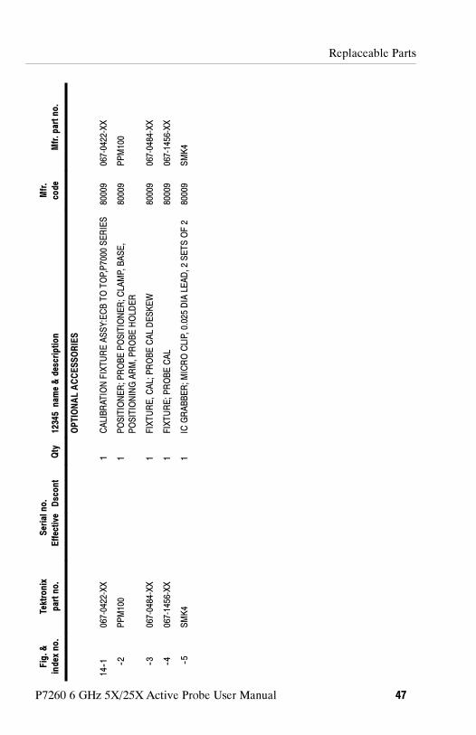
Figure14:P7260
optionalaccessories
Replaceable Parts
P7260 6 GHz 5X/25X Active Probe User Manual 47
Fig.&
index
no.
Tektronix
partno.
Serialno.
Effective
Dscont
Qty
12345nam
e&description
Mfr.
code
Mfr.partno.
OPTIONALACCESSORIES
14--1
067-0422-XX
1CALIBRATIONFIXTUREASSY:ECBTOTOP,P7000
SERIES
80009
067-0422-XX
--2PPM100
1POSITIONER;PROBEPOSITIONER;CLA
MP,BASE,
POSITIONINGARM,PROBEHOLD
ER
80009
PPM100
--3067-0484-XX
1FIXTURE,CAL;PROBECALDESKEW
80009
067-0484-XX
--4067-1456-XX
1FIXTURE;PROBECAL
80009
067-1456-XX
--5SMK4
1IC
GRABBER;MICROCLIP,0.025DIA
LEAD,2SETSOF2
80009
SMK4

Replaceable Parts
P7260 6 GHz 5X/25X Active Probe User Manual48
CROSSINDEX-MFR.CODENUMBERTOMANUFACTURER
Mfr.
Code
Manufacturer
Address
City,State,ZipCode
80009
TEKTRONIX
INC
14150SW
KARLBRAUNDR
POBOX500
BEAVERTONOR97077--0001
TK0623
GENERALTOOL&SUPPLY
CO
2705
NW
NICOLA
IST
PORTLA
ND,OR97210