pacdrive 3 error codes - home | orbit motion systems 3 error codes ... this is a class 3 error and...
TRANSCRIPT

3 Shannon Court Unit 305
Bristol RI 02809
401-213-3320
www.OrbitMotionSystems.com
PacDrive 3 Error Codes System Diagnostics………………………………………………….………1-5
Device Reactions……………………………………………………..……..6-16
Diagnostic Messages………………………………………………….….17-20
80xx Diagnostic Messages………………………………………………21-30
81xx Diagnostic Messages………………………………………………31-59
82xx Diagnostic Messages………………………………………………60-63
83xx Diagnostic Messages………………………………………………64-74
84xx Diagnostic Messages………………………………………………75-76
85xx Diagnostic Messages………………………………………………77-87
86xx Diagnostic Messages………………………………………………88-89
87xx Diagnostic Messages………………………………………….….90-110
88xx Diagnostic Messages…………………………………………...111-112
89xx Diagnostic Messages…………………………………………...113-126
Diagnostic Messages of the Runtime System……..……………...127-130

System Diagnostics 1
www.orbitmotionsystems.com Schneider Electric
Scenarios encountered at the machine
A. There may be jam due to obstacles while placing bottles, …
B. There may be friction due to fouling, worn out bearings, damaged mechanics, …
A: There may be jam due to obstacles while placing bottles, …
So, if the gripper of the robot meets an obstacle while placing the bottles into the carton, the
servo will deviate from its schedule. This deviation can be found by checking the following error.
If Following Error exceeds the given limit dramatically, there should be a reaction –say- stopping
the movement of the gripper immediately if still possible to –at least! - minimize damage of
bottles, cartons or mechanics. After a timeout, PositionControl will be switched off.
If Following Error exceeds Following Limit ‘slightly’, there should be a message but there is no
need for a reaction of the ‘reporting’ drive. The message is worth the trouble, for
programmers will use it as a criterion to launch userspecific reactions of the machine
within the userprogram,
maintenance staff can gather these messages from the message logger and use them
e.g. for ‘preventive maintenance’!
B: There may be friction due to fouling, worn out bearings, damaged mechanics, …
System Diagnostics 2
www.orbitmotionsystems.com Schneider Electric
Friction requires ‘more than the usual amount of torque’ for a given movement or for cyclic
sequences of them. Remedying this error is a bit more complex. For most of all cases, friction
within an installation is not that obvious, that it immediately disturbs the schedule like the above
obstacles did.
Friction ‘kills’ the ServoDrive in the long run. Thus the MotorController takes root mean-square
of torque – determined via root mean current- to detect this kind of ‘continuous overload’. … and
this is what we have come to know as ‘I2t’ in the previous lesson!
The above ‘warning-philosophy’ applies again:
If the drive is still functional and ‘I2t’ exceeds a certain threshold, there will be but a warning
either to be used as criterion for stopping the machine in a defined way on behalf of the
userprogram or as a message to be logged in the sense of preventive maintenance.
If ‘I2t’ reaches his utter limit, the current motion will be stopped immediately and Position Control
will be switched off after the timeout mentioned above.
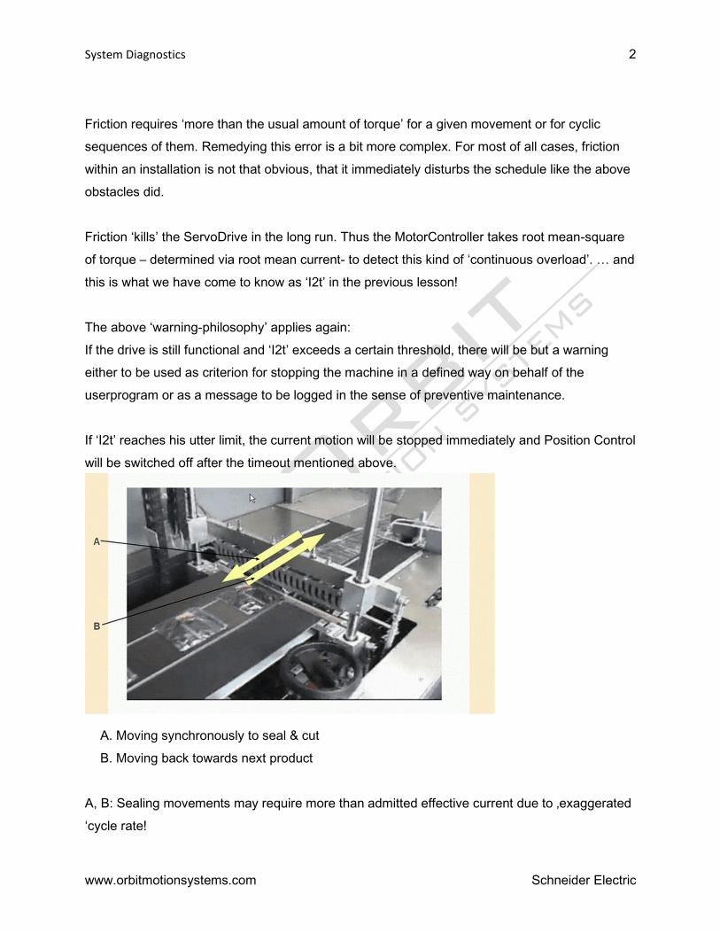
A. Moving synchronously to seal & cut
B. Moving back towards next product
A, B: Sealing movements may require more than admitted effective current due to ‚exaggerated
‘cycle rate!

System Diagnostics 3
www.orbitmotionsystems.com Schneider Electric
The motion-profiles for the up-down-movement and the back and forth movement of the sealing-
bar require acceleration- and deceleration-phases due to changing directions. Increasing cycle
rate will require more and steeper(!) accel- and decel-phases per cycle and that will result in
rising the effective values of torque and current! … and again this continuous overload will be
detected and will be reacted on to prevent heating up the Motor or the MotorController above
their admitted temperature ranges!
Diagnostic principle
‘Classification’ - in the sense of our Diagnosis Concept - is a mapping of lots of possible errors
to appropriate ‘Reactions’. Thus "Diagnosis Classes" are a set of carefully defined "Reactions"
that are provided to handle exceptional situations.
Let us consider some examples to shed more light on the above approach:
1. We have to ‘classify’ an encoder that we are not able to read as severe so that it produces a
reaction that includes switching off position control of all related drives:
If the encoder can not be read, the position of the respective drive is getting out of
control and there is danger of colliding with other drives.
To minimize damage, we have to
‘de-energize’ the drive with the severe failure
2. If reading field-bus-signals fails, that would be less grave than no communication with the
encoder mentioned above:
PositionControl does not depend on ‘field-bus’, So it remains active in this case.
Danger of injury or damage comes from the fact, that we could miss –say- a stop
signal for some of the drives under consideration due to ‘No more field bus
communication’: This is a class 3 error and does not lead to a stop of the axes. This
reaction has to be programmed by the user himself.

System Diagnostics 4
www.orbitmotionsystems.com Schneider Electric
3. If a short-circuited digital output is detected, the response will be a message and further
reaction will be left to the program, if necessary:
PacController is still working properly, MotorControllers and Motors do not report any
discrepancies and all conditions for Position Control are still given.
In this case from the point of view of Automation System there is no need to stop
some movement or to switch off drives due to something ‘getting out of control’.
… the message about what happens is desirable for operators or service-staff to
quickly find the source of the trouble!
NOTE: The above examples suggest to create “Diagnosis Classes" according to the ‘degree’ of
loosing control:
The more the components of the Automation System loose control about either themselves or
the machine the more incisive intervention is required.
Error Classes
The system assigns each diagnostic message a specific diagnostic class when enabled. The
assignment can be overwritten by the user program FC_DiagConfigSet2.
Diagnostic class Designation Priority
4 Fatal error resulting in complete stop High
3 Fatal error resulting in single stop (if error is triggered by an axis)
2 WARNING
1 Message Low
0 Deactivated None
Designation of the diagnostic classes and their priority
Certain system reactions are permanently assigned to each diagnostic class:
System reactions Diagnostic classes
4 3 2 1 0
Entry in message logger X X X X -

System Diagnostics 5
www.orbitmotionsystems.com Schneider Electric
User defined standstill of all drives (Reaction BD2) X - - - -
Configurable error reaction of the triggering drive (Reactions AD, BD1,
BD2, CD) or PowerSupply (Reactions AP, BP)
- X - - -
Inform program ( Function FC_DiagMsgRead() ) X X X X X
Activate ERROR LED X X - - -
Device state (red = X, - = green) X X - - -
Configurable X X X X X
Update diagnostic parameters of PacDrive controller X X X - -
Update diagnostic parameters of drive X X X - -
Diagnostic classes and system reactions
Also the Reactions of the drives and the Power Supply can be altered via the
functionFC_DiagConfigSet2.

Device Reactions 6
Schneider Electric
Drive Reactions
Device reactions are caused by an event taking place in a connected drive (LXM 52, LXM 62
Drive, ILM 62) or power supply unit (LXM 52, LXM 62 Power Supply). The device reaction takes
place in the device which triggered the reaction. After triggering a device reaction, a diagnostic
message which can be evaluated on the superordinated controller is transmitted.
Drive
Diagnostic messages triggered by a drive have an additional device reaction:
Device
reaction
Diagnostic
class
Subclass Meaning Priority Diagnostic
example
AD 3 6 The motor is immediately switched
to a torque-free state. By default,
the brake engages immediately.
Due to this device reaction,
the motor brake can suffer
significant wear or fail entirely.
Make absolutely sure to comply with
the safety instructions in the motor
manual regarding the security
constraints of the holding brake.
The holding brake alone does not
ensure personal safety!
The brake behavior can be changed
via the BrakeMode parameter.
High 8119
"Power
stage
short-
circuit
/ground
fault"
BD1 3 5 Best possible stop: drive is stopped
with peak current
MaxDrivePeakCurrent.
MaxDrivePeakCurrent can be
influenced via
UserDrivePeakCurrent. An
additional limit with

Device Reactions 7
www.orbitmotionsystems.com Schneider Electric
UserCurrentLimit is ineffective. The
brake engages at a speed of
rotation of less than 10 rpm. The
brake behavior can be changed via
the BrakeMode parameter. The
drive becomes torque free after
StopTimeLim + BrakeCouplingTime
at the latest. If the speed of rotation
is higher than 10 rpm after
StopTimeLim (default value: 400
ms), then the diagnostic message
8140 Motor ramp down time
exceeded is triggered.
BD2 3 4 Standstill after user default (user
defined stop): drive is brought to a
standstill with the delay
ControllerStopDec and the jerk
ControllerStopJerk. Thereby, the
current is limited with the peak
current MaxDrivePeakCurrent.
MaxDrivePeakCurrent can be
influenced via
UserDrivePeakCurrent. An
additional limit with
UserCurrentLimit is ineffective.
The actual values (standard) or
reference values are used as start
values for the stop profile
depending on the
UserDefinedStopMode parameter.
(see also UserDefinedStopMode)
The brake engages at a speed of
rotation of less than 10 rpm. The
8112
"SERCOS
telegram
invalid"
Device Reactions 8
www.orbitmotionsystems.com Schneider Electric
drive becomes torque free after
StopTimeLim + BrakeCouplingTime
at the latest. If the speed of rotation
is higher than 10 rpm after
StopTimeLim (default value: 400
ms), then the diagnostic message
8140 Motor ramp down time
exceeded is triggered.
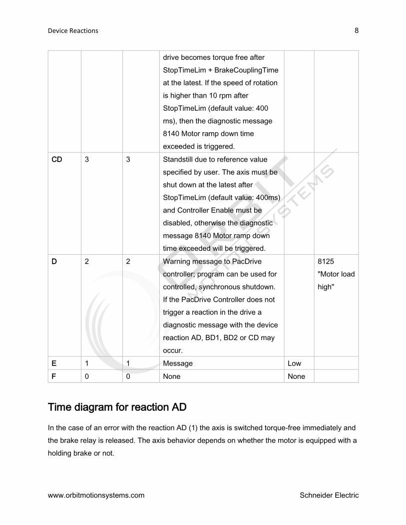
CD 3 3 Standstill due to reference value
specified by user. The axis must be
shut down at the latest after
StopTimeLim (default value: 400ms)
and Controller Enable must be
disabled, otherwise the diagnostic
message 8140 Motor ramp down
time exceeded will be triggered.
D 2 2 Warning message to PacDrive
controller; program can be used for
controlled, synchronous shutdown.
If the PacDrive Controller does not
trigger a reaction in the drive a
diagnostic message with the device
reaction AD, BD1, BD2 or CD may
occur.
8125
"Motor load
high"
E 1 1 Message Low
F 0 0 None None
Time diagram for reaction AD
In the case of an error with the reaction AD (1) the axis is switched torque-free immediately and
the brake relay is released. The axis behavior depends on whether the motor is equipped with a
holding brake or not.

Device Reactions 9
www.orbitmotionsystems.com Schneider Electric
On expiry of the BrakeCouplingTime the axis is in error state 0x10 or 0x11. From this state, the
axis can return to a controlled state following acknowledgement of the diagnosis message and
as soon as the axis has come to a standstill.
Time diagram for reactions BD1 / BD2
In case of a diagnosis message with reaction "BD1 or BD2", two sequences can occur.
Ramping down within the maximum ramp-down time
Maximum ramp-down time exceeded
Ramping down within the maximum ramp-down time
In the case of an error with reaction BD1 (1), the axis ramps down at maximum current
(MaxDrivePeakCurrent).
In the case of an error with reaction BD2 (1), the axis ramps down according to the parameters
ControllerStopDec and ControllerStopJerk.

Device Reactions 10
www.orbitmotionsystems.com Schneider Electric
As soon as the actual speed becomes lower than the speed threshold (actual speed < nmin)
(2), the brake relay is released. The axis comes to a standstill before expiry of the maximum
ramp-down time (parameter StopTimeLim) (4). After expiry of the brake coupling time
(parameter BrakeCouplingTime) (3), the motor is switched to a torque-free state.
Maximum ramp-down time exceeded
In the case of an error with reaction BD1 (1), the axis ramps down at maximum current
(MaxDrivePeakCurrent).
In the case of an error with reaction BD2 (1), the axis ramps down according to the parameters
ControllerStopDec and ControllerStopJerk.
The axis does not come to a standstill before expiry of the maximum ramp-down time
(parameter StopTimeLim) (2) (actual speed < nmin). Therefore, error message 8140 "Motor
ramp-down time exceeded" is triggered.

Device Reactions 11
www.orbitmotionsystems.com Schneider Electric
Shutting off
The system switches off the drive due to reaction AD, BD1 or BD2 (see parameter AxisState)
1. Condition ‚Enable ‘goes FALSE due to detection of an error with certain ‚severity ‘.
2. AxisState moves from ‚3’ to ‚6‘then finally to ‚0‘due to the lost condition

Device Reactions 12
www.orbitmotionsystems.com Schneider Electric
3. According to ‚severity ‘, the drive is disengaged following the above rules.
NOTE: Ready is opened in the case of an error in the PowerSupply.
4. AxisState is stuck at ‚0‘due to 'error reaction …'
… and once the system should be stuck in State “0”, inspection of the respective group of
conditions within the ‘State Folder’ of PLC-Configuration will tell us how to proceed!
Stopping
The system stops the drive due to errors with reaction C (see parameter AxisState)
1. 'Controller Stop' required due to 'Reaction' „C“.
2. Drive in 'deceleration-phase'
3. Drive stopped and still in PositionControl; System 'refuses' moving instructions.
4. Error removed and DiagMsg acknowledged: Back to accepting & processing moving
instructions.

Device Reactions 13
www.orbitmotionsystems.com Schneider Electric
De-energizing the axes
The contact rdy at the LXM 62 PS is opened, when a diagnosis message with reaction AP or BP
is triggered in the PowerSupply. The contact WD is opened, when the control fails. If one of the
contacts of the "WD & rdy" function block opens, then the power supply unit is opened too and
the devices are de-energized.
Power supply unit (PowerSupply)
Errors triggered by a "PowerSupply" have an additional device reaction:
Device
reaction
Diagnostic
class
Subclass Meaning Priority Diagnostic
example
AP 3 6 The ready contact is opened, all
allocated drives are shut down.
Braking resistor is not ready to
minimize voltage in the DC bus.
High 8144 DC bus
short-circuit
BP1 3 5 Ready contact is opened.
Braking resistor is not ready to
minimize voltage in the DC bus.
8108 DC bus
overvoltage

Device Reactions 14
www.orbitmotionsystems.com Schneider Electric
BP2 3 4 Ready contact is opened.
Braking resistor is ready to
minimize voltage in the DC bus.
8109 DC bus
undervoltage
D 2 2 Warning message to PacDrive
controller; program can be used
for controlled, synchronous
shutdown; if the PacDrive
controller does not trigger any
reaction in the drive, a
diagnostic message with the
device reaction AP, BP1 or BP2
may occur.
8961 Phase
missing
message
E 1 1 Message Low
F 0 0 None None
The device reaction can be reconfigured using the function FC_DiagConfigSet2 or
FC_DiagConfigSubClassGroupSet. The priority of the configured device reaction must always
be equal to or higher than the priority of the minimum device reaction. The minimum device
reactions are indicated in the respective diagnostic message and in the overview table.
Device display elements (LEDs)
The LEDs signify various operating states or errors.
A more detailed description of the LEDs can be found in the device-specific operating
instructions.
Acknowledging diagnosis messages
There are two ways to acknowledge diagnostic messages:
EPAS > Online > Reset Diag-Message
Function FC_DiagQuit()

Device Reactions 15
www.orbitmotionsystems.com Schneider Electric
CAUTION
POSITION LOSS DUE TO SERIOUS SERCOS BUS ERROR!
Loss of position of the axes and physical encoders (SinCos, incremental encoder) is
possible as a consequence of error acknowledgement of diagnostic message 8506
"SERCOS Master communication not possible" without restarting the controller.
Acknowledge the diagnosis message only after re-initialization or homing of the
system has been ensured by the program.
The capability to acknowledge the diagnostic message can be switched off with the
function FC_DiagNoQuitSet().
If necessary, use the functions FC_SysReset() or FC_PrgResetAndStart().
Failure to follow these instructions can result in injury or equipment damage.
Note that acknowledging a diagnostic message does not eliminate the cause of the error.
Acknowledgement serves to confirm that I have "seen" the message. By acknowledging, the
diagnostic message in the PacDrive system will be deleted. If the cause of the diagnostic
message remains, then that diagnostic message will be redetected in the PacDrive system.
With the following errors, it is also necessary to reset the triggering device for reasons of safety
and due to the far reaching consequences of the error. This occurs with the reset button on the
device or by switching the device's control voltage off and on again.
8105 "Feedback error (track monitoring)"
8107 "Over-current"
8113 "Braking resistor error detected"
8114 "Device type plate not readable"
8115 "Gate-power failure"
8117 "Motor type plate not readable"
8118 "Error on ser. interface to encoder"
8119 "Power stage short-circuit /ground fault"
8138 "Motor/Drive combination not supported"
8144 "DC bus short-circuit"
8145 "DC bus ground fault"

Device Reactions 16
www.orbitmotionsystems.com Schneider Electric
8153 "DC bus discharge not possible"
8209 "Last boot failed"
8826 "PIC update not possible"
8904 "Software error detected (class 4)"

Diagnostic Messages 17
Schneider Electric
Diagnostic messages
Diagnosis
Code
Diagnostic
code message
Diagnostic
class
(standard)
Default
reaction
drive
Minimum
reaction
drive
Default
reaction
power
supply
Minimum
reaction
power
supply
8100 Motor overload 3 BD2 BD2 - - -
8101 Power stage
overtemperature
3 BD2 CD - - -
8104 Control voltage
out of range
3 BD2 CD BP1 BP1 LXM52
8105 Encoder signal
out of range
3 AD AD - -
8106 DC bus contr.
communication
not possible
3 AD AD AP AP
8107 Excess current 3 AD AD AP AP
8108 DC bus
overvoltage
3 AD AD BP1 BP1
8109 DC bus
undervoltage
3 BD2 BD2 CD BD2
8110 Phase missing 3 BD2 BD2 CD BD2 LXM52
8111 Shutdown due
to tracking
deviation
3 BD2
(BD1 in
V3.1)
- -
8112 SERCOS
telegram invalid
3 BD2 BD2 BD2 BD2
8114 Device type
plate not
readable
3 AD AD AP AP
8116 Commutation
error detected
3 AD AD - -
8117 Motor type
plate not
readable
3 AD AD - -
8119 Power stage
short-circuit
/ground fault
3 AD AD - -
8120 Power stage
overload
3 BD2 CD - -
8122 Shutdown due
to velocity limit
3 BD2 CD - -
8123 Safe Torque Off
incorrect
3 AD E - -
8125 Motor load high 2 D E - -

Diagnostic Messages 18
www.orbitmotionsystems.com Schneider Electric
8126 Power stage
temperature
high
2 D E - -
8127 Motor
temperature
high
2 D E - -
8129 Power stage
load high
2 D E - -
8132 Tracking
deviation limit
exceeded
2 D E - -
8133 Speed-
dependent
current
reduction
2 D E - -
8134 External 24
VDC too low
2 D E D E
8135 DC bus voltage
low
2 D E D E
8136 Safe Torque Off
active
2 D E - -
8137 Motorless 3 AD AD - -
8138 Motor/Drive
combination not
supported
3 BD2 - -
8139 DC bus
precharge not
possible
3 - - BP1 BP1
8140 Motor
StopTimeLim
exceeded
3 BD1 BD1 - -
8142 Control board
overtemperature
3 BD2 CD BP1 BP1
8143 Encoder
temperature
high
2 D E - -
8144 DC bus short-
circuit or
ground fault
3 - - AP AP
8146 DC bus
overload
3 - - BP1 BP1
8153 DC bus
discharge not
possible
3 - - BP1 BP1
8157 DC bus load
high
2 - - D E

Diagnostic Messages 19
www.orbitmotionsystems.com Schneider Electric
8161 Control board
temperature
high
2 D E D E
8169 SERCOS Slave
comm.
disturbance
detected
2 D E D E
8170 Encoder
position not
accessible
3 BD2 D - -
8171 Encoder comm.
disturbance
detected
2 D D - -
8177 Power board
overtemperature
2 - - BP1 BP1
8179 Braking resistor
load high
2 - - D E
8180 Power board
temperature
high
2 - - D E
8182 External 24
VDC power
supply high
1 D E D E
8183 Device fallback
firmware active
3 AD AD AP AP
8184 HW/SW
combination not
supported
3 AD AD AP AP
8185 Device error
detected
3 AD AD AP AP
8186 DC bus voltage
high
2 D E D E
8788 Wiring error
detected
2 D E - -
8790 Module error
detected
3 D E - -
8906 ControlMode
invalid
3 AD AD - -
8907 Encoder
interface invalid
3 AD AD - -
8908 Unintended
motor reaction
detected
3 AD E - -
8909 Motor
nameplate
3 AD AD - -

Diagnostic Messages 20
www.orbitmotionsystems.com Schneider Electric
parameter
invalid
8910 Reference value
invalid
3 BD1 E - -
8958 Encoder
communication
not possible
3 BD2 CD - -
8959 Mains contactor
error detected
3 - - BP1 BP1
8960 Invalid setting
of the mains
voltage
2 - - D E
8961 Phase failure
message
2 - - D E
8969 Motor supply
cable not
connected
3 AD AD - -
8975 Motor
commutation
invalid
2 D E - -
8976 Mains phases
wiring not
correct
3 - - BP1 BP1
8977 Motor temp.
monitoring
disabled
2 D E - -

80xx Diagnostics Messages 21
Schneider Electric
8001 Diagnosis acknowledgement
Diagnostic class (standard): 1
A diagnosis message was acknowledged.
This message is always entered in the message logger even if the diagnostic class of the
message was set to 0 using the FC_DiagConfigSet() function.
8002 Controller boot started
Diagnostic class (standard): 1
The PacDrive controller was restarted.
In the ext. diagnosis in the message logger, the firmware version is displayed.
8003 Controller boot finished
Diagnostic class (standard): 1
The startup procedure for the PacDrive controller is complete.
In the ext. diagnosis in the message logger the Kernel-Version is displayed.
8004 Program started
Diagnostic class (standard): 1
The program was started in the PacDrive controller.
8005 Program automatic start active
Diagnostic class (standard): 1
The autom. program start of the program is active in the PacDrive controller.
8006 Program stopped
Diagnostic class (standard): 1
The program in the PacDrive controller has been stopped.
8007 Controller login
Diagnostic class (standard): 1
A login to the PacDrive controller was performed. In the ext. diagnosis the application that
performed the login (for example, Logic Builder) is displayed.
8008 Controller logout
Diagnostic class (standard): 1
A logout from the PacDrive controller was performed. In the ext. diagnosis the application that
performed the logout (for example, Logic Builder) is displayed.
8009 Program reset
Diagnostic class (standard): 1
A program reset was triggered via Logic Builder.
8010 write file
Diagnostic class (standard): 1

80xx Diagnostics Messages 22
www.orbitmotionsystems.com Schneider Electric
File transfer via communication server. The file name is displayed in DiagExtMsg.
8013 Controller connect to TCP/IP server
Diagnostic class (standard): 1
Connecting to communication server of PacDrive controller.
8014 Controller disconnect from TCP/IP server
Diagnostic class (standard): 1
Disconnecting from communication server of PacDrive controller.
8015 filesystem <ide0:> repaired
Diagnostic class (standard): 1
Error detected in the file system and corrected.
NOTE: The file system is consistent again. This may also mean that files have been deleted.
8016 Controller reset
Diagnostic class (standard): 1
warm start
8017 CanOpen emergency message reset
Diagnostic class (standard): 1
A CANopen node has sent a CANopen emergency message reset to the bus.
Meaning of ext. diagnosis:
The system displays the node address, the error code and the error register.
Structure: Nxxx Cxxxx Rxx
N node address decimal CANopen node address
C error code hexadecimal CANopen error code
R error register hexadecimal CANopen error register.
8018 CanOpen node guarding error resolved
Diagnostic class (standard): 1
A CANopen node has sent a CANopen emergency message reset to the bus.
A CANopen node has reported the disappearance of a monitoring error
Meaning of ext. diagnosis:
The system displays the node address, the error code and the error register.
Structure: Nxxx Cxxxx Rxx
N node address decimal CANopen node address
C error code hexadecimal CANopen error code

80xx Diagnostics Messages 23
www.orbitmotionsystems.com Schneider Electric
R error register hexadecimal CANopen error register.
8019 CanOpen node error info
Diagnostic class (standard): 1
A CANopen node has sent an emergency message to the bus. This diagnosis message is
always sent with the 8754 "CanOpen emergency message" diagnosis message. It contains
manufacturer-specific error data. This data consists of 5 byte values.
Meaning of ext. diagnosis:
Structure: b1 b2 b3 b4 b5
b1-b5 hexadecimal date
8020 Program cycle check has changed
Diagnostic class (standard): 1
With the function FC_CycleCheckSet(), the cycle check was switched on or off. In DiagExtMsg,
TRUE or FALSE is displayed
8021 Program cycle check values are changed
Diagnostic class (standard): 1
By means of the function FC_CycleCheckSet(), the times for the simple and serious cycle check
have been changed. The times are shown in DiagExtMsg.
8022 FC_SetTaskPriority() called
Diagnostic class (standard): 1
The function FC_SetTaskPriority() has been called up.
8023 Controller shutdown
Diagnostic class (standard): 1
FC_SysShutdown is used via:
Function: FC_SysShutdown()
UPS shutdown
8027 File write open
Diagnostic class (standard): 1
8028 File write close
Diagnostic class (standard): 1
8029 UPS OK
Diagnostic class (standard): 1
UPS monitoring reports "UPS ok" (State = 1).
8030 UPS active - no power
Diagnostic class (standard): 1

80xx Diagnostics Messages 24
www.orbitmotionsystems.com Schneider Electric
The UPS monitoring reports that no power is available (State = 3).
8031 UPS power supply OK
Diagnostic class (standard): 1
UPS monitoring reports that the power supply is OK.
8032 UPS begin saving retain area
Diagnostic class (standard): 1
At shutdown, via UPS monitoring, saving retain area has been started.
8033 UPS retain area saved
Diagnostic class (standard): 1
At shutdown, via UPS monitoring, saving retain area has been terminated.
8034 UPS program tasks terminated
Diagnostic class (standard): 1
At shutdown, via UPS monitoring, the tasks have been terminated.
8035 UPS active - system shutdown started
Diagnostic class (standard): 1
During shutdown, the output O_OffValue to switch off the UPS was set via the UPS monitoring.
8036 UPS controller rebooting started
Diagnostic class (standard): 1
At shutdown, via UPS monitoring, the power supply of the PacDrive controller was found to be
OK. A reboot of the PacDrive controller was initiated.
8037 Battery low
Diagnostic class (standard): 2
The battery voltage has dropped below the permissible minimum value.
The battery voltage is too low.
Change the battery for the PacNet optional module PN-4.
8038 NvRam/RTC power fail detected
Diagnostic class (standard): 2
A power failure has occurred at the NvRam and the real-time clock (RTC). The NvRam
has been deleted and the system time is incorrect.
The system was shut off for too long and the battery power is too low.
Retain range and reinitialize clock.
Change the battery for the PacNet optional module PN-4.
8042 SERCOS phase switched
Diagnostic class (standard): 1

80xx Diagnostics Messages 25
www.orbitmotionsystems.com Schneider Electric
A SERCOS phase change has occurred. In the message logger in „Ext. diagnosis" the new
phase is displayed.
DiagExtMsg Meaning
CP0 Phase change after Phase 0
CP1 Phase change after Phase 1
CP1/scan=(x) The SERCOS phase has been changed to CP1. Here, (x) real SERCOS 3
subscribers have been found.
CP=1/xxx Internal error xxx during phase change after phase 1.
CP=2 Phase change after Phase 2
CP2/use=(x) The SERCOS phase has been changed to CP2. Here, (x) real SERCOS 3
subscribers have been assigned logical objects from the PLC configuration.
The remaining real SERCOS 3 devices are taken to phase 4 without any
connection to logical objects in order to ensure ring healing and redundancy.
CP=2/xxx Internal error xxx during phase change after phase 2.
CP=3 Phase change after Phase 3
CP=3/xxx Internal error xxx during phase change after phase 3.
CP=4 Phase change after Phase 4
CP=4/xxx Internal error xxx during phase change after phase 4.
Possible values for DiagExtMsg for diagnosis message 8042 "SERCOS phase change"
"CP=<Phase number>/<internal error number>":
An error occurred when the phase changed.
Check the message logger for other SERCOS diagnosis messages.
Note the description of these diagnosis messages.
8043 SERCOS detect configuration
Diagnostic class (standard): 1
The SERCOS configuration is being detected. During the detection a scan is processed.

80xx Diagnostics Messages 26
www.orbitmotionsystems.com Schneider Electric
Ext.
diagnosis
Meaning
Start Configuration scanning started.
Position The physical address of the instance in the SERCOS loop and the device type
is shown (e.g. instance "SLAVE1" Pos=03). If the device type cannot be
determined, then "Type=yyy" is eliminated.
In controller version 00.23.00 or lower, the device type is not displayed.
End Configuration scanning was stopped.
No slaves No SERCOS slaves found.
Duplicate There are several devices with the same address in the SERCOS loop. The
additional "xxx" indicates the loop position in which the last device with a
duplicate address was found.
Meaning of ext. diagnosis:
8044 SERCOS firmware download
Diagnostic class (standard): 1
A firmware download is being executed from the PacDrive controller to a SERCOS bus slave.
The “ext. diagnose” in the message logger shows the following values:
DL start -> Firmware download started
Dl x OK -> Successful firmware download to slave x (x is the RealTimeBusAdr)
8045 File write error detected
Diagnostic class (standard): 1
Error occurred when writing in a file.
Insufficient memory space.
Check to see that memory capacity is sufficient (parameter RamDiskFree, Diskfree).
Increase the RamDiskSize. (The default size is 1MByte.)
An attempt was made to write a trace file to the RAM disk (“ram0”).
Increase the RamDiskSize. (The default size is 1MByte.)
8046 FPGA firmware download
Diagnostic class (standard): 1
After programming of the FPGA or in the case of errors, this diagnostic message is triggered.

80xx Diagnostics Messages 27
www.orbitmotionsystems.com Schneider Electric
The various causes for this message are displayed through different external diagnosis codes.
Below is a summary of all external diagnosis codes along with their causes and means of
correction:
DiagExtMsg: Cx3_xpxx.BIN (e.g. Cx3_0604.BIN)
The FPGA firmware was programmed successfully. The DiagExtMsg now indicates the
name of the programmed FPGA file.
DiagExtMsg: Update: x (e.g. Update: -1181)
An error has occurred during the FPGA firmware download. By means of the error
number the contact partner can determine the cause of the error.
Consult the contact partner to obtain a correct FPGA firmware file.
8047 PIC firmware download
Diagnostic class (standard): 1
The firmware of the PIC controller is replaced. In DiagExtMsg, the file name of the firmware file
can be read.
If an error occurs during the firmware exchange, the 8826 "PCI update error" diagnosis
message will be triggered.
8048 BT-4 firmware download
Diagnostic class (standard): 1
The firmware of the bus terminal BT-4/DIO1 or BT-4/ENC1 is replaced.
Other requirements:
Firmware file for BT-4/DIO1: "BD1_xxxx.ESV"
Firmware file for BT-4/ENC1 : "BE1_xxxx.ESV"
To execute the update, the firmware file for the BT-4/DIO1 or BT-4/ENC1 bus terminal must be
copied to the root directory of the controller. The update will be automatically executed at the
next startup.
NOTE: After the update, all BT-4/DIO1 or BT-4/ENC1 bus terminals must be switched off and
on. A standard reset on the controller is sufficient.
The update will only be executed if a bus terminal has a differing firmware version.
8051 Controller type
Diagnostic class (standard): 1
The PacDrive controller was restarted (rebooted). Shortly before the start procedure ends, the
controller type will be saved as a diagnosis message in the message logger.
NOTE: The controller type may not be displayed in full, as the message text does not have
enough characters.
8053 UPS active overtemperature
Diagnostic class (standard): 1

80xx Diagnostics Messages 28
www.orbitmotionsystems.com Schneider Electric
The system has detected a temperature that is too high and will change the state to “System
Shutdown/4” after 70 seconds.
8054 Controller temperature out of range
Diagnostic class (standard): 2
The temperature in the device is outside the specified range. This can cause the controller to
shut itself off.
DiagExtMsg: Temp<5°C
The temperature in the device is lower than approx. 5 °C.
The following message text appears on the display:
1st line: Temperature warning
3.Zeile: Temp. < 5 °C
This message can be acknowledged.
The temperature of the surroundings decreases significantly. The switch cabinet door
may be open.
Check ambient temperature.
The device will be switched on and the ambient temperature is too low.
Check ambient temperature.
DiagExtMsg (Controller LMC x01C): tl:xx<t:yy
The temperature in the device exceeds the maximum temperature limit of 80 °C that is set in
the hardware.
Character Meaning
xx Temperature limit in °C (the current setting of the hardware is 80 °C).
yy Measured temperature in °C.
The ambient temperature is increasing markedly. Maybe the cooling unit has failed.
Check ambient temperature.
The device is switched on and the ambient temperature is too high.
Check ambient temperature.
8055 Controller message HW monitor
Diagnostic class (standard): 1
MsgFilter: Bit 14 "Filter Type 15"
See also:
Diagnosis message 8056 "Supply voltage low"
Diagnosis message 8827 "Controller power-off/hardware monitor"
DiagMsg:
-specific diagnosis message for debugging purposes

80xx Diagnostics Messages 29
Schneider Electric
Structure: <last error entry> : <error group>
: <cause of error>
Error groups:
- VoltageError
- TempError
- EnvError
Cause of error (VoltageError):
- V3.3 < Vmin
- V5 < Vmin
- V+12 < Vmin
- V-12 < Vmin
- Vin < Vshutd
- VAccu < Vshutd
- Vin_jit < Vshutd
- capacitance
- LTC error
- Vin > Vmax
- VAccu > Vmax
- V3.3 > Vmax
- V5 > Vmax
- V+12 > Vmax
- V-12 > Vmax
- VcpuCore<Vmin
- VcpuIO < Vmin
- VM2.5 < Vmin
- VM3.3 < Vmin
- VM5 < Vmin
- VM+12 < Vmin
- VM-12 < Vmin
- VcpuCore>Vmax
- VcpuIO > Vmax
- VM2.5 > Vmax
- VM3.3 > Vmax
- VM5 > Vmax
- VM+12 > Vmax
- VM-12 > Vmax
Cause of error (TempError):
- Vin < Vmin
- VAccu < Vmin
- TAccu < Tmin
- TLM75 < Tmin
- TCPU < Tmin
- TM1 < Tmin
- TM2 < Tmin
- TAccu > Tshutd
- TLM75 > Tshutd
- TCPU > Tshutd
- TM1 > Tshutd
- TM2 > Tshutd
- TAccu > Tmax
- TLM75 > Tmax
- TCPU > Tmax
- TM1 > Tmax
- TM2 > Tmax
- I2C bus failed
- LM75 failed
Cause of error (EnvError):
- fan1stop-shutd
- fan1stop-off
- fan2stop-shutd
- fan2stop-off
- fan3stop-shutd
- fan3stop-off
Example of message text:
-1 : TempError : TLM75 > Tshutd
-The error was in the last created error entry. It is a temperature error in which the LM75 sensor
detected a temperature that is too high. The shutdown limit was exceeded, and so the system
shut down after the timer ran out.
8056 Controller power supply low
Diagnostic class (standard): 1
MsgFilter: Bit 1 "Diagnosis Messages"

80xx Diagnostics Messages 30
www.orbitmotionsystems.com Schneider Electric
The hardware provides an internal error logger that logs all the causes for error-dependent
controller deactivations. The next time the controller is started up the error logger is analyzed
and the cause of the error can be output in the message logger. If the reason for the shutdown
was a supply voltage outage, message 8056 “Controller power supply low” is output.
In addition, a more specific message is output (8055 “Controller message HW monitor”) that can
be enabled by the MsgFilter parameter and activated via the Logic Builder message logger. This
message is intended to be a debug message and outputs the exact cause of the deactivation.
8057 Program online change
Diagnostic class (standard): 1
Filter type 13 "extended system messages"
An online change was performed.
8059 UPS active - IEC-control task running
Diagnostic class (standard): 1
8060 UPS changing state
Diagnostic class (standard): 1
Filter type 13 "extended system messages"
With the assistance of the monitoring task, it is possible to respond to specific events in a fast
task. The UPS uses this tool to delay the shutdown of the PacDrive Controllers, so that certain
actions defined in an application can be executed before the system is switched off.
For this purpose, an event starting the configured monitoring task is triggered for the following
changes in the UPS state machine:
UPS.State = 3 – UPS active – no power
UPS.State = 4 – UPS active – system shutdown started
UPS.State = 6 – UPS active – system temperature too high
The diagnostic message 8060 "UPS changing state" is output if a monitoring task already
started by the UPS is still active at the following UPS state changes:
UPS.State=3 -> UPS.State=4
UPS.State=3 -> UPS.State=6
UPS.State=6 -> UPS.State=4

81xx Diagnostics Messages 31
Schneider Electric
8100 Motor overload
Diagnostic class (standard): 3
Default reaction Minimum reaction
Drive BD2 CD
Power Supply - -
The motor is overloaded or the power supplied to the motor is too high. The integrator has
increased to 100 %. The motor monitoring is performed with the help of an integrator that is
derived from the following equations. The current overload of the drive will be shown in the
parameter DriveOverload.
The holding brake is not released (cable break, power outside the 24 V +/- 10% range).
Check the brake and the wiring.
The lubrication system is not functioning correctly.
Check lubrication.
Blunt tool.
Check/replace the tool.
The motor is vibrating.
Check the controller parameters.
The suspended axis is too heavy / the weight compensation is incorrect.
Check drive sizing and weight distribution.
Drive/accelerate the system at a slower speed.
The motor is de-magnetized.
Replace the motor.
8101 Power stage overtemperature
Diagnostic class (standard): 3
Default reaction Minimum reaction
Drive BD2 CD
Power Supply - -
The cooling element of the PacDrive servo amplifier is too hot.
Insufficient ventilation or ambient temperature too high.
Check device fans and ventilation slots (if available).
Check ventilation in switching cabinet.
If installed, make sure the air conditioning unit is functioning properly.
The power stage or the power rectifier is overloaded.
Check combination motor / drive.
Check calculation of motor and drive.
Hardware error: The temperature sensor is defective.
Replace the device.

81xx Diagnostics Messages 32
www.orbitmotionsystems.com Schneider Electric
8102 Motor overtemperature
Diagnostic class (standard): 3
Default reaction Minimum reaction
Drive BD2 CD
Power Supply - -
The internal motor temperature (temperature switch in the motor) is too high (approx. 130°C).
In versions ≤ V01.31.13.00 this error is triggered additionally, if no Hiperface communication
with the encoder is possible for more than 1 minute and therefore the current encoder
temperature cannot be detected anymore. This error must be triggered as the encoder
temperature is used for the thermal monitoring of the motor.
Wiring error: The temperature switch in the motor winding is not connected properly.
Check the wiring.
Wiring error: The shielding of the motor cable is not attached properly.
Check the shielded terminal on the bottom of the servo amplifier and the terminal boxes
of the motor.
Holding brake not vented.
Release the brake.
The motor is overloaded.
Drive the system at a slower speed.
Check drive sizing.
Use a larger motor for this application.
Commutation error, i.e. the encoder is not aligned / leveled.
Align / level the encoder.
Hardware error: The temperature switch in the motor winding is defective.
Replace the motor.
8104 Control voltage out of range
Diagnostic class (Default): 3
Default reaction Minimum reaction
Drive BD2 CD
Power Supply BP1 BP1
This diagnostic message is triggered if the control voltage (24 V DC) is not within the permitted
range anymore.
The drive was stopped because an error-free function of the device could no longer be ensured.

81xx Diagnostics Messages 33
www.orbitmotionsystems.com Schneider Electric
The control voltage is too high or too low.
Check the control voltage (see technical data of the device).
8105 Encoder signal out of range
Diagnostic class (standard): 3
Default reaction Minimum reaction
Drive AD AD
Power Supply - -
A hardware encoder error has occurred. The device that triggered this error must be reset.
Wiring error: Encoder cable at the encoder or the servo amplifier / PacDrive controller
has been removed or is defective.
Check the encoder cable and replace if necessary.
Check the ground connection (shield).
The encoder voltage is unavailable or incorrect.
Check the encoder voltage.
The control voltage of the device (24V DC) is too low.
Check control voltage.
Hardware error: Encoder is defective.
Replace the encoder.
8106 DC bus contr.communication not possible
Diagnostic class (standard): 3
Default reaction Minimum reaction
Drive AD AD
PowerSupply AP AP
An internal system error has occurred.
EMC faults.
Reset the PacDrive system (PacDrive controller and servo amplifier).
Hardware error: Servo amplifier defective.
Replace the servo amplifier.
8107 Overcurrent
Diagnostic class (standard): 3

81xx Diagnostics Messages 34
www.orbitmotionsystems.com Schneider Electric
Default reaction Minimum reaction
Drive AD AD
Power Supply AP AP
The current through the power stage of the servo amplifier or in the DC bus of the power supply
is too high. In contrast to the diagnosis messages 8120 "Power stage overload" and 8146 "DC
bus overload", the device is switched off immediately if the maximum current is exceeded.
Wiring error: The shielding of the motor cable is not attached properly.
Check the wiring.
Servo amplifier: The current controller parameters are incorrect.
Check the power control parameters Curr_P_Gain, Curr_I_Gain and CurrFilter and set
them to default, if necessary.
Hardware error servo amplifier: The motor has a short circuit.
Replace the motor.
8108 DC bus overvoltage
Diagnostic class (standard): 3
Default reaction Minimum reaction
Drive AD AD
Power Supply BP BP
The DC bus voltage is too high.
In the LXM62 PS this detected error message is triggered if the DC bus voltage exceeds the
maximum voltage of the device.
In the LXM52, LXM62 D and ILM62 drive module the maximum voltage of the device and the
maximum voltage of the motor are considered. As soon as the DC bus voltage exceeds one of
both values, this diagnostic message will be triggered.

81xx Diagnostics Messages 35
www.orbitmotionsystems.com Schneider Electric
Device Threshold DC bus voltage
Maximum voltage of the device Maximum voltage of
the motor*)
LXM52 820 V DC Yes
LXM62 D 900 V DC Yes
LXM62 PS 410 V DC, if BrakingResistorMode is set to
"230V mode / 0".
850 V DC, if BrakingResistorMode is set to
"400V mode / 1" (default value).
no
ILM62 Drive
Module
930 V DC Yes
*) Yes = The maximum voltage of the motor is being considered as threshold
The voltage threshold for this diagnostic message is only dependent on the parameter
BrakingResistorMode. The parameter MainsVoltageMode has no influence on this threshold.
Beforehand the diagnostic message 8109 DC bus undervoltage was triggered. After this
diagnostic message has been triggered the braking resistor (Bleeder) is switched to the
precharge function. This is why it is not possible to extract feed in energy from the drive
via the braking resistor. The braking resistor can only be used to decrease feed back
energy after a successful precharge.
Stop the drives in the application before the diagnostic message 8109 DC bus
undervoltage is triggered.
- Stopping the drives with the diagnostic message 8135 DC bus voltage low or
- Stopping the drives with the parameter DC_BusVoltage.
Wiring error: Braking resistor is not connected.
Connect braking resistor.
The braking energy of the motor that is fed back into the DC bus is too high. This leads
to an increase in voltage.
Brake at a slower rate.
Check the dimensioning of the braking resistor.
Use additional braking resistor for 400 V AC devices.
The mains voltage is too high.
Check the mains supply.
Hardware error: Servo amplifier defective.
Replace the servo amplifier.

81xx Diagnostics Messages 36
www.orbitmotionsystems.com Schneider Electric
8109 DC bus undervoltage
Diagnostic class (standard): 3
Default reaction Minimum reaction
Drive BD2 E, (CD for LXM52)
Power Supply BP2 BP2
The DC bus voltage is too low.
Device Thresholds
LXM52 380 V DC in 400 V AC operation
LXM62 D 380 V DC in 400 V AC operation
180 V DC in 230 V AC operation
LXM62 PS 400 V DC in 400 V AC operation
200 V DC in 230 V AC operation
ILM62 Drive Module 380 V DC in 400 V AC operation
180 V DC in 230 V AC operation
The mains voltage is too low.
Check the mains voltage (see technical data).
The power supply has detected an error and the "Ready" signal is switched off. The
motor has run on until the DC bus voltage has decreased too far.
Remove error in the power supply.
The DC bus was overloaded.
Run motors with reduced acceleration, adapt motion profiles.
NOTE: Valid as of version V01.36.16.00: the braking resistor is controlled also after an
undervoltage error in the power supply unit. This might be necessary if too much energy is
supplied in the DC bus because all motors slow down on a mains power failure.
NOTE: Valid as of version V01.36.12.00: after this diagnostic message has been triggered, the
braking resistor (Bleeder) is switched to the precharge function. This is why it is not possible to
extract feed in energy from the drive via the braking resistor. The braking resistor can only be
used to decrease feed back energy after a successful precharge.

81xx Diagnostics Messages 37
www.orbitmotionsystems.com Schneider Electric
8110 Phase missing
Diagnostic class (Default): 3
Default reaction Minimum reaction
Drive BD2 CD
Power Supply BP2 BP2
This diagnostic message is triggered if a phase of the mains connection is interrupted for more
than 1 second.
The drive is stopped to protect the device from overload.
A phase of the mains connection is not connected to the device.
Check the wiring of the mains connection.
8111 Shutdown due to tracking deviation
Diagnostic class (standard): 3
Version Default reaction Minimum reaction
Drive PacDrive 3 V 3.1 BD1 BD2
PacDrive 3 V 3.1 SP1 and higher BD2 BD2
Power Supply - -
A major tracking deviation has occurred which is higher than 8 times the value of the
TrackingDeviationLimit.
This error normally occurs in connection with the CAM movement functions (for
example, MultiCam() ).
Check curve data.
The axis should be operated at regulated speeds.
Set parameter Pos_P_Gain to "0".
8112 Sercos telegram invalid
Diagnostic class (Default): 3

81xx Diagnostics Messages 38
www.orbitmotionsystems.com Schneider Electric
Default reaction Minimum reaction
Drive BD2 BD2
Power Supply BP2 BP2
The device (sercos Slave) did not receive a valid telegram or valid data over the real-time bus
(sercos) during the sercos phases 3 or 4. The diagnostic message is triggered after two
consecutive data breakdowns or 10 consecutive telegram breakdowns.
NOTICE
EVALUATION OF DIAGNOSTIC MESSAGE NOT POSSIBLE DUE TO INTERRUPTED CONNECTION
The diagnostic message 8112 "sercos telegram invalid" is not triggered for telegram breakdowns
within the system since the sercos slave can no longer report the diagnostic code to the
controller via the sercos bus. In this case, diagnostic code 8506 "sercos Master communication
not possible" is reported.
While evaluating diagnostic message 8112 "sercos telegram invalid", diagnostic message 8506 "sercos
Master communication not possible" must be evaluated additionally in order to ensure specific reaction
also during telegram breakdowns.
Failure to follow these instructions can result in equipment damage.
Hardware error: cable disconnected / defective.
Check cable.
Replace cable.
Hardware error: Device is defective
Replace the device.
8114 Device type plate not readable
Diagnostic class (standard): 3
Default reaction Minimum reaction
Drive AD AD
Power Supply AP AP
The electronic device type plate cannot be read or contains invalid data.

81xx Diagnostics Messages 39
www.orbitmotionsystems.com Schneider Electric
The nameplate contains e.g. the device type, serial number, alignment values, etc.
Hardware error: Device is defective.
Contact customer service.
Replace the servo amplifier.
8116 Commutation error detected
Diagnostic class (standard): 3
Default reaction Minimum reaction
Drive AD AD
Power Supply - -
Unable to determine the commutation.
Motor turns when starting (boot procedure) the servo amplifier.
Make sure that the motor is still when starting (boot procedure) the servo amplifier.
Wiring error: encoder cable is not plugged in or defective.
Check the wiring.
Error when determining the motor commutation (MotorCommutationControl).
The cause is displayed via the parameter MotorCommutationState.
8117 Motor type plate not readable
Diagnostic class (standard): 3
Default reaction Minimum reaction
Drive AD AD
Power Supply - -
The electronic motor type plate cannot be read from the EEPROM encoder or contains invalid
data.
Wiring error detected: The encoder cable is not correct.
Check the wiring.
The control voltage of the device (24V DC) is too low.
Check control voltage.
Hardware error detected: The encoder is defect.
Exchange the motor or the encoder.
The setting of the parameter MotorIdentification is wrong. (in the logger of the drive the
"Parameter 1" has the value "407").
Set "MotorIdentification" to the correct value.

81xx Diagnostics Messages 40
www.orbitmotionsystems.com Schneider Electric
8119 Power stage short-circuit /ground fault
Diagnostic class (standard): 3
Default reaction Minimum reaction
Drive AD AD
Power Supply - -
The motor and motor lines are checked for short circuits (phase short circuit).
Wiring error: Short circuit in motor cable.
Replace the motor cable.
Hardware error: Short circuit in the motor (phase to phase or phase to housing).
Replace the motor.
Hardware error: power stage in servo amplifier defective.
Replace the servo amplifier.
8120 Power stage overload
Diagnostic class (standard): 3
Default reaction Minimum reaction
Drive BD2 CD
Power Supply - -
The power stage is overloaded. In this case, unlike diagnostic message 8107 "over-current",
switch off does not occur as soon as the current threshold has been exceeded. The thermal
overload of the device is observed for a specific period of time. The current overload of the drive
will be shown in the parameter DriveOverload.
The power stage is overloaded.
Check combination motor / drive.
Check calculation of motor and drive.
Drive the system at a slower speed.
The motor brake is not open.
Check the wiring of the motor brake (voltage reversal, cable break …).
Hardware error: Servo amplifier defective.
Replace the servo amplifier.
Valid only for Lexium LXM52: The device is operated without a power choke.
Connect power choke and set the parameter MainsChokeConnected to "on / 1".

81xx Diagnostics Messages 41
www.orbitmotionsystems.com Schneider Electric
8121 Braking resistor – overtemperature
Diagnostic class (standard): 3
Reaction: B
The bleeder is overloaded.
The drive sizing is incorrect.
Check drive sizing.
Hardware error detected: The braking resistor or triggering is defective.
Contact customer service.
8122 Shutdown due to velocity limit
Diagnostic class (standard): 3
Default reaction Minimum reaction
Drive BD2 CD
Power Supply - -
The active speed of rotation is higher than the maximum speed of rotation of the motor, that
means 111.1% of MaxVel is exceeded.
Error occurs on a CAM movement function (e.g. MultiCam() ) due to incorrect curve or
profile data.
Check curve data and program.
Jumps occurred in the master encoder.
Check the master encoder.
The error occurs on a CAM movement function due to an incorrect position manipulation
(e.g. FC_SetposSingle() function).
Check the program.
Hardware error: Commutation error, i.e. the motor encoder (SinCos) is not calibrated or
leveled.
Contact customer service.
8123 Safe Torque Off incorrect
Diagnostic class (standard): 3
Default reaction Minimum reaction
Drive AD E
Power Supply AP E
The "Inverter Enable" input changed to LOW while the drive was "under control" (AxisState >1).

81xx Diagnostics Messages 42
www.orbitmotionsystems.com Schneider Electric
This is not permitted if the safety function "Safe Stop 1" is used.
NOTE: If the drive is shut down with ControllerEnable, then the controller is active until the drive
stops and the brake is engaged (BrakeCouplingTime).
Wiring error.
Check wiring of "Inverter Enable" input.
Circuit error: The "Inverter Enable" input was set to LOW.
Check the control of the “Inverter Enable” input.
The safety function "Safe Torque Off" shall be used.
Check the parameter InverterEnableFunction.
8125 Motor load high
Diagnostic class (standard): 2
Default reaction Minimum reaction
Drive D E
Power Supply - -
The motor is overloading. The integrator has already increased to 80%. This may cause an
error.
8126 Power stage temperature high
Diagnostic class (standard): 2
Default reaction Minimum reaction
Drive D E
Power Supply - -
The cooling element of the PacDrive servo amplifier is too hot. A 8101 "Power stage
overtemperature" error may result.
8127 Motor temperature high
Diagnostic class (standard): 2

81xx Diagnostics Messages 43
www.orbitmotionsystems.com Schneider Electric
Default reaction Minimum reaction
Drive D E
Power Supply - -
The internal motor temperature (temperature switch in the motor) is too high (approx. 130°C). If
the temperature switch in the motor signals an excessive temperature for at least 2 seconds,
then the error 8102 "Motor overtemperature" will occur.
8129 Power stage load high
Diagnostic class (standard): 2
Default reaction Minimum reaction
Drive D E
Power Supply - -
The power stage is overloaded. This may lead to an error 8120 "Power stage overload" .
8132 Tracking deviation limit exceeded
Diagnostic class (standard): 2
Default reaction Minimum reaction
Drive D E
Power Supply - -
A position tracking deviation in the position controller of the servo amplifier has occurred that is
greater than the TrackingDeviationLimit parameter.
The tracking deviation monitoring is too intolerant.
Increase the FollowingLimit object parameter.
The acceleration is too high.
Reduce acceleration.
The mechanical system is sluggish or blocked.
Check the travel range.
Incorrect parameter settings.
Check the controller parameters and the J_Load .
The current feedforward is switched off.
Set the CurrFeedForw parameter to "on / TRUE".

81xx Diagnostics Messages 44
www.orbitmotionsystems.com Schneider Electric
Wiring error: The wires in the motor or encoder cable are interchanged.
Check the cable connection or cable.
Wiring error: An incorrect encoder connector or motor connector is plugged-in (possibly
from the neighboring actuator).
Check the encoder connecter and the motor connector.
Check the encoder cable and motor cable.
Wiring error: holding brake not vented
Check the holding brake.
No mains voltage.
Check the mains voltage at the servo amplifier.
An encoder with an incorrect number of pulses was used.
Check the encoder.
Hardware error: The coupling to the encoder is loose.
Check the encoder coupling.
Hardware error: Encoder signal jumps.
Check the travel range.
The axis should be operated at regulated speeds.
Set the Pos_P_Gain parameter to 0.
8133 Speed-dependent current reduction
Diagnostic class (standard): 2
Default reaction Minimum reaction
Drive D E
Power Supply - -
This is a security measure to protect the power stage of the servo amplifier from high thermal
load when moving to the stop position.
When moving to stop, it might not be possible to still reach the reference position of the drive.
Through the integral part of the speed controller this static tracking deviation is integrated, so
that the reference current increases up to the actual current limitation. If the current exceeds
70% of the peak current of the power stage, then this diagnosis message can be triggered.
To trigger this message, the following conditions have to be fulfilled:
The frequency of the output voltage has to be less than 5 Hz. This frequency
corresponds to a velocity limit VelocityLimit in units per second, which is calculated as
follows: VelocityLimit = 5 Hz * FeedConstant / PolePairs. The pole pair number
PolePairs can be found in the operating instructions of the motor.

81xx Diagnostics Messages 45
www.orbitmotionsystems.com Schneider Electric
The current has to be greater than 70% of the peak current of the power stage. The
peak current of the power stage can be found in the operating instructions of the drive
system.
By peak current of the power stage the message is triggered after 100 ms. By currents
that are below the peak current it takes correspondingly longer.
The axis is moved to a block.
Check traversing range of the axis.
Reduce peak currents with UserDrivePeakCurrent or UserCurrentLimit.
The brake was not opened.
Check the wiring of the brake.
8134 External 24 VDC too low
Diagnostic class (standard): 2
Default reaction Minimum reaction
Drive D E
Power Supply D E
The control voltage (24 V DC) is too low.
Control voltage too low.
Check the control voltage (see technical data of the device).
8135 DC bus voltage low
Diagnostic class (standard): 2
Default reaction Minimum reaction
Drive D E
Power Supply D E
An attempt is being made to start the drive, but the DC bus voltage is too low.
Device Thresholds
LXM52 420 V DC in 400 V AC operation
LXM62 D 420 V DC in 400 V AC operation

81xx Diagnostics Messages 46
www.orbitmotionsystems.com Schneider Electric
220 V DC in 230 V AC operation
LXM62 PS 440 V DC in 400 V AC operation
240 V DC in 230 V AC operation
ILM62 Drive Module 420 V DC in 400 V AC operation
220 V DC in 230 V AC operation
ControllerEnable is TRUE, but the mains voltage is too low.
Check the mains voltage (see the technical data on the device); the mains contactor
may not be connected.
If DC buses are connected in parallel, an error has occurred in a servo amplifier.
Locate servo amplifier with error.
Eliminate error.
8136 Safe Torque Off active
Diagnostic class (standard): 2
Default reaction Minimum reaction
Drive D E
Power Supply - -
An attempt is being made to start the drive, but Inverter Enable is still LOW.
"ControllerEnable" is activated, but "Inverter Enable" is still LOW.
The power stage is overloaded.
8137 Motorless
Diagnostic class (standard): 3
Default reaction Minimum reaction
Drive AD AD
Power Supply - -
When switching the servo amplifier from motorless to normal mode, a motor error is reported
that has occurred in the meantime.

81xx Diagnostics Messages 47
www.orbitmotionsystems.com Schneider Electric
Motor errors that result in the diagnosis message:
8102 Motor overtemperature
8105 Encoder signal out of range
8111 Shutdown due to tracking deviation
8116 Commutation error detected
8117 Motor type plate not readable
8122 Shutdown due to velocity limit
The above diagnosis messages are disabled in the motorless mode (Motorless parameter =
yes) and result in the 8137 "Motorless" diagnosis message when reverting to normal mode
(Motorless parameter = no).
Note here that the 8105 and 8118 diagnosis messages can also result in the 8137 "Motorless"
diagnosis message if the messages occur in normal mode and afterwards the mode is switched
to motorless and then back to normal.
A motor error has occurred.
Perform a hardware reset or switch back to motorless mode.
The servo amplifier was not switched off when coupling a motor to a servo amplifier that
was set to motorless. Then it was reset to normal mode.
Perform a hardware reset on the servo amplifier or switch back to motorless mode.
8138 Motor/Drive combination not supported
Diagnostic class (standard): 3
Default reaction Minimum reaction
Drive BD2 CD
Power Supply - -
An impermissible motor is connected to the servo amplifier.
Encoder interface not supported by the Firmware.
Use another encoder interface.
Replace Firmware
Rated current of the holding brake to operate on this servo drive is to high.
Use a compatible servo drive. (For further information, see Technical Data in the
operating manual)
NOTE: Motors of the type SH3205xxxxFxxxx (SH3 205 series motors with brake) can only be
operated with the following devices:
- LXM62D D45
- LXM62D C13
- all LXM52 devices

81xx Diagnostics Messages 48
www.orbitmotionsystems.com Schneider Electric
If an SH3205xxxxFxxxx motor is connected to any other device (LXM62D U60, LXM62D D15, or
LXM62D D27), the diagnostic message 8138 is triggered.
8139 DC bus precharge not possible
Diagnostic class (standard): 3
Default reaction Minimum reaction
Drive - -
Power Supply BP1 BP1
In the LXM62 PS the detected error message is triggered if the pre-charge of the DC bus could
not be completed after 1.2 seconds. If this error is triggered, then the device has to be reset or
turned off- / on again.
An external load is connected to the DC bus.
Remove external load.
The parameter MainsVoltageMode is configured wrong
Check if the parameter MainsVoltageMode is set correct or set the parameter correctly,
if necessary.
During the pre-charge the mains phases were disconnected temporary.
Check if the cable for the mains connection is connected to the device correctly.
8140 Motor StopTimeLim exceeded
Diagnostic class (standard): 3
Default reaction Minimum reaction
Drive BD1 BD1
Power Supply - -
The maximum ramp down time was exceeded during control down ramping of motor.
When switching off
ControllerEnable or
If an error with Reaction BD1 (best standstill) or BD2 (standstill according to user
default) occurs
the ramp down time is determined by the parameter StopTimeLim. If the drive has not stopped
at the end of the down ramp time, the brake engages and the diagnostic message Ramp down
time exceeded is emitted. Once the BrakeCouplingTime is up, the drive is connected torque
free.
The load on the drive is too great to adhere to the set ramp down time.

81xx Diagnostics Messages 49
www.orbitmotionsystems.com Schneider Electric
Check parameter StopTimeLim.
If the diagnostic message occurs in connection with the FC_Overload functions, keep in
mind that in this case the ramp down time is fixed to 800 ms and is thus triggered
independently from StopTimeLim. In this case, a more powerful motor /servo amplifier
combination is required.
Encoder in the motor defective (or commutation not OK).
Replace the motor.
8142 Control board overtemperature
Diagnostic class (standard): 3
Default reaction Minimum reaction
Drive BD2 CD
Power Supply BP1 BP1
The temperature of the power board inside the housing is too high.
Insufficient ventilation or ambient temperature too high.
Check ventilation in control cabinet.
If installed, make sure the air conditioning unit is functioning properly.
Hardware error: The temperature sensor is defective.
Replace the device.
8143 Encoder temperature high
Diagnostic class (standard): 2
Default reaction Minimum reaction
Drive D E
Power Supply - -
The temperature inside the encoder is too high.
Insufficient ventilation or ambient temperature too high.
Check device fans and ventilation slots (if available).
Check ventilation in switching cabinet.
If installed, make sure the air conditioning unit is functioning properly.
Hardware error: The temperature sensor is defective.
Replace the device.
8144 DC bus short-circuit or ground fault

81xx Diagnostics Messages 50
www.orbitmotionsystems.com Schneider Electric
Diagnostic class (standard): 3
Default reaction Minimum reaction
Drive - -
Power Supply AP AP
A short circuit has occurred in the DC bus.
Wiring error:
The connection cables from the power supply to the servo drives through the distribution
boxes are not connected properly or have a short circuit.
Check the cables and replace if necessary.
8146 DC bus overload
Diagnostic class (standard): 3
Default reaction Minimum reaction
Drive - -
Power Supply BP1 BP1
The DC bus is overloaded. In this case, unlike diagnostic message 8107 "over-current", switch
off does not occur as soon as the current threshold has been exceeded. The thermal overload
of the device is observed for a specific period of time.
Too many loads are connected to the DC bus.
It may be that the existing device constellation will be sufficient by adapting the
application (e.g. less acceleration).
Use another power supply and distribute supply of loads.
8153 DC bus discharge not possible
Diagnostic class (standard): 3
Default reaction Minimum reaction
Drive - -
Power Supply BP1 BP1
DC bus was not discharged properly.

81xx Diagnostics Messages 51
www.orbitmotionsystems.com Schneider Electric
The braking resistor is defective.
Replace device
8157 DC bus load high
Diagnostic class (standard): 2
Default reaction Minimum reaction
Drive - -
Power Supply D E
The load of the DC bus is at 80%. This is indicated by the parameter DC_BusOverload. If the
load increases to 100%, then the diagnosis message 8146 "DC bus overload" occurs.
8161 Control board temperature high
Diagnostic class (standard): 2
Default reaction Minimum reaction
Drive D E
Power Supply D E
The temperature of the power board inside the housing is too high. If the temperature continues
to increase, the diagnosis message 8142 "Control board overtemperature" will be triggered.
8163 SERCOS Slave C1D error detected
Diagnostic class (standard): 3
Reaction: manufacturer-specific
The following diagnostic message is triggered by the following objects:
SERCOS drive
TM5NS31 (S3IO)
Safe Logic Controller
The following table applies for the SERCOS drive.
Format of the ExtDiagMsg:
"Diag = 16#aaaa" with aaaa is the error code from SERCOS IDN S-0-0011 (Meaning, see
table).
A SERCOS error of the diagnostic class 1 (C1D) has occurred. The extended diagnostic
contains a data word that provides information on the exact cause.
The individual bits of this data word have the following meanings:

81xx Diagnostics Messages 52
www.orbitmotionsystems.com Schneider Electric
Bit meaning
Bit 0 overload shut-down
Bit 1 amplifier overtemperature shut-down
Bit 2 motor overtemperature shut-down
Bit 3 cooling error shut-down
Bit 4 control voltage error
Bit 5 feedback error
Bit 6 error in the “commutation” system
Bit 7 overcurrent error
Bit 8 overvoltage error
Bit 9 undervoltage error
Bit 10 power supply phase error
Bit 11 excessive position deviation
Bit 12 communication error
Bit 13 overtravel limit is exceeded (shut-down)
Bit 14 reserved
Bit 15 manufacturer-specific error (see DiagCode 8164)
SERCOS C1D error (Assignment according to the SERCOS specification IDN S-0-0011)
For SERCOS IO devices (TM5NS31) and Safe Logic Controllers the following meaning applies:
"0xaaaaaaaa" with aaaaaaaa corresponds to the diagnostic message from the parameter
DiagnosticNumber (SERCOS IDN S-0-0390).
8164 SERCOS C1D man.-specific error detected
Diagnostic class (standard): 3
Reaction: manufacturer-specific

81xx Diagnostics Messages 53
www.orbitmotionsystems.com Schneider Electric
A manufacturer-specific SERCOS error in diagnosis class 1 (C1D) has occurred. The extended
diagnosis contains a data word that provides information on the exact cause. For information on
what each bit means, refer to the manual of the SERCOS device manufacturer.
8165 SERCOS Slave C2D warning detected
Diagnostic class (standard): 2
Reaction: Manufacturer-specific
The following diagnostic message is triggered by the following objects:
SERCOS drive
TM5NS31 (S3IO)
Safe Logic Controller
The following table applies for the SERCOS drive.
Format of the ExtDiagMsg:
"Diag 0 16#aaaa" with aaaa is the error code from SERCOS IDN S-0-0012 (Meaning, see
table).
A SERCOS warning of the diagnostic class 2 (C2D) has occurred. The extended diagnostic
contains a data word that provides information on the exact cause.
The individual bits of this data word have the following meanings:
Bit Meaning
Bit 0 overload warning
Bit 1 amplifier overtemperature warning
Bit 2 motor overtemperature warning
Bit 3 cooling error warning
Bit 4 reserved
Bit 5 feedback error
Bit 6 reserved
Bit 7 reserved
Bit 8 reserved
Bit 9 undervoltage error
Bit 10 reserved

81xx Diagnostics Messages 54
www.orbitmotionsystems.com Schneider Electric
Bit 11 excessive velocity deviation
Bit 12 reserved
Bit 13 target position outside of travel range
Bit 14 reserved
Bit 15 manufacturer-specific error (see DiagCode 8166)
SERCOS C2D warning (Assignment according to the SERCOS specification IDN S-0-0012)
For SERCOS IO devices (TM5NS31) and Safe Logic Controllers the following meaning applies:
"0xaaaaaaaa" with aaaaaaaa corresponds to the diagnostic message from the parameter
DiagnosticNumber (SERCOS IDN S-0-0390).
8166 SERCOS C2Dman.specific warning detected
Diagnostic class (standard): 2
Reaction: manufacturer-specific
A manufacturer-specific SERCOS warning in diagnosis class 2 (C2D) has occurred. The
extended diagnosis contains a data word that provides information on the exact cause. For
information on what each bit means, refer to the manual of the SERCOS device manufacturer.
8169 SERCOS Slave comm. disturbance detected
Diagnostic class (standard): 2
Default reaction Minimum reaction
Drive D E
Power Supply D E
A temporary signal fault on the SERCOS bus has been detected. The MDT data may now be
incorrect due to this fault. In this case, the data of the last cycle is reused.
Temporary faults can have the following causes:
Failure of the master synchronous telegram (MST)
Failure of the master data telegram (MDT)
EMC problems.
Check the wiring.
8170 Encoder position not accessible
Diagnostic class (standard): 3

81xx Diagnostics Messages 55
www.orbitmotionsystems.com Schneider Electric
Default reaction Minimum reaction
Drive BD2 D
Power Supply - -
The diagnosis message is triggered when an error occurs as the position is being read from or
written to the electronic nameplate of the motor. The writing of the position is carried out with the
function FC_DrvEncSetPosition()
The FC_DrvEncSetPosition() function has been called and could not be processed
properly.
Call up the FC_DrvEncSetPosition() function again.
Encoder in the motor is defective.
Replace the motor.
8171 Encoder comm. disturbance detected
Diagnostic class (standard): 2
Default reaction Minimum reaction
Drive D D
Power Supply - -
An error occurred while reading the encoder via the serial interface.
Wiring error: Encoder cable is not correct.
Check the wiring.
The control voltage of the device (24V DC) is too low.
Check control voltage.
Hardware error: Encoder is defective.
Change out the motor or the encoder.
8177 Power board overtemperature
Diagnostic class (standard): 3
Default reaction Minimum reaction
Drive - -
Power Supply BP1 BP1

81xx Diagnostics Messages 56
www.orbitmotionsystems.com Schneider Electric
The temperature of the power board inside the housing is too high.
Insufficient ventilation or ambient temperature too high.
Check ventilation in control cabinet.
If installed, make sure the air conditioning unit is functioning properly.
Hardware error: The temperature sensor is defective.
Replace the device
8178 Device internal error detected
Diagnostic class (standard): 3
Default reaction Minimum reaction
Drive AD AD
Power Supply AP AP
A device internal error has been detected.
Unit not functioning correctly.
Please contact customer service for assistance.
8179 Braking resistor load high
Diagnostic class (standard): 2
Default reaction Minimum reaction
Drive - -
Power Supply D E
Thermal overload of the breaking resistor > 90%.
The drive sizing is incorrect.
Check drive sizing.
Hardware error detected: The braking resistor or triggering is not operating properly.
Contact customer service.
8180 Power board temperature high
Diagnostic class (standard): 2
Default reaction Minimum reaction
Drive - -

81xx Diagnostics Messages 57
www.orbitmotionsystems.com Schneider Electric
Power Supply D E
The temperature of the power board inside the housing is too high. If the temperature continues
to rise, the diagnosis message 8177 "Power board overtemperature" is triggered.
8181 Fan error detected
Diagnostic class (standard): 2
Reaction: D
A fan error has occurred.
The fan is blocked.
CAUTION
ROTATING FAN
Open main switch.
Prevent main switch from being switched back on.
Failure to follow these instructions can result in injury.
Remove the objects that are causing the blockage.
Clean dirt out of the fan.
The fan is defective.
Replace the device.
8182 External 24 VDC power supply high
Diagnostic class (standard): 1
Default reaction Minimum reaction
Drive D E
Power Supply D E
The control voltage (DC 24 V) is too high.
Control voltage is too high.
Check the control voltage (see technical data of the device).
8183 Device fallback firmware active
Diagnostic class (standard): 3

81xx Diagnostics Messages 58
www.orbitmotionsystems.com Schneider Electric
Default reaction Minimum reaction
Drive AD AD
Power Supply AP AP
The device was started with the fallback firmware.
The bootloader recognized a memory error and loaded thereupon the fallback firmware.
Transfer firmware on the device again and check if the expected firmware was loaded. If
the error still occurs => exchange device.
8184 HW/SW combination not supported
Diagnostic class (standard): 3
Default reaction Minimum reaction
Drive AD AD
Power Supply AP AP
The used firmware does not match the used hardware or FPGA version.
A firmware was transferred on the device that is not compatible to the hardware.
Transfer firmware that is compatible to the hardware.
A FPGA version was transferred on the device that is not compatible to the firmware.
Transfer FPGA version that is compatible to the firmware.
8185 Device error detected
Diagnostic class (standard): 3
Default reaction Minimum reaction
Drive AD AD
Power Supply AP AP
The brake voltage measured by the servo amplifier is lower than the necessary voltage
to maintain or release the brake in the motor.
check 24V power supply
A short-circuit has occurred in the DC bus (drive side).
Replace the device.
Internal error in the device.
Replace the device.
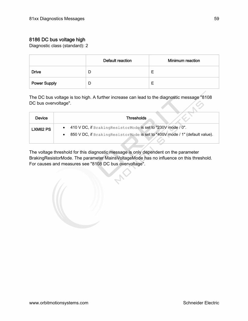
81xx Diagnostics Messages 59
www.orbitmotionsystems.com Schneider Electric
8186 DC bus voltage high
Diagnostic class (standard): 2
Default reaction Minimum reaction
Drive D E
Power Supply D E
The DC bus voltage is too high. A further increase can lead to the diagnostic message "8108
DC bus overvoltage".
Device Thresholds
LXM62 PS 410 V DC, if BrakingResistorMode is set to "230V mode / 0".
850 V DC, if BrakingResistorMode is set to "400V mode / 1" (default value).
The voltage threshold for this diagnostic message is only dependent on the parameter
BrakingResistorMode. The parameter MainsVoltageMode has no influence on this threshold.
For causes and measures see "8108 DC bus overvoltage".

82xx Diagnostics Messages 60
Schneider Electric
8204 Program cannot be loaded
Diagnostic class (standard): 3
Unable to load the IEC program.
Additional information on how to limit errors is stored in the DiagExtCode or the ext. diagnostic
in the message logger.
Ext. diagnostic Meaning
prog
xhhhhhhhh
IEC program code is too big
bad version The IEC program is not compatible with the PacDrive controller firmware (V00.10.00
or higher)
data
xhhhhhhhh
IEC data area is too large -> adjust number of data segments
ret xhhhhhhhh The retain area is too large
DOWNLOAD Unable to load and prepare the IEC program.
..
miscellaneous
Other data errors
Cause of “data xhhhhhhhh”:
A project was developed for an older version of the PacDrive controller firmware. In this project,
the number of data segments is greater than two (e.g. three). If you now transfer the program to
the controller, Logic Builder will display the following message after the transfer is complete:
"IEC program cannot be loaded!"
If this happens, reduce the number of data segments to two and transfer the project to
the controller again after the conversion process is complete.
Cause of “DOWNLOAD”:
A subsequent error is involved in this case.
Refer to the previous diagnostic message (e.g. 8312 "Parameter relocation failed").
There is no IEC program in the PacDrive controller or the IEC program is incompatible.
Transfer the IEC program again using Logic Builder.
The IEC program code, IEC data area or IEC retain area in the PacDrive controller is too
large.
See DiagExtCode.
Adjust project.
The setting in EPAS > Project > Options > Compilation options in the item "Number of
Data Segments" is less than 2 (DiagExtCode = ret xhhhhhhhh).
Increase the number of data segments.
8205 Impermissible parameter value
Diagnostic class (standard): 3

82xx Diagnostics Messages 61
www.orbitmotionsystems.com Schneider Electric
A parameter has an impermissible value. The DiagExtMsg parameter in the PLC configuration
or message logger can be used to determine the logical address of the parameter that contains
an impermissible value. Therefore an assignment to the PLC configuration is possible.
l=0Bxx0004; this means that a too small or too large value has been entered into the
virtual encoder for the Acceleration.
Enter a valid value for the acceleration.
l=03xx0025; this means the J_Load in the PLC configuration is too large.
Enter a valid value for J_Load.
l=01010004; this means the P_Gateway in PLC configuration does not match the
IP_SubNetMask.
Consider the conventions of the IP address terms.
8209 last boot failed
Diagnostic class (standard): 3
A drop in the control voltage of the PacDrive controller, a reset of the PacDrive controller or a
fatal error occurred in the last boot procedure. Use DiagExtMsg to localize the problem.
While booting, the PacDrive controller logs the individual phases in the NvRam. If this results in
a fatal error (Error LED is ON constantly), then the next boot is only with the basic configuration
and the diagnosis message 8209 is triggered.
NOTE: If the PacDrive controller is started in minimal boot mode, the configuration and the PLC
configuration parameters will be set to their default values.
NOTE: The next startup will occur in normal boot mode.
If this does not happen, the default configuration will used for the next startup, and the process
will be repeated ... !
DiagExtMsg Meaning
1 Boot procedure begins before kernel initialization
2 Kernel initialization complete; FTP server priority adjusted; Time Slicing switched on;
System clock; No. Tick per second defined Tick per second determined
3 Init logger and NvRam complete; interrupts blocked
31 Before ScanDisk
4 Diag created, messages sent, before ObjectContr new
10 Begin Constructor ObjVerObjektContr; Tasklock active
11 Config and Par file read
12 Config file evaluated, generate before objects

82xx Diagnostics Messages 62
www.orbitmotionsystems.com Schneider Electric
13 Generate after objects
14 Set after CycleTime
15 After init of Moni.Max, LogGeb, VirtGeb, PhyGeb, construction of RTP before filling in
indication table
16 Set after parameter
17 After Sercos run-up
18 After runtime system start
19 After RTP start, before program load
20 After program load
5 After ObjectContr new
6 After axis release, before WatchDogEin
RAM <
32MB
Insufficient RAM in the PacDrive controller
Procedure:
Logic Builder connection with TCP/IP
Read and evaluate message logger (important DiagExtMsg!)
The DiagExtMsg can be used to read which phase of the boot procedure was executed
correctly the last time.
The FC_SysReset() function was called, although the boot procedure of the PacDrive
controller was not yet complete.
Use the FC_GetPacDriveBootState() function to make sure that the PacDrive controller
has stopped the boot procedure before you use the FC_SysReset() function.
DiagExtMsg = 19: program error; that is, the application is incorrect.
Overwrite the application on the PacDrive controller by transferring a project (dummy)
with the default configuration.
Check your program and send an error-free application to the PacDrive controller.
DiagExtMsg is not 19.
Contact your responsible contact partner.
The PacDrive controller was booted twice in quick succession. This may have been
caused by pressing the reset button twice or a drop in the control voltage.
Check the control voltage (also refer to the technical data).
Insufficient RAM in the PacDrive controller for the project (DiagExtMsg=out of memory).

82xx Diagnostics Messages 63
www.orbitmotionsystems.com Schneider Electric
Meaning:
A memory requirement could not be executed. Memory is required when booting, resetting the
task, calling up system function blocks, setting/reading parameters, establishing/terminating an
FTP connection, transferring data (remote device), communicating with Logic Builder, and
establishing/terminating a Telnet connection and communicating with Telnet.
Reduce configuration.
RamDiskSize must be decreased.
Reduce number of tasks.
Apply a PacDrive controller that has more RAM.

83xx Diagnostics Messages 64
Schneider Electric
8300 Program divide by zero
Diagnostic class (standard): 3
A division by zero should be executed in the program.
NOTE: The division by "zero" is defined for REAL and LREAL and hence does not generate the
8300 "Program division by zero" diagnosis message.
The divisor was zero in a division function.
Compensate for division by zero in the program.
Check the number range
8301 coprocessor segment overflow
Diagnostic class (standard): 3
A system error has occurred.
An internal system error has occurred.
Please contact your Schneider Electric contact person.
8302 stack error
Diagnostic class (standard): 3
A system error has occurred.
An internal system error has occurred.
Please contact your Schneider Electric contact person.
8303 general protection error
Diagnostic class (standard): 3
A system error has occurred.
An internal system error has occurred.
Please contact your Schneider Electric contact person.
8304 coprocessor error
Diagnostic class (standard): 3
A system error has occurred.
An internal system error has occurred.
Please contact your Schneider Electric contact person.
8305 memory limit exceeded
Diagnostic class (standard): 3
A system error has occurred.
An internal system error has occurred.
Please contact your Schneider Electric contact person.
8306 arithmetic overflow
Diagnostic class (standard): 3
A system error has occurred.
An internal system error has occurred.

83xx Diagnostics Messages 65
www.orbitmotionsystems.com Schneider Electric
Please contact your Schneider Electric contact person.
8307 double execution error
Diagnostic class (standard): 3
A system error has occurred.
An internal system error has occurred.
Please contact your Schneider Electric contact person.
8308 invalid task state segment
Diagnostic class (standard): 3
A system error has occurred.
An internal system error has occurred.
Please contact your Schneider Electric contact person.
8309 no memory segment
Diagnostic class (standard): 3
A system error has occurred.
An internal system error has occurred.
Please contact your Schneider Electric contact person.
8310 faulty memory segment adjustment
Diagnostic class (standard): 3
A system error has occurred.
An internal system error has occurred.
Please contact your Schneider Electric contact person.
8311 coprocessor division error
Diagnostic class (standard): 3
A system error has occurred.
An internal system error has occurred.
Please contact your Schneider Electric contact person.
8312 Parameter relocation failed
Diagnostic class (standard): 3
A system error has occurred.
An internal system error has occurred.
Please contact your Schneider Electric representative.
8313 excessive cycle time overrun
Diagnostic class (standard): 3
The excessive cycle time error is monitored by the system. The IEC task is stops immediately, if
a fatal error occurs because of a cycle time overrun. Stopping the task is controlled by the
system, not by the task itself so it is done without taking care of the current or following

83xx Diagnostics Messages 66
www.orbitmotionsystems.com Schneider Electric
operations. Therefore, it can not be ruled out, that the task is performing e.g. a read/write
operation on the file system and so blocks another system resource exclusively. This resource
is not released, when the task is stopped. If other tasks try to access this resource subsequent
errors may occur.
The fatal cycle error of an IEC task is reported when the 10x cycle time (see task configuration)
is exceeded.
The task then receives an error status. You can quit the diagnosis message by resetting the IEC
program but the error itself can be solved only by resetting the controller (Online > Reset
PacDrive controller). The cycle time monitoring of the IEC task refers to the load parameter that
is displayed in the IEC task expansion object in the PLC Configuration.
The processing time of a parameter or system functional block that is being called is
taking "too long".
Perform a reset of the the controller, as soon as possible.
Check program (e.g. access to SERCOS Parameter or FC_WaitTime() function).
The time interval in the task configuration is too short.
Increase the time interval in the task configuration.
If possible, use critical activities in new/another task.
8316 NvRam data not valid
Diagnostic class (standard): 2
The NvRam lost the data. This means that the data in the message logger and the variable
values are invalid. In this case the message logger is automatically deleted by the system.
An internal system error has occurred.
Replace PacDrive controller.
8317 Program cycle time overrun
Diagnostic class (standard): 2
A cycle time error has been found. This error is triggered when the cycle time is exceeded by
more than one system clock tick (default value for a system clock tick is 250 µs). The
DiagExtMsg shows the "current cycle time" / "cycle time from the task configuration" in ms.
8318 Program calculated profile deleted
Diagnostic class (standard): 3
An attempt was made to calculate a profile (e.g. FC_CamMasterStart() ) that is just being
deleted with the function FC_ProfilDelete(). DiagExtMsg displays the profile ID in hexadecimal
form (e.g. Prof=10010000).
Program error: The profile to be calculated has been deleted too early or the wrong
profile has been deleted.
Check the program.
Program error: asynchronously running high-priority externally event-controlled tasks
were used.
Synchronize externally event-controlled task to real-time process.
8320 bad array access (check)

83xx Diagnostics Messages 67
www.orbitmotionsystems.com Schneider Electric
Diagnostic class (standard): 3
An array access error in the user program was found by the Check.lib. The message logger call
hierarchy function can be used to "backtrace" the function block call or nesting.
While accessing an array, the area limits of that array were violated in the user program.
Check the user program.
8321 division by zero (check)
Diagnostic class (standard): 3
In the user program a division by zero was found by the Check.lib. The message logger call
hierarchy function can be used to "backtrace" the function block call or nesting.
A division by zero should executed in the program.
Compensate for division by zero in the program.
Check the number range.
8322 exception by IEC task
Diagnostic class (standard): 3
If the task detects a fatal error (e.g. access error via pointer), it triggers a diagnosis message.
The message logger call hierarchy function can be used to "backtrace" the function block call or
nesting
8323 string too long
Diagnostic class (standard): 3
The maximum string length (255) was found in the IEC user program by the Check.lib. The
message logger call hierarchy function can be used to "backtrace" the function block call or
nesting.
The maximum string length in the user program was exceeded.
Check the user program.
8324 UPS failure detected
Diagnostic class (standard): 3
There is an internal error in the UPS.
The battery of the UPS is empty.
Charge the battery.
The power supply of the UPS is working, but the “ON/OFF” input of the UPS is set to
OFF.
If the voltage supply is correct, then the “ON/OFF” input must be ON in order to use the
UPS.
An UPS Object is specified in the PLC configuration, but no UPS is connected.
Check the IEC program.
An internal UPS error has occurred.
Check the program.
Ext. diagnosis: "PIC fail" or "State = 5"
An internal PIC controller error has occurred.

83xx Diagnostics Messages 68
www.orbitmotionsystems.com Schneider Electric
Contact your responsible contact partner.
8325 File corrupt
Diagnostic class (standard): 3
A problem (file non existent or CRC error) occured while reading the retain file. The retain file
will be read by the flash disk while the PacDrive controller boots if the Enable parameter of the
UPS object is set to "External / 1".
An UPS Object is specified in the PLC configuration, but no UPS is connected.
Check the IEC program.
The UPS is not functioning properly.
Check the UPS.
8326 Program function not supported
Diagnostic class (standard): 3
A function has been called that is not supported by the PacDrive system. Further information on
Object type and instance are displayed in the message logger. The DiagExtMsg also provides
information on the error cause.
A division by zero should executed in the IEC program.
Check the hardware version with the help of the nameplate.
8327 CamTrack invalid PositionSource
Diagnostic class (standard): 2
The CamTrack in the PositionSource parameter contains an invalid value.
The symbolic name of a logical encoder or an axis was not specified in the
PositionSource parameter.
Check the value in the PositionSource parameter.
8328 CamTrack invalid Destination
Diagnostic class (standard): 2
The CamTrack in the Destination parameter contains an invalid value.
The Destination parameter was specified either without the symbolic name of an output
group or with "none".
If an IEC task detects a fatal error (e.g. access error using pointer), it triggers a
diagnosis message.
8329 CamTrack invalid Bitnumber
Diagnostic class (standard): 2
The CamTrack in the Bitno parameter contains an invalid value.
An invalid bit number was specified in the Bitno parameter.
Check the IEC program.
8330 Program master job not executable
Diagnostic class (standard): 3

83xx Diagnostics Messages 69
www.orbitmotionsystems.com Schneider Electric
This diagnosis message is triggered if the system is unable to process the master positioning
job of an axis even though no errors were detected by the job parameter area checks (e.g. error
in the precalculation of generator data).
The error is shown in the extended diagnosis message as "GT=XXX,MJId=YYY". XXX indicates
the generator type while YYY indicates the Master-JobId of the job that caused the problem.
Generator type:
0 -> CAM
1 -> POS
Internal calculation error.
Contact your responsible contact partner.
8331 Licensing
Diagnostic class (standard): 3
This diagnosis message will be triggered by the license server of the PacDrive controller if a
function block is used without a sufficient number of points. The 8331 “Licensing” error (which
can be acknowledged) will be triggered first so as to notify the user that the remaining run time
of the system is only six hours. More information on the object type and the instance is
displayed in the message logger. After this period of time runs out a high-priority error is
triggered that cannot be acknowledged. After a few minutes (about 5 min.), the SERCOS bus is
shut down, making any further use of the affected controller impossible.
The number of license points on the compact flash card of the PacDrive controller is not
sufficient.
Check the number of required license points with the parameter for licensing in the PLC
configuration.
Also refer to 8332 Licensing.
8332 Licensing
Diagnostic class (standard): 3
This diagnosis message will be triggered by the license server of the PacDrive controller if a
function block is used without a sufficient number of points. The 8331 “Licensing” error (which
can be acknowledged) will be triggered first so as to notify the user that the remaining run time
of the system is only six hours. More information on the object type and the instance is
displayed in the message logger. The DiagExtCode also provides information on the error
cause. After a few minutes (about 5 min.), the SERCOS bus is shut down, making any further
use of the affected controller impossible.
The number of license points on the compact flash card of the PacDrive controller is not
sufficient.
Check the number of required license points with the parameter for licensing in the PLC
configuration.
Also refer to 8331 Licensing.
8333 EncoderNet receiving data not possible
Diagnosis class (standard): 3
In the encoder network a fatal error occurred when distributing the encoder position.

83xx Diagnostics Messages 70
www.orbitmotionsystems.com Schneider Electric
Ext. diagnosis: "Dupl. Obj."
Multiple initialization of object (SYN_DIN, SYN_DOUT).
-
Ext. diagnosis: "Int.Err=-xxx"
Internal error code.
-
Ext. diagnosis: "SyncLost"
Synchronization was lost while the object (SYN_DIN, SYN_DOUT) was active.
-
Ext. diagnosis: "No Data: xxx"
The number of data sets (xxx) that was not received sequentially exceeds the limit
specified in DataCycleErrorLimit.
-
Ext. diagnosis: "Send error"
Due to an internal mistake for 5 cycles no telegrams were dispatched.
-
8334 EncoderNet receiving data dist.detected
Diagnosis class (standard): 2
In the encoder network an error occurred when distributing the encoder position.
Ext. diagnosis: "No Data: xxx"
xxx data sets were not received sequentially. If more data sets are not received in a row
than specified in DataCycleErrorLimit, then the diagnosis message 8333 "EncoderNet
receiving data not possible" is triggered.
-
8335 EncoderNet synchronization not possible
Diagnostic class (standard): 3
Filter type 2 "Diagnostic messages"
A fatal error occurred in the encoder network when synchronizing the controller system clocks.
Ext. diagnostic: "Sync Init" (Object SYN_M or SYN_S)
The initialization of synchronization master or synchronization slave failed. The IP
address (SlaveIPAddress) of the sync. Module is assigned twice.
Check parameter SlaveIPAddress of the sync. modules in the synchronization master
PLC configuration.
Ext. diagnostic: "SercosPhase xxx"
The SERCOS loop is not in phase 4.
SERCOS bus in phase 4 "booted"
Ext. diagnostic: "Dupl. MasterID"
The set MasterID is already being used by another synchronization master who is in the
same network.
83xx Diagnostics Messages 71
www.orbitmotionsystems.com Schneider Electric
Change the MasterID.
Ext. diagnostic: “ProtVer xxx”
The synchronization master protocol version no longer matches the synchronization
slave protocol version.
Use compatible software versions for the controllers.
Contact your Schneider Electric contact person.
Ext. Diagnostic: "Ping Master"
The synchronization master failed to respond to a ping.
Check the Ethernet connection to the synchronization master.
Ext. Diagnostic "Dupl. Slave IP" (object SYN_MOD
The IP address (SlaveIPAddress) of the sync. Module is assigned twice.
Check parameter SlaveIPAddress of the sync. modules in the synchronization master
PLC configuration.
Ext. Diagnostic: "SlaveCycleTime"
The SlaveCycleTime is not a multiple of the SERCOS cycle time.
parameter SlaveCycleTime or adjust the SERCOS cycle time.
Ext. diagnostic: "Wrong config" (object SYN_MOD)
The activated synchronization slave is not configured properly or is not responding.
Check the configuration of the synchronization slave (e.g. same CycleTime).
Check TCP/IP connection between synchronization master and synchronization slave.
Ext. diagnostic: "Wrong config" (object SYN_S)
The SERCOS cycle times differ between synchronization master and synchronization
slave or the synchronization slave-configuration cannot be transmitted.
Adjust the CycleTime parameter of the synchronization master and/or synchronization
slaves.
Ext. diagnostic: "Wrong State"
The activated synchronization slave is in an error state.
Acknowledge the error in the synchronization slave.
Ext. diagnostic: "No DataOut"
No Sync. Encoder output has been configured or activated.
Check the PLC configuration.
Check the TCP/IP connection synchronization master to synchronization slave. Activate
endocer output (parameter Enable).
Ext. diagnostic: "No Module"
No Sync. module and no Sync. encoder input are configured or enabled.

83xx Diagnostics Messages 72
www.orbitmotionsystems.com Schneider Electric
Check the PLC configuration.
Check the TCP/IP connection synchronization master to synchronization slave. Module
or Sync. Activate encoder output (sync. module parameter Enable or sync. encoder
input parameter Enable).
Ext. diagnostic: "Sync Err"
The synchronization slaves are unable to synchronize with the synchronization master.
The Ethernet (see parameter SyncQuality) and / or the CPU load (see parameter
AvailableLoad) is too high.
Check the Ethernet connection.
Optimize the IEC project to reduce the CPU load.
Ext. diagnostic: "No Sync: xxx"
The number of sequential synchronization telegrams (xxx) which were not received
exceeded the number specified in SlaveCycleErrorLimit. The Ethernet (see parameter
SyncQuality) and / or the CPU load (see parameter AvailableLoad) is too high.
Check the Ethernet connection.
Optimize the IEC project to reduce the CPU load.
Increase SlaveCycleErrorLimit .
Ext. diagnostic: "DataReady Err"
The Sync. Encoder outputs cannot configure sync. encoder inputs or a data error
occurred during normal operation.
Check parameter DiagCode of sync. modules for more detailed information on the error
source.
Ext. diagnostic: "DataEnable Err"
Either the sync. encoder outputs are unable to configure the sync. encoder inputs or a
data error has occurred while the system is running. Encoder outputs and sync. encoder
inputs are ready for the data exchange.
Check parameter DiagCode of sync. modules for more detailed information on the error
source.
Ext. diagnostic: "Wrong IP Add"
The parameter SlaveIPAddress is not set.
Contact your Schneider Electric contact person.
Ext. diagnostic: "Wrong IP Add"
Internal error code
Contact your Schneider Electric contact person.
Ext. diagnostic: "Sync Err Wnd"
The synchronization has been interrupted due to excessive telegram delays.
Ethernet data communication too high.

83xx Diagnostics Messages 73
www.orbitmotionsystems.com Schneider Electric
Ext. diagnostic: "Sync Err LCyc"
The synchronization has been interrupted due to excessive telegram failures.
Ext. diagnostic: "Sync Err CtrlM"
The synchronization master has received an diagnostic message from a slave reporting a
severe communication error.
Ext. diagnostic: "Sync Err CtrlS"
The synchronization slave has received an diagnostic message from the master reporting a
severe communication error.
Ext. diagnostic: "Sync Err CtrlN"
The synchronization module has received an diagnostic message from the corresponding
synchronization slave reporting a severe communication error and was unable to read more
detailed diagnostic information.
Ext. diagnostic: "Sync TimeoutM"
The synchronization master has determined a timeout for establishing synchronization (> 5min).
Ext. diagnostic: "Sync TimeoutS"
The synchronization slave has determined a timeout for establishing synchronization (> 5min).
8336 EncoderNet Sync. disturbance detected
from V00.22.00
Diagnosis class (standard): 2
An error occurred in the encoder network when synchronizing the controller system clocks.
Ext. diagnosis: "No Sync: xxx"
More than half of the synchronization telegrams (xxx) specified in SlaveCycleErrorLimit
have not been received sequentially. If more synchronization telegrams are not received
in a row than specified in SlaveCycleErrorLimit, then the diagnosis message 8335
"EncoderNet Sync. disturbance detected" is triggered.
-
8337 Parameter DynIECData value too high
Diagnostic class (standard): 3
Filter type 1 "general system messages"
The dynamic memory area, which was specified with the DynIECDataSize parameter, could not
be reserved due to insufficient memory (RAM). During IEC program start, a check will be
performed to determine if there is at least 4 MB of available memory after the dynamic memory
area is reserved (also see the Memoryfreeparameter).
The dynamic memory area to be reserved is too high.
Reduce the value of the parameter DynIECDataSize.

83xx Diagnostics Messages 74
www.orbitmotionsystems.com Schneider Electric
8338 UPS battery not charged
Diagnostic class (standard): 3
The battery is not sufficiently charged.
Ext. diagnosis: "State = 2"
The PacDrive controller has been switched off for too long.
Switch on the PacDrive controller.
The battery will be charged automatically when the PacDrive controller is on.
The UPS has been operating in the battery mode (State = 3) for an extended period.
Check the supply voltage.
Switch on the PacDrive controller if it is off.
The battery will be charged automatically when the PacDrive controller is on.
The battery capacity is insufficient due to aging.
Contact your responsible contact partner.
8339 UPS active - system temperature high
Diagnostic class (standard): 3
The temperature in the PacDrive controller is too high.
Ext. diagnosis: "State = 6"
Ambient temperature too high.
For further details, please refer to the technical data on the PacDrive controller (see
operating instructions).
8340 out of range (check)
Diagnostic class (standard): 3
reserved
8341 CamTrack invalid Position type
Diagnostic class (standard): 2
The CamTrack in the parameter PositionType contains an invalid value.
No valid position type (parameter PositionType) of the position source PositionSource)
has been entered.
Check the parameters PositionType and PositionSource

84xx Diagnostics Messages 75
Schneider Electric
8400 Program diagnosis message class 0
Diagnostic class (standard): 0
A diagnosis message from the program has been triggered with the FC_DiagMsgWrite()
function.
The error was triggered by the program.
See description of your program. It is possible to display an additional error text with the
FC_DiagMsgWrite() function.
8401 Program diagnosis message class 1
Diagnostic class (standard): 1
A diagnosis message from the program has been triggered with the FC_DiagMsgWrite()
function.
The error was triggered by the program.
See description of your program. It is possible to display an additional error text with the
FC_DiagMsgWrite() function.
8402 Program diagnosis message class 2
Diagnosis class (standard): 2
A diagnosis message from the program has been triggered with the FC_DiagMsgWrite()
function.
The error was triggered by the program.
See description of your program. It is possible to display an additional error text with the
FC_DiagMsgWrite() function.
8403 Program diagnosis message class 3
Diagnostic class (standard): 3
A diagnosis message from the program has been triggered with the FC_DiagMsgWrite()
function.
The error was triggered by the program.
See description of your program. It is possible to display an additional error text with the
FC_DiagMsgWrite() function.
8404 Program diagnosis message class 4
Diagnostic class (standard): 4
A diagnosis message from the program has been triggered with the FC_DiagMsgWrite()
function.
The error was triggered by the program.
See description of your program. It is possible to display an additional error text with the
FC_DiagMsgWrite() function.
8406 IEC diagnosis message class 1
Diagnostic class (standard): 1
A diagnostic message from the IEC program has been triggered by means of the
FC_DiagMsgWrite() function.

84xx Diagnostics Messages 76
www.orbitmotionsystems.com Schneider Electric
The error was triggered by the IEC program.
See description of your IEC program. It is possible to display an additional error text with
the FC_DiagMsgWrite() function.

85xx Diagnostics Messages 77
Schneider Electric
8501 SERCOS slave not found
Diagnostic class (standard): 3
The device, that was expected at the position (x), was not found.
Error when assigning the identification features.
Check the settings of the identification features (for example:
ConfiguredTopologyAddress)
A SERCOS slave listed in the PLC configuration cannot be found in the SERCOS bus.
SERCOS slave not present in the SERCOS bus.
Connect the SERCOS slave to the SERCOS bus or remove the SERCOS slave from the
PLC configuration or parameterize it as avirtual device
8502 SERCOS loop not closed
Diagnostic class (standard): 1
The SERCOS loop is not closed. The result was a longer interruption (>100 ms) of the ring.
You can check whether the interruption is still present using Light diode "bus err" and the
RingStatus parameter.
When the interruption has been eliminated and the SERCOS bus is at least in phase 2, the
source of the error can be narrowed down with the help of the SERCOS Firmware Assistenten
in the data view System diagnosis > SERCOS Configuration and SERCOS Topology.
Signal over the SERCOS fiberoptic conductor is incorrect.
Check the intensity setting in the PacDrive controller and on the servo amplifier.
Check wiring (see parameter RingStatus).
A device in the SERCOS loop is switched off or was reset.
Check the power supply (24 V) of the device.
Switch on the device.
8503 SERCOS service channel error detected
Diagnostic class (standard): 3
A transfer error has occurred in the SERCOS bus during operation. Additional information will
be stored in DiagExtMsg.
DiagExtMsg Meaning
A BBBBB e
CCCCC
For example:
R S0057 e
1001
W P1039
This message is always the first message. In order to enable a better diagnosis, it
can be supplemented by further messages with the same error number and one of
the following DiagExtMsg.
Here, it is indicated, which parameter access leads to which error.
A Type of access
R = read
85xx Diagnostics Messages 78
www.orbitmotionsystems.com Schneider Electric
e20006
C S1024 e -
445
W = write
C = command execution
BBBBB Parameter number, with wich the error occurred. The first position
indicates, whether it is a standard ("S") or a manufacturer-specific ("P")
SERCOS-parameter. If it is an EIDN, an additional error message is sent
(see DiagExtMsg = IDN.SI.SE).
CCCCC error code of the occurred error The possible error codes are given in the
following tables.
IDN.SI.SE
For example:
S1300.0.12
P1039.1.3
If the IDN is an extended IDN (EIDN), the display by the structure instance (SI) and
the structure element (SE) of the IDN is too long to be displayed in the regular error
message. In this case, the complete IDN is displayed in this second diagnostic
message.
Will only be dropped from SoMM V1.35.x.x. and above.
TopoAdr=xxx If the SERCOS-slave is a not configured slave (the real slave is not assigned to any
device in the PLC Configuration), the topology address (position in the SERCOS-bus)
is output via this additional message.
Diag. Code 8503 / external diag. Code W P1078 e 700C
MotorCommutationControl has been started during an InternalDeviceState unequal to:
InternalDeviceState=0xA1 or InternalDeviceState=0xE0
MotorCommutationControl can only be started under the following conditions:
InternalDeviceState=0xA1 or InternalDeviceState=0xE0
The parameter EncoderGearIn (or EncoderGearOut) is unequal to "1" or
EncoderDirection is set to "inverted / 0".
Saving the motor commutation into the motor nameplate is not possible.
Diag. Code 8503 / external diag. Code W P0623 e 7007
The MotorIdentification parameter has been set to Motor without nameplate / 2.
Motors without nameplates are not yet supported.
Diag. Code 8503 / external diag. Code W P1068 e 700C
The parameter VoltageFeedForwardMode has been set to Dynamic command action / 2
or Dynamic behavior of the control loop / 3.
The parameter settings are supported as of FPGA version 01/06/xx/xx.
Diag. Code 8503 / W P1040 e 7007 or W P 1040 e 7006
The power stage frequency has been set to an invalid value via
FC_PowerStageFrequencySet.

85xx Diagnostics Messages 79
www.orbitmotionsystems.com Schneider Electric
Select a valid power stage frequency.
Diag. Code 8503 / W P1023 e 700B
MotorTemperatureMonitoring has been changed at an InternalDeviceState greater than
or equal to 0xB1
The MotorTemperatureMonitoring can only be changed if the InternalDeviceState is
smaller than 0xB1.
Diag. Code 8503 / external diag. Code W S1040 e 7005
The sercos-adress could not be written. The controller only writes the SERCOS-address
during the phase run-up, if there are several SERCOS-participants with the same
SERCOS-address and their parameter IdentificationMode is set to a value unequal to
"SercosAddress / 4". This occurs for instance with TM5NS31 and TM5CSLCx00FS, if
the SERCOS-address is set to a value unequal to 0 by the adress selection switches.
Set the SERCOS address selection switches to 0 for all TM5NS31 and TM5CSLCx00FS
that shall not be identified via the IdentificationMode "SercosAddress / 4".
Also refer to Error codes of the SERCOS parameter channel (service channel).
Error messages from SERCOS slaves
All four-digit error codes identify error messages which are reported to the master by SERCOS
slave. In this case, the error codes are standard SERCOS error codes.
Fehlercode Description
0x0nnn General error
0x0000 No error in the service channel
0x0001 Service channel not open
0x0009 Invalid access to closing the service channel
0x1nnn Element 1 (Identification number)
0x1001 No valid IDN
0x1009 Invalid access to element 1
0x2nnn Element 2 (Name)
0x2001 No name
0x2002 Name transmission too short
0x2003 Name transmission too long
0x2004 Name cannot be changed (read only)
0x2005 Name is write-protected at this time
0x3nnn Element 3 (Attribute)

85xx Diagnostics Messages 80
www.orbitmotionsystems.com Schneider Electric
0x3002 Attribute transmission too short
0x3003 Attribute transmission too long
0x3004 Attribute cannot be changed (read only)
0x3005 Attribute is write-protected at this time
0x4nnn Element 4 (Unit)
0x4001 No units
0x4002 Unit transmission too short
0x4003 Unit transmission too long
0x4004 Unit cannot be changed (read only)
0x4005 Unit is write-protected at this time
0x5nnn Element 5 (Minimum input value)
0x5001 No minimum input value
0x5002 Minimum input value transmission too short
0x5003 Minimum input value transmission too long
0x5004 Minimum input value cannot be changed (read only)
0x5005 Minimum input value is write-protected at this time
0x6nnn Element 6 (Maximum input value)
0x6001 No maximum input value
0x6002 Maximum input value transmission too short
0x6003 Maximum input value transmission too long
0x6004 Maximum input value cannot be changed (read only)
0x6005 Maximum input value is write-protected at this time
0x7nnn Element 7 (Operation data)
0x7002 Operation data transmission too short
0x7003 Operation data transmission too long
0x7004 Operation data cannot be changed (read only)
0x7005 Operation data is write-protected at this communication phase
0x7006 Operation data is smaller than the minimum input value
0x7007 Operation data is greater than the maximum input value
0x7008 Invalid operation data:
Configured IDN will not be supported, invalid bit number or bit combination
0x7009 Operation data write protected by a password

85xx Diagnostics Messages 81
www.orbitmotionsystems.com Schneider Electric
0x700A Operation data is write protected, it is configured cyclically. (IDN is configured in
the MDT or AT. Therefore writing via the service channel is not allowed).
0x700B Invalid indirect addressing: (e.g., data container, list handling)
0x700C Operation data is write protected, due to other settings (for instance operating
mode, subdevice is activated, etc.).
0x700D Invalid floating point number
0x700E Operation data is write protected at parameterization level
0x700F Operation data is write protected at operating level
0x7010 Procedure command already active
0x7011 Procedure command not interruptible
0x7012 Procedure command at this time not executable (e.g., in this phase the
procedure command can not be activated).
0x7013 Procedure command not executable (invalid or false parameters)
0x7014 The received current length of parameter with variable length does not match to
expectation
0x71nn Segmentwise SVC access for parameters with variable length
0x7101 IDN in S-0-0394 not valid
0x7102 Empty list in S-0-0397 not allowed for write access
0x7103 Maximum length of the list in S -0-0394 is exceeded by take-over of the list
segment.
0x7104 Read access only: The length of the list segment as of the list index exceeds the
cur-rent length of the list in S -0-0394.
0x7105 IDN in S-0-0394 is write protected
0x7106 Operation data in list segment is smaller than the minimum input value.
0x7107 Operation data in list segment is greater than the maximum input value.
0x7108 Invalid list index in S-0-0395
0x7109 Parameter in IDN S-0-0394 does not have variable length
0x710A IDN S-0-0397 not permitted as data in S-0-0394
0xD000 No error
0xD001 Service channel (temporarily) not available
0xD002 Service channel engaged by an application
0xD003 Service channel busy, slave is processing previous request

85xx Diagnostics Messages 82
www.orbitmotionsystems.com Schneider Electric
0xD004 Sercos Slave not reachable
0xD005 Service channel transaction aborted
0xD006 Writing this element is not support by the service channel
Error messages from SERCOS Master
If errors are recognized by the SERCOS Master, they are specified as a five-digit hexadecimal
value or a negative numeric value.
Fehlercode Description
20001 SVC: New request with higher priority during active internal request.
20002 SVC: New internal request during active internal request.
20003 SVC: Transmission canceled by an other function call with higher priority
20004 SVC: New transmission requested but MBusy is not set
20005 SVC: Invalid state: AHS != MHS during set BusyAT
20006 SVC: Timeout due to slave has not set the BusyAT flag
20007 SVC: Timeout due to slave has set BusyAT flag too long
20008 SVC: Write with unsupported element (allowed 1 or 7)
20009 SVC: Write with data length = zero
-1 other error
-431 Service request error (e.g. timeout)
-445 Service timeout
-467 Internal state machine error
Error messages from SERCOS Master
8504 SERCOS read cycle overflow
Diagnostic class (standard): 3

85xx Diagnostics Messages 83
www.orbitmotionsystems.com Schneider Electric
The transfer of the actual position of the axes (servo amplifiers) to the PacDrive controller
occurred too late. The actual values of the next SERCOS cycle have already been read. The
actual velocity for the program may not be correct.
SERCOS bus is overloaded.
Increase CycleTime parameter in the PLC Configuration.
A device in the SERCOS loop is switched off or was reset.
Switch on SERCOS slave.
8505 SERCOS Master comm.disturbance detected
Diagnosis class (Default): 2
A check sum error on the SERCOS bus has been detected. The data (target and actual
position) of the last cycle are used again.
EMC problems.
Check the wiring.
8506 SERCOS Master comm. not possible
Diagnosis class (Default): 3
SERCOS communication interrupted, because no link exists anymore on both ports.
Wiring error (cable separated).
Check wiring.
SERCOS slave failed after the controller.
Check device and reset if necessary.
SERCOS communication interrupted, because more than the allowed numbers of DT's have
failed sequentially.
Wiring error (cable separated).
Check wiring.
A SERCOS slave has failed.
Check device and reset if necessary.
In two consecutive cycles, an error was detected on the SERCOS bus while receiving data. The
SERCOS bus was shut down.

85xx Diagnostics Messages 84
www.orbitmotionsystems.com Schneider Electric
CAUTION
POSITION LOSS DUE TO SERIOUS SERCOS BUS ERROR!
Loss of position of the axes and physical encoders (SinCos, incremental encoder) is
possible as a consequence of error acknowledgement of diagnostic message 8506
"SERCOS Master communication not possible" without restarting the controller.
Acknowledge the diagnosis message only after re-initialization or homing of the system
has been ensured by the program.
The capability to acknowledge the diagnostic message can be switched off with the
function FC_DiagNoQuitSet().
If necessary, use the functions FC_SysReset() or FC_PrgResetAndStart().
Failure to follow these instructions can result in injury or equipment damage.
NOTICE
CONNECTION TO CONTROLLER INTERRUPTED
The diagnosis message 8112 "SERCOS telegram invalid" is not reported in the system
because the SERCOS slave cannot report the diagnosis code error via the SERCOS
bus in case of an error.
In this case, diagnosis code 8506 "SERCOS Master communication not possible" is reported.
Failure to follow these instructions can result in equipment damage.
8507 SERCOS write cycle overflow
Diagnosis class (Default): 3
The transfer of the target position to the SERCOS bus occurred too late. The last target
positions may have been transferred twice. This results in at velocity jump in the drives (see
parameter RTPWriteRes)
The real-time process is overloaded.
Reduce the number of objects with real-time tasks (e.g. virtual axes, virtual
encoders, logical encoders, sum encoders, ...).
8508 SERCOS run-up not possible
Diagnostic class (Default): 3
At least one sercos slave does not react on time after the phase change to phase 3.
General software error in one of the sercos slaves.

85xx Diagnostics Messages 85
www.orbitmotionsystems.com Schneider Electric
Reset the sercos slave and start sercos run-up again.
No telegrams were received in phase 0, the ring is not closed.
Wiring error (cable separated).
Check wiring.
Sercos slave failed after the controller.
Check device and reset if necessary.
ExtDiagMsg "C_Time=20000"
An error occurred during the parameter transfer for the configuration of the sercos
timing. e.g.: one set ProducerCycleTime of a sercos I/O device is not supported by the
device.
8509 SERCOS slave SW not supported
Diagnostic class (standard): 3
The firmware version of the SERCOS slave is incorrect.
The firmware version of the SERCOS slaves is higher than the firmware version of the
PacDrive controller in the first 4 positions.
Increase the CycleTime parameter in the PLC configuration.
Ext. diagnosis = Vxx.yy.zz BLD
The SERCOS slave is in bootloader mode. The version of the Bootloader is shown in the
message logger under Ext. Diagnosis. The SERCOS slave can also be found using the
information on the object and instance provided in the message logger.
Reduce the number of objects with real-time tasks (e.g. virtual axes, virtual encoders,
logical encoders, sum encoders, ...).
Reset the SERCOS slaves.
Acknowledge the diagnosis message.
The SERCOS bus is running up in phase 4.
8510 SERCOS Interrupt lost
Diagnosis class (Default): 3
The interruption of the SERCOS bus has not occurred for at least two cycle times. This
diagnostic message normally occurs together with other diagnostic messages (8504 SERCOS
Read cycle overrun, 8507 SERCOS Write cycle overrun).
Wiring error: The fiber-optic conductor of the SERCOS bus is damaged.
Check the intensity setting for the SERCOS interface.
A SERCOS slave failed.
Check the SERCOS slave.
8511 CPU time overflow
Diagnosis class (Default): 3
The real-time process is overloaded (CycleLoad >95 %). The DiagExtMsg parameter displays
the measured load as ‘Load = xxx%’ with xxx indicating the load in %.
NOTE: After detecting the error, the actual and target values for the encoders, generators and
axes will no longer be processed in the real-time process. As a result, the “target and actual
values” parameter of the axes will show invalid values.

85xx Diagnostics Messages 86
www.orbitmotionsystems.com Schneider Electric
Too many objects have been entered into the PLC configuration.
Increase the CycleTime parameter of the SERCOS interface in the PLC configuration.
8512 SERCOS wrong device type
Diagnosis class (Default): 3
The device type of the SERCOS slave found on position (x) does not match the expected type
(type). (PD3)
Error when assigning the identification features.
Check the settings of the identification features (for example:
ConfiguredTopologyAddress).
Ext. Diagnostic NoPS connected
Unable to assign a power supply to the drive. (see parameter ConfiguredPowerSupply
and PowerSupply)
The parameter ConfiguredPowerSupply is empty, but no PowerSupply (for example,
LXM62PSM) is contained in the project.
Add an appropriate PowerSupply to the project (LXM62PSM).
The parameter ConfiguredPowerSupply contains a name which does not comply with a
PowerSupply (for example, LXM62PSM) in the project.
Add another PowerSupply to the project with the correct name or enter the name of a
projected PowerSupply into the parameter ConfiguredPowerSupply.
When starting up the SERCOS bus in Phase 2, the type of the detected SERCOS slave will be
checked with the slave that is entered in the PLC configuration. The interrupt of the SERCOS
bus has not been received in at least twice the cycle time . The type detected will be entered in
the extended diagnosis.
8517 SERCOS addressing not unique
Diagnostic class (standard): 3
It was not possible to effect a clear allocation of the slave to a real SERCOS slave.
Several real slaves with matching identification features were found.
Check parameter IdentificationMode and the corresponding identification feature.
8518 SERCOS too many real slaves
Diagnostic class (standard): 3
The number of real SERCOS slaves is too high.
Ext. diagnosis: HW <maximum number of SERCOS slaves on the controller>/<Number of
configured SERCOS slaves>
Limited by the controller type:
Before exiting the SERCOS phase 0, the number of configured real SERCOS slaves in
the PLC configuration will be checked. The number must be smaller or equal to the
licensed number for the PacDrive controller. If this value is exceeded, the run-up will be

85xx Diagnostics Messages 87
www.orbitmotionsystems.com Schneider Electric
canceled. The extended diagnosis shows the licensed and the configured number
together with the "HW" prefix. In the controller firmware, power supplies (LXM62 PS) are
no longer counted as SERCOS slaves.
Check the PacDrive controller type by referring to the nameplate.

86xx Diagnostics Messages 88
Schneider Electric
8600 Master Encoder comm. not possible
Diagnostic class (standard): 3
An error has occurred while exchanging data with the SinCos master encoder via the serial
interface of the encoder.
NOTICE
INITPOSITION AND ENCODERPOSITION ARE POSSIBLY INCORRECT.
Reset PacDrive controller after you have removed the error.
Failure to follow these instructions can result in equipment damage.
Wiring error: The encoder cable is not plugged in correctly or is defective.
Check the encoder cable and replace if necessary.
Reset the PacDrive Controller.
Data is exchanged using the encoder's serial interface during the functions
FC_PhyEndGetPosition(), FC_PhyEncResetEncoder() and FC_PhyEndSetPosition().
The actual data exchange is performed by the system task
(TASK_TYPE_PHY_ENC_JOB_Server). If the function is active, this task must query the
serial interface on a regular basis (usually<2ms). Insufficiently allocated processing time
may result in data loss.
The TASK_TYPE_PHY_ENC_JOB_Server system task runs at IEC priority 5 (same as
system priority 225). If the above functions in the tasks are called with a priority of 1 to 4,
this problem may result when the processing requirements are too high.
Check the cycle time.
Reset the PacDrive Controller.
Example:
The FC_PhyEncGetPosition() function is triggered from a task with a priority of 4. The task
normally requires 2.5ms for processing. Increase the priority of the system task from 225 (or
priority 5) to 224 (or priority 4) for example.
FC_SetTaskPriority(lTaskType:=TASK_TYP_PHY_ENC_JOB_Server, lPriority:=224);
Hardware error: The SinCos encoder is defective.
Replace the encoder.
Reset the PacDrive Controller.
Hardware error: The SinCos encoder is defective.
Replace the controller.
8601 Master Encoder signal out of range
Diagnostic class (standard): 3
Unable to receive analog data from the SinCos master encoder.

86xx Diagnostics Messages 89
www.orbitmotionsystems.com Schneider Electric
NOTE: Hardware encoder error! Reset the PacDrive controller. Acknowledge the diagnosis
message only after re-initialization or homing of the system has been ensured by the program. If
necessary, use the functions FC_SysReset() or FC_PrgResetAndStart().
Wiring error: The encoder cable is not plugged in correctly or is defective.
Check the encoder cable and replace if necessary.
Hardware error: The SinCos encoder is defective.
Replace the encoder.
Hardware error: The SinCos encoder is defective.
Replace the controller.

87xx Diagnostics Messages 90
Schneider Electric
8700 CAN layer 2 driver error
Diagnostic class (standard): 3
Unable to start the driver for the CANopen module.
TM Safety Instructions Position Loss
Order and install the CAN module.
Incorrect I/O address or interrupt setting.
Check the I/O address.
Check the interrupt setting
Hardware error: CAN module defective.
Replace the CAN module.
Hardware error: Controller is defective.
Replace the controller.
8701 CAN layer2 init error
Diagnostic class (standard): 3
Initialization has failed.
CAN module overloaded; unable to process command messages fast enough.
-
Hardware error: CAN module defective.
Replace the module.
8702 CAN layer2 single error detected
Diagnostic class (standard): 3
A send or receive error has occurred.
Meaning of ext. diagnosis:
The system displays the pending register information at the time the error occurred.
Structure: eXXsXXrXXtXX (XX indicates a hexadecimal number)
e error register (error code capture register)
Bit 7 Bit 6
0 0: Bit error
0 1: Format error
1 0: Stuff error
1 1: Other error

87xx Diagnostics Messages 91
www.orbitmotionsystems.com Schneider Electric
Bit 5
0: Send error
1: Receive error
Bit 4 Bit 3 Bit 2 Bit 1 Bit 0 Description
0 0 0 1 1 Start of frame
0 0 0 1 0 ID.28 to ID.21
0 0 1 1 0 ID.20 to ID.18
0 0 1 0 0 Bit SRTR
0 0 1 0 1 Bit IDE
0 0 1 1 1 ID.17 to ID.13
0 1 1 1 1 ID.12 to ID.5
0 1 1 1 0 ID.4 to ID.0
0 1 1 0 0 Bit RTR
0 1 1 0 1 Reserved bit 1
0 1 0 0 1 Reserved bit 0
0 1 0 1 1 Data length code
0 1 0 1 0 Data field
0 1 0 0 0 CRC sequence
1 1 0 0 0 CRC delimiter
1 1 0 0 1 Acknowledge slot
1 1 0 1 1 Acknowledge delimiter
1 1 0 1 0 End of frame

87xx Diagnostics Messages 92
www.orbitmotionsystems.com Schneider Electric
1 0 0 1 0 Intermission
1 0 0 0 1 Active error flag
1 0 1 1 0 Passive error flag
1 0 0 1 1 Tolerate dominant bits
1 0 1 1 1 Error delimiter
1 1 1 0 0 Overload flag
Bit 4 to Bit 0 indicate the position of the error.
s Status Register (see Status parameter)
r Receive Error Counter (see Status parameter)
t Send Error Counter (see Status parameter)
▷Bit Error + Data Length Code.
Two nodes are using the same identifier or COB-ID.
Check the identifier or COB-ID.
Bit Error + Identifier
Intermittent connection error to receiver.
-
Stuff Error + Identifier
Dominant signal level due to external interference.
-
Format error + Acknowledge delimiter
Critical bus time setting (Baudrate) or bus length.
-
Ext. diagnosis = count=xx/yy
xx: Contains the value of the ErrorCount parameter at the time the error occurred.
yy: Contains the value of the ErrorOffCount parameter at the time the error occurred.
In the GlobalError parameter Bit 4 is set.
Bus error.
-
8703 CAN layer2 errors reach warning limit
Diagnostic class (standard): 3
The number of send or receive errors specified in the warning limit register has been exceeded.
Meaning of ext. diagnosis:
The system displays the pending register information at the time the error occurred.

87xx Diagnostics Messages 93
www.orbitmotionsystems.com Schneider Electric
Structure: sXXrXXtXX
s Status register (see Status)
r Receive Error Counter (see Status parameter)
t Send Error Counter (see Status parameter)
8704 CAN layer2 switched passive
Diagnostic class (standard): 3
128 send or receive errors have occurred. In passive mode, no CAN messages are
acknowledged and no error messages are sent to the bus.
Meaning of ext. diagnosis:
The system displays the pending register information at the time the error occurred.
Structure: sXXrXXtXX
s Status register (see Status)
r Receive Error Counter (see Status parameter)
t Send Error Counter (see Status parameter)
8705 CAN layer 2 system error
Diagnostic class (standard): 3
A detected internal error in the CAN module has occurred. The type of error is specified in more
detail in the ext. diagnostic.
Ext. diagnostic = msg lost=XXX:
The PLC firmware was unable to retrieve the command or status messages from the
CAN module fast enough, which led to a buffer overrun and the loss of XXX messages.
Contact your Schneider Electric contact person.
Ext. diagnostic = fmsg lost=XXX:
The control firmware was unable to retrieve the layer2 messages from the CAN module
fast enough.
Contact your Schneider Electric contact person.
Ext. diagnostic = module overload:
CPU on CAN module was unable to read the data from the CAN bus fast enough and
messages have been lost as a result.
Contact your Schneider Electric contact person.
Ext. diagnostic = module int lost.
CPU on CAN module was unable to read the CAN messages (intended for
CAL/CANopen) from the bus fast enough. No messages for CAL/CANopen have been
defined for layer 2. Error is not permitted to occur with the CAN layer 2 module.
Contact your Schneider Electric contact person.
Ext. diagnostic = mod queue out:
CPU on CAN module was unable to read the CAN messages send for CAL/CANopen
fast enough. No messages for CAL/CANopen have been defined for layer 2. Error is not
permitted to occur with the CAN layer 2 module.
Contact your Schneider Electric contact person.

87xx Diagnostics Messages 94
www.orbitmotionsystems.com Schneider Electric
Ext. diagnostic = mod error:
Event error of the CAN module not specified in more detail. Default branch event error
evaluation. Should not occur.
Contact your Schneider Electric contact person.
8706 CAN layer2 errors below warning limit
Diagnostic class (standard): 1
The number of send or receive errors specified in the warning limit register has been exceeded.
Sending or receiving functioning again.
8707 CAN layer2 switched active
Diagnostic class (standard): 1
The number of send or receive errors (128) has been exceeded. The CAN module is running
again in active mode. Sending or receiving functioning again.
Meaning of ext. diagnostic:
The system displays the pending register information at the time the error occurred.
Structure: sXXrXXtXX
s Status register (see Status)
r Receive Error Counter (see Status parameter)
t Send Error Counter (see Status parameter)
8710 communication error
Diagnostic class (standard): 3
The exchange of cyclical data was interrupted.
NOTE: No error is displayed when the connection between the PROFIBUS-DP Slave and
PROFIBUS-DP master is interrupted if the response monitoring in the slave was shut off by the
master. This means that diagnosis code 8710 is not triggered.
The master interrupts the sending of cyclical data.
Check the master.
Cable fault.
Check the wiring.
The slave address has been assigned twice in the network.
Check the configuration.
8720 no module found
Diagnostic class (standard): 3
Module identification could not be found.
A DIO8 Module (optional module of Lexium ILM62 Drive Module) was configured on the Lexium
ILM62 Drive Module and activated (Enable = TRUE), but not detected during the SERCOS
phase boot.
The firmware file on the flash disk could not be found or is incorrect.
Check if a valid firmware file is present.
Optional module not found.

87xx Diagnostics Messages 95
www.orbitmotionsystems.com Schneider Electric
Install module or send in the controller/drive for retrofitting.
An optional module was entered in the PLC configuration that is not available.
Check the PLC configuration.
A phys. master encoder (SinCos-Geber) is entered in the PLC configuration on the BT-
4/ENC1, but no phys. master encoder is detected on the connector BT-4/ENC1.
Plug the incremental encoder cable in at the BT-4/ENC1 connection.
Check the encoder cable.
The I/O address is incorrectly set.
Check I/O address.
Hardware error: Module defective.
Replace the module.
Hardware error: Controller is defective.
Replace the controller.
8722 no cyclic telegram
Diagnostic class (standard): 3
The exchange of cyclical data was interrupted.
NOTE: No error is displayed when the connection between the PROFIBUS-DP Slave and
PROFIBUS-DP master is interrupted if the response monitoring in the slave was shut off by the
master. This means that diagnosis code 8722 is not triggered.
The master interrupts the sending of cyclical data.
Check the master.
Cable fault.
Check the wiring.
The slave address has been assigned twice in the network.
Check the configuration.
8723 no profibus config data
Diagnostic class (standard): 3
This diagnosis message only occurs in the boot phase of the PacDrive controller or with bus
enable. No configuration file was found on the flash disk of the PacDrive controller.
A DiagExtCode may be generated.
Database: Unable to delete the SyCon configuration database on the Profibus card
software.
bad load: No configuration file was found on the flash disk of the controller.
bad sldata: The slave data of the configuration file is incorrect. Should occur together
with the 8730 "Bad master parameter data" diagnosis message. If not, the incorrect
configuration will result in the Profibus card resetting.
bad madata: The master bus data of the configuration file is incorrect. Should occur
together with the 8730 "Bad master parameter data" diagnosis message. If not, the
incorrect configuration will result in the Profibus card resetting.
- Communication problems.

87xx Diagnostics Messages 96
www.orbitmotionsystems.com Schneider Electric
- Retransmit the PLC configuration.
- The slave address has been assigned twice in the network.
- Check the configuration.
- Hardware error: Flash disk defective.
- Replace the flash disk.
- Hardware error: Controller is defective.
- Replace the controller.
8725 firmware of the module was replaced
Diagnostic class (standard): 1
This message shows that the firmware of a fieldbus module was replaced.
In controller firmware version 00.16.40 or higher, the version of the new fieldbus firmware is
displayed in the ext. diagnosis in the message logger.
8726 firmware of the module is incorrect
Diagnostic class (standard): 3
This message shows that the firmware of a fieldbus module is incorrect.
Firmware download for a fieldbus module via the controller failed.
Repeat the firmware download.
8730 bad master parameter data
Diagnosis class (standard): 3
The slave and/or master data of the configuration file are incorrect. The error code specified
after "Err=" corresponds to the error code of the ErrorCode parameter.
Communication problems when transferring the PLC configuration from Logic Builder to
controller.
Transfer the PLC configuration again.
Hardware error: Controller or flash disk defective.
Replace the controller.
8731 automatic bus deactivation
Diagnostic class (standard): 3
The Auto Clear Bit in the master is set and at least one slave is not exchanging cyclical I/O data.
The error code specified after "Err=" corresponds to the error code of the ErrorCode parameter.
Slave has been disabled.
Reactivate slave.
At least one slave is not configured correctly.
Check the configuration.
Wiring error: Cable fault in bus.
Check cable.
Wiring error: Incorrect bus topology.
Check terminals, transmission lines, …
8732 slave not responding

87xx Diagnostics Messages 97
www.orbitmotionsystems.com Schneider Electric
Diagnostic class (standard): 3
Slave with bus address preceded by “SI=” is not exchanging cyclical I/O data. The error code
specified after "Err=" corresponds to the error code of the ErrorCode parameter.
If the Activation parameter is set to "false", then this diagnostic message will not be triggered in
V00.20.00 or higher.
Slave has been disabled.
Reactivate slave.
At least one slave is not configured correctly.
Check the configuration.
Wiring error: Cable fault in PROFIBUS-DP.
Check cable.
Wiring error: Incorrect bus topology.
Check terminals, transmission lines, …
8733 fatal bus error
Diagnostic class (standard): 3
Further bus communication is not possible due to a severe bus error.
NOTE: No data exchange with bus terminal BT-4 ENC1! Position loss of the master encoder
connected to bus terminal BT-4/ENC1. Acknowledge the diagnosis message only after re-
initialization or homing of the system has been ensured by the program. If necessary, use the
functions FC_SysReset() or FC_PrgResetAndStart().
Wiring error: Incorrect bus topology.
Check terminals, transmission lines, …
EMC faults.
Check the wiring and EMC protection.
Ext. diagnosis = asynchronous:
A synchronization error has occurred. The touchprobes on the BT-4/DIO1 are not
working..
Check the jumper cable that connects the controller to the optional module PN-4 (in the
controller).
Ext. diagnosis = clock miss:
A communication error has occurred in PacNet. This may be due to a variety of causes:
- PacNet loop not closed
- PacNet terminating plug is missing
- A module connected to PacNet failed (no power)
Check the PacNet loop and all the modules in the loop.
SERCOS cycle time 4 ms and LMC-FPGA version < V0x02 (x = Hardware-ID, z.B. Id=2
-> FPGA version = V0202)
Update LMC-FPGA version to at least version V0x02
8734 Bus short circuit detected
Diagnostic class (standard): 3
The number of bus short circuits specifed by "count=" was detected.
Slave fault.

87xx Diagnostics Messages 98
www.orbitmotionsystems.com Schneider Electric
Check the slave device.
EMC problem.
Check the wiring.
Wiring error: Cable is defective.
Check the wiring.
8735 reject bus telegrams
Diagnostic class (standard): 3
The number of telegrams specified in "count=" was rejected.
One or more telegrams could not be transmitted to the bus. This occurs, for example, when
there are no further slaves in the bus, which is confirmed by the telegram.
Wiring error: Cable is defective.
Check the wiring.
8736 no I/O dataexchange with slave
Diagnostic class (standard): 3
Slave with bus address preceded by “SI=” is not exchanging cyclical I/O data.
Slave is not configured correctly.
Check the configuration based on the documentation for the slave.
8737 double IEC address assigned
Diagnostic class (standard): 3
The IEC start address for the input or output area was assigned more than once.
DiagExtCode:
l Slxxx=Slyyy: The slaves with the Profibus addresses xxx and yyy have been specified
with the same start address for the IEC input data.
O Slxxx=Slyyy: The slaves with the Profibus addresses xxx and yyy have been specified
with the same start address for the IEC output data.
Slaves are not configured correctly.
Check the configuration.
Adjust the addresses manually or select "Addresses automatic" in the properties dialog
box of the Profibus master object in the PLC configuration.
8738 Conf. I/O data > permissible IO area
Diagnostic class (standard): 3
The maximum IO data size has been exceeded.
DiagExtCode:
I D=xxx>yyy: The maximum input data size of yyy bytes was exceeded by the configured data
size of xxx bytes.
O D=xxx>yyy: The maximum output data size of yyy bytes was exceeded by the configured
data size of xxx bytes.
Slaves are not configured correctly.

87xx Diagnostics Messages 99
www.orbitmotionsystems.com Schneider Electric
Reduce the IO data of the slave.
8739 double profibus address assigned
Diagnostic class (standard): 3
The Profibus Adr=xxx has been assigned twice in a master configuration.
Slave is not configured correctly.
Check the configuration.
Adjust the addresses manually or select "Addresses automatic" in the properties dialog
box of the Profibus master object in the PLC configuration.
8750 CanOpen node does not exist
Diagnostic class (standard): 3
The bus will be examined for existing nodes using the default Sdo Index 0x1000. This diagnosis
message will be triggered if nodes are detected that do not exist in the configuration. This
diagnosis message will be triggered if the configuration contains nodes that have not been
detected.
Ext. diagnosis:
Displays the node addresses of the nodes that have been configured but not detected on the
bus.
Structure: NodeId=xxx
xxx decimal node address
Node not switched on or ready when the check is performed; node does not permit Sdo
access to the index 0x1000; node addresses are not set correctly.
Check the configuration.
Electrical connection incorrect or defective.
Check the wiring.
8751 CanOpen node not configured
Diagnostic class (standard): 1
The bus will be examined for existing nodes using the default Sdo Index 0x1000. This diagnosis
message will be triggered if nodes are detected that do not exist in the configuration. This
diagnosis message will be triggered if nodes are detected that do not exist in the configuration.
Ext. diagnosis:
Displays the node addresses of the detected node that has not been configured.
Structure: NodeId=xxx
xxx decimal node address
CanOpen node not configured.
Configure or switch off node.
8752 no CanOpen EDS file exists
Diagnostic class (standard): 3
Unable to load the COPMAX4.EDS CANopen description file on the flash disk of the controller.
Description file has not been transferred to the controller or has been deleted.
Transfer the description file to the controller via FTP.

87xx Diagnostics Messages 100
www.orbitmotionsystems.com Schneider Electric
8753 initialisation CanOpen modul failed
Diagnostic class (standard): 3
An error has occurred during the initialization phase of the CANopen module.
Meaning of ext. diagnostic:
can_open: Init driver of the can_open call failed.
CmsConfig: Init driver of the CmsConfig call failed.
SetHostEndian: Init driver of the SetHostEndian call failed.
InquiryStatus: Init driver of the InquiryStatus call failed.
SSyncToHost: Init driver of the SsyncToHost call failed.
Baudrate: Init driver of the Baudrate call failed.
Termination: Init driver of the Termination call failed.
LsBusOnReq: Init driver of the LsBusOnReq call failed.
CalMaster: Init driver of the CalMaster call failed.
IdVersReq: Init driver of the idVersReq call failed.
LsSwitchBerrReq: Init driver of the LsSwitchBerrReq call failed.
Software error.
Contact your Schneider Electric contact person.
8754 CanOpen emergency message
Diagnostic class (standard): 3
A CANopen node has sent an emergency message to the bus.
Meaning of ext. diagnosis:
The system displays the node address, the error code and the error register.
Structure: Nxxx Cxxxx Rxx
N node address decimal CANopen node address
C error code hexadecimal CANopen error code
Error code (hex) Meaning
00xx Error reset or no error
10xx Generic error
20xx Current
21xx Current, device input side
22xx Current, inside the device
23xx Current, device output side
30xx Voltage

87xx Diagnostics Messages 101
www.orbitmotionsystems.com Schneider Electric
31xx Mains voltage
32xx Voltage inside the device
33xx Output voltage
40xx Temperature
41xx Ambient temperature
42xx Device temperature
50xx Device hardware
60xx Device software
61xx Internal software
62xx User software
63xx Data set
70xx Additional modules
80xx Monitoring
81xx Communication
90xx External error
F0xx Additional function
FFxx Device specific
Error Code (hex) and meaning
Bit M/O Meaning
0 M Generic error
0 O Current
0 O Voltage

87xx Diagnostics Messages 102
www.orbitmotionsystems.com Schneider Electric
0 O Temperature
0 O Communication error (overrun, error state)
0 O Device profile specific
0 O Reserved
0 O Manufacturer-specific
R error register hexadecimal CANopen error register
Bit: Bit number in error register
M/O: Mandatory/Optional
See description of the triggering node
-
CopMaTriggerEmcy was called by another controller.
-
8755 CanOpen node guarding error
Diagnostic class (standard): 3
The CANopen master can monitor the individual CANopen slave nodes. While monitoring, the
status of the nodes is queried in configurable intervals (Guard Time). If a response is not
received within a specified time (Guard Time * Life Time Factor), this diagnosis message will be
triggered. The CANopen slave also checks the time between monitoring queries (Guard Time *
Life Time Factor) after the first monitoring query is received. No ext. diagnosis is displayed in
this case.
Meaning of the ext. diagnosis of the CANopen master:
Structure: Nxxx timeout
N decimal CANopen node address
The displayed node has not responded to a monitoring query within the specified time (Guard
Time * Life Time Factor).
Structure: Nxxx toogle bit
N decimal CANopen node address
The displayed node has responded to a query with an incorrect monitoring response. The
"toggle bit" has not been sent properly. The correction of this error will not be displayed.
Structure: Nxxx e=xx r=xx
N decimal CANopen node address
e= expected status of hexadecimal CANopen status
r= received status of hexadecimal CANopen node address
Status: DISCONNECTED, INITIALISING0
CONNECTED3
PREPARED4
OPERATIONAL5

87xx Diagnostics Messages 103
www.orbitmotionsystems.com Schneider Electric
PRE_OPERATIONAL7f
The displayed node has responded to a query with an incorrect monitoring response. An
unexpected status was received.
CANopen node has not processed the reset or a configuration has not been sent.
Electrical bus connection faulty or incorrect.
Check the wiring.
8756 CanOpen DPM access timeout
Diagnostic class (standard): 3
Unable to read one or more input application objects.
Meaning of ext. diagnostic:
Displays the size of the non-readable application object.
Software error; module overload.
Contact your Schneider Electric contact person.
8757 CanOpen config error
Diagnostic class (standard): 3
An error has occurred while configuring the individual CANopen slaves.
Meaning of the ext. diagnostic (Controller LMC x00C):
Structure: xxxxSyyzzvvNcc
Upper case characters appear directly.
Lower case characters have the following meanings:
Character Meaning
xxxx Cop Index in hex display
yy Cop SubIndex in hex display
zz Meaning of Cop Index is displayed as follows:
MT: Map entry for send PDO
MR: Map entry for receive PDO
T: send PDO
R: receive PDO ' ':
Index has nothing to do with PDO.
vv Number of the respective PDOs in hex display
cc Node number in hex display

87xx Diagnostics Messages 104
www.orbitmotionsystems.com Schneider Electric
CANopen node not reachable via Sdo access (e.g. node still in startup phase); node
does not exist; mapping of application object not permitted (application object not
available or mappable); write access to the index is not permitted for this node.
Electrical bus connection faulty or interrupted.
Check the electrical connection.
Ext. diagnostic: <None>
Parameterization error.
See GlobalError parameter (Bit 0 is set).
Contact your Schneider Electric contact person.
Ext. diagnostic: Database
Message is generated when a hardware error occurs.
Contact your Schneider Electric contact person.
Ext. diagnostic: Sl=xx Err=yy
xx: Contains the CANopen bus address of the slave that has configuration data with errors.
yy: Contains the value of the Status parameter at the time the error occurred.
8758 Application object Size not supported
Diagnostic class (standard): 3
The CANopen master provides the specified application objects. If the application objects are
configured in the CANopen node configuration with an application object size that is not
available, this diagnosis message will be triggered.
Meaning of ext. diagnosis:
Structure: Nxxx Cxxxx Rxx
CID Pdo CobId hexadecimal CopIf (Identifier) of the Pdos in which the application object has
been mapped.
S size of the application object of the hexadecimal application object size
N hexadecimal CANopen node address
Configuration error.
Check the configuration.
8759 Application obj. max count limit reached
Diagnostic class (standard): 3
The CANopen master provides the application objects described in the operating manual. If
more application objects are configured in the CANopen master configuration than are actually
available, this diagnosis message will be triggered.
Meaning of ext. diagnosis:
Structure: Nxxx Cxxxx Rxx
CID Pdo CobId hexadecimal CopIf (Identifier) of the Pdos in which the application object has
been mapped.
S size of the application object of the hexadecimal application object size
N hexadecimal CANopen node address
Configuration error.
Check the configuration.

87xx Diagnostics Messages 105
www.orbitmotionsystems.com Schneider Electric
8780 Encoder output frequence > 1MHz
Diagnostic class (standard): 3
The incremental speed to be output was too high.
NOTE: Incremental speed too high.
Position loss at the incremental encoder output.
Position loss at the incremental encoder output.
Carry out the referencing of the amplified incremental encoder inputs or systems again.
Note the causes and troubleshooting measures listed below.
The speed of the encoder to be simulated is too high.
Reduce the speed of the encoder.
The resolution and/or FeedConstant parameters have not been entered correctly.
Check the parameters.
The connector of the incremental encoder was connected or removed while the device
was switched on (control voltage on).
NOTICE
DEVICE SWITCHED ON
Switch off the power supply before connecting or removing the connector.
Failure to follow these instructions can result in equipment damage
Switch off the device.
Connect or remove the connector.
Switch on the device.
8781 Master Encoder no connection
Diagnostic class (standard): 3
The jumper in the encoder cable connecter to the controller was not detected.
Wiring error: Encoder cable to the controller removed.
Plug in the encoder cable.
Wiring error: Encoder cable is defective.
Check the encoder cable and replace if necessary.
Additional possible cause by LMCx01C:
The connected encoder does not match the configured encoder. (Incremental encoder
connected, SinCos encoder configured)
Adjust the configuration of the encoder or exchange the connected encoder.
8782 Master Encoder signal out of range

87xx Diagnostics Messages 106
www.orbitmotionsystems.com Schneider Electric
Diagnostic class (standard): 3
A hardware encoder error occurred at the incremental encoder input (BT-4/ENC1 or incremental
encoder module INC-4).
NOTE: Hardware encoder error! Reset the PacDrive controller. Acknowledge the diagnosis
message only after re-initialization or homing of the system has been ensured by the program. If
necessary, use the functions FC_SysReset() or FC_PrgResetAndStart().
Wiring error: Encoder cable at the encoder or the encoder input has been removed or is
defective.
Check the encoder cable and replace if necessary.
Check the ground connection (shield).
The encoder / encoder supply or encoder simulation is not ready.
Disable the monitoring with the parameter CheckOff by standard.
If the encoder or encoder simulation is ready, activate the monitoring in the program.
Encoder defective.
Replace the encoder.
Additional possible cause by LMCx01C:
The connected encoder does not match the configured encoder. (SinCos encoder
connected, incremental encoder configured)
Adjust the configuration of the encoder or exchange the connected encoder.
8785 Hardware defect detected
Diagnostic class (standard): 3
A hardware defect exists.
Ext. diagnosis = PIIX Error
Replace the controller.
Ext. diagnosis = EEPROM damage
Replace the PN-4 optional module.
Ext. diagnosis = EEPROM S xxxx
Replace the PN-4 optional module.
Ext. diagnosis = RTC is damage.
Unable to set the time of the RealTimeClock in the PN-4 option module. This is due to a
problem in a very early hardware version of the PN-4. This problem has been removed
in hardware code 030033 or higher.
Replace the PN-4 module.
Ext. diagnosis = Ref PowerFail
Instance= OutputGroup
The status of the digital outputs remains unchanged until the supply voltage (connector
X1) has fallen to 0 volts. The diagnosis message can be entered in the message log
when the controller is switched off, as the voltage drop of the supply voltage causes a
Spi error before the CPU detects a power failure.
Instance= InputGroup

87xx Diagnostics Messages 107
www.orbitmotionsystems.com Schneider Electric
The digital inputs cannot be evaluated. The diagnosis message can be entered in the
message log when the controller is switched off, as the voltage drop of the supply
voltage causes a Spi error before the CPU detects a power failure.
Check the supply voltage.
Ext. diagnosis = Ref PowerFail
Evaluation of the digital inputs in accordance with the en61131-2 type 1 standard is no
longer guaranteed. The diagnosis message can be entered in the message log when the
controller is switched off, as the voltage drop of the supply voltage causes a Ref
PowerFail error before the CPU detects a power failure.
Check the supply voltage.
8786 Asynchronous to SERCOS bus
Diagnostic class (standard): 3
8787 configuration error
Diagnostic class (standard): 3
A configuration error has occurred.
Ext. diagnostic = Mtype=xx wrong (xx = detected module)
- A non-configured module was detected on PacNet. The module cannot be used.
- Check the configuration of the module in the PLC configuration.
Ext. diagnostic = Mtype=0 wrong
- No module was found on PacNet.
- Switch on the control voltage on the module.
Ext. diagnostic = M=xx n.res
- The module with bus address xx repeatedly gives no response. This may be caused by
a power failure or a defective module. The module cannot be used.
- Check the module address on the module.
- Check the module address in the PLC configuration.
- Check the power supply of the module.
- Replace the module if necessary.
Ext. diagnostic = Powerfail 0-7
- The power supply for outputs 0-7 of the BT-4/DIO1 or DIO8 Module (optional module of
Lexium ILM62 Drive Module) is not available or too low. These outputs cannot be used.
The DIO8 Module triggers the diagnostic message only if PowerSupply = "Extern /
TRUE".
Check the power supply of the outputs.
NOTE: The DiagPF0_7Enable parameter allows you to disable the message.
Ext. diagnostic = Powerfail 8-15
- The supply voltage for outputs 8-15 of the BT-4/DIO1 is not available or too low. These
outputs cannot be used.
- Check the power supply of the outputs.
NOTE: The DiagPF8_15Enable parameter allows you to disable the message.
Ext. diagnostic = FPGA not supp.
- The current firmware on the controller does not match the controller hardware.

87xx Diagnostics Messages 108
www.orbitmotionsystems.com Schneider Electric
- Install a matching firmware version on the controller with the Firmware Assistenten.
Ext. diagnostic = FPGA Version
- An FPGA version was found on the controller that is specified as a beta test version.
The pinout of the FPGA firmware is the number represented by p in the zpxx of the
FPGA firmware version. The pinout of the controller can be read in the ControllerType1
parameter at position p. The highest bit indicated by z is a beta test version.
- Install a released FPGA firmware file on the controller.
Ext. Diagnosis = too many IM
- With DIO8 Module (optional module of Lexium ILM62 Drive Module), the sum of the
measuring inputs and the Impulse Counters is more than two.
- Check the configuration (parameter IO0_Mode ... IO7_Mode).
NOTE: In certain cases a other diagnostic code or diagnostic class is entered in the message
logger of the controller for ILM62 DIO8 modules and LXM62/ LXM52 onboard IO modules in the
message logger of the drive.
8788 Wiring error detected
Diagnostic class (standard): 2
Default reaction Minimum reaction
Drive D E
Power Supply - -
There is a wiring error.
Ext. Diagnosis = FC_Overload
The affected output is short circuited or overloaded.
Check the wiring of the output.
NOTE: To use the DIO8 Modules (optional module of Lexium ILM62 Drive Module) the following
must be considered:
By PowerSupply = "Intern / FALSE" this message is assigned to the object of the DIO8 module.
An assignment to a output is not possible. If PowerSupply is = "External / TRUE", then the
message is assigned to the relevant output.
Ext. diagnostic = Openload
The output is not connected or only slightly loaded.
Check the wiring of the output.
It may be useful to disable the diagnostic message.
Ext. diagnostic = PowerFail
The external power supply of the digital outputs was not connected. The supply of the
digital outputs is checked if at least one bit is set to 1 in the DiagMask parameter of the
output group object.
Check the power supply of the digital outputs.

87xx Diagnostics Messages 109
www.orbitmotionsystems.com Schneider Electric
Check the DiagMask parameter.
Ext. Diagnosis = PowerFail (BT-4/ENC1)
The power supply of the encoder is too low.
Parameter EncPowerSupply = "Intern / FALSE":
Short-circuit of the power supply (pins 5 and 9) of the connected encoder or defective
bus terminalBT-4/ENC1
Parameter EncPowerSupply = "Extern / TRUE":
The is no or not enough power at the X5 plug connector or there is a short-circuit of the
power supply (pins 5 and 9) of the connected encoder.
Check the power supply of the encoder.
Check the encoder cable.
Ext. Diagnosis = PowerFail (BT-4/ENC1)
A SinCos encoder (physical encoder) was entered in the PLC configuration, but no
SinCos encoder is recognized at connector X2 or X3 of BT-4/ENC1.
Plug the SinCos encoder cable into the BT-4/ENC1 X2 or X3 connections.
Check the encoder cable.
Ext. diagnostic = type not supp.
The connected encoder type is not supported by the system.
Connect an encoder supported by the system.
Ext. diagnostic = out <-> out
Power is supplied externally to the connectors X2, X3, or X4 (pin 5 and 9) of the bus
terminal BT-4/ENC1. The connector for the incremental encoder output may have been
plugged into an encoder input.
Check the assignment of the encoder connectors.
NOTE: In certain cases a other diagnostic code or diagnostic class is entered in the message
logger of the controller for ILM62 DIO8 modules and LXM62/ LXM52 onboard IO modules in the
message logger of the drive.
8789 PacNet comm. disturbance detected
Diagnostic class (standard): 2
A single bus error has occurred.
Ext. diagnosis = M=xx n.res
The module with bus address xx is suddenly not responding.
The transfer is disrupted.
Check the wiring of the module.
PacNet Warning. An RX clock is missing.
Check the wiring of the module.

87xx Diagnostics Messages 110
www.orbitmotionsystems.com Schneider Electric
8790 Module error detected
Diagnostic class (standard): 3
Default reaction Minimum reaction
Drive D E
Power Supply - -
There is a module error.
Ext. Diagnosis = Com. Ext. Diagnosis = Com. IOModule
A communication error occurred between DIO8 Module (optional module of Lexium
ILM62 Drive Module) and Lexium ILM62 Drive Module.
Contact your Schneider Electric contact person.
Ext. Diagnosis = DIVCLK
An error occurred while synchronizing with the SERCOS cycle.
Contact your Schneider Electric contact person.
Ext. Diagnosis = drive disabled
The Lexium ILM62 Drive Module, on which the DIO8 Module (optional module of the
Lexium ILM62 Drive Module) was configured is deactivated and the DIO8 Module is
activated (Enable = TRUE).
Check the PLC configuration.
Ext. Diagnosis = int. error
Internal error.
Contact your Schneider Electric contact person.
NOTE: In certain cases a other diagnostic code or diagnostic class is entered in the message
logger of the controller for ILM62 DIO8 modules and LXM62/ LXM52 onboard IO modules in the
message logger of the drive.

88xx Diagnostics Messages 111
Schneider Electric
8800 Insufficient working memory
Diagnostic class (standard): 3
In the project are either too many objects, the code is too extensive or there is an error in
the IEC program.
Check if the free working memory is less than 1024 kByte.
8826 PIC update not possible
Diagnostic class (standard): 4
An error occurred during a firmware exchange for the PIC controller. The PacDrive controller is
in bootloader-mode and is trying to exchange the firmware again. The firmware (such as file
"c6p_0511.bin") is on the flash disk. When the firmware has been exchanged, the controller will
be reset (Reset).
Ext. diagnosis = bootl.active
This message appears after an unsuccessful PIC firmware update.
The PacDrive controller attempts to exchange the firmware again.
If you do not succeed, please contact your responsible contact partner.
Ext. diagnosis = File not found
This message appears with message "bootl. active." This means it appears when an
update is forced in the PIC bootloader but the necessary file is not on the flash disk.
Transmit the firmware file to the flash disk.
If this attempt also fails, contact your customer service representative.
Ext. diagnosis = File not OK
This message appears when the PIC update file is incorrect.
Transmit a correct firmware file to the flash disk.
If you do not succeed, please contact your responsible contact partner.
Ext. diagnosis = Header not OK
This message appears if the header in the file is not correct.
Transmit a correct firmware file to the flash disk.
If you do not succeed, please contact your responsible contact partner.
Ex. Diagnosis = HWIndex <> <Index> (e.g. HWIndex <> 5)
Ex. The message appears if PIC update files are found that have an incorrect hardware
code. The index outputs the required HW index.
Use the PIC update file that matches the device (hardware).
8827 Controller power-off/hardware monitor
Diagnosis class (standard): 3
MsgFilter: Bit 1 "Diagnosis Messages"
The hardware provides an internal error logger that logs all the causes for error-dependent
controller deactivations. The next time the controller is started up the error logger is analyzed
and the cause of the error can be output in the message logger.
In addition, a more specific message is output (8055 “Controller message HW monitor”) that can
be enabled by the MsgFilter parameter and activated via the Logic Builder message logger. This
message is intended to be a debug message and outputs the exact cause of the deactivation.

88xx Diagnostics Messages 112
www.orbitmotionsystems.com Schneider Electric
DiagExtMsg defines the error in further detail (high or low voltage, high or low
temperature, fan error, temperature sensor error):
- Voltage<Min
- Voltage>Max
- Temp<Min
- Temp>Max
- Fan error
- LM75 error
Contact your responsible contact partner.
8828 library
Diagnostic class (standard): 1

89xx Diagnostics Messages 113
Schneider Electric
8903 Software error detected (class 3)
Diagnostic class (standard): 3
This error should not occur during the operation of the PacDrive System.
Contact your responsible contact partner.
8904 Software error detected (class 4)
Diagnostic class (standard): 4
This error should not occur during operation of the PacDrive system.
Contact your responsible contact partner.
8905 FC_UserRefGeneratorStart not possible
Diagnostic class (standard): 4
It is not possible to apply a set value generator due to an internal error.
Contact your responsible contact partner.
8906 ControlMode invalid
Diagnostic class (standard): 3
Default reaction Minimum reaction
Drive AD AD
Power Supply - -
The parameter ControlMode has an invalid value.
ControlMode is set to "Controller / 1" and a synchronous motor is used (MotorClass is
"Synchronous motor / 0").
Synchronous motors can only be operated under control, change ControlMode to "Under
control / 0".
8907 Encoder interface invalid
Diagnostic class (standard): 3
Default reaction Minimum reaction
Drive AD AD
Power Supply - -
The encoder interface of the motor name plate is not according to the encoder interface
identified by the device.
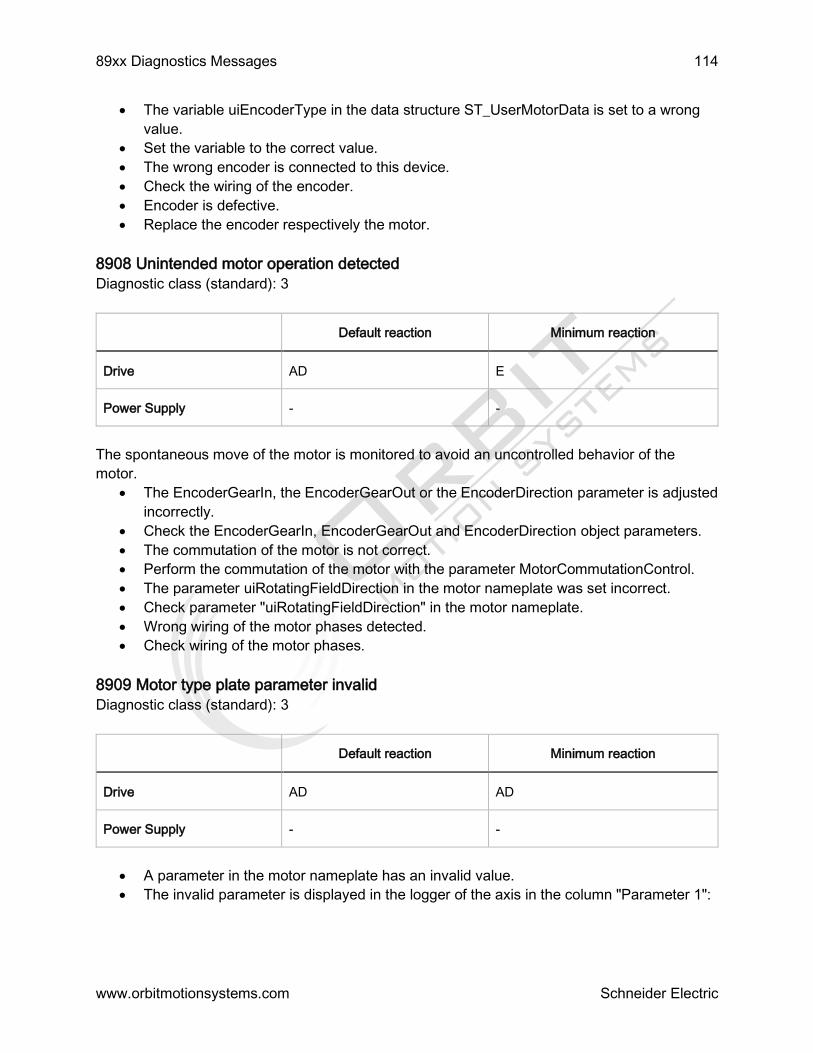
89xx Diagnostics Messages 114
www.orbitmotionsystems.com Schneider Electric
The variable uiEncoderType in the data structure ST_UserMotorData is set to a wrong
value.
Set the variable to the correct value.
The wrong encoder is connected to this device.
Check the wiring of the encoder.
Encoder is defective.
Replace the encoder respectively the motor.
8908 Unintended motor operation detected
Diagnostic class (standard): 3
Default reaction Minimum reaction
Drive AD E
Power Supply - -
The spontaneous move of the motor is monitored to avoid an uncontrolled behavior of the
motor.
The EncoderGearIn, the EncoderGearOut or the EncoderDirection parameter is adjusted
incorrectly.
Check the EncoderGearIn, EncoderGearOut and EncoderDirection object parameters.
The commutation of the motor is not correct.
Perform the commutation of the motor with the parameter MotorCommutationControl.
The parameter uiRotatingFieldDirection in the motor nameplate was set incorrect.
Check parameter "uiRotatingFieldDirection" in the motor nameplate.
Wrong wiring of the motor phases detected.
Check wiring of the motor phases.
8909 Motor type plate parameter invalid
Diagnostic class (standard): 3
Default reaction Minimum reaction
Drive AD AD
Power Supply - -
A parameter in the motor nameplate has an invalid value.
The invalid parameter is displayed in the logger of the axis in the column "Parameter 1":

89xx Diagnostics Messages 115
www.orbitmotionsystems.com Schneider Electric
Parameter 1 Description
1 rMainInductance is invalid or
rMotorCosPhi is invalid (if rNominalPower < 0.7 kW)
2 rStatorResistance is invalid or
rMotorCosPhi is invalid (if rNominalPower < 0.7 kW)
3 eMotorType is invalid
4 uiNominalPower or rNominalPower is invalid
5 uiEncoderType
8910 Reference value invalid
Diagnostic class (standard): 3
Default reaction Minimum reaction
Drive BD1 E
Power Supply - -
A position reference value was transferred via the SERCOS real-time channel which cannot be
reached within a SERCOS cycle.
The function FC_SetRefPosFromPos() was called up for an axis that is under control
and follows the reference values (AxisState >=3). Thereby the resulting jump in the
reference position must be large enough so that a reference velocity is calculated, which
is twice as big as the parameter MaxVel.
Use FC_SetRefPosFromPos() in the AxisState < 3.
Set FC_SetRefPosFromPos() to a position that leads to a smaller jump, regarding the
current reference position.
A wrong reference position was calculated in the controller.
Contact your responsible contact partner.
8911 Name too long
Diagnostic class (standard): 3
The name of a controller configuration object exceeded the maximum permissible length of 40
characters. This can be detected in the Name parameter of the object. The entered value of the
Name parameter is shortened to 38 characters and increases to 40 characters through the
added ".." .
The name of the controller configuration object exceeds 40 characters.

89xx Diagnostics Messages 116
www.orbitmotionsystems.com Schneider Electric
Shorten object name to a maximum of 40 characters.
8957 SERCOS bus topology changed
Diagnostic class (standard): 2
Reaction: D
For every change in topology (ring interruption or ring repair), the diagnosis message (warning)
with the following DiagExtMsg is issued:
DiagExtMsg Description
Top=1 line port 1 (ring was interrupted such that a device line is present at port 1)
Top=2 line port 2 (ring was interrupted such that a device line is present at port 2)
Top=3 double line (ring was interrupted such that one device line is present at port 1 and one
device line is present at port 2)
Top=4 ring (ring interruption has been rectified. Ring has been repaired.)
Top=8 Invalid topology (switchover not possible)
8958 Encoder communication not possible
Diagnostic class (standard): 3
Default reaction Minimum reaction
Drive BD2 CD
Power Supply - -
When reading the encoder an error occurred.
Wiring error: Encoder cable is not correct.
Check the wiring.
The control voltage of the device (24V DC) is too low.
Check control voltage.
Hardware error: Encoder is defective.
Change out the motor or the encoder.
8959 Mains contactor error detected
Diagnostic class (standard): 3

89xx Diagnostics Messages 117
www.orbitmotionsystems.com Schneider Electric
Default reaction Minimum reaction
Drive - -
Power Supply BP1 BP1
The DC bus is charged before the ready contact is closed by the device.
The mains contactor is not affected by the ready contact of the device.
Switch mains contactor via the ready contact of the device.
8960 Invalid mains voltage mode setting
Diagnostic class (standard): 2
Default reaction Minimum reaction
Drive - -
Power Supply D E
The value of the parameter MainsVoltageMode is not set in accordance to the in-feed voltage.
This warning is given out if at the end of the pre-charge phase the DC bus voltage is higher than
560V (by MainsVoltageMode=230V) or lower than 460V (by MainsVoltageMode=400V).
Possible causes are:
The setting of the parameter MainsVoltageMode is wrong.
Check the parameters.
Interruption of one or more phases of the mains feed-in.
Check the wiring of the mains phases.
8961 Phase missing message
Diagnostic class (standard): 2
Default reaction Minimum reaction
Drive - -
Power Supply D E
A phase of the mains connection of the device is not operational.
Check the wiring of the mains connection.
8963 NRT IPAddr not in IPAddressRangeStatic

89xx Diagnostics Messages 118
www.orbitmotionsystems.com Schneider Electric
Diagnosis class (Default): 2
The manually allocated IP address is not within IPAddressRangeStatic.
Check whether a Slave with IPConfigMode unequal Automatic IP addressing / 0 is
configured.
Check whether there is an IP address that is not within the calculated
IPAddressRangeStatic.
If IPConfigMode = Manual IP addressing (hardware) / 1, check the IP address that was
set on the hardware (for example with a switch) or via the Drives Assistant.
If IPConfigMode = Manual IP addressing (software) / 2, check the IP address that was
set in the parameter.
8964 NRT IPAddressRangeDynamic used up
Diagnosis class (Default): 2
The automatic IP address allocation system cannot allocate any more IP addresses from
IPAddressRangeDynamic.
Check whether the calculated address range IPAddressRangeDynamic is big enough to
provide all slaves with IP addresses using IPConfigMode = Automatic IP addressing / 0.
8965 NRT IP parameter read not possible
Diagnosis class (Default): 2
The SERCOS III parameter reading process cannot be executed.
The parameters IPAddress, Subnet mask and Gateway are read from the slaves via
SERCOS III if IPConfigMode = Manual IP addressing (hardware) / 1 is set.
Check whether the device supports the parameters.
8966 NRT IP parameter write not possible
Diagnosis class (Default): 2
The SERCOS III parameter writing process cannot be executed.
The parameters IPAddress, Subnetmask and Gateway are transferred to the slaves via
SERCOS III.
(By IPConfigMode = Automatic IP addressing / 0 or manual IP addressing (software) /
2).
Check whether the device supports the parameters
8967 NRT IP parameter device different
Diagnosis class (Default): 2
The logical sub-devices (e.g. the two drive objects of the double drive) have different
parameter values for IP addressing.
The message logger entry is triggered by one of the two logical devices in the PLC
configuration.
In the field Ext.Diagnosis, the name of the second device of the double drive is specified.
Check whether the two drive objects in the PLC Configuration contain the same values
for IPConfigMode.
89xx Diagnostics Messages 119
www.orbitmotionsystems.com Schneider Electric
If IPConfigMode of the two drive objects equals Manual IP addressing (software) / 2, the
parameters IPAddress, Subnetmask and Gateway must match as well.
NOTE: The faulty configuration of a double drive slave may be the reason why the slave is not
being configured.
8968 NRT network overlapping detected
Diagnosis class (Default): 2
The host ranges of the network at the standard Ethernet port of the controller and the SERCOS
III NRT channel overlap.
This overlap is caused by changing the NetID or the setting on the standard Ethernet port.
Changing the NetID
Before allocating any IP addresses, it is checked whether the networks and the currently
set NetID overlap. If this is the case, a message logger entry is triggered.
At the same time, the system tries to fix the problem automatically by first accessing the
default value of the parameter NetID (172.20.0.0). If the overlap continues to exist, the
NetID 172.21.0.0 is used instead.
If the problem could be solved this way, the message "corrected" is entered in the field
Ext.Diagnosis of the message logger.
If the overlap could not be removed, then the NetID set by the user is used to allocate
the IP address parameters. In the field Ext.Diagnosis of the message logger the „ip
com.deact.“ is entered and the IP communication between the controller and the NRT
channel is deactivated.
If the IP address settings are set valid again then the IP communication is active again.
Thereby no message logger entry is triggered.
Check the current set NetID or the communication setting on the standard Ethernet port
(see below) and adjust them if necessary, so that no network overlap can occur
anymore.
Changing the standard Ethernet port
If the communication settings on the standard Ethernet port of the controller are changed
and no network overlap with the existing SERCOS III settings is detected, then the IP
communication to the NRT channel is deactivated. The message 8968 appears with the
Ext.Diagnosis „ip com.deact.“ in the message logger.
If these communication settings are set valid again, then the IP communication is active
again. Thereby no message logger entry is triggered.
Check the current set NetID (see above) or the communication settings on the standard
Ethernet port and adjust them if necessary, so that no network overlap can occur
anymore.
NOTE: The check-ups for the network overlapping are performed at different times. This is why
it can happen that the message is displayed in the message logger several times.
8969 Motor cable not connected
Diagnostic class (Default): 3

89xx Diagnostics Messages 120
www.orbitmotionsystems.com Schneider Electric
Default reaction Minimum reaction
Drive AD AD
Power Supply - -
This diagnostic message is triggered if Curr_I_Gain and Curr_P_Gain are not set correctly, or if
ControllerEnable is set to TRUE and the measured current deviates more than 30% from the
expected value.
If ControllerEnable is set to TRUE, then a check is performed to see if a motor is connected to
the device. If no motor was detected, then this diagnostic message is triggered. The test can be
deactivated with the Motor ConnectionTest paramter.
The motor cable was not connected correctly.
Check wiring.
8970 Fast Device Replacement
Diagnosis class (Default): 1
The "Ext. diagnosis start" shows the start of the Fast Device Replacement. With the "Ext
diagnosis end" the end of a Fast Device Replacement is displayed. Between start and end the
activities of the Fast Device Replacement are recorded. An entry with the version number in the
ext. diagnosis signals that the firmware was exchanged successfully on the concerned device.
If there are no entries between start and end, then the Fast Device Replacement detected in the
status check/1 that an exchange of the firmware on the devices does not have to be performed.
8971 Fast Device Replacement not successful
Diagnosis class (Default): 2
The diagnosis message shows that the firmware of a device could not be exchanged. In the ext.
diagnosis the error is described more precisely.
Restrictions
The Fast Device Replacement can be performed on the devices Lexium62 Double Drive, Single
Drive and Power Supply. If Fast Device Replacement shall be performed, then it is reasonable
to carry out the addressing of the devices via the topological address or else an exact allocation
of the devices cannot be guaranteed after the exchange. For this, the value TopologyAddress/2
has to be allocated to the parameter IdentificationMode of the devices.
8972 NRT gateway not in network
Diagnosis class (Default): 2
The manual entered gateway (IPConfigMode = Manual IP addressing (hardware) / 1 or
Manual IP addressing (software) / 2) is not within the network that was defined with
NetID.
Check the manual entered gateway and adjust it properly so that it is within the network
that was defined with NetID, if necessary.

89xx Diagnostics Messages 121
www.orbitmotionsystems.com Schneider Electric
8973 Program download
Diagnosis class (Default): 1
When downloading a project the diagnosis "Program download" is triggered.
8974 Brake voltage too low
Diagnosis class (Default): 3
The error is set if the control voltage of the device (24V direct voltage) is not sufficient enough to
release the brake. It can be set before or after the release of the brake.
The brake voltage is monitored permanently. If the value of the brake voltage is lower than
specified in the technical data sheet of the device, then the error is set.
Check if the control voltage of the device (24 V direct voltage) is within the specified
limit values (see technical data sheet of the device) when the brake is released.
8975 Motor commutation invalid
Diagnosis class (Default): 2
Default reaction Minimum reaction
Drive D E
Power Supply - -
There is no commutation saved in the motor nameplate. The diagnosis message is only
triggered if the user tries to bring the motor in control mode.
The motor commutation has to be determined with the automatic commutation determination.
This functionality can be controlled with the parameter MotorCommutationControl.
8976 Mains phases wiring not correct
Diagnostic class (Default): 3
Default reaction Minimum reaction
Drive - -
Power Supply BP1 BP1
The mains phases were not connected to the device correctly.
The wiring of the mains phases is not correct (for example, only one individual phase
was connected to the device in the three-phase operating mode).
Check the wiring of the mains phases.
8977 Motor temp. monitoring disabled
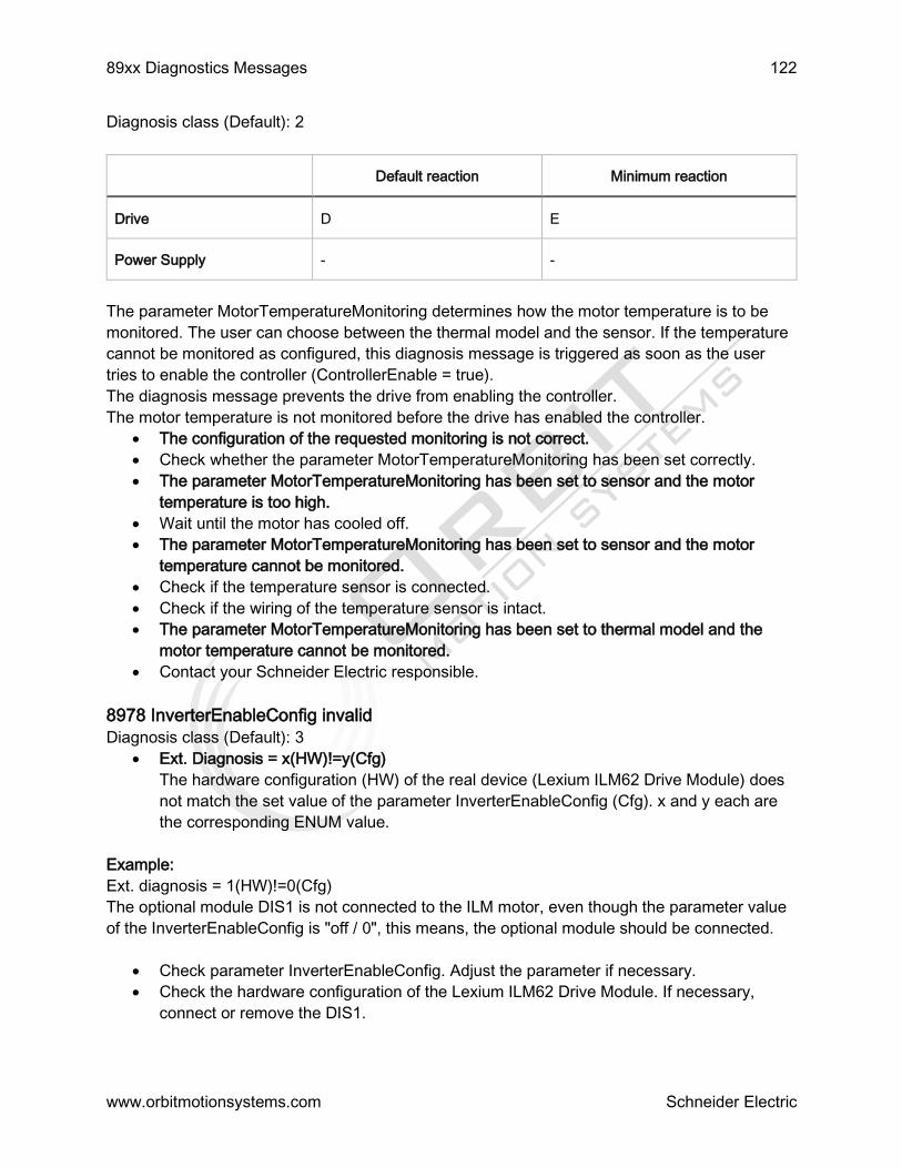
89xx Diagnostics Messages 122
www.orbitmotionsystems.com Schneider Electric
Diagnosis class (Default): 2
Default reaction Minimum reaction
Drive D E
Power Supply - -
The parameter MotorTemperatureMonitoring determines how the motor temperature is to be
monitored. The user can choose between the thermal model and the sensor. If the temperature
cannot be monitored as configured, this diagnosis message is triggered as soon as the user
tries to enable the controller (ControllerEnable = true).
The diagnosis message prevents the drive from enabling the controller.
The motor temperature is not monitored before the drive has enabled the controller.
The configuration of the requested monitoring is not correct.
Check whether the parameter MotorTemperatureMonitoring has been set correctly.
The parameter MotorTemperatureMonitoring has been set to sensor and the motor
temperature is too high.
Wait until the motor has cooled off.
The parameter MotorTemperatureMonitoring has been set to sensor and the motor
temperature cannot be monitored.
Check if the temperature sensor is connected.
Check if the wiring of the temperature sensor is intact.
The parameter MotorTemperatureMonitoring has been set to thermal model and the
motor temperature cannot be monitored.
Contact your Schneider Electric responsible.
8978 InverterEnableConfig invalid
Diagnosis class (Default): 3
Ext. Diagnosis = x(HW)!=y(Cfg)
The hardware configuration (HW) of the real device (Lexium ILM62 Drive Module) does
not match the set value of the parameter InverterEnableConfig (Cfg). x and y each are
the corresponding ENUM value.
Example:
Ext. diagnosis = 1(HW)!=0(Cfg)
The optional module DIS1 is not connected to the ILM motor, even though the parameter value
of the InverterEnableConfig is "off / 0", this means, the optional module should be connected.
Check parameter InverterEnableConfig. Adjust the parameter if necessary.
Check the hardware configuration of the Lexium ILM62 Drive Module. If necessary,
connect or remove the DIS1.

89xx Diagnostics Messages 123
www.orbitmotionsystems.com Schneider Electric
8979 STO_A and STO_B different levels
Diagnosis class (Default): 3
Default reaction Minimum reaction
Drive AD AD
Power Supply - -
This diagnosis message is triggered if the inputs STO_A and STO_B have different levels. Both
inputs always have to have identical levels.
The wiring of the inputs is faulty.
Check the wiring of the inputs.
8980 Braking resistor not connected
Diagnosis class (Default): 3
Default reaction Minimum reaction
Drive BD2 BD2
Power Supply - -
This diagnosis message is triggered if an external braking resistor is configured but not
connected.
The external braking resistor is not connected to the device.
Connect braking resistor.
The internal braking resistor shall be used but the parameter
ExternalBrakingResistorEnableSet is set to "on / 1".
Set parameter ExternalBrakingResistorEnableSet to "off / 0".
The external braking resistor is defective.
Exchange braking resistor.
8981 Bootloader update
Diagnostic class (Default): 1
The bootloader of the device was updated.
8982 Device state
Diagnostic class (Default): 1
The current condition of the device (InternalDeviceState parameter) has changed.
8983 DC bus precharge active

89xx Diagnostics Messages 124
www.orbitmotionsystems.com Schneider Electric
Diagnostic class (Default): 1
Loading the DC bus.
8984 DC bus precharge complete
Diagnostic class (Default): 1
The precharge of the DC bus is completed.
8990 Firmware update not possible
Diagnostic class (Default): 1
The firmware of the device could not be updated.
SERCOS is in phase 4. A firmware update is only possible in phase 0.
Switch SERCOS to phase 0.
The selected firmware is not compatible with the device (for example, the LXM52
firmware shall be installed in a LXM62 drive).
Check if the selected firmware is compatible with the device.
8991 Data transfer invalid
Diagnostic class (Default): 1
During the download of the new firmware a transmission error was detected.
Data transfer error.
Repeat the firmware download.
Check cable.
8992 Braking resistor short circuit
Diagnosis class (Default): 3
Default reaction Minimum reaction
Drive AD AD
Power Supply - -
This diagnosis message is triggered if a short circuit was detected on the input for the external
braking resistor.
The external braking resistor is short-circuited.
Check the wiring of the external braking resistor.
The external braking resistor is defective.
Exchange braking resistor.
8993 Last device on SERCOS port
Diagnosis class (Default): 1
Ext. diagnosis:
"Px TAddr y"

89xx Diagnostics Messages 125
www.orbitmotionsystems.com Schneider Electric
with x = Port number and y = TopologicalAddress
Structure: NodeId = xxx
After a topology change in doublet this message is triggered in addition to the diagnosis
message 8957 SERCOS bus topology changed.
8994 Invalid ProducerCycleTime
Diagnosis class (Default): 3
Ext. diagnosis:
"xxxxxxx ns"
with xxxxxxx = Value of the parameter ProducerCycleTime with x = Port number
and y = TopologicalAddress
This message is triggered by the SERCOS run-up if the parameter ProducerCycleTime of a
SERCOS IO device is not an integer multiple of the SERCOS cycle time.
8995 Update motor type plate
Diagnosis class (Default): 1
This diagnosis message is triggered as a general message if the automatic update of the
electronic motor type plates was started.
Additional, this diagnosis message is triggered as a specific message for every motor on which
the automatic update has been completed successfully.
8996 Update motor type plate not successful
Diagnosis class (Default): 3
This diagnosis message is triggered as a general message if the automatic update of the
electronic motor type plates was not completed successfully altogether.
Additional, this diagnosis message is triggered as a specific message for every motor on which
the automatic update has not been completed successfully.
In the specific diagnosis message the following error codes are specified:
Fehlercode Meaning
-1 Error in the updated type plate.
-2 Error when reading the previous type plate.
-3 Unexpected data field length.
-4 Reinitialization of the drive failed.
-5 IDN read-/writing error P(101,0,0) / (P(1034,0,0).
-10 *.blh file not found.

89xx Diagnostics Messages 126
www.orbitmotionsystems.com Schneider Electric
-11 *.blh format error (no 8 data byte).
-12 *.blh format error (no byte).
The update of the electronic motor type plates was not successful.
Contact your Schneider Electric responsible.
8997 MotorIdentification invalid
Diagnostic class (Default): 3
The parameter MotorIdentification has an invalid value.
The parameter is set to Motor with nameplate / 0, but the electronic motor nameplate is
saved in the servo amplifier.
Check if the axis assignment in the PLC configuration is correct.
Set parameter to Motor without nameplate / 1.
The parameter is set to Motor without nameplate / 1 but the electronic motor nameplate
is saved in the encoder EEPROM of the motor.
Check if the axis assignment in the PLC configuration is correct.
Set parameter to Motor with nameplate / 0.
8998 TM5/TM7 Supply voltage too low
Diagnostic class (Default): 3
Reaction: manufacturer-specific
This diagnostic message is triggered if the PowerSupplyMonitoring parameter is set to Enabled
/ 1 and one or several of the TM5 power supply units (TM5SPS1, TM5SPS1F, TM5SPS2 ,
TM5SPS2F) connected to a TM5 bus interface (TM5NS31) or a TM7 output module lost the 24
V supply voltage.
8999 TM5/TM7 Warning supply voltage
Diagnostic class (Default): 1
Reaction: manufacturer-specific
This diagnostic message is triggered if the PowerSupplyMonitoring parameter is set to Message
/ 2 and one or several of the TM5 power supply units (TM5SPS1, TM5SPS1F, TM5SPS2 ,
TM5SPS2F2) connected to a TM5 bus interface (TM5NS31) or a TM7 output module lost the 24
V supply voltage.

Diagnostic Messages of the Runtime System 127
Schneider Electric
In addition to the listed messages in the chapter Diagnostic messages the message logger can
display diagnostic messages of the runtime system in EPAS and Diagnostics.
These messages have a diagnostic code that deviates from the normal format:
A decimal greater than 1073741824 is displayed as diagnostic code.
Composition of the diagnostic code
If the decimal diagnostic code of the message is converted into a hexadecimal, then the digit 4 displays in
the first place that it is a runtime system message.
Examples
The following explains some possible runtime system messages:
Task cycle time monitoring
Column
message logger
Value Description
Class 4 Diagnostic class 4
Object LZS Runtime system
Instance LZS Runtime system
DiagCode 1073746179 Diagnostic code (HEX:
0x40001103)
Ext. Diag 16 External diagnostic: Indicates the
time the task required (in ms).
Message *EXCEPTION* Watchdog Application <Task
name that caused the cycle time overrun>
Exception occurred by the task
cycle time monitoring:
Example: *Exception* Watchdog
Application TASK_S
Application is not loaded
Column message
logger
Value Description
Class 3 Diagnostic class 3

Diagnostic Messages of the Runtime System 128
www.orbitmotionsystems.com Schneider Electric
Object LZS Runtime system
Instance LZS Runtime system
DiagCode 1073742337 Diagnostic code (HEX: 0x40000201)
Ext. Diag 1 External diagnostic
Diagnostic text Application <Application name> not
found to start
The application could not be loaded.
Example: Application Prepare not
found to start
Boot project is not loaded
Column message
logger Value Description
Class 3 Diagnostic class 3
Object LZS Runtime system
Instance LZS Runtime system
DiagCode 1073742350 Diagnostic code (HEX:
0x4000020E)
Ext. Diag 16 External diagnostic
Diagnostic text Boot project <Boot project name>
corrupt
The boot project could not be
loaded.
Exception FC_SysUserCallStack
Column message
logger Value Description
Class 4 Diagnostic class 4

Diagnostic Messages of the Runtime System 129
www.orbitmotionsystems.com Schneider Electric
Object LZS Runtime system
Instance LZS Runtime system
DiagCode 1073746179 Diagnostic code (HEX: 0x40001103)
Ext. Diag 8192 External diagnostic: Number given by the
user
Diagnostic text *EXCEPTION* <Exception type>
Application
Exception occurred by the function
FC_SysUserCallStack.
Example: *EXCEPTION* VendorException
Application
Field bus is not running
Column message
logger Value Description
Class 3 Diagnostic class 3
Object LZS Runtime system
Instance LZS Runtime system
DiagCode 1079970304 Diagnostic code (HEX: 0x405F0A00)
Ext. Diag -2146697191 External diagnostic
Diagnostic text Could not get destination queue
handle
Diagnostic of the CAN driver: Field bus is
not running
Display in the PLC configuration
NOTE: The individual diagnostic values of the messages are also displayed in the diagnostic parameters
of the PLC configuration (for example, PacDrive LMC x00C > Configuration > Section Diagnostic):

Diagnostic Messages of the Runtime System 130
www.orbitmotionsystems.com Schneider Electric
Value Parameters of the PLC Configuration
Class DiagClass
DiagCode DiagCode
Diagnostic text DiagMsg
Ext. Diag DiagExtMsg
3 Shannon Court Unit 305
Bristol RI 02809
401-213-3320
2016