pacemaker troubleshooting- single chamber pacemakers
TRANSCRIPT

Pacemaker troubleshooting-single chamber pacemakers
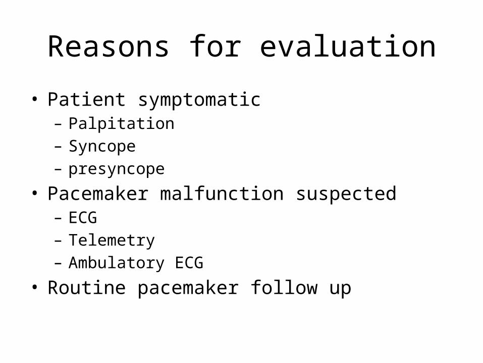
Reasons for evaluation
• Patient symptomatic– Palpitation– Syncope – presyncope
• Pacemaker malfunction suspected– ECG– Telemetry– Ambulatory ECG
• Routine pacemaker follow up
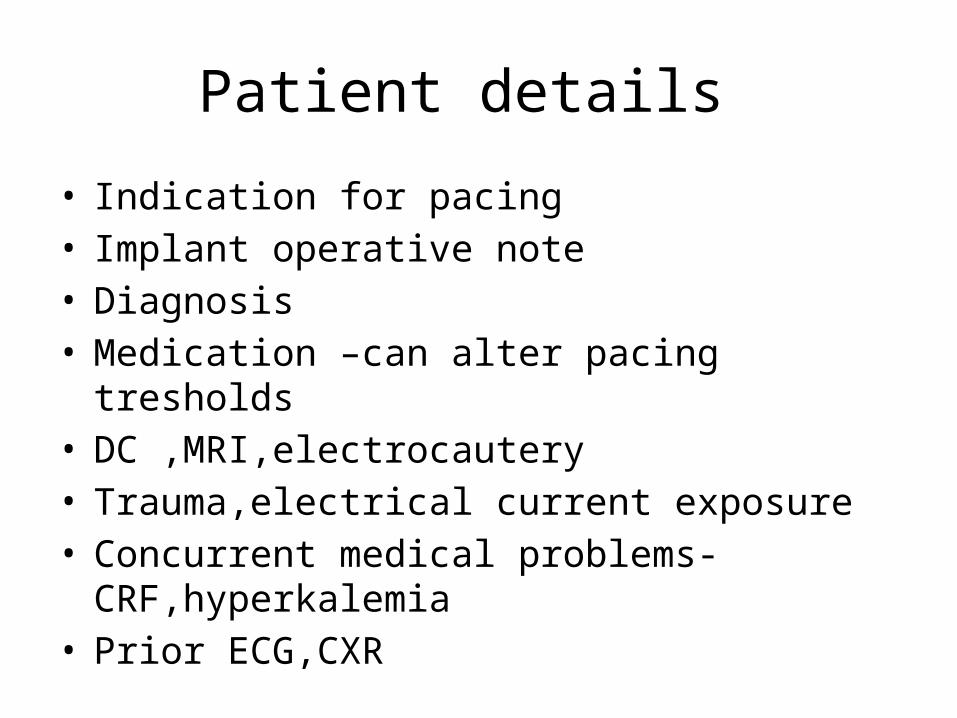
Patient details
• Indication for pacing• Implant operative note• Diagnosis• Medication –can alter pacing tresholds• DC ,MRI,electrocautery• Trauma,electrical current exposure• Concurrent medical problems-CRF,hyperkalemia• Prior ECG,CXR
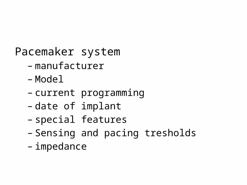
Pacemaker system– manufacturer– Model– current programming– date of implant– special features– Sensing and pacing tresholds– impedance
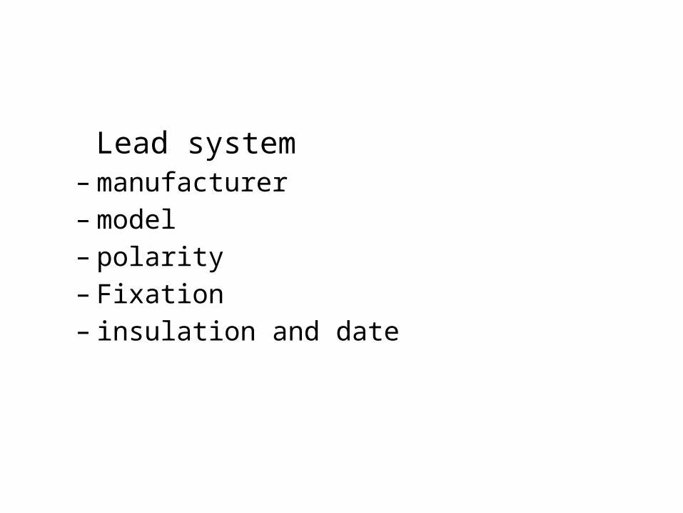
Lead system– manufacturer– model– polarity– Fixation– insulation and date
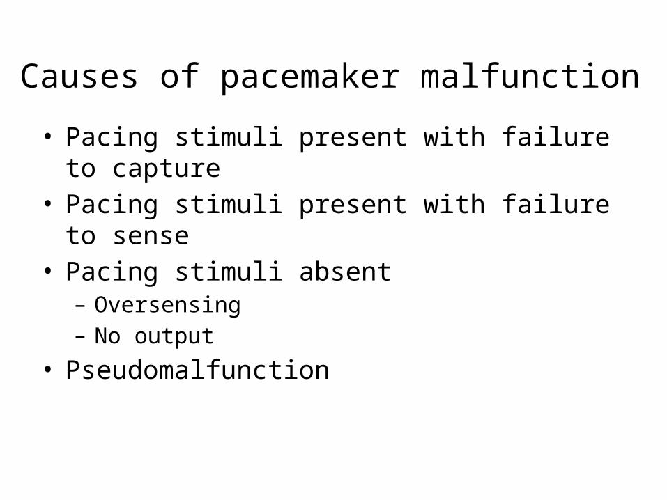
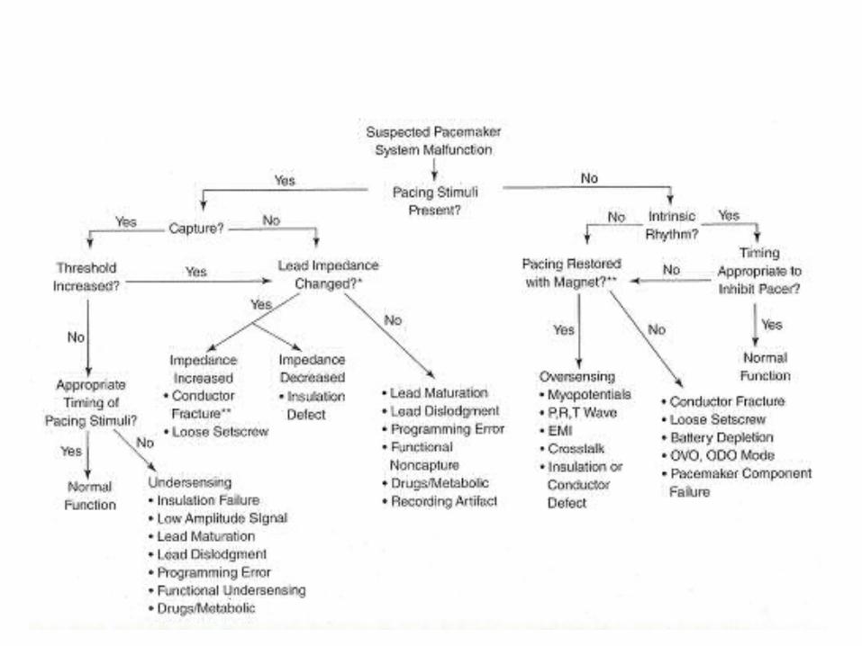
Causes of pacemaker malfunction
• Pacing stimuli present with failure to capture• Pacing stimuli present with failure to sense• Pacing stimuli absent– Oversensing– No output
• Pseudomalfunction
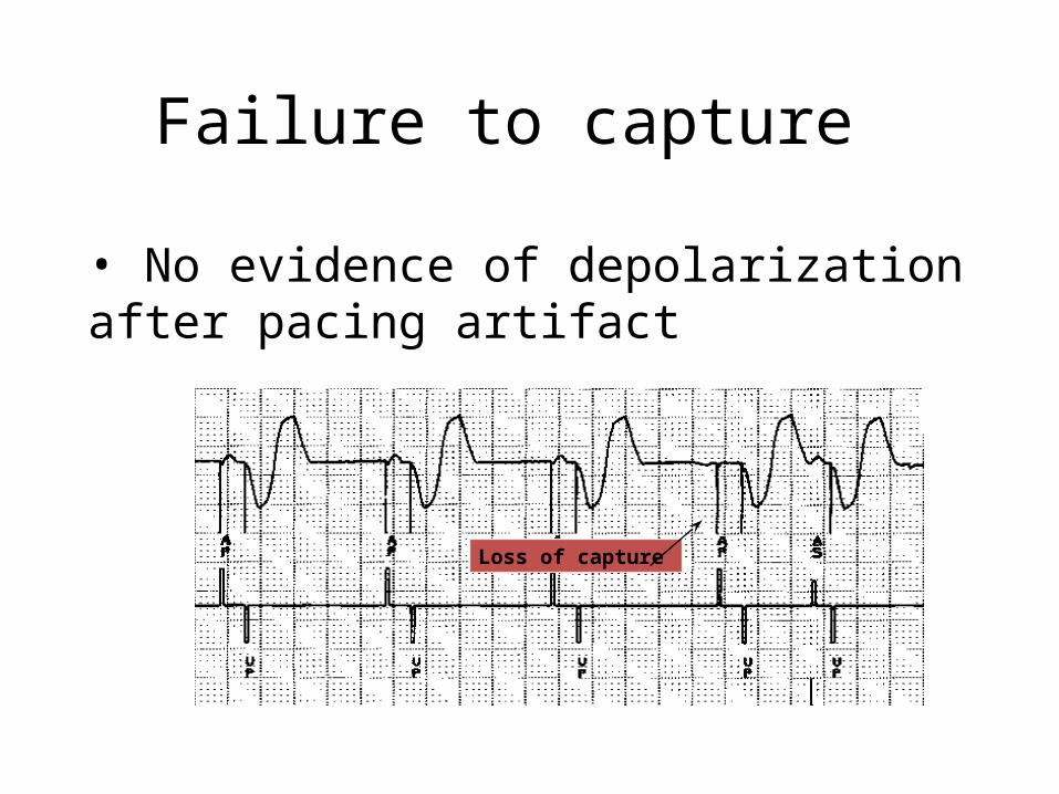
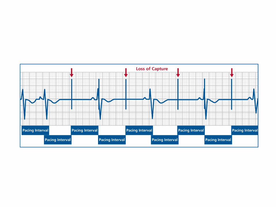
Failure to capture
• No evidence of depolarization after pacing artifact
Loss of capture
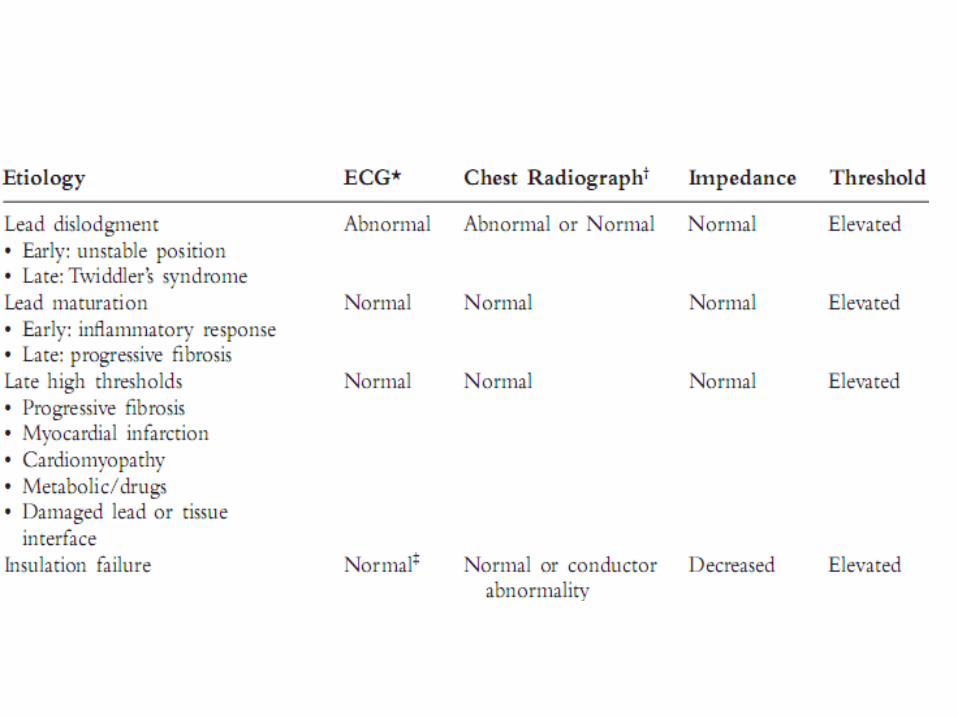
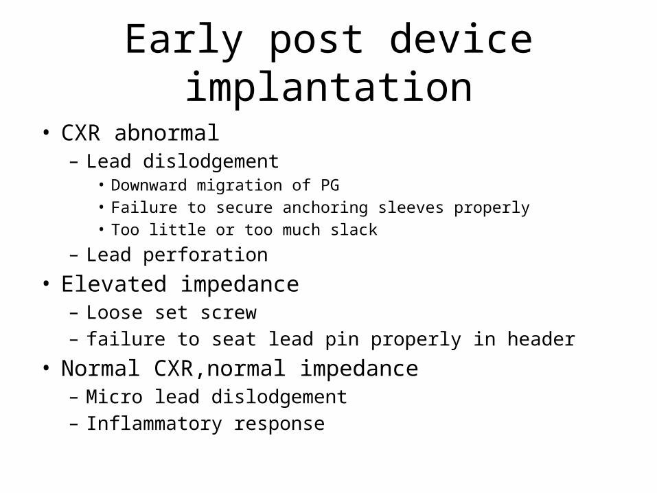
Early post device implantation
• CXR abnormal– Lead dislodgement
• Downward migration of PG• Failure to secure anchoring sleeves properly• Too little or too much slack
– Lead perforation
• Elevated impedance– Loose set screw– failure to seat lead pin properly in header
• Normal CXR,normal impedance– Micro lead dislodgement– Inflammatory response
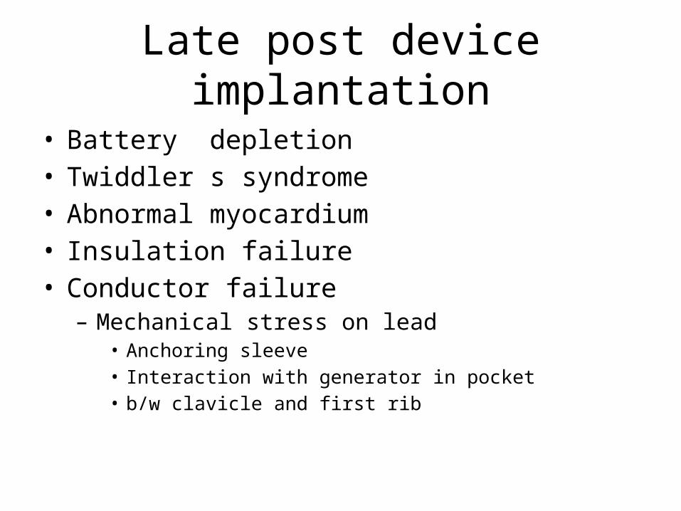
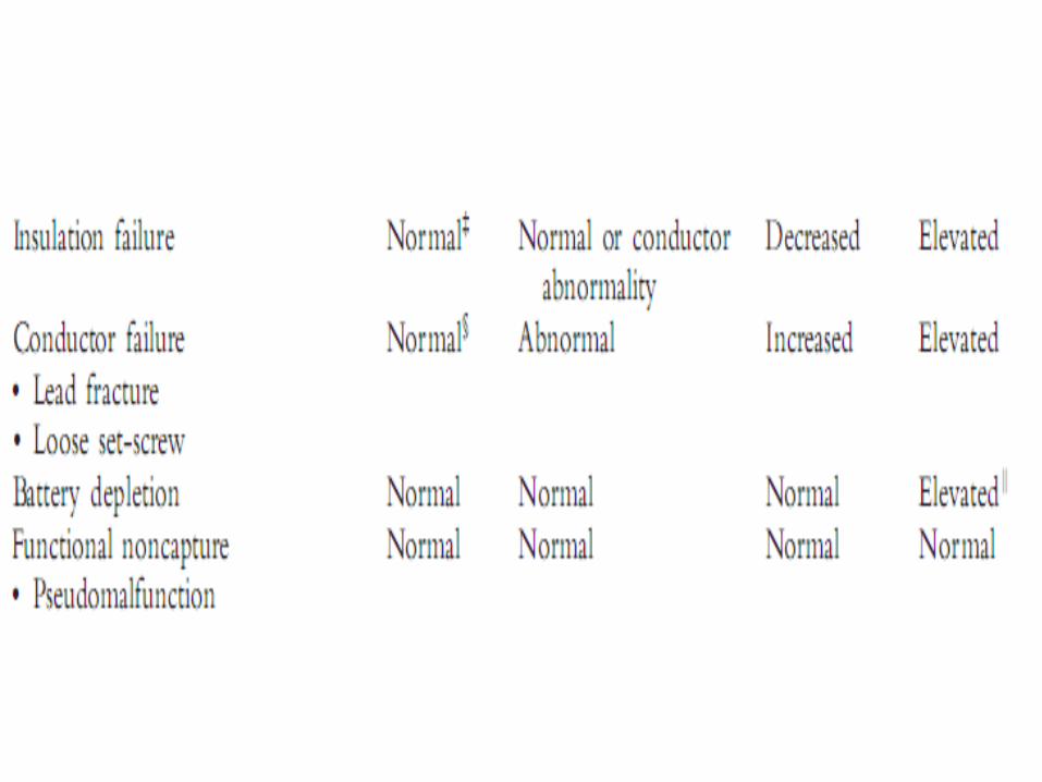
Late post device implantation
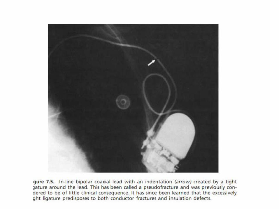
• Battery depletion• Twiddler s syndrome• Abnormal myocardium• Insulation failure• Conductor failure– Mechanical stress on lead
• Anchoring sleeve• Interaction with generator in pocket• b/w clavicle and first rib

• Increase the energy in the output pulse– Run a capture threshold test– Adjust the output parameters, if necessary• Pulse amplitude (V)• Pulse width or duration (ms)
– It is generally more efficient to increase the pulse amplitude
• Investigate possible lead problems• Reprogram device polarity
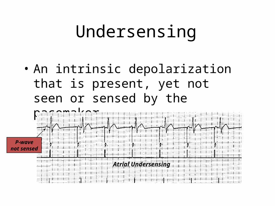
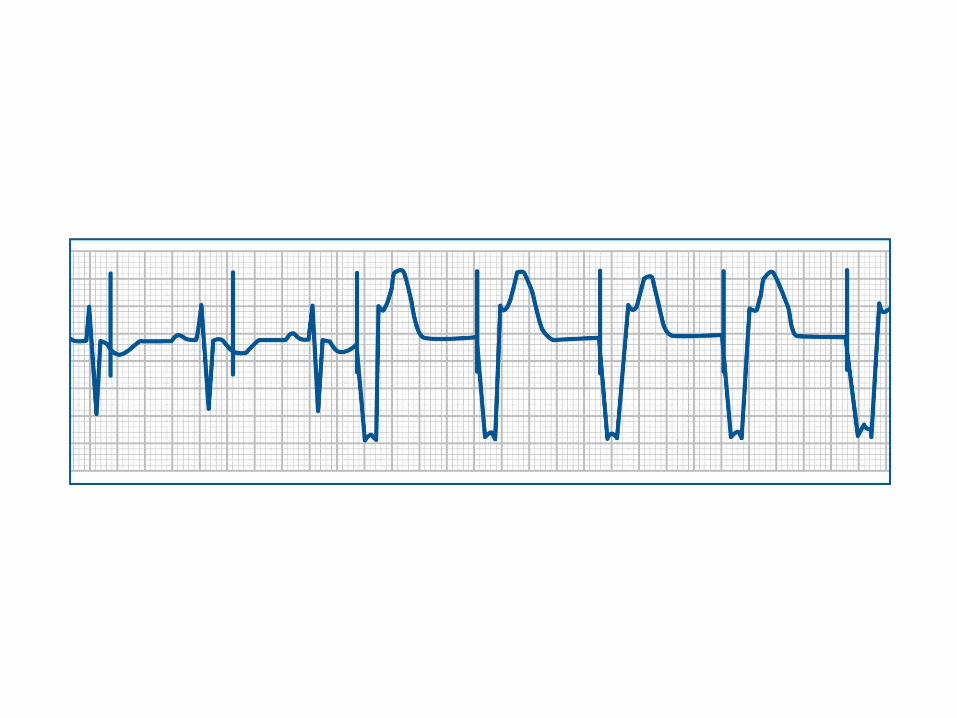
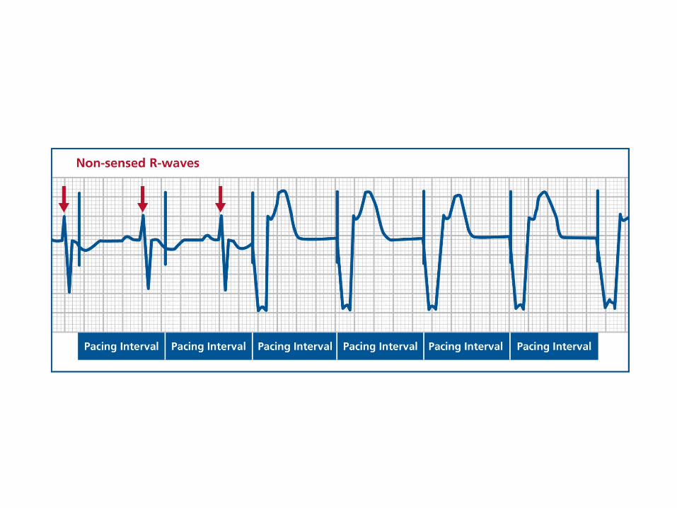
Undersensing
• An intrinsic depolarization that is present, yet not seen or sensed by the pacemaker
P-wavenot sensed
Atrial Undersensing

• Undersensing occurs when the pacemaker does not detect intrinsic activity that really is there
• Undersensing causes the pacemaker to pace more than it should
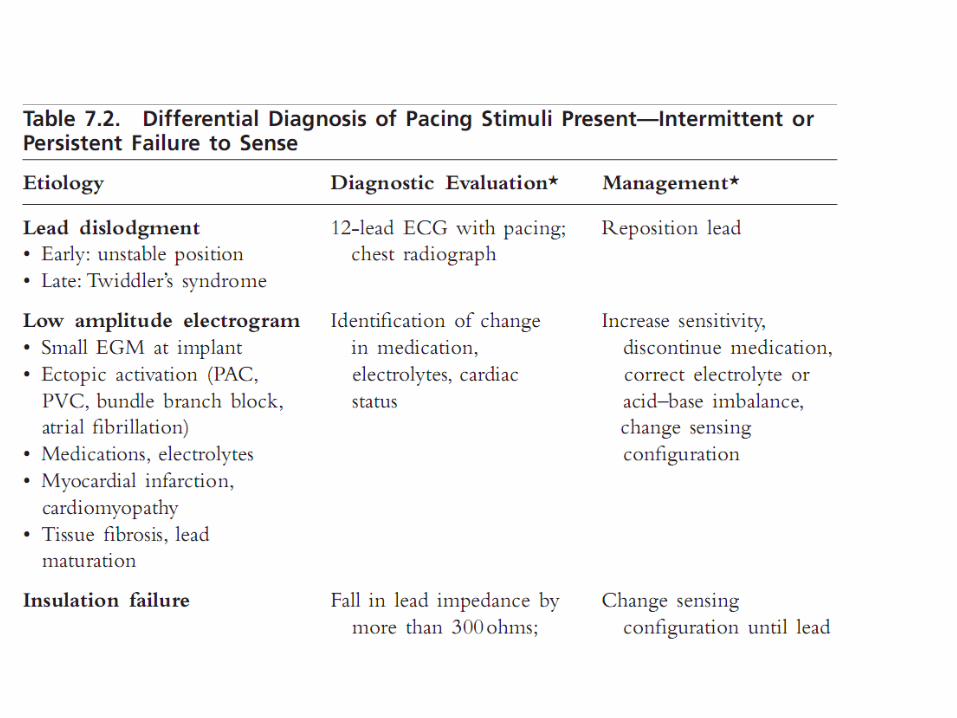
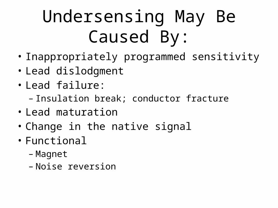
Undersensing May Be Caused By:
• Inappropriately programmed sensitivity• Lead dislodgment• Lead failure:– Insulation break; conductor fracture
• Lead maturation• Change in the native signal • Functional – Magnet– Noise reversion
• Adjust the sensitivity setting– Run a sensing threshold test– Measure the intrinsic signals– Adjust the sensitivity appropriately• To increase sensitivity, decrease the mV setting
– Make all changes to sensitivity settings in small steps since large changes may only introduce new sensing problems
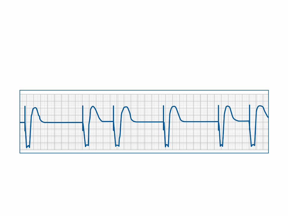
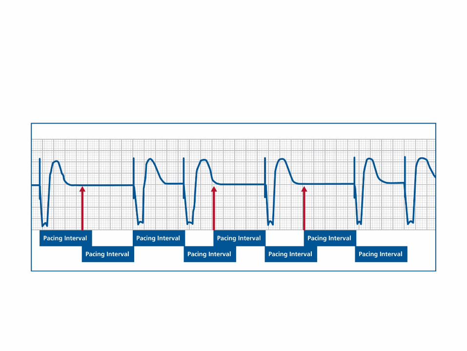
Oversensing
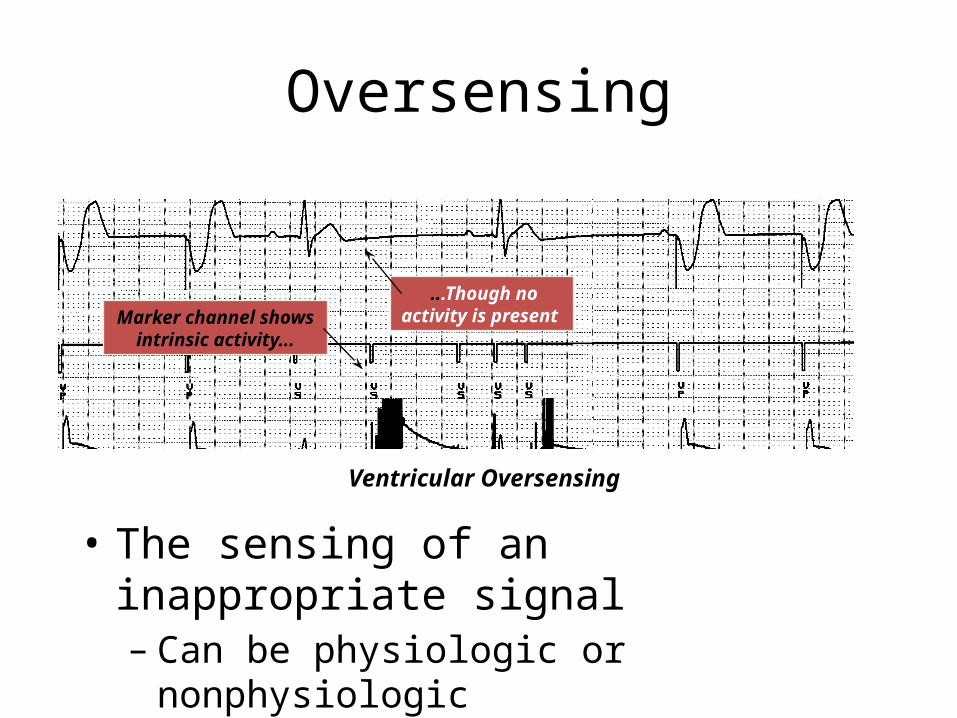
Ventricular Oversensing
Marker channel shows intrinsic activity...
...Though no activity is present
• The sensing of an inappropriate signal – Can be physiologic or nonphysiologic
• Oversensing occurs when the pacemaker inappropriately “thinks” that it sees intrinsic activity that is not there
• Oversensing causes the pacemaker to inhibit the pacing output pulse, even though the device should be pacing
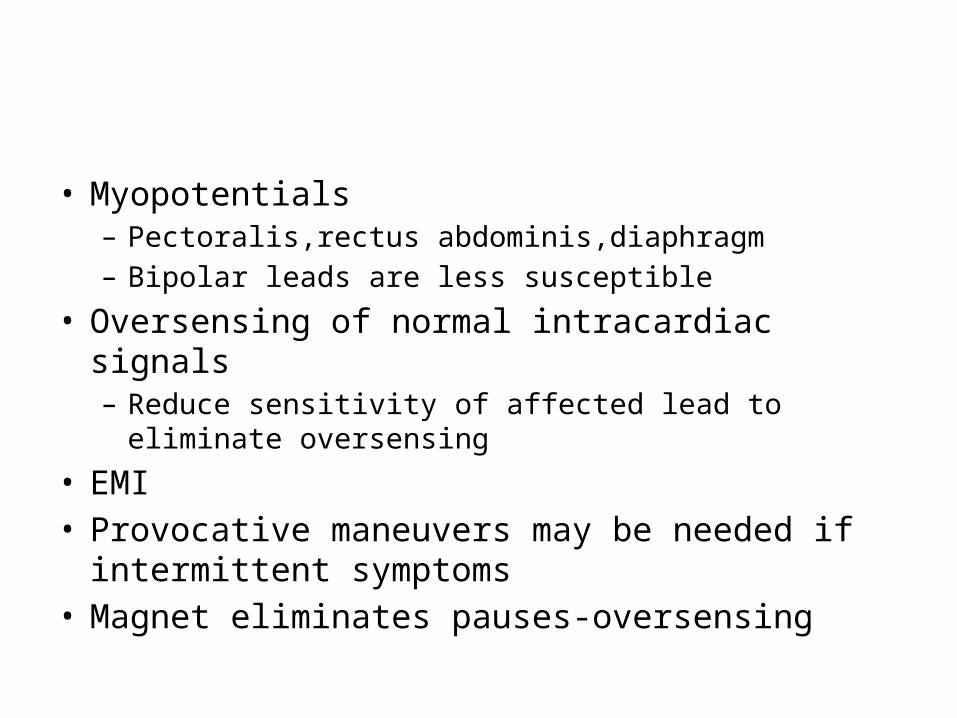
• Myopotentials– Pectoralis,rectus abdominis,diaphragm– Bipolar leads are less susceptible
• Oversensing of normal intracardiac signals– Reduce sensitivity of affected lead to eliminate
oversensing
• EMI• Provocative maneuvers may be needed if
intermittent symptoms• Magnet eliminates pauses-oversensing
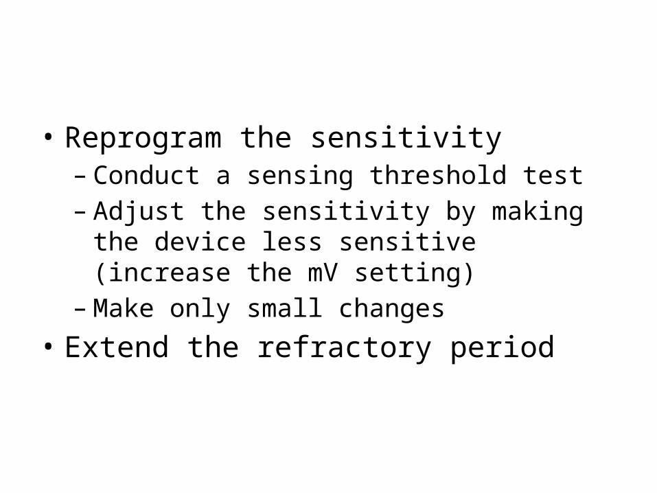
• Reprogram the sensitivity– Conduct a sensing threshold test– Adjust the sensitivity by making the device less
sensitive (increase the mV setting)– Make only small changes
• Extend the refractory period
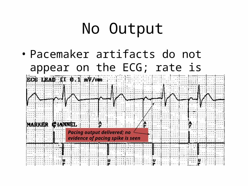
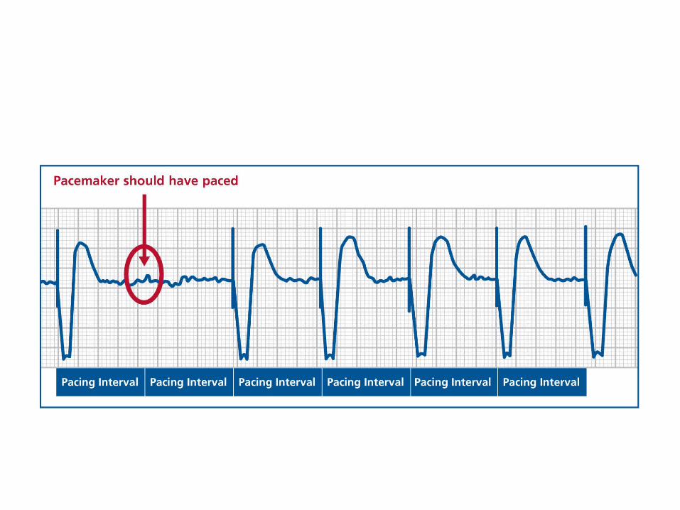
No Output
• Pacemaker artifacts do not appear on the ECG; rate is less than the lower rate
Pacing output delivered; no evidence of pacing spike is seen
No Output May Be Caused By:
• Poor connection at connector block• Lead failure• Battery depletion• Circuit failure
• Steps to take for possible loss of output– Verify all lead connections– Check lead integrity– Evaluate battery status– Contact the device manufacturer
• Loss of output may require the replacement of all or part of the pacing system
Pseudomalfunctions
Pseudomalfunctions are defined as: Unusual,Unexpected ECG findings that appear
to result from pacemaker malfunction but that represent normal pacemaker function

• Hysteresis• Magnet rate• rate responsive pacing• Noise reversion• Rate drop response• Sleep rate algorithm
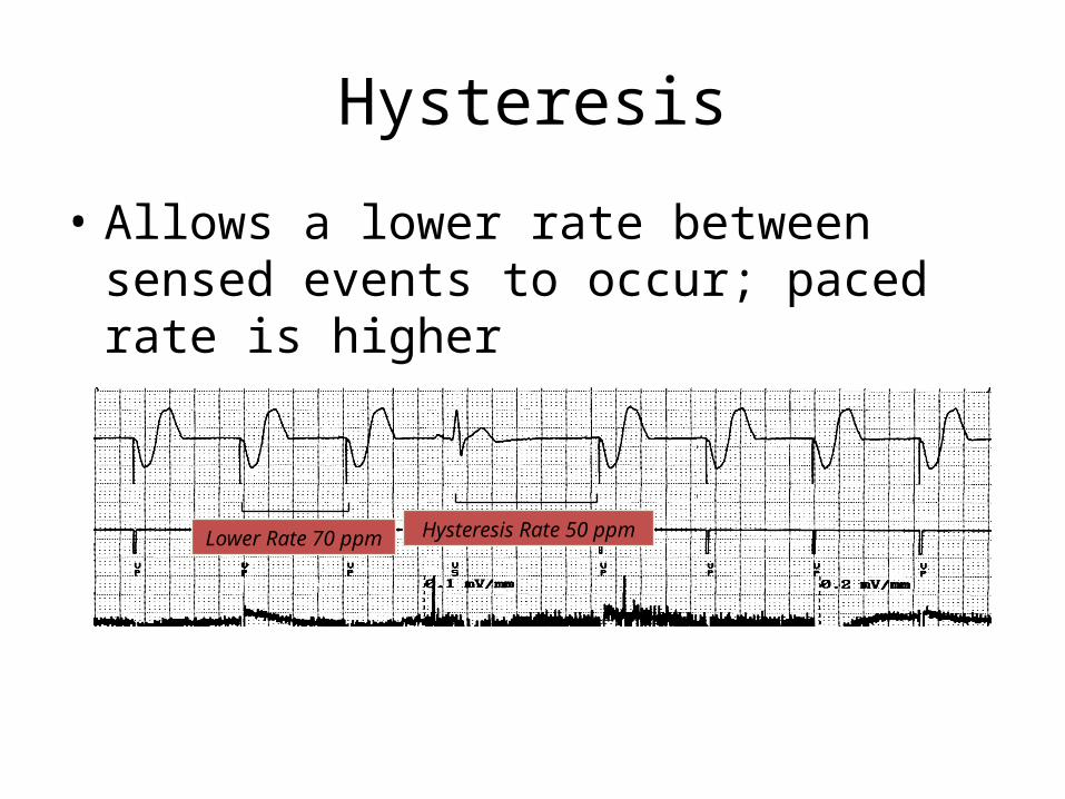
Hysteresis
• Allows a lower rate between sensed events to occur; paced rate is higher
Lower Rate 70 ppm Hysteresis Rate 50 ppm

Magnet Operation
• Magnet application causes asynchronous pacing at a designated “magnet” rate
• Threshold Margin Test (TMT)• Three beats at 100 bpm, followed by a magnet rate of 85• Third beat has an automatic pulse width decrement of 25% • Elective replacement indicators-change the rate from 85 to
65
• Extended TMT.– TMT is performed at 100 ppm– Pulse width reduced by 25% on 3rd , 50% on 5th , and 75%
on 7th

Rate Responsive Pacing
• An accelerating or decelerating rate may be perceived as anomalous pacemaker behavior
VVIR / 60 / 120

Electrical Reset and Battery Depletion• Reset may occur due to exposure to EMI electrocautery, defibrillation, causing reversion to a “back-
up” mode– Rate and mode changes will occur– Device can usually be reprogrammed to
former parameters• Elective replacement indicators (ERI) can resemble back-up
mode– Interrogating device will indicate ERI
(“Replace Pacer”)
A Change in Pacing Modes May Be Caused By:
• Battery depletion indicators (ERI/EOL)• Electrical reset• Mode switching• Noise reversion
Noise Reversion
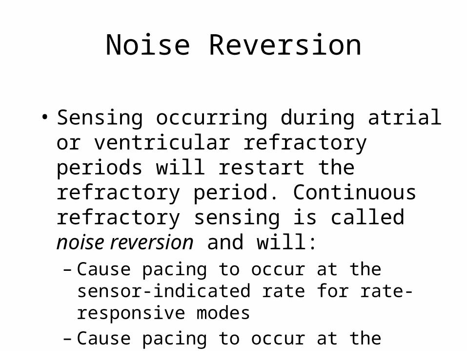
• Sensing occurring during atrial or ventricular refractory periods will restart the refractory period. Continuous refractory sensing is called noise reversion and will:– Cause pacing to occur at the sensor-indicated rate
for rate-responsive modes– Cause pacing to occur at the lower rate for non-
rate-responsive modes
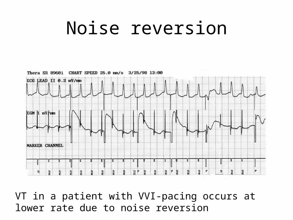
Noise reversion
VT in a patient with VVI-pacing occurs at lower rate due to noise reversion

Rate drop response
Delivers pacing at high rate when episodic drop in rate occurs
Muscle Stimulation May Be Caused By:
• Inappropriate electrode placement near diaphragm or nerve plexus
• Break in lead insulation • Unipolar pacing
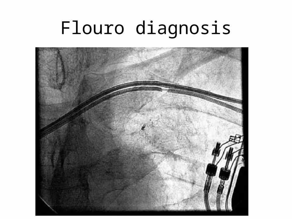
Flouro diagnosis

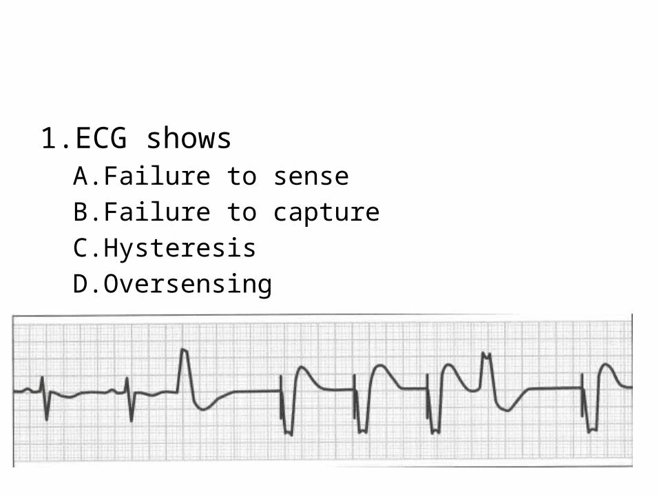
1.ECG showsA.Failure to senseB.Failure to captureC.HysteresisD.Oversensing
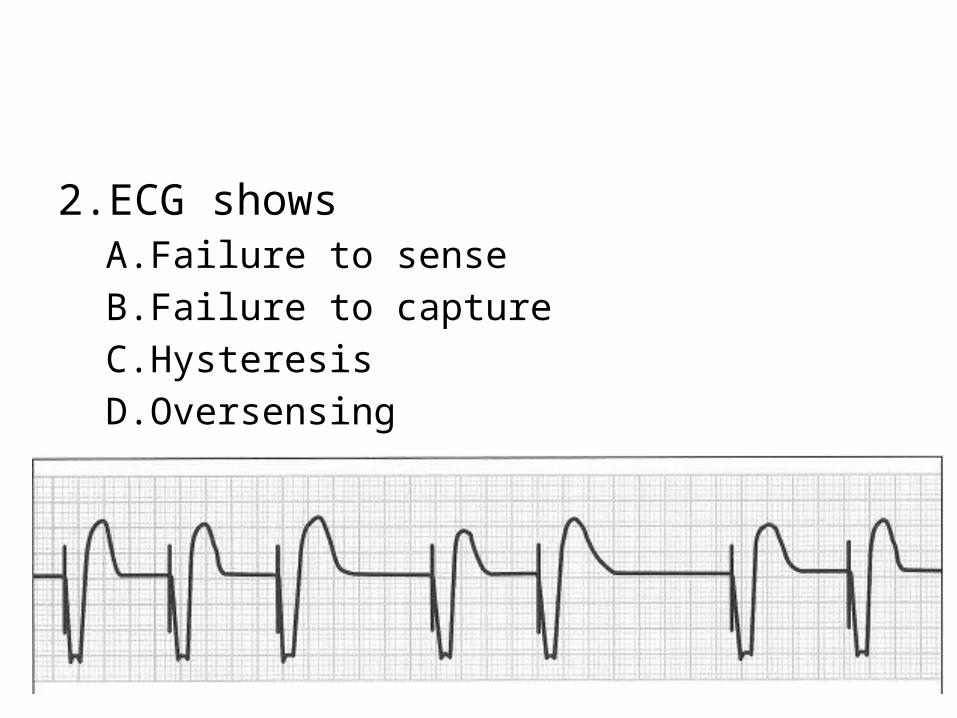
2.ECG showsA.Failure to senseB.Failure to captureC.HysteresisD.Oversensing
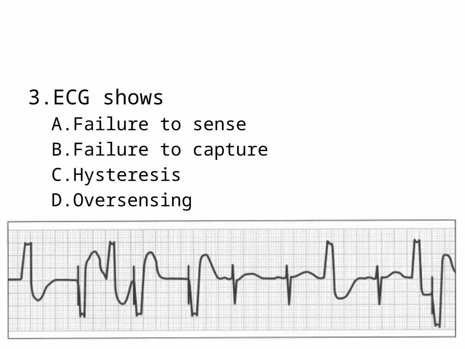
3.ECG showsA.Failure to senseB.Failure to captureC.HysteresisD.Oversensing
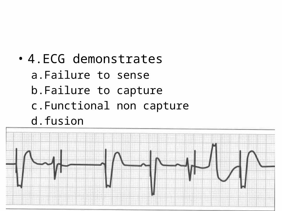
• 4.ECG demonstratesa.Failure to senseb.Failure to capturec.Functional non captured.fusion
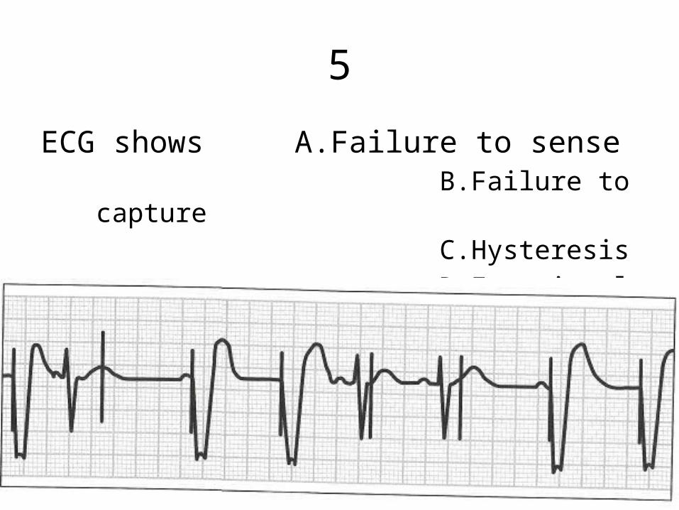
5
ECG shows A.Failure to sense B.Failure to capture C.Hysteresis D.Functional non capture
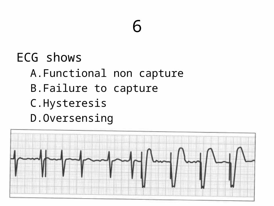
6
ECG showsA.Functional non captureB.Failure to captureC.HysteresisD.Oversensing
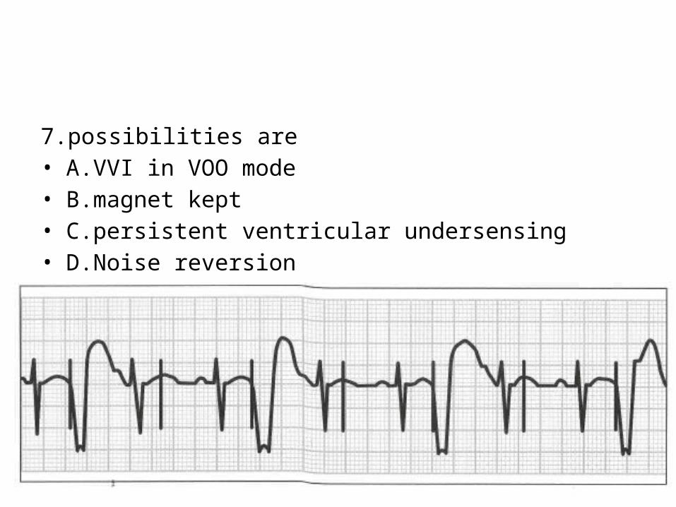
7.possibilities are• A.VVI in VOO mode• B.magnet kept• C.persistent ventricular undersensing• D.Noise reversion

• 8.make and break potentials usually cause• A.undersensing• B.oversensing• C.functional non capture• D.failure to capture

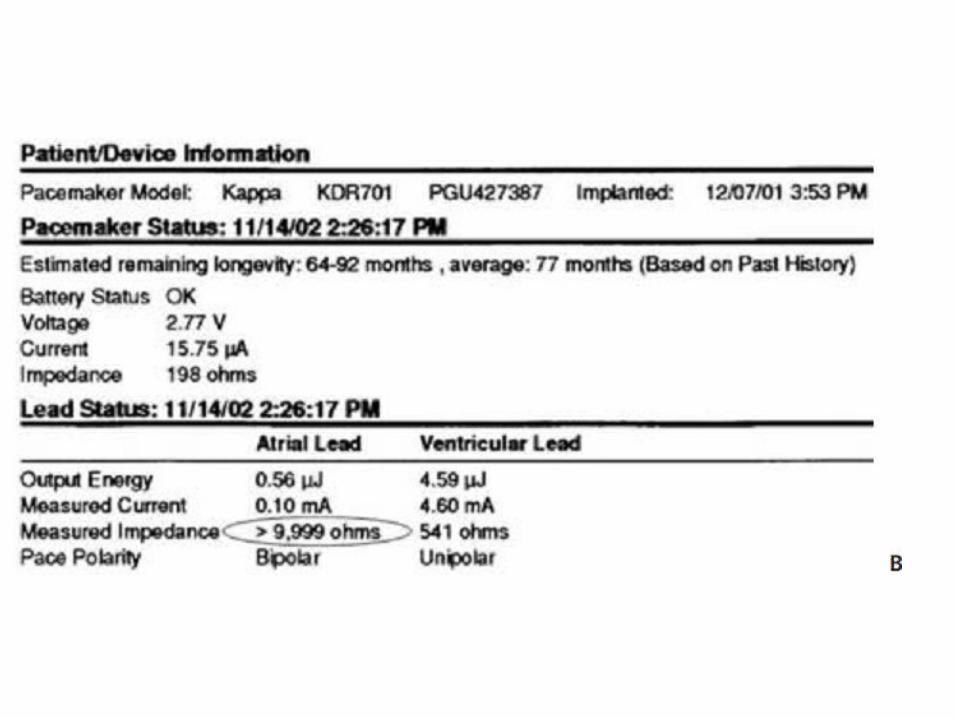
• 9.elevated pacing threshold and elevated impedance can be caused by
• A.lead fracture• B.loose set screw• C.insulation failure• D.battery depletion
• 10.elevated threshold with decreased impedance caused by
• A.lead fracture• B.loose set screw• C.insulation failure• D.battery depletion
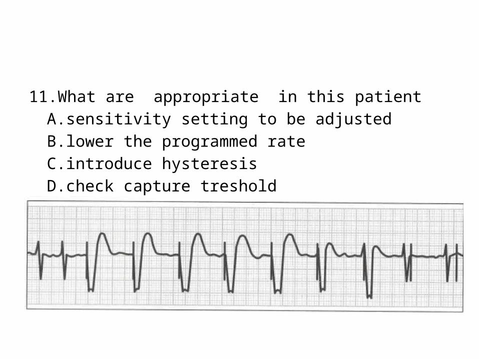
11.What are appropriate in this patientA.sensitivity setting to be adjustedB.lower the programmed rate C.introduce hysteresisD.check capture treshold
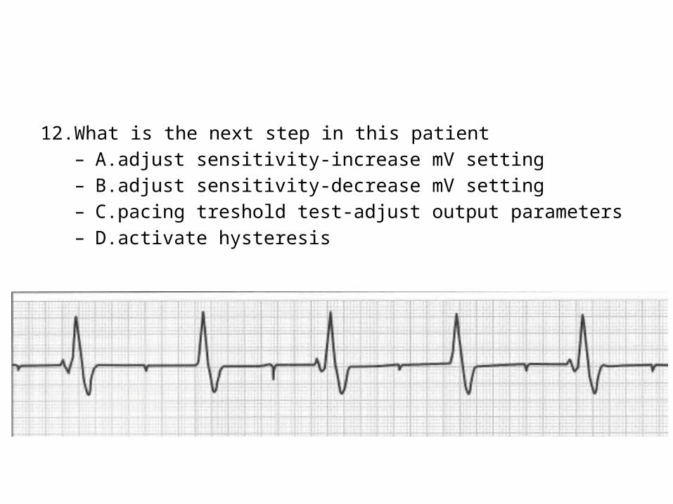
12.What is the next step in this patient– A.adjust sensitivity-increase mV setting– B.adjust sensitivity-decrease mV setting– C.pacing treshold test-adjust output parameters– D.activate hysteresis
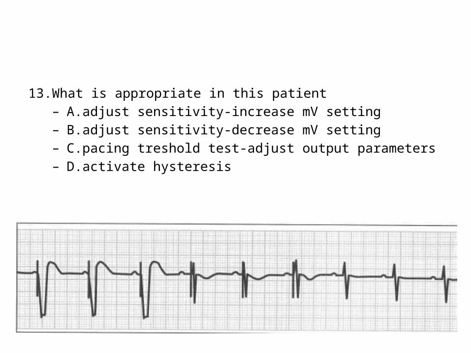
13.What is appropriate in this patient– A.adjust sensitivity-increase mV setting– B.adjust sensitivity-decrease mV setting– C.pacing treshold test-adjust output parameters– D.activate hysteresis

14.What is appropriate in this patient– A.adjust sensitivity-increase mV setting– B.adjust sensitivity-decrease mV setting– C.pacing treshold test-adjust output parameters– D.activate hysteresis

15.What is appropriate in this patient– A.adjust sensitivity-increase mV setting– B.adjust sensitivity-decrease mV setting– C.pacing treshold test-adjust output parameters– D.activate hysteresis