pad system international limited€¦ · · 2017-03-01no part of this publication and pad...
TRANSCRIPT

USER GUIDE
v5
PAD System International Limited
www.padsystem.com
Digitizer Manager Version 5

PAD System™ is a trademark and a system developed by: PAD System™ International Limited Unit B, D, 11/F, Gee Hing Chang Industrial Bldg, 16 Cheung Yue Street, Cheung Sha Wan, Kowloon, Hong Kong Telephone: (852) 2370-9178 Fax: (852) 2370-9085 E-mail: [email protected] Technical support: [email protected] Website: www.padsystem.com No part of this publication and PAD System™ software may be reproduced, transmitted, transcribed, stored in a retrieval system, or translated into any language in any part form by any means without the written permission of PAD System™ International Ltd. Any unauthorized duplication or use of PAD System™, in whole or in part, in print, or in any other storage and retrieval system is forbidden. © 1988-2010 PAD System™ International Limited All rights reserved. PAD System™ International Ltd © 2010
2

Chapter 1 The Digitizer Manager Basics . . . . . . . . .
Working Area Interface
The working area shows pieces and floating windows in the Digitizer Manager Program.
The Job List window shows on the working area, visible or not. The Info bar is located at the bottom of the window. The Info bar displays:
Default Unit Given Medium Size Quantity of sizes in grading nest Cursor position on the working area Job Status Number of users connecting
3

Zoom Menu
In the lower left-hand corner of the main application window, five buttons allow you to use different Zoom views.
The Zoom menu button allows you to control the zoom level. You can select a pre-set zoom percentage or enter a specific zoom percentage. By default, the zoom level is set to 15% on every new file opened.
To use this tool, simply click the appropriate pre-set zoom value. You
can enlarge size from 0.5% up to 2000%. The Global View item displays all the visible pattern pieces in the working area.
The Zoom on selection shows selected piece(s) in the center of the window.
The Global View button displays all the visible pattern pieces in the working area.
The Zoom Out and Zoom In buttons allow you to select preset view levels of 200%, 100%, 50%, 33%, 25%, 20%, 10%, 8%, 6%, 5%, 4% , 3%,
2%, 1% or 0.5%.
4

Types of Points
Points define both the contour and the inner indications of a pattern. PAD System™ uses three types of points:
Regular point: This type of point appears at the beginning and at the end of a segment.
The system reads a segment from one Regular point to the next Regular point,
including all points between the two ends. Regular points are added when working
on the pattern piece.
Mark point: Mark points are added to the contour of a pattern piece, by using either the
Add Point to Segment or Point tool.
Control point: These points pull on the segment to hold your curve. They are based on the Bezier curve principle.
Other point characteristics can identify Notches, Punch Holes, User’s Notches, User’s Punch Holes,
Matching Point, Start Point, Lift and Plunge, Symmetrical Start/End Point, Internal Start Point. You
can select these point characteristics using the Point characteristics dialog box or the Points and
Notches option in the Pattern program.
5

Segments A segment can be one of three things:
A polygon contour A style line, or A construction line between two points inside or outside a shape
A segment is considered as a construction line if it does not define any element of the pattern but is used as a guide for development. Many different functions can be applied to a segment. You can access information on Segment
Length and Segment Angle using the Plan View or Piece View Toolbox / Toolbar in the Pattern Program.
6

Selection and Activation To select an entire piece, click it using your mouse and the pointer tool.
No points are visible: The piece is not activated.
White points are visible: The piece is activated under the digitize process.
Black points are visible:
The piece is selected.
Click the mouse on any segment
to select the piece.
7

Keyboard Selection
To make a keyboard selection, press the left mouse button (Windows/Linux) / the mouse button (Macintosh) along with one of the following keys:
The Shift key (Windows, Macintosh and Linux) to select more than one element
The Esc key (Windows, Linux and Macintosh) to activate the Cancel button in any dialog box.
The Tab key to go from one field or button to another in a dialog box.
8

Hold down the Shift key and press the Tab key to move to the previous box.
Click a text box to activate it. Double-click it to select all the information it contains.
To scroll the view of the working area: Press and hold the Space bar (Windows, Macintosh and Linux).
A hand icon appears:
Hold down the left mouse button (Windows) / the mouse button (Macintosh) and move up,
down, left, right.
9

Job List
The Job List window shows the pieces on the working area. The minus sign and plus sign allow hiding or displaying the full list. To open a subjacent menu, click the +/- symbol. Press and hold the Alt (Windows) / Option (Macintosh) / Alt +Windows keys (Linux) and click the + or - sign to open or close the entire section (all the subjacent menus and elements) with a single click.
10

Use the two task buttons located at the top of Job List window to modify piece info in Job List.
Job List Buttons
Click this button to display the Piece Info dialog box. Alternatively, user can
double-click a piece to get the Piece Info dialog box.
Choose this button to Delete the selected piece(s). A dialog box asks whether you really want to delete your selection. Select Continue if yes, otherwise select Cancel to stop.
Customizing your Job List with Contextual Menu To obtain contextual menu, right click the mouse button on the Job List button bar. This enables you to customize the way you view the piece information.
Check on the item of the contextual menu to sort the pieces or change the way you view the information in the list.
11

Piece information: By Columns By checking the Info by Columns Option on the title bar, user views piece information arranged in vertical columns.
Right click the title bar to choose the
option by mouse left click
By un-checking the Info by Columns, user can view piece information in comma separated rows.
Right click the title bar to uncheck the
option by mouse left click
12
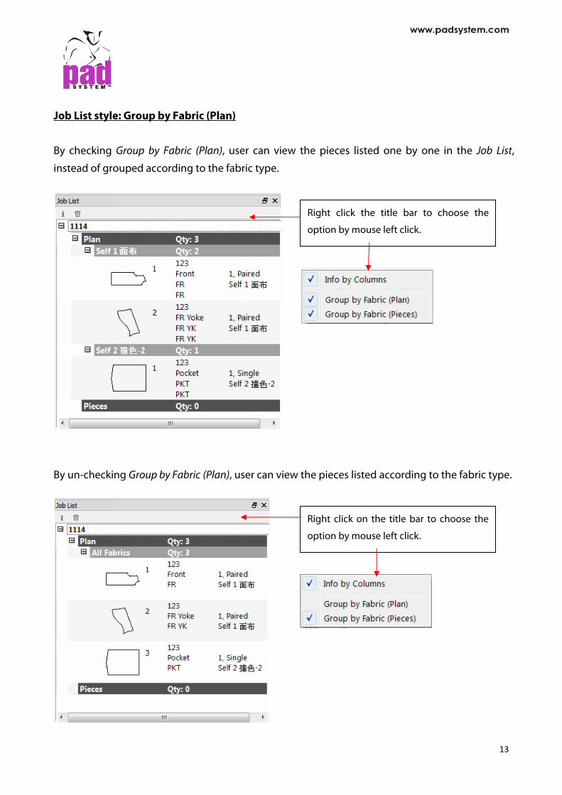
Job List style: Group by Fabric (Plan)
By checking Group by Fabric (Plan), user can view the pieces listed one by one in the Job List,
instead of grouped according to the fabric type.
Right click the title bar to choose the
option by mouse left click.
By un-checking Group by Fabric (Plan), user can view the pieces listed according to the fabric type.
Right click on the title bar to choose the
option by mouse left click.
13

Job List style: Group by Fabric (Pieces)
By selecting Group by Fabric (Pieces), you can view the pieces listed one by one in the Job List, instead of grouped according to fabric.
Right click the title bar to choose the
option by mouse left click.
By un-checking Group by Fabric (Pieces), you can view the pieces listed according to fabric type.
Right click the title bar to choose the
option by mouse left click.
You can select both Group by Fabric (Plan) and Group by Fabric (Pieces).
14

Piece Info
The Piece Info allows user to view or edit information on the selected piece(s).
User can access this dialog box via the Piece Information function on the Job List window by pressing the button or double click the selected piece by mouse.
To get the info of a piece: 1. Activate the piece to get info. 2. Click the Piece Information button in the Job List window. The Piece Info dialog box appears
as below.
15

The first section in the dialog box indicates the number of selected pieces.
The second section is the piece identification. It shows piece information appearing on the piece.
Pattern #: the style number.
Piece Name: the piece name, which can be selected from a predefined list in the Piece Name List… dialog box.
Description: additional information describing the piece.
Piece Code: indicates the need for special piece treatment or any additional information.
Reference Code: an identification code for the piece or any additional information that can be selected from a predefined list in the Option menu –> Reference Code List... by clicking the pop-up menu that has the shape of a triangle next to the text field.
Quantity to Be Cut: the quantity of pieces needed for a complete garment. Single means a right-side-up piece and Paired means two pieces: a left piece and a right piece.
Fabric: identifies a fabric for a given piece or group of pieces, which can be selected from a predefined list in the Options menu – Fabric List by clicking the pop-up menu that has the shape of a triangle next to the text field. If a color code is given, the piece changes/adds color automatically.
The third section allows user to identify or determine whether the piece is in Plan View or Pieces View.
Plan: indicates that a pattern piece is in Plan View.
Piece: indicates that a pattern piece is in Pieces View. Pieces in Pieces View appear in PAD System Marker modules.
The fourth section allows user to assign a color to the piece, providing better visual identification of the piece on the current working area or when making future modifications. If
the color of the fabric has been preset in the Options menu > Fabric List, the OK button will not be available.
16

Default Hot Keys Hot Keys enhance the speed and efficiency of your work.
Digitizer Manager offers some preconfigured Hot Key shortcuts that enable user to carry out
routine tasks using one, two, or three-key combinations.
The following Hot Key combinations are pre-set in your Digitizer Manager application:
Function Windows / Linux Macintosh
File: Quit Ctrl+Q Ctrl+Q
17
Chapter 2 Menu Bar . . . . . . . . File Menu
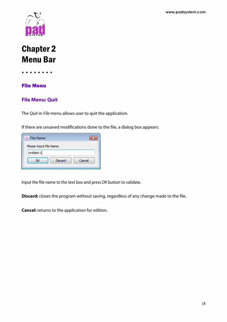
File Menu: Quit The Quit in File menu allows user to quit the application. If there are unsaved modifications done to the file, a dialog box appears:
Input the file name to the text box and press OK button to validate.
Discard: closes the program without saving, regardless of any change made to the file.
Cancel: returns to the application for edition.
18

Execute Menu
Execute Menu: Start / Stop
The Start /Stop item in the Execute menu is used to digitize pattern shapes using a digitizer. For the best possible viewing area, set the digitizing at a zoom level of 15%. User can see the current zoom level in the lower left area of the windows.
To digitize pattern pieces: 1. Select Start in the Execute menu. 2. Start digitizing when the cursor changes to Plus sign. When the digitizer is online, the info
bar displays "Now digitizing in Plan View".
If no digitizer was found, an error message shows up.
Verify your connection and settings in the Option -> Device Configurations… To stop pattern digitizing Once you start to digitize pattern pieces. The Start item will change to Stop. You can press Stop item to end the digitizing process. And then you can go to the Job List to change the Piece Information of the pattern pieces.
19

Selecting a Digitizer: 4- or 16- Button Puck or Digipen When using a PAD System digitizer, user can connect to the digit table a puck with either four or sixteen buttons, or the Digipen.
The 4-button puck and the Digi-Pen are used to input basic information on the pattern pieces: straight lines, curved lines, internal reference notches, punch holes and grain lines.
The 16-button puck is used to input basic information on the pattern pieces as well as other necessary information, such as: grain lines, grading evolutions (according to a grading library or a preset grading nest), internal references (punch holes, pocket lines) or a complete construction plan with style lines.
To select the proper setting for the digitizing puck, go to the Options menu, select Device Configurations….
This opens the Digitizer dialog box. You are asked to choose between the 4- or 16- button digitizer or the Algotex Digi-Pen 4. You can select from a list of commercial digitizers compatible with PAD System.
All digitizing methods begin the same way: 1. The digit table must be turned on and connected to working station.
2. Select the digitizer in the Option > Device Configurations… > Digitizer dialog box, which can be the 4-button, 4-button with extended capabilities, 16-button or the Algotex Digi-Pen 4, follow the appropriate steps as described in the next sections.
3. To digitize pattern pieces in a new file, select Start from the Execute menu. A blank page appears and let you to digitize pieces to.
20

Digitizing with the 4-Button Puck (PAD System 4) The 4-button puck is used to enter contour points and internal regular points on the pattern
piece. To select 4-button digitization, go to the Options menu, select Device Configurations….Select
PAD System 4 from the list of digitization options.
The four buttons on the puck allow you to enter different types of contour points and internal
punch holes. 4-Button Puck button functions:
Button Contour
1 Enter a regular contour point.
2 Enter a contour curve point. (Several #2 points can be made on a curve; the system calculates the exact curve.)
4* Internal reference regular points.
8** Enter other pattern pieces without returning to the screen.
Note: * On some digitizers, Button #4 may appear as Button #3.
** On some digitizers, Button #8 may appear as Button #4.
- On the GTCO Calcomp digitizer, Button #1 is the Yellow button, Button #2 is the White button,
Button #3 is the Green button and Button #4 is the Blue button. The Digitizer closes a polygon (pattern piece) when it reaches the first point digitized.
21

Digitizing a piece with the 4 Button:
To exit the Digitizer, select Stop in the Execute menu which allows user to end the digitizing process. Or click anywhere on the working area.
22

Digitizing using the 4-Button Puck with Extended Capabilities
To select 4-button digitization with extended capabilities, go to the Options menu, select Device Configurations…. Select PAD System 4 from the list of digitization options and check the Extended Capabilities (4 Buttons) box.
4-button digitization with extended capabilities allows you to digitize contour points (such as curve points, regular points and default PAD System notches) plus internal references (such as style lines, pocket lines and punch holes). Using extended capabilities to digitize contour points and external references. The four buttons on the puck allow you to enter different types of contour points and external references (see the next page for a similar chart on digitizing internal references).
4-Button Puck with Extended Capabilities Button Functions for the Perimeter of the Piece:
Button Perimeter
1 Enter a regular contour point.
2 Enter a contour curve point (several #2 points can be made on a curve; the system calculates the exact curve).
4* + 1 Enter a single notch. Click on 4 * on the perimeter, click on 1 for the length and orientation of the notch.
4* + 2 Enter a double notch. Click on 4 * on the perimeter, click on 2 for the length and orientation of the notch.
4* + 4 Enter a V notch. Click on 4 * on the perimeter, click on on 4* for the length and orientation of the notch.
8* Finish the contour. You are ready to enter the piece internal references.
8* + 8* Finish with the piece and enter another pattern piece if you do not need any internal references for this piece.
23

Using extended capabilities to digitize internal references The four buttons on the puck with extended capabilities allow you to enter different types of internal references once you have done with the perimeter (for example, punch holes and internal segments).
4-Button Puck with Extended Capabilities Button Functions for Internal References:
Button Internal References
1 Enter a regular internal point or beginning of a segment regular point.
2 Enter an internal curve point (Several #2 points can be made on a curve; the system calculates the exact curve).
4* + 1 Enter an internal punch hole.
4* + 2 Enter an internal point ending a segment.
4* + 4* Enter an internal punch hole ending a segment.
8** To indicate that you are finished entering internal references and are ready to start another piece.
Note: * On some digitizers, Button #4 may appear as Button #3.
** On some digitizers, Button #8 may appear as Button #4.
- On the GTCO Calcomp digitizer, Button #1 is the Yellow button, Button #2 is the White button,
Button #3 is the Green button and Button #4 is the Blue button.
24

Digitizing the perimeter of a piece with the 4-Button with extended capabilities:
25

Digitizing internal references of a piece with the 4-Button with extended capabilities:
26

Digitizing with the 16-Button Puck Digitizing using the 16-button puck allows you to enter a precise information sequence on each
point. By combining the information by letter (A, B, C, D, E and F) and number (0 to 9), you can
digitize perimeter and contour attributes as well as internal references and their grading
information. The 16-Button Puck uses three major steps:
1. Grain line: Piece orientation
2. Perimeter points: Straight lines, curves, notches and grading evolution
3. Internal references: Style lines, pocket lines, internal lines (with straight lines, curve lines and
punch holes), punch holes and grading evolutions. Before you start digitizing, you must define your grade nest in the Working Sizes dialog box of
the Grade menu.
Preparation to digitize pattern graded nests:
1. Nest (stack) your pattern pieces with all the sizes.
2. Tape them on the digitizing table so that they do not move.
On the computer:
1. In the Options menu, select Device Configurations…. Select PAD System 16 button from
the list of digitization options.
2. Select Start in the Execute menu to get a blank page.
3. Define your nest in Working Sizes of the Grade menu.
4. Reduce the size of the opened file to a zoom level of 20%.
5. Select the digitizing tool and click the lower left corner of your screen to synchronize the
screen to your digit table (in the info bar, you should see "Now Digitizing in Plan View").
27

The function of each button and button combination for the 16-button puck: Digitizing the Grain Line
Grain line Buttons Complet
Left point on the grain line A + D
Right point on the grain line A + D
Digitizing the Perimeter
Perimeter Buttons Combinations Complete
Regular contour point A + Grading evolution* + D
Curve point *** B + Grading evolution* + D
V notch C + 0 + Grading evolution * + D
Single notch C + 1 + Grading evolution * + D
Double notch C + 2 + Grading evolution * + D
User’s notch C + 3 + Notch number +
Grading evolution + D
Repeat preceding entry E + D
Erase preceding entry F
Close the shape perimeter D
28
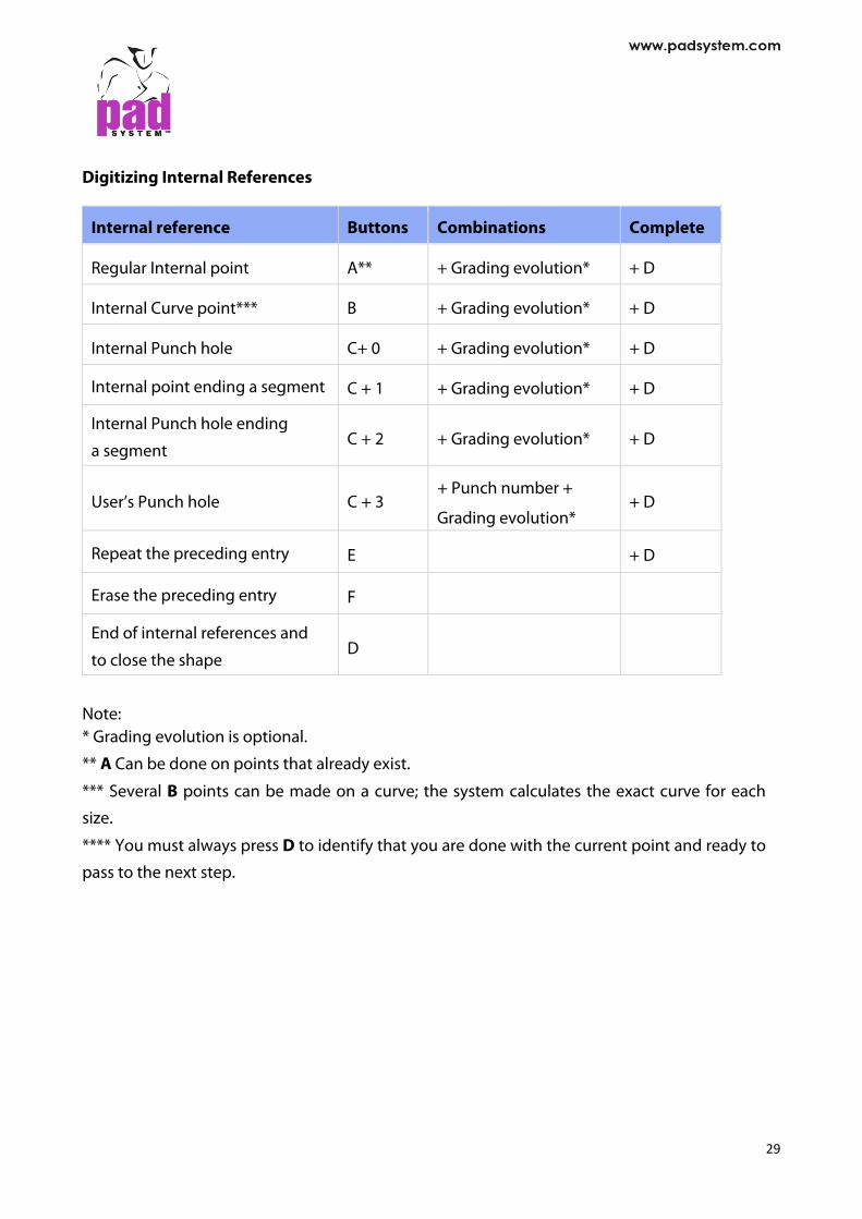
Digitizing Internal References
Internal reference Buttons Combinations Complete
Regular Internal point A** + Grading evolution* + D
Internal Curve point*** B + Grading evolution* + D
Internal Punch hole C+ 0 + Grading evolution* + D
Internal point ending a segment C + 1 + Grading evolution* + D
Internal Punch hole ending
a segment C + 2 + Grading evolution* + D
User’s Punch hole C + 3 + Punch number +
Grading evolution* + D
Repeat the preceding entry E + D
Erase the preceding entry F
End of internal references and
to close the shape D
Note: * Grading evolution is optional.
** A Can be done on points that already exist.
*** Several B points can be made on a curve; the system calculates the exact curve for each
size.
**** You must always press D to identify that you are done with the current point and ready to
pass to the next step.
29

Digitizing/Grading Evolution
PAD System's 16-button puck allows you to enter a graded nest using the digitizing process.
There are four methods that allow you to enter either a regular grading point or an irregular
grading point. Select the one that best suits your needs for each point you digitize. All four
methods can be applied on a pattern piece according to the grading you want to give to each
digitized point. Digitizing Grading Evolutions
Method Grading Button Combinations
00 Regular 0 + 0 + A + A + A + A + D
Description: 0 + 0 Click Medium to identify the Regular method + A Click the Biggest of the Large break + A Click the Biggest of the X-Large break + A Click the Smallest of the Small break + A Click the Smallest of the X-Small break + D When done with the point
Note: the Break sizes must be entered in the following order: Medium, Biggest of Large break, Biggest of X-Large break, Smallest of Small break and Smallest of X-Small break.
01 Irregular 0 + 1 + A + A + A… on all sizes + D
Description: 0 + 1 Click Medium to identify the Irregular method + A Click the Bigger size following the Medium + A Click the next Bigger size. Do the same for all big sizes + A … Until you reach the Biggest size + A Click the Smaller preceding the Medium + A Click the next Smaller size. Do the same for all small sizes+ A … Until you reach the Smallest size + D When done with the point
Note: the sizes must be entered in the following order: Medium, Larger sizes from Medium to the Largest size, the Smaller sizes from the Medium to the Smallest size.
30

Method Grading Button Combinations
02 Progressive (Regular and Irregular)
0 + 2 + D
Description: 0 + 2 Click Medium to identify the Progressive method + D When done with the point The grading of this point is progressive (an average of the grading of the two closest graded points that are on each side of it becomes its grading).
nn Grading library number
Using a Grading library (Regular and Irregular)
1 to 999 + D
Description: 1 to 999 Click Medium and enter # from Grading library + D When done with the point # from Grading Library corresponds to the current opened library
Note: The Grading Library has to be opened before starting the digit process. The first number cannot be 0.
Note: When the point has been entered, you must always press D to identify that you are ready to get to the next point.
31

The 00 Method for Regular Grading
1. First, identify the type of point you want to digitize and enter the corresponding code (refer
to the section about the function of each button and button combination for the 16-button
puck) and select the appropriate code (i.e. A for a regular perimeter point or B for a curve
perimeter point, etc…). Press the button of the Letter corresponding to the type of point.
2. Then 00 on the MEDIUM size to identify the regular grading method used for the point.
3. Then click the A button on each break in the following order:
A on the larger size of the Large group and on the larger size of the Extra-Large group.
A on the smallest size of the Small group and on the smallest size of the Extra- Small group.
4. Complete by clicking the D button to finish digitizing this graded point.
Note: If you intend to add internal information that is attached to the contour to the digitized piece, such as a style line, enter the information on the perimeter where it starts and finishes as you go around the piece.
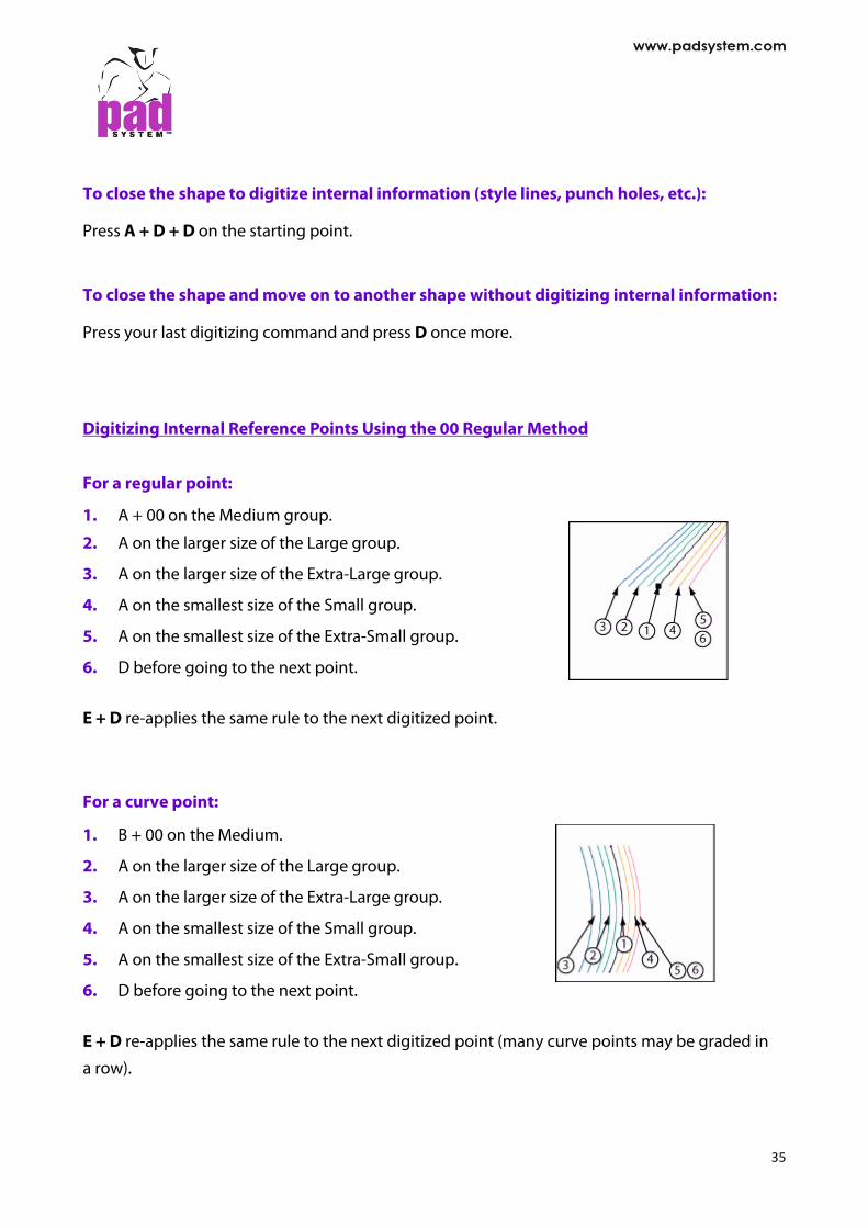
Digitizing Perimeter Points Using the 00 Regular Method For a regular point:
1. A + 00 on the Medium group.
2. A on the larger size of the Large group.
3. A on the larger size of the Extra-Large group.
4. A on the smallest size of the Small group.
5. A on the smallest size of the Extra-Small group.
6. D before going to the next point. E + D re-applies the same rule to the next digitized point.
32

For a curve point:
1. B + 00 on the Medium.
2. A on the larger size of the Large group.
3. A on the larger size of the Extra-Large group.
4. A on the smallest size of the Small group.
5. A on the smallest size of the Extra-Small group.
6. D before going to the next point. E + D re-applies the same rule to the next digitized point (many curve points may be graded in a
row).
For a single notch:
1. C (on the perimeter) on the Medium
2. 1 (on the tip of the notch) + 00 on the Medium.
3. A on the larger size of the Large group.
4. A on the larger size of the Extra-Large group.
5. A on the smallest size of the Small group.
6. A on the smallest size of the Extra-Small group.
7. D before going to the next point. For a double notch:
1. C (on the perimeter) on the Medium.
2. 2 (on the tip of the notch) + 00 on the Medium.
3. A on the larger size of the Large group.
4. A on the larger size of the Extra-Large group.
5. A on the smallest size of the Small group.
6. A on the smallest size of the Extra-Small group.
7. D before going to the next point.
33

For a V notch:
1. C (on the perimeter)
2. 0 (on the tip of the notch) + 00 on the Medium
3. A on the larger size of the Large group.
4. A on the larger size of the Extra-Large group.
5. A on the smallest size of the Small group.
6. A on the smallest size of the Extra-Small group.
7. D before going to the next point.
For a User notch:
1. C (on the perimeter)
2. 3 (on the tip of the notch) + Number of the User notch (in the
notch list) + 00 on the Medium
3. A on the larger size of the Large group.
4. A on the larger size of the Extra-Large group.
5. A on the smallest size of the Small group.
6. A on the smallest size of the Extra-Small group.
7. D before going to the next point.
Do not forget to indicate the direction of the notch when you enter it. To do so:
1. Press C on the perimeter point.
2. Move inside the shape, on the tip of the notch, press 1, 2 or 0 according to the type of
notch desired to identify its length and orientation.
3. Then identify the grading evolution: 00 for regular, 01 for irregular, 02 for progressive or
enter the number from the library. Select F to erase the preceding entry.
34
To close the shape to digitize internal information (style lines, punch holes, etc.): Press A + D + D on the starting point. To close the shape and move on to another shape without digitizing internal information: Press your last digitizing command and press D once more.
Digitizing Internal Reference Points Using the 00 Regular Method For a regular point: 1. A + 00 on the Medium group.
2. A on the larger size of the Large group.
3. A on the larger size of the Extra-Large group.
4. A on the smallest size of the Small group.
5. A on the smallest size of the Extra-Small group.
6. D before going to the next point. E + D re-applies the same rule to the next digitized point.
For a curve point:
1. B + 00 on the Medium.
2. A on the larger size of the Large group.
3. A on the larger size of the Extra-Large group.
4. A on the smallest size of the Small group.
5. A on the smallest size of the Extra-Small group.
6. D before going to the next point. E + D re-applies the same rule to the next digitized point (many curve points may be graded in
a row).
35

For an internal punch hole:
1. C + 0 + 00 on the Medium.
2. A on the larger size of the Large group.
3. A on the larger size of the Extra-Large group.
4. A on the smallest size of the Small group.
5. A on the smallest size of the Extra-Small group.
6. D before going to the next point.
For an internal point ending a segment:
1. C + 1 + 00 on the Medium.
2. A on the larger size of the Large group.
3. A on the larger size of the Extra-Large group.
4. A on the smallest size of the Small group.
5. A on the smallest size of the Extra-Small group.
6. D before going to the next point.
For an internal punch hole ending a segment:
1. C + 2 + 00 on the Medium.
2. A on the larger size of the Large group.
3. A on the larger size of the Extra-Large group.
4. A on the smallest size of the Small group.
5. A on the smallest size of the Extra-Small group.
6. D before going to the next point.
36

For an internal user’s punch hole:
1. C + 3 + 00 on the Medium.
2. A on the larger size of the Large group.
3. A on the larger size of the Extra-Large group.
4. A on the smallest size of the Small group.
5. A on the smallest size of the Extra-Small group.
6.
F
To close the shape and move on to another shape: Press the last digitizing command and press D once more.
37
D before going to the next point.
Select to erase the preceding entry.

The 01 Method for Irregular Grading
1. First, identify the type of point you want to digitize, enter the corresponding code (refer to
the section about the function of each button and button combination for the 16-button
puck) and select the appropriate code (i.e. A for a regular perimeter point or B for a curve
perimeter point, etc…). Press the button of the Letter corresponding to the type of point.
2. Then 01 on the MEDIUM size to identify the irregular grading method used for the point.
3. Then click A on each break in the following order:
Always from the medium up; on all sizes
Then from the medium down; on all sizes
4. Complete by clicking D to finish digitizing this graded point. If you intend to add internal information that is attached to the contour to the digitized piece,
such as a style line, enter the information on the perimeter where it starts and finishes as you go
around the piece.
Digitizing Perimeter Points Using the 01 Irregular Method For a regular point:
1. A-01 on the medium.
2. Then A on each size from the medium to the biggest size.
3. Then A on each size from the medium to the smallest size.
4. D before going to the next point. For a curve point:
1. B-01 on the medium
2. Then A on each size from the medium to the biggest size.
3. Then A on each size from the medium to the smallest size.
4. D before going to the next point.
38

For a single notch:
1. C (on the perimeter) on the medium.
2. (on the tip of the notch) - 01 on the medium
3. Then A on each size from the medium to the biggest size.
4. Then A on each size from the medium to the smallest size.
5. D before going to the next point. For a double notch:
1. C (on the perimeter) on the medium.
2. 2 (on the tip of the notch) -01 on the medium
3. Then A on each size from the medium to the biggest size.
4. Then A on each size from the medium to the smallest size.
5. D before going to the next point. For a V notch:
1. C (on the perimeter)
2. 0 (on the tip of the notch) + 01 on the Medium
3. Then A on each size from the medium to the biggest size.
4. Then A on each size from the medium to the smallest size.
5. D before going to the next point.
For a User notch:
1. C (on the perimeter)
2. 3 (on the tip of the notch) + Number of the User notch (in the notch list) + 01on the Medium
3. Then A on each size from the medium to the biggest size.
4. Then A on each size from the medium to the smallest size.
5. D before going to the next point.
Do not forget to indicate the direction of the notch when you enter it.
39

To do so:
1. Press C on the perimeter point.
2. Move inside the shape, on the tip of the notch, press 1, 2 or 0 according to the type of notch
desired to identify its length and orientation.
3. Then identify the grading evolution: 00 for regular, 01 for irregular, 02 for progressive or
enter the number from the library. Select F to erase the preceding entry. To close the shape to digitize internal information (style lines, punch holes, etc.): Press A + D + D on the starting point. To close the shape and move on to another shape without digitizing internal information: Press the last digitizing command and press D once more.
Digitizing Internal Reference Points Using the 01 Irregular Method For a regular point:
1. A + 01 on the Medium group.
2. Then A on each size from the medium to the biggest size.
3. Then A on each size from the medium to the smallest size.
4. D before going to the next point.
E + D re-applies the same rule to the next digitized point. For a curve point: 1. B + 01 on the Medium.
2. Then A on each size from the medium to the biggest size.
3. Then A on each size from the medium to the smallest size.
4. D before going to the next point.
E + D re-applies the same rule to the next digitized point.
40

For an internal punch hole: 1. C + 0 + 01 on the Medium. 2. Then A on each size from the medium to the biggest size. 3. Then A on each size from the medium to the smallest size. 4. D before going to the next point.
For an internal point ending a segment: 1. C + 1 + 01 on the Medium. 2. Then A on each size from the medium to the biggest size. 3. Then A on each size from the medium to the smallest size. 4. D before going to the next point.
For an internal punch hole ending a segment: 1. C + 2 + 01 on the Medium. 2. Then A on each size from the medium to the biggest size. 3. Then A on each size from the medium to the smallest size. 4. D before going to the next point.
For an internal user’s punch hole: 1. C + 3 + 01 on the Medium. 2. Then A on each size from the medium to the biggest size. 3. Then A on each size from the medium to the smallest size. 4. D before going to the next point.
Select F to erase the preceding entry. To close the shape and move on to another shape: Press the last digitizing command and press D once more.
41

The 02 Method for Progressive Grading 1. First, identify the type of point you want to digitize and enter the corresponding code (refer
to the section about the function of each button and button combination for the 16-button puck) and select the appropriate code (i.e. A for a regular perimeter point or B for a curve perimeter point, etc…). Press the button of the Letter corresponding to the type of point.
2. Then 02 on the position of the point (MEDIUM size if digitizing from a nest) to identify the
progressive grading method used for the point. The grading applied to this point is
proportional to its position and the closest graded points on each side of it no matter what
type of grading method was used for them (not graded, regular grading, irregular grading,
grading from a library). You have several progressive points digitized in a row.
3. Complete by clicking the D button to finish digitizing this graded point.
Note: See the nn Method for Progressive Grading for an example of the 02 Method for Progressive Grading.
The nn Method Grading from the Open Grading Library
Note: To use this method, the Grading library has to be opened before starting the digit process.
4. First, identify the type of point you want to digitize and enter the corresponding code (refer to the section about the function of each button and button combination for the 16-button puck) and select the appropriate code (i.e. A for a regular perimeter point or B for a curve perimeter point, etc…). Press the button of the Letter corresponding to the type of point.
5. Then enter the number of the Grading Library reference (from 1 to 999) you want to apply on the position of the point (MEDIUM size if digitizing from a nest). The grading applied to this point is the one corresponding to the number in the open library. The library number cannot start with 0, it has to be from 1 to 999.
6. Complete by clicking D to finish digitizing this graded point.
42

Example:
43

Digitizing with the Digi-Pen (Algotex Digi-Pen 4) The Digi-Pen is used to enter contour points and internal references on the pattern piece. To use the Digi-Pen digitizer, go to the Options menu, select Device Configurations…. Choose
Algotex Digi-Pen 4 from the list of compatible digitizers. Before starting the digitizing process, purge the Digi-Pen of any information it may contain.
Firstly, select Digitize tool in the Pattern application. Secondly, press with the tip of pen, on
the End Process button in the bottom-right corner of Algotex paper. Finally, put the pen in
its holder. If there is information in the pen, it shows on the screen. Delete it if you do not need it. To start digitizing, set your working area view to 20% (you can use the bottom-left corner zoom
button to do so). Select the digitize tool and click the bottom-left corner of working area.
The pattern piece must be placed under the Algotex paper. The numeric buttons around the Algotex paper allow to enter regular and curve points,
contour points and internal regular points. Just click the buttons with the tip of pen to select
the code corresponding to the type of point for digitizing. The codes are described in the
next page. The pen stores the selected type of point until another type of point is selected, so you can
enter several consecutive points of the same type just by clicking around the pattern shape.
Press the End Process square-shaped button before putting the pen back to the holder to
transfer the information from pen to PAD application.
If the Digitize tool had been selected, the pieces appear on the screen. On the other hand, if
the Digitize tool is not selected and the pen is in its holder, the digitized piece keeps in memory.
When choosing the Digitize tool next time, the following window shows, allowing to import the
digitized piece.
44

Import: the digitized information shows on screen. Delete: the digitized information is destroyed. Cancel: the digitized information keeps in memory for later use but does not appear on screen
as though the Digitize tool had not been selected.
Digi-Pen button functions:
Button Contour
1 Enter a regular contour point.
2 Enter a curve contour point. (Several points can be made on a curve; the system calculates the exact curve.)
3 Internal regular point.
4 Finish with the current piece and enter another pattern piece without returning to the screen.
Digitizing a piece with the Digi-Pen:
45

Digitizing using the Digi-Pen with Extended Capabilities
To select Digi-Pen with extended capabilities, go to the Options menu, select Device Configurations…. Select Algotex Digi-Pen 4 in the list of digitization options and check the Extended Capabilities(4 Buttons) box.
Digi-Pen digitization with extended capabilities allows you to digitize contour points (such as curve points, regular points and default PAD System notches) plus internal references (such as style lines, pocket lines and punch holes). The process is the same as for the basic use of Digi-Pen, but refer to the following chart of numerical codes to select the type of points for digitizing.
Digi-Pen with Extended Capabilities Button Functions for the Perimeter of the Piece:
Button Perimeter
1 Enter a regular contour point.
2 Enter a contour curve point (several #2 points can be made on a curve; the system calculates the exact curve).
3 + 1* Enter a single notch. Click 3 on the perimeter, click 1 for the length and orientation of the notch.
3 + 2* Enter a double notch. Click 3 on the perimeter, click 2 for the length and orientation of the notch.
3 + 3* Enter a V notch. Click 3 on the perimeter, click 3 again for the length and orientation of the notch.
4 Finish the contour. You are ready to enter the piece internalreferences.
4 + 4 Finish with the piece and enter another pattern piece if you do not need any internal references for it.
Note: * You can digitize only one notch at a time. After positioning the notch, the Digi- Pen reverts to the last type of point digitized. For instance, if your notch was preceded by a regular curve point, the Digi-Pen returns to the regular curve point mode after having digitized the notch.
46

Digi-Pen with Extended Capabilities Button Functions for Internal References:
Button Perimeter
1 Enter a regular internal point or beginning of a segment regular point.
2 Enter an internal curve point. (Several #2 points can be made on a curve; the system calculates the exact curve).
3 + 1 Enter an internal punch hole.
3 + 2 Enter an internal point ending a segment.
3 + 3 Enter an internal punch hole ending a segment.
4 To indicate that you finish entering internal references and are ready to start another piece.
4 + 4 Finish with the piece and enter another pattern piece if you do not need any internal references for it.
47

Digitizing Information in Pieces View Using the Fictitious Keyboard
Digitizing in Pieces View allows you to enter simultaneously a range of piece information using
the fictitious keyboard with the digitizing table. Below are the two commands that you need
to use with the fictitious keyboard, which can vary depending of your digitizing device.
Command 4-button
puck and
Digipen
4-button puck(1-2-4-8)
GTCO 16-button puck
Enter information #2 #2 Yellow #2
End process #4 #8 Blue D
To digitize a piece with its Piece information:
1. Make sure that you are digitizing in Pieces View (Option menu- Device Configurations…
check the Digitize in Pieces View option).
2. Reduce the zoom level of working area to 20% (in the lower left corner of window).
3. Select the Digitize tool and click the lower left corner of the working area.
4. If you are using a 16-button puck, enter the grain line first (A-D left side; A-D right side).
5. Use the Enter Information command (refer to the chart above), click the origin of the fictitious keyboard located in its lower left corner. This activates the Piece information entry.
48

6. Still using the Enter Information command, enter the piece information (i.e.: pattern #, piece name, etc.) by clicking the keyboard simulation of the digit table. When using a puck, press the button for every character. With the Digi-Pen, press the Enter Information command once. You can enter the information by pressing on each key with the tip of the pen.
7. When completed, press anywhere using the End Information command.
8. Proceed in the usual manner to digitize the pattern piece. Repeat the above steps for each piece.
49

Execute Menu: Finish The Finish item in the Execute menu allows user to end the digitizing process and input the file name. To end the digitizing process and input the file name:
1. Select Finish in the Execute menu. A dialog box appears.
2. Input the file name and click OK button to validate.
50

Options Menu
Options Menu: Language
The Language in Options menu allows to choose language. It will translate the application to the selected language. Choose Auto from the list, the language will be shown according the language of operating system.
Options Menu: Unit
The Unit in the Options menu allows user to select the desired measurement unit (Centimeter or Inch).
51

Options Menu: Device Configurations…
The Device Configurations item is to obtain the Digitizer dialog box. From the digitizer list, select the desired drivers for your peripherals and the corresponding COM Port (Windows / Linux) / Serial Port (Macintosh) required for the connection.
Note: You may require a Keyspan adapter.
To configure digitizer driver: 1. Select Options, Device Configuration, a dialog box appears as below:
52

2. Press Add… button to choose the digitizer which is ready to connect to Digitizer Manager.
Choose the appropriate driver and press “Next” button to continue.
Support Digitizer Drivers
Brand Model
Algotex Digi-Pen 4
GTCO Calcomp 2000 (AM5) 9500 format 4 DrawingBoard III DrawingBoard III 16 Digi-PAD 5 Roll-Up II 16 Super L II Plus
Numonics 2200 GGT 2200 GGT 16 2200 GGT 16(1) Numonics BidMate 4 Numonics BidMate 16
PAD System PAD System 4 PAD System 16
Summagraphic Summa MicroGrid Summagrid V 16
53

3. Configure the port setting COM Port (Windows / Linux) / Serial Port (Macintosh) if necessary.
Baud Rate: 2400, 4800, 9600, 19200 or 38400 bauds. Data Bits: 7 or 8 data bits. Parity: EVEN, ODD or NONE. Stop Bits: 1, 1.5 or 2 data bits.
Check / Uncheck the option on Enable Software Flow Control. Check / Uncheck the option on Enable Hardware Flow Control.
Then press “Next” button to continue.
4. Configure the desired digitizer setting if necessary. Then press “Finish” to execute the function.
54

Resolution: The units are LPI (Lines per Inch) and LPMM (Lines per Millimeter). The most common values are:
VALUE UNIT VALUE UNIT
1250 LPI 1000 LPMM
1000 LPI 500 LPMM
500 LPI 100 LPMM
200 LPI 50 LPMM
100 LPI 40 LPMM
20 LPMM
10 LPMM
8 LPMM
4 LPMM
1 LPMM
55

Report Format: The main problem is that the report format is different for each digitizer. To
extract information from the report, the driver needs to locate it properly. Report Length: The minimum report length is 3 characters and the maximum length is 30
characters. It is very important to calculate carefully the report length, i.e. the length of the
character string received from the digitizer. If the report length is incorrect, the driver will not
work. Information included in this report:
Button ID number or character
X coordinate
Y coordinate
Decimal point
Sign
Carriage return
Line feed
Other (Unused information)
Click & select the appropriate value in the pop-up menu to set each character type for the report.
56
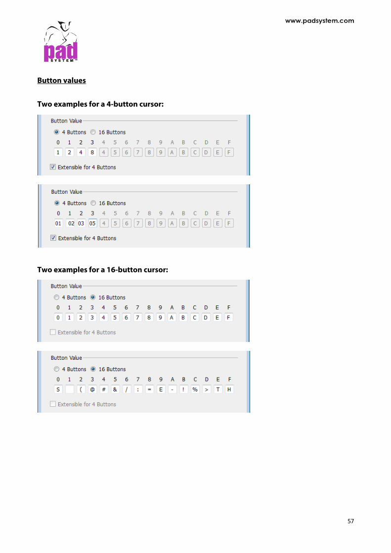
Button values
Two examples for a 4-button cursor:
Two examples for a 16-button cursor:
57

The selected driver is displayed to the Digitizer dialog box.
Configure…: To change the setting on the selected driver. Press Configure button to change the setting or choose another plotter driver. *By double clicking the selected driver, user can get the same windows as the Digitizer Configuration Wizard window.
Remove: To remove the selected driver. Press Remove button to remove the selected digitizer driver.
Digitizer Port: To configure the port setting COM Port (Windows / Linux) / Serial Port (Macintosh).
Extended Capabilities (4 Buttons): To extend function for the 4 buttons of the cursor.
Digitize in Pieces View: By default, the pieces are digitized in Plan View. To digitize pieces in Piece View, check this box.
View Digitized Points: To view a template point for the points in working area. This helps user to verify the precision of curves.
High Precision Curves: To produce a larger number of curves, resulting in smoother curves.
58

Options Menu: Connection Settings
The Connection Settings in Options menu allows you to connect the digitizer through TCP/ IP (LAN), Wireless.
Port: Take the TCP/IP Port number automatically.
Account: User name of the digitizer
Click OK to execute.
59

Options Menu: Piece Name List… To speed up the process of identifying pattern pieces, user can keep a list of the most commonly
used pieces. Establish this list by selecting the Piece Name List... in the Options menu. This list is available in the Piece Info dialog boxes, thus making it easy to build and access a list of the most frequently used piece names. The Piece Name List dialog box shows:
Add: Adds a new blank piece name to the end of the list. The piece name must be entered to
the new blank in the list. Insert: Inserts a new blank piece name before the selected piece name. The piece name must
be entered in the text field at the bottom of dialog box. Remove: Removes the selected piece name(s) from the Piece Name List. Copy: Copies data from the Piece Name List to the clipboard. You can copy the content of the
clipboard to a local or an external destination (a database or word processing application). Paste: Pastes data from the clipboard to the list. The content of the clipboard can be from a
local or an external destination (a database or word processing application).
To enter or replace a piece name: Select the corresponding entry in the list and Type the name in. The name of pieces that already existed can be replaced by a new data group if they are selected before executing the paste command.
60

Options Menu: Reference Code List... Reference Code List... allows user to create or modify a reference code list. This list is available in the Piece Info dialog boxes, thus making it easy to build and access a list of the most frequently used reference codes.
Select the Reference Code List... function under the Options menu.
A dialog box shows:
Add: Adds a new reference code entry at the end of the list. The reference code must be entered to the new blank in the list.
Insert: Includes a reference code entry above the selected reference code. The reference code must be entered in the text field at the bottom of the dialog box.
Remove: Removes the selected reference code(s) from the Reference Code List.
Copy: Copies data from the Reference Code List to the clipboard. You can copy the content of the clipboard to a local or an external destination (a database or word processing application).
Paste: Pastes data from the clipboard to the list. The content of the clipboard can be from a local or an external destination (a database or word processing application).
61

Options Menu: Fabric List… Fabric List... allows to create or modify a new Fabric List. This list is available in the Piece Info dialog boxes, thus making it easy to build and access a list of the most frequently used fabrics.
Select the Fabric List function under the Options menu. A dialog box shows:
Add: Adds a new fabric entry to the end of the list. The fabric name must be entered to the new blank in the list.
Insert: Inserts a fabric entry above the selected fabric name. The fabric name must be entered in the text field at the bottom of the dialog box.
Remove: Removes the selected fabric(s) from the fabric list.
Copy: Copies data from the Fabric List to the clipboard. You can copy the content of the clipboard to a local or an external destination (a database or word processing application).
Paste: Pastes data from the clipboard to the list. The content of the clipboard can be from a local or an external destination (a database or word processing application).
62

User can easily replace fabric names that already exist with a new data group, provided to select the fabric names to be replaced before executing the paste command. User can replace a fabric name at any time by selecting and changing it via the text box. User can easily change the fabric color by selecting the name of the color. A color chart appears and allows choosing another color from the chart.
63

Options Menu: Notch List… Digitizer Manager offers three types of system Notches: the Simple Notch, the Double Notch and the V Notch.
Select the Notch List... function in the Options menu to create new notch types. A dialog box appears:
New: Creates a new Notch.
Remove: Removes a Notch from the list. You can easily modify the characteristics of the selected notch. Type in the new data to the page of Notch Characteristics and press OK button to validate the function.
64

Creating a Notch
Click the New button in the Notch List. The Notch List dialog box opens. The Notch List dialog box offers the following options:
Notch Number: Automatic creates a number for the new notch. It identifies the notch during the 16-button digitization process. Change the notch rank from the list. Select the punch hole and press the Up or Down Arrow.
Notch Name: Identifies each notch with a particular name. You can use three measurements to define a Notch:
Depth: Identifies the length of the interior (positive value) or exterior (negative value) of the shape.
Width Perimeter: Identifies the width of notch on the perimeter of the shape.
Inside Width: Identifies the width of notch at its internal end.
The full scale notch is shown to the right according to the values entered in the text fields. The maximum value accepted for the measurement of a notch is 1 inch (2.54 cm).
65

Options Menu: Punch Hole List… Digitizer Manager offers punch hole characteristic and allows to create new types of punch holes.
Select Punch Holes List… in the Options menu. The Punch Hole List dialog box appears:
New: Creates a new punch hole.
Remove: Clears a punch hole from the list. You can easily modify the characteristics of the selected punch hole. Type in the new data to
the page of Punch Hole Characteristics and press OK button to validate the function.
66

Creating a Punch Hole Click the New button. The Punch Hole Characteristics dialog box appears:
Punch Hole Number: Automatic creates a number for the new punch hole. It identifies the punch hole during the 16-button digitization process. This number determines the position of the punch hole in the Punch Hole sub-menu of the Treatment menu. Change the punch hole rank from the list. Select the punch hole and press the Up or Down Arrow.
Punch Hole Name: Identifies each punch hole with a unique name. To create personalized punch holes, use the ten forms in combination with various measurements. The full scale punch hole appears in the bottom-right corner according to the values entered in the text fields. Changes are made when you exit the dialog box by clicking the OK button. The maximum value accepted for the measurement of a Punch Hole is 1 inch (2.54 cm). Click the OK button to confirm the punch hole.
67

Options Menu: Show Job List
The Show Job List in the Options menu allows user to show or hide the job list.
Select Show Job List, the check mark () is displayed next to the item.
See the Digitizer Manager Basics chapter for more information about the Job List.
68

View Menu
View Menu: Zoom
The Zoom in the View menu allows user to select from the menu a preset visualization of the working area or a customized zoom level. The zoom level can be set at any value between 0.5% and 2000%.
Global View: Displays all the pattern pieces on screen, regardless of their position on the working area.
On Selection: Zooms on the selection and displays it in the center of screen. It is available if one or more pieces are selected.
Click the Zoom Out/Zoom In icons to obtain preset zoom views based on the screen resolution.
These options are available in the Zoom Menu as well, which is located at the bottom left side of the Digitizer Manager. For further details, refer to the Basics chapter of this user manual.
69

Grade Menu
Grade Menu: Working Sizes… At first, the Grading working size is always set at one size by default, which is the base size.
There are two ways to create a grade nest with multiple sizes: you can either use the Change… button or the Generate… button in the Grading Working Sizes dialog box. To open the Grading Working Sizes dialog box, open the Grade menu and select Working Sizes...
The Grading Working Sizes dialog box opens:
70

To create a new Grading nest using the Change… button: 1. Press Change... button to open the Change Grading Nest information dialog box. 2. In the text box, enter the number of sizes needed for a particular style, including the
medium size (base). Or press the arrow next to the text box to scroll up or down.
3. Press the OK button to validate the information.
Establishing Different Grading Evolutions and Sizes Five regular breaks are available for grading. The default names are X-Small, Small, Medium (being the base size), Large and X-Large.
Establishing Size List
In the Grading Working Sizes dialog box, select (highlight) the first item in the list and change the number in the Size text box to the smallest desired size. In the same manner, repeat the procedure for all the other items in the list until the last one, which would be the biggest size. If user does not work with numerical sizes, use special names (alphanumerical sizes) in the
Special text box to identify the label of each size.
71

Setting the Size Break In the size list, identify the size corresponding to the base pattern. The base size must be set at break medium.
Modify the other size breaks according to the grading group.
Locking the Medium size To lock the medium size to forbid future modifications, check the Lock medium size box. The grading of medium size will be removed. Uncheck the Lock medium size box to unlock. If user locks the medium size, a warning massage shows up that all the changes made to the medium size will be lost and asks whether to continue.
72

To create a new Grading Nest using the Generate… button 1. Click Generate… button in the Grading Working Sizes dialog box. 2. The Generate Grading Nest dialog box opens.
3. Set the Medium Size by entering the size that represents the medium break (the base size)
into the Medium Size text box.
4. Input the number of sizes for each break size (Amount), and enter the size interval between each size (Interval). User can see a preview of the resulting size to the right of the window.
5. Click OK button to save the new grading nest. 6. Special names can be added afterwards; refer to Establishing Size List in the previous
section.
73

Insert button
The Insert button enables user to insert a new size, anywhere within the grading nest.
To Insert a new size in the Grading nest: 1. In the size window in Grading Working Sizes dialog box, highlight the place in the grading
list above which would like to add a new size.
2. Click the Insert button. 3. A new size appears above the size that you highlighted. 4. Click OK button to save changes. Add button
The Add button adds a new size at the end of the grading nest.
To add a new size at the end of the Grading nest: 1. Click Add button in the Grading Working Sizes dialog box. 2. A new size appears at the end of the grading nest list. 3. Click OK button to save changes. Remove button
The Remove button deletes a selected size from the grading nest.
To remove a size from the grading nest: 1. In the size window in Grading Working Sizes dialog box, highlight the size to remove. 2. Click the Remove button. 3. The selected size is deleted from the grading nest list. 4. Click OK button to save changes.
74

Color When creating multiple sizes for the same break (for example, several size breaks “small”), user
can use the Color feature in the Grading Working Sizes dialog box to assign a unique color to each size. In the grading nest, each size within the same break group can appear as a different color.
1. Click the color box next to the size.
2. Select the color you wish to use from Operating System’s color picker. 3. Repeat these steps to add unique colors to the other sizes user wish to customize. The
grading nest shows all sizes in the selected colors.
75

Grading Nest List
Instead of going through the same process again, user can save the Grading Working Sizes information and reuse it for another pattern file if the same nest is required.
Press the List button in the Grading Working Sizes dialog box. A second dialog box opens where the previously saved grading nest information is listed (if any):
To register the current grading working sizes to the Grading Nest List: 1 Press Add button. 2 Enter the name of the current grading nest. 3 Click OK button.
This grading nest appears in the Grading Nest List dialog box.
Buttons in the Grading Nest List dialog box offer the following options. Remove: To delete the selected grading nest from the list.
76

To select a grading working nest in the Grading Nest List 1 Press List button in the Grading Working Sizes dialog box. 2 The Grading Nest List selection window appears. Highlight the desired grading working
nest from the list.
3 Click Open button. 4 Then it will apply the desired grading nest list to the main window of Grading Working
Sizes.
77

Chapter 3 . . . . . . . . Digitizer Driver Preference Digitizer driver allows users to work with any kind of digitizer that sends ASCII reports. Most digitizers can send ASCII reports, but a few can only send binary reports.
Parameter Extraction Extracting the digitizer parameters: The digitizer must be set up in point mode, i.e. it must send the report only but not a continuous stream of reports when a button is released on the digitizer cursor. The user must use a telecommunication program, such as HyperTerminal (Windows) / MacTerminal (Macintosh). These programs allow you to see the report format sent by the digitizer to the computer. In the telecommunication program, set up the communication parameters, i.e. baud rate, data bit, stop bit, parity and communication port (Modem or Printer for Mac/Com1, Com2, Com3 or Com4 for PC). The values for these communication parameters must be the same for the digitizer and the telecommunication program. Often, it is necessary to try many values to discover the correct parameter values for the digitizer.
The most frequent values used for the baud rate are 9600, 2400 and 1200. The most frequent values used for the stop bits are 1 and 2. Press any button on the digitizer cursor to test the communication parameters. For example, the digitizer Summagrid has sent these 16 valid reports by using a 16- button cursor.
78

Cursor button pressed Report sent by the digitizer to the terminal 1 2 3 4 5 6 7 8 9 0 A B C D E F
+1179.550,+0489.475,01,0 +1179.575,+0489.475,02,0 +1179.550,+0489.475,03,0 +1179.550,+0489.475,04,0 +1179.550,+0489.475,05,0 +1179.550,+0489.475,06,0 +1179.575,+0489.475,07,0 +1179.550,+0489.475,08,0 +1179.575,+0489.475,09,0 +1179.250,+0489.475,16,0 +1179.275,+0489.475,10,0 +1179.250,+0489.475,11,0 +1179.250,+0489.475,12,0 +1179.250,+0489.475,13,0 +1179.250,+0489.475,14,0
+1179.225,+0489.475,15,0
79

Problem: The terminal is receiving continuous information from the digitizer.
Solution: This means that the digitizer is not set up to point mode. Switch the digitizer to point mode.
Problem: Information received from the digitizer is not readable.
Solution: The digitizer is set up in binary mode, i.e. not in ASCII mode. Switch the digitizer to ASCII mode.
Problem: The communication parameters of the telecommunication software are not properly set up for your digitizer.
Solution: Check the settings of the telecommunication software. If you do not receive any information from the digitizer, then the communication parameters of the telecommunication software are not properly set up for your digitizer. Check the settings of the telecommunication software, i.e. baud rate, data bit, stop bit, parity.
Problem: Using the wrong serial port.
Solution: Use the serial port the digitizer is connected to.
Problem: There is another application using the same serial port.
Solution: Close this application.
Problem: The digitizer is not sending any information.
Solution: The digitizer needs to be repaired.
Problem: Using the wrong cable.
Solution: Contact the service department to obtain a proper cable.
80

Identifying a similar driver Once the terminal receives a correct report from the digitizer, look in the list of PAD System digitizer drivers to find a driver that uses similar parameters. If you find a perfect match, select the driver from the PAD System digitizer drivers’ list in the
Device Configurations dialog box in the Option menu. If there is no perfect match, set and use the generic digitizer driver for 4 or 16 buttons.
Setting up the generic digitizer driver: Communication Parameters Set the communication parameters, i.e. the baud rate, the data bits, the parity and the stop bits. The values must be the same as the values used in the terminal.
Resolution Set the resolution, i.e. the resolution value and the resolution unit. The resolution is often very difficult to calculate precisely. You will need to set up the driver, digitize a perfect square and verify if the size of the square is good.
If the square is too big, increase the resolution value or change the resolution unit. If the square is too small, decrease the resolution value or change the resolution unit.
Report
Set the report values, i.e. the report length and the report format. Be careful when calculating the report length, because you may have to count one or two invisible characters at the end of the report, i.e. the carriage return and the line feed. You must set a valid report format.
81

BUTTON NUMBER: Minimum 1 character Maximum 3 characters Consecutive characters only
X AND Y COORDINATES: Minimum 1 character The same number of characters is required Consecutive characters or separated by one decimal point If sign, then only before the coordinate If decimal point, then NOT before the coordinate
SIGN AND DECIMAL POINT: Minimum 0 character Maximum 2 characters
CARRIAGE RETURN AND LINE FEED Minimum 0 character Maximum 1 character DO NOT FORGET TO COUNT THE CARRIAGE RETURN AND THE LINE FEED CHARACTERS WHEN CALCULATE THE REPORT LENGTH. THE PRESENCE OF THESE TWO CHARACTERS CAN BE IDENTIFIED BY THE WAY THE REPORT (STRING) WILL APPEAR ON SCREEN.
Carriage return + Line feed Carriage return ONLY
AAAAA CCCC
BBBBB
CCCCC The previous string is overwritten by the current string.
82

Line feed ONLY Carriage return ONLY
AAAAA CCCCC
BBBBB
CCCCC The previous string is overwritten by the current string.
Button Values Each button value must be unique. The number of characters used for each button value must be the same as the number of characters used in the report format of the generic digitizer driver for button values.
83

Appendix A PAD System Software License Agreement . . . . . . . .
PAD System International Limited Software License PLEASE READ THIS SOFTWARE LICENSE AGREEMENT ("LICENSE") CAREFULLY. BY CLICKING "Yes", YOU ARE AGREEING TO BE BOUND BY THE TERMS OF THIS LICENCE. IF YOU DO NOT AGREE TO THE TERMS OF THIS LICENCE, OR IF YOU PURCHASED OR OBTAINED THE PAD SYSTEM SOFTWARE FROM AN UNAUTHORISED REPRESENTATIVE OF PAD SYSTEM INTERNATIONAL LIMITED, CLICK "No" AND (IF APPLICABLE) RETURN THE PAD SYSTEM SOFTWARE TO THE PLACE WHERE YOU OBTAINED IT FOR A REFUND. 1. License. The software, documentation and materials accompanying this License whether on disk, in read only memory, on any other media or in any other form (the "PAD System Software") are licensed to you by PAD System International Limited. You own the media on which the PAD System Software is recorded but PAD International Limited is the owner of the PAD System Software. The PAD System Software in this package and any copies which this License authorizes you to make are subject to this License. 2. Permitted Uses and Restrictions. This License allows you to install and use the PAD System Software on a single computer(s) with the appropriate hardware protection device provided at the time of initial purchase of PAD System software upon the terms and subject to the conditions contained herein. This License does not allow the PAD System Software to be loaded, installed or used on any other computer. You may make one copy of the PAD System Software in machine readable form for backup purposes only. The backup copy must include all copyright information contained on the original. Except as expressly permitted in this License, you may not decompile, reverse engineer, disassemble, modify, rent, lease, loan, sublicense, distribute or create derivative works based upon the PAD System Software in whole or part. This license allows you to install or operate the PAD System Software only on a computer system with the appropriate hardware protection device. THE PAD SYSTEM SOFTWARE IS NOT INTENDED FOR USE IN THE OPERATION OF NUCLEAR FACILITIES, AIRCRAFT NAVIGATION, COMMUNICATION SYSTEMS, OR AIR TRAFFIC CONTROL MACHINES IN WHICH CASE THE FAILURE OF THE PAD
84

SYSTEM SOFTWARE COULD LEAD TO DEATH, PERSONAL INJURY, OR SEVERE PHYSICAL OR ENVIRONMENTAL DAMAGE AND PAD SYSTEM INTERNAITONAL Limited WILL NOT BE LIABLE FOR ANY DAMAGES OR LOSSES SO CAUSED. This Licence will terminate automatically without notice from PAD System International if you fail to comply with any term(s) of this License. 3. Proprietary Rights. You acknowledge that the PAD System software and related materials provided by PAD System International Limited are the exclusive property of PAD System International Limited and said materials are furnished solely to assist you in the installation, operation and use of the PAD System software. The only right which obtains from purchasing the PAD System software and related materials is the right of use in accordance with the terms and conditions of this License. Title to or ownership of all applicable rights in patent, copyright, trademark and trade secrets in PAD System software and related materials shall remain exclusively with PAD System International Limited. 4. Limited Warranty on Media (if applicable). PAD System International Limited warrants the media on which the PAD System Software is recorded to be free from defects in materials and workmanship under normal use for a period of ninety (90) days from the date of original retail purchase. Your sole remedy under this provision shall be, at PAD System International Limited's discretion, a refund of the purchase price of the product containing the PAD System Software or replacement of the PAD System Software when returned to PAD System International Limited or a PAD System International Limited's authorized representative with a copy of a valid purchase receipt. A valid purchase receipt means a receipt issued by an authorized representative of PAD System International Limited. THIS LIMITED WARRANTY AND ANY IMPLIED WARRANTIES ON THE MEDIA INCLUDING THE IMPLIED WARRANTIES OF MERCHANTABILITY AND FITNESS FOR A PARTICULAR PURPOSE ARE LIMITED TO A PERIOD OF NINETY (90) DAYS FROM THE DATE OF ORIGINAL RETAIL PURCHASE. SOME JURISDICTIONS DO NOT ALLOW LIMITATIONS ON HOW LONG AN IMPLIED WARRANTY LASTS, SO THIS LIMITATION MAY NOT APPLY TO YOU.TO THE EXTENT PERMITTED BY APPLICABLE LAW, PAD SYSTEM INTERNATIONAL LIMITED SPECIFICALLY DISCLAIMS ALL OTHER WARRANTIES ON THE MEDIA , WHETHER VERBAL OR WRITTEN, EXPRESS OR IMPLIED. 5. Disclaimer of Warranty on PAD System Software. You expressly acknowledge and agree that use of the PAD System Software is at your sole risk. The PAD System Software is provided "AS IS" and without warranty of any kind and PAD System International LIMITED EXPRESSLY DISCLAIMs ALL WARRANTIES AND/OR CONDITIONS, EXPRESSED OR IMPLIED, INCLUDING, BUT NOT LIMITED TO, THE IMPLIED WARRANTIES AND/OR CONDITIONS OF MERCHANTABILITY OR SATISFACTORY
85

QUALITY AND FITNESS FOR A PARTICULAR PURPOSE AND NONINFRINGEMENT OF THIRD PARTY'S RIGHTS. PAD SYSTEM INTERNATIONAL LIMITED DOES NOT WARRANT THAT THE FUNCTIONS CONTAINED IN THE PAD SYSTEM SOFTWARE WILL MEET YOUR REQUIREMENTS, OR THAT THE OPERATION OF THE PAD SYSTEM SOFTWARE WILL BE UNINTERRUPTED OR ERROR-FREE, OR THAT DEFECTS IN THE PAD SYSTEM SOFTWARE WILL BE CORRECTED. FURTHERMORE, PAD SYSTEM INTERNATIONAL LIMITED. DOES NOT WARRANT OR MAKE ANY REPRESENTATIONS REGARDING THE USE OR THE RESULTS OF THE USE OF THE PAD SYSTEM SOFTWARE OR RELATED DOCUMENTATION IN TERMS OF THEIR CORRECTNESS, ACCURACY, RELIABILITY, OR OTHERWISE. NO ORAL OR WRITTEN INFORMATION OR ADVICE GIVEN BY PAD SYSTEM INTERNATIONAL LIMITED OR A PAD SYSTEM INTERNATIONAL LIMITED'S AUTHORIZED REPRESENTATIVE SHALL CREATE A WARRANTY OR IN ANY WAY WIDEN THE SCOPE OF THIS WARRANTY. SHOULD THE PAD SYSTEM SOFTWARE PROVE DEFECTIVE, YOU (AND NOT PAD SYSTEM INTERNATIONAL LIMITED OR ITS AUTHORIZED REPRESENTATIVE) ASSUME THE ENTIRE COST OF ALL NECESSARY SERVICING, REPAIR OR CORRECTION. SOME JURISDICTIONS DO NOT ALLOW THE EXCLUSION OF IMPLIED WARRANTIES, SO THE ABOVE EXCLUSION MAY NOT APPLY TO YOU. PAD SYSTEM INTERNATIONAL LIMITED SHALL BE UNDER NO LIABILITY TO YOU WHATSOEVER IN RESPECT OR THE PAD SYSTEM SOFTWARE IF YOU PURCHASED OR OBTAINED IT FROM AN UNAUTHORISED REPRESENTATIVE OF PAD SYSTEM INTERNATIONAL LIMITED. THE TERMS OF THIS DISCLAIMER DO NOT AFFECT OR PREJUDICE THE STATUTORY RIGHTS OF A CONSUMER ACQUIRING PAD SYSTEM INTERNATILNA LIMITED'S PRODUCTS OTHERWISE THAN IN THE COURSE OF A BUSINESS, NEITHER DO THEY LIMIT OR EXCLUDE ANY LIABILITY FOR DEATH OR PERSONAL INJURY CAUSED BY PAD SYSTEM INTERNATIONAL LIMITED'S NEGLIGENCE. 6. Limitation of Liability. UNDER NO CIRCUMSTANCES, INCLUDING NEGLIGENCE, SHALL PAD SYSTEM INTERNATIONAL LIMITED. BE LIABLE FOR ANY INCIDENTAL, SPECIAL, INDIRECT OR CONSEQUENTIAL DAMAGES ARISING OUT OF OR RELATING TO THIS LICENSE. SOME JURISDICTIONS DO NOT ALLOW THE LIMITATION OF INCIDENTAL OR CONSEQUENTIAL DAMAGES SO THIS LIMITATION MAY NOT APPLY TO YOU. In the event that any exclusion contained in this provision shall be held to be invalid for any reason and PAD System International Limited becomes liable for loss or damage that may lawfully be limited, such total liability to you for all damages shall not exceed the amount of [ one thousand Hong Kong dollars (HK$1.000.00)]. 7. Term and Termination. PAD System International Limited shall have the right to terminate this Licence if you fail to comply with the terms and conditions herein contained. PAD System International Limited shall give written notice to you of such defaults and if such defaults have
86

not been cured within thirty (30) days after such notice, then PAD System International Limited shall be entitled, in addition to any other rights it may have under this Licence or in law, to terminate this Licence. You agree, upon expiration of the term of the present Licence or upon termination by reason of your default, to immediately return or destroy the PAD System software and copies thereof and related materials as directed by PAD System International Limited and, if requested by PAD System International Limited, to certify in writing as to the destruction or return of the PAD System Software and all copies thereof. 8. Compliance. You agree that PAD System International Limited may perform such tests as PAD System International Limited shall deem necessary to monitor compliance with this Licence at any time, with or without notice, during normal business hours. 9. Controlling Law and Severability. This License shall be governed by the laws of Hong Kong SAR. If for any reason a court of competent jurisdiction finds any provision, or portion thereof, to be unenforceable, the remainder of this License shall continue in full force and effect. 10. Complete Agreement. This License constitutes the entire agreement between the parties with respect to the use of the PAD System Software and supersedes all prior or contemporaneous understandings regarding such subject matter. No amendment to or modification of this License will be binding unless in writing and signed by PAD System International Limited. PAD SYSTEM INTERNATIONAL LIMITED
87

Appendix B About PAD System International Limited . . . . . . . . PAD System was founded in 1988, in Montreal Canada by creative people from the apparel industry. A leader in CAD/CAM integrated solutions and dedicated to the apparel, textile and leather industry, PAD System is present on all five continents through its international distribution network. Today PAD System is active in more than 50 countries and available in 8 languages. From virtual design to integrated production, PAD System and its partners provide service, support and training to thousands of satisfied customers worldwide—from freelancers to large scale producers. With a complete design suite—pattern, placement, production—the software offered by PAD System represents a set of cutting-edge modules that are complete, coherent, and compatible with the competition. PAD System software may also be used with the majority of standard peripherals on the market, such as digitizing tables, plotters, automated knives and even scanners. PAD System's mission is to produce complete, high-tech CAD/CAM solutions that are simple, efficient and flexible for companies and individuals working in the clothing, textile, and leather industries, as well as the 3D graphic design industry.
88

89
PAD System™ International Limited (Head Office) Unit B & D, 11/F, Gee Hing Chang Industrial Bldg, 16 Cheung Yue Street, Cheung Sha Wan, Kowloon, Hong Kong Tel: (852) 2370-9178 Fax: (852) 2370-9085 [email protected] http://www.padsystem.com/ Other countries: Please locate the distributor near to you by consulting our website: www.padsystem.com, distributors section.