page 1 18m recharge upgrade kit installation guide
TRANSCRIPT
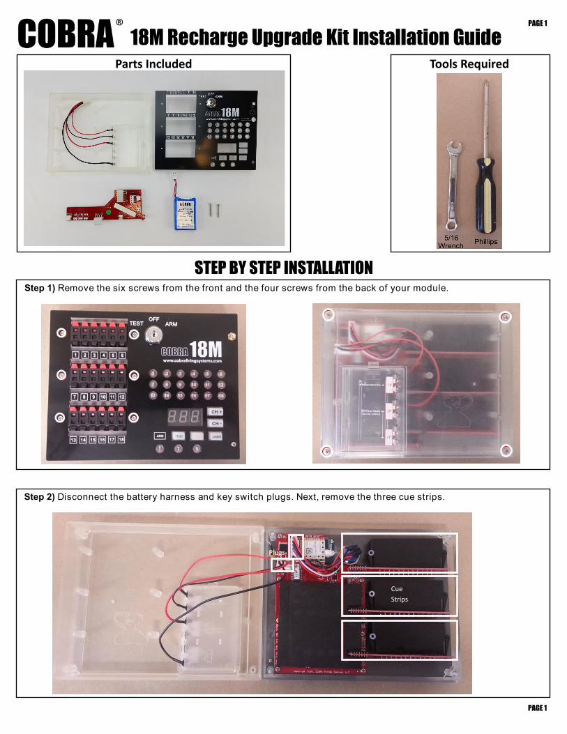
18M Recharge Upgrade Kit Installation Guide
Step 2) Disconnect the battery harness and key switch plugs. Next, remove the three cue strips.
Cue
Strips
Plugs
Step 1) Remove the six screws from the front and the four screws from the back of your module.
Parts Included
Tools Required
STEP BY STEP INSTALLATION
PAGE 1
PAGE 1
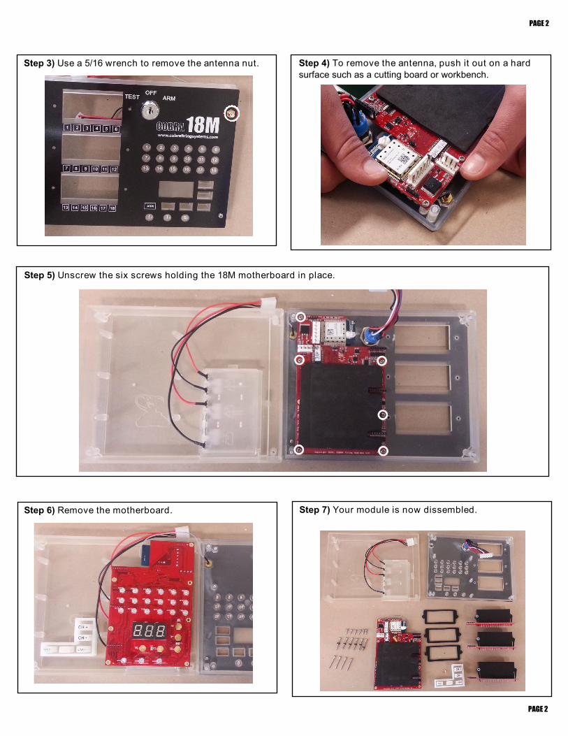
Step 5) Unscrew the six screws holding the 18M motherboard in place.
Step 7) Your module is now dissembled.
PAGE 2
PAGE 2
Step 6) Remove the motherboard.
Step 4) To remove the antenna, push it out on a hard
surface such as a cutting board or workbench.
Step 3) Use a 5/16 wrench to remove the antenna nut.
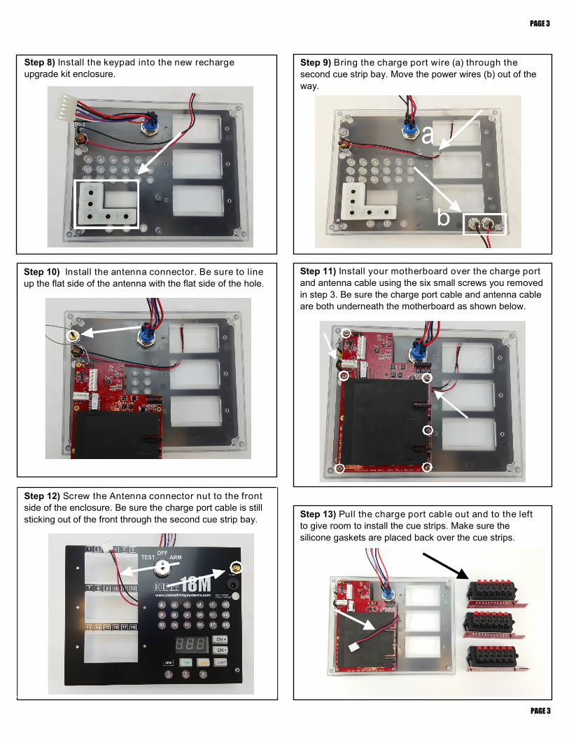
Step 8) Install the keypad into the new recharge
upgrade kit enclosure.
Step 9) Bring the charge port wire (a) through the
second cue strip bay. Move the power wires (b) out of the
way.
Step 10) Install the antenna connector. Be sure to line
up the flat side of the antenna with the flat side of the hole.
Step 12) Screw the Antenna connector nut to the front
side of the enclosure. Be sure the charge port cable is still
sticking out of the front through the second cue strip bay.
Step 11) Install your motherboard over the charge port
and antenna cable using the six small screws you removed
in step 3. Be sure the charge port cable and antenna cable
are both underneath the motherboard as shown below.
Step 13) Pull the charge port cable out and to the left
to give room to install the cue strips. Make sure the
silicone gaskets are placed back over the cue strips.
PAGE 3
PAGE 3
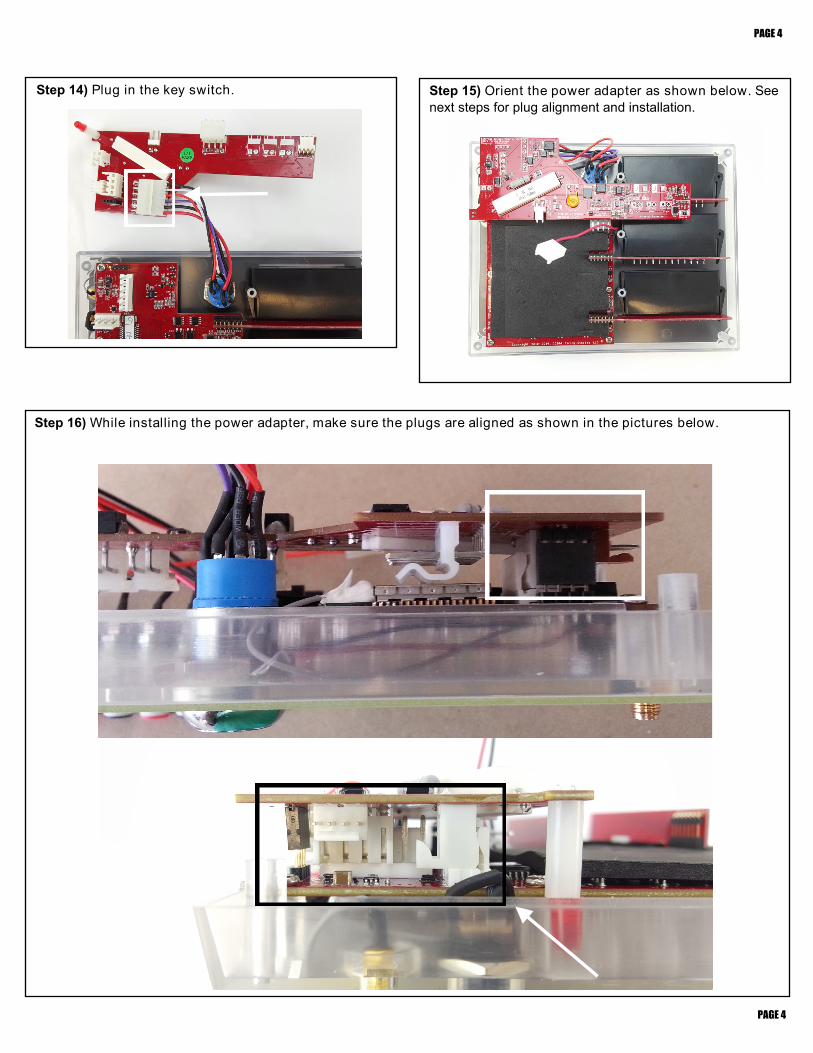
Step 16) While installing the power adapter, make sure the plugs are aligned as shown in the pictures below.
PAGE 4
PAGE 4
Step 14) Plug in the key switch. Step 15) Orient the power adapter as shown below. See
next steps for plug alignment and installation.
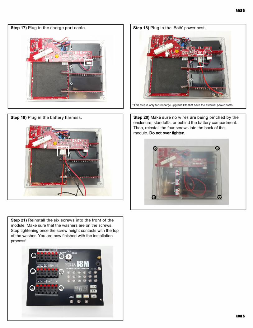
Step 17) Plug in the charge port cable.
Step 18) Plug in the ‘Both’ power post.
Step 19) Plug in the battery harness.
Step 20) Make sure no wires are being pinched by the
enclosure, standoffs, or behind the battery compartment.
Then, reinstall the four screws into the back of the
module. Do not over tighten.
PAGE 5
PAGE 5
Step 21) Reinstall the six screws into the front of the
module. Make sure that the washers are on the screws.
Stop tightening once the screw height contacts with the top
of the washer. You are now finished with the installation
process!
*This step is only for recharge upgrade kits that have the external power posts.

1
18M Power Adapter Calibration Instructions The purpose of this document is to provide instructions on how to calibrate your 18M with a newly installed power adapter. This is required for the module to display correct battery levels both on startup, and when sending low level battery warnings to the 18R and 18R2 remote. If you have already received an 18M with power adapter installed by COBRA, you do not need to perform this process as this has already been done by the COBRA team for you!
It’s a little tricky, but if you follow each step, onebyone, you’ll be a reprogramming wizard by the end of the document! Also, if you get stuck, you can contact us at [email protected] or call Scott Smith at 5182227410. We are here to support you. How it works The wireless reprogrammer is a small device that connects to your PC via USB. You can use this device with a software program called Portal to upload the latest COBRA software to both the remote, firing modules, and audio box. The entire process is done wirelessly without opening the system enclosures. Required hardware You will need the following hardware: 1 PC running either XP, Vista or Windows 7 1 COBRA Wireless Reprogrammer
2
Initial Software Setup This step explains how to install Portal, which is used in the reprogramming process. You only need to perform the initial software setup once. If you have installed 3.0.3 firmware to your modules prior to 9/15/2014, please make sure to redownload the firmware below. A new file for calibration has been included in the zip file. This new file will be used in the update steps below. Step 1 Download and install the Portal software by going to http://www.cobrafiringsystems.com/release/ and clicking on Synapse Portal from the Software Versions section on the right. Make sure to install version 3.0.3 or greater. When installing, please note the following:
● When prompted with a series of options with checkboxes, make sure all are selected ● When prompted that the software may not pass a Windows Logo test, click Continue Anyway ● Disconnect the wireless reprogrammer from the PC before installing Portal ● Once installed, no need to launch Portal immediately, this will be done later
Step 2 Connect the SNAP wireless reprogrammer to a USB port on your PC. In the lowerright corner of your PC, you may see the device as recognized and installing. If you don’t see the device install, that is OK. You are done the initial software setup step.
3
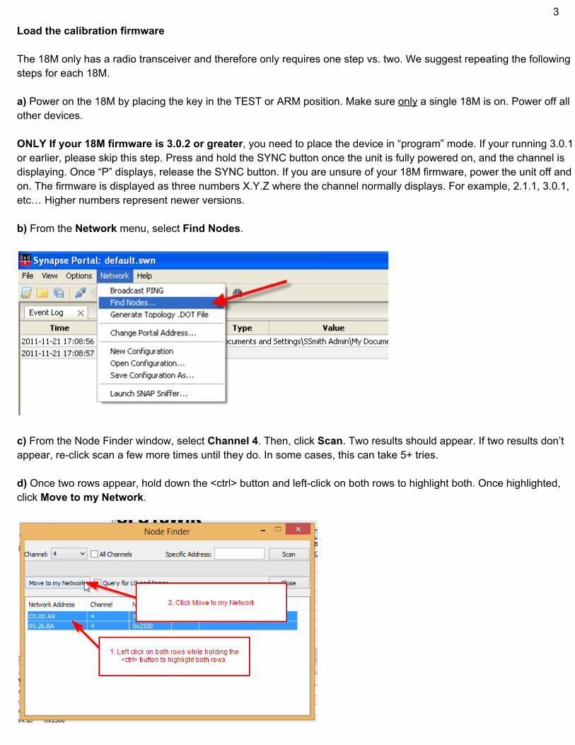
Load the calibration firmware The 18M only has a radio transceiver and therefore only requires one step vs. two. We suggest repeating the following steps for each 18M. a) Power on the 18M by placing the key in the TEST or ARM position. Make sure only a single 18M is on. Power off all other devices. ONLY If your 18M firmware is 3.0.2 or greater, you need to place the device in “program” mode. If your running 3.0.1 or earlier, please skip this step. Press and hold the SYNC button once the unit is fully powered on, and the channel is displaying. Once “P” displays, release the SYNC button. If you are unsure of your 18M firmware, power the unit off and on. The firmware is displayed as three numbers X.Y.Z where the channel normally displays. For example, 2.1.1, 3.0.1, etc… Higher numbers represent newer versions. b) From the Network menu, select Find Nodes.
c) From the Node Finder window, select Channel 4. Then, click Scan. Two results should appear. If two results don’t appear, reclick scan a few more times until they do. In some cases, this can take 5+ tries. d) Once two rows appear, hold down the <ctrl> button and leftclick on both rows to highlight both. Once highlighted, click Move to my Network.
4
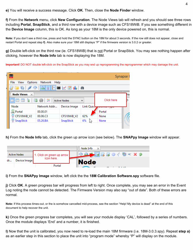
e) You will receive a success message. Click OK. Then, close the Node Finder window. f) From the Network menu, click New Configuration. The Node Views tab will refresh and you should see three rows including Portal, SnapStick, and a third row with a device image such as CFS18WiB. If you see something different in the Device Image column, this is OK. As long as your 18M is the only device powered on, this is normal. Note: If you don’t see a third row, press and hold the SYNC button on the 18M for about 3 seconds. If the row still does not appear, close and restart Portal and repeat step f). Also make sure your 18M still displays “P” if the firmware version is 3.0.2 or greater. g) Double leftclick on the third row (ie. CFS18WiB) that is not Portal or SnapStick. You may see nothing happen after clicking, however the Node Info tab is now displaying the 18M. Important! DO NOT double leftclick on the SnapStick as you may end up reprogramming the reprogrammer which may damage the unit.
h) From the Node Info tab, click the green up arrow icon (see below). The SNAPpy Image window will appear.
i) From the SNAPpy Image window, left click the the 18M Calibration Software.spy software file. j) Click OK. A green progress bar will progress from left to right. Once complete, you may see an error in the Event Log noting the node cannot be detected. The Firmware Version may also say “out of date”. Both of these errors are normal. Note: If this process timesout, or the is somehow cancelled midprocess, see the section “Help! My device is dead” at the end of this document to help recover the unit. k) Once the green progress bar completes, you will see your module display ‘CAL’, followed by a series of numbers. Once the module displays ‘End’ and a number, it is finished. l) Now that the unit is calibrated, you now need to reload the main 18M firmware (i.e. 18M3.0.3.spy). Repeat step a) as an earlier step in this section to place the unit into “program mode” whereby “P” will display on the module.

5
m) Repeat steps fh) as earlier steps in this section. Then, from the SNAPpy Image window, left click the appropriate software file. For example, if you’re upgrading the 18M to 3.0.3, select 18M3.0.3.spy. The naming convention is the device (ie. 18M) followed by a dash and the version number and the .spy file extension. For example, the 18M on 3.0.3 is 18M3.0.3.spy. n) Click OK. A green progress bar will progress from left to right. Once complete, you may see an error in the Event Log noting the node cannot be detected. The Firmware Version may also say “out of date”. Both of these errors are normal. Note: If this process timesout, or the is somehow cancelled midprocess, see the section “Help! My device is dead” at the end of this document to help recover the unit. o) Once finished, the 18M will restart automatically and display the new software version. You are done! Repeat these steps for each 18M with newly installed power adapter.

6
Help! My device is dead. If you have a device that won’t power on due to a timeout or other issue, it’s likely that the firmware was improperly loaded or corrupt. To fix the unit, please follow the following steps. 1) Power on the device even though it looks like it’s dead. Make sure the dead device is the only device that is powered on. 2) Start Portal, connect to the SNAP reprogrammer, and click Network > Find Nodes. 3) Select Channel 4, and click Scan. You should see 2 results. Continue this process until 2 results appear. This may take 5+ times. 4) Click on both results while holding the <ctrl> key. This will highlight both rows. 5) Click Move to my Network. Click OK and close the Finder Node window. 6) Click Network > New Configuration. The node should appear as a third row in the Node Views tab. If it does not, restart Portal, connect to the SNAP reprogrammer, then click Network > New Configuration again. 7) If a third row appears, the Device Image column will likely be blank. Double click this row. The Node Info tab will display this device. 8) From the Node Info tab, click the green up arrow and select the appropriate software file. Click OK. Once the update is complete, the unit should restart. Important! If the dead device was an 18R or 18R2, you need to request a new Net ID from COBRA. Please email [email protected] for further information. If the dead device is an Audio Box or 18M, you don’t need to request a new Net ID.