page : 1 of 70 klm technology - kolmetz.com - home...
TRANSCRIPT
KLM Technology
Group
Practical Engineering Guidelines for Processing
Plant Solutions
www.klmtechgroup.com
Page : 1 of 70
Rev: 04
Rev 1 - April 2007 Rev 2 – Nov 2010 Rev 3 – May 2012 Rev 4 - July 2013
KLM Technology Group #03-12 Block Aronia, Jalan Sri Perkasa 2 Taman Tampoi Utama 81200 Johor Bahru Malaysia
Process Equipment Design Guidelines
Chapter Four
Instrumentation Selection and Sizing
(Engineering Design Guidelines)
Co Author
Rev 01 - A L Ling Rev 02 - Viska Mulyandasari Rev 03 – K Kolmetz Rev 04- Mochamad Adha Firdaus
Karl Kolmetz
KLM Technology Group is providing the introduction to this guideline for free on the internet. Please go to our website to order the complete document.
www.klmtechgroup.com
TABLE OF CONTENT INTRODUCTION
Scope 6
General Instrumentation Consideration 7 Pneumatic Power Supplies 8 Important of Instrumentation Control for Unit Operation 9 Process Variable Measurement Instrument 10 DEFINITIONS 12 NOMENCLATURE 14 THEORY
A) Pressure Measurement 16 Height of a Liquid Column 16
Elastic-Element – Bourdon Tube, Bellows and Diaphragm 18
KLM Technology Group
Practical Engineering
Guidelines for Processing Plant Solutions
Chapter Four
INSTRUMENTATION ( ENGINEERING DESIGN GUIDELINE)
Page 2 of 70
Rev: 04
July 2013
These design guideline are believed to be as accurate as possible, but are very general and not for specific design cases. They were designed for engineers to do preliminary designs and process specification sheets. The final design must always be guaranteed for the service selected by the manufacturing vendor, but these guidelines will greatly reduce the amount of up front engineering hours that are required to develop the final design. The guidelines are a training tool for young engineers or a resource for engineers with experience. This document is entrusted to the recipient personally, but the copyright remains with us. It must not be copied, reproduced or in any way communicated or made accessible to third parties without our written consent.
i) Bourdon Tubes 19
ii) Bellows 20 iii) Diaphragm 22 Electrical Method -Electrical Pressure Transducers 23 i) Strain Gauges 23
B) Level Measurement 24
Gauge Glass 25 Chain or Tape Float Gauges 26
Lever and Shaft Float Gauges (Ball Gauge) 27
Displacer 29
Pressure Gauge 32
Electrical Level Gauges 35
Magnetic Gauge 36
C) Temperature Measurement 37
Thermocouples 37
i) Thermocouples Sensor 40
Resistance Thermometers (RTD) 41 Bimetal Thermometers 42
D) Signal Transmitter 43
E) Recorders and Indicators 44
F) Control System 44
KLM Technology Group
Practical Engineering
Guidelines for Processing Plant Solutions
Chapter Four
INSTRUMENTATION ( ENGINEERING DESIGN GUIDELINE)
Page 3 of 70
Rev: 04
July 2013
These design guideline are believed to be as accurate as possible, but are very general and not for specific design cases. They were designed for engineers to do preliminary designs and process specification sheets. The final design must always be guaranteed for the service selected by the manufacturing vendor, but these guidelines will greatly reduce the amount of up front engineering hours that are required to develop the final design. The guidelines are a training tool for young engineers or a resource for engineers with experience. This document is entrusted to the recipient personally, but the copyright remains with us. It must not be copied, reproduced or in any way communicated or made accessible to third parties without our written consent.
G) Control Modes and Controllers 45
On-off Controller 45
Proportional Controller 46
Proportional Plus Integral (PI) 47
Proportional Plus Derivative Mode (PD) 48
Proportional Plus Integral Plus Derivative (PID) 48
H) Installation, Troubleshooting, and Calibration 52
Failed Systems 52
Poorly Commisioned Systems 53
Poor Performance 54
Calibration 55
Pressure Transmitters 55
Differential pressure transmitters 55
Temperatures transmitters 56
I) Computer Systems 57
Analog Computers 57
Digital Computers 57
i) Microcomputers 57 ii) Minicomputers 58
KLM Technology Group
Practical Engineering
Guidelines for Processing Plant Solutions
Chapter Four
INSTRUMENTATION ( ENGINEERING DESIGN GUIDELINE)
Page 4 of 70
Rev: 04
July 2013
These design guideline are believed to be as accurate as possible, but are very general and not for specific design cases. They were designed for engineers to do preliminary designs and process specification sheets. The final design must always be guaranteed for the service selected by the manufacturing vendor, but these guidelines will greatly reduce the amount of up front engineering hours that are required to develop the final design. The guidelines are a training tool for young engineers or a resource for engineers with experience. This document is entrusted to the recipient personally, but the copyright remains with us. It must not be copied, reproduced or in any way communicated or made accessible to third parties without our written consent.
iii) Process Input / Output Equipment 58
J) Digital First-Level Control Systems 58 Individual Controllers 58 Direct Digital Controllers (DDC) 59 Distributed Control Systems (DCS) 59 Fieldbus 59
K) Analytical Instruments 60 Cyclic Analyzers 60 Continuous Analyzers 60 System Control Diagram 62 L) Fire, Gas and Smoke Detector 62 Flammable Gas Detectors 63 Oil Mist Detectors 64 Very toxic compounds Detectors 64 Fire and Smoke Detectors 64 APPLICATION
Example Case 1: Level Control Schematic Drawing for Fractionation 66 Tower Bottom.
Example Case 2: Pressure Control Schematic Drawing for Fractionation 67 Overhead Drum. Example Case 3: Temperature Control Schematic for Bottom Fractionation 68 Tower
KLM Technology Group
Practical Engineering
Guidelines for Processing Plant Solutions
Chapter Four
INSTRUMENTATION ( ENGINEERING DESIGN GUIDELINE)
Page 5 of 70
Rev: 04
July 2013
These design guideline are believed to be as accurate as possible, but are very general and not for specific design cases. They were designed for engineers to do preliminary designs and process specification sheets. The final design must always be guaranteed for the service selected by the manufacturing vendor, but these guidelines will greatly reduce the amount of up front engineering hours that are required to develop the final design. The guidelines are a training tool for young engineers or a resource for engineers with experience. This document is entrusted to the recipient personally, but the copyright remains with us. It must not be copied, reproduced or in any way communicated or made accessible to third parties without our written consent.
REFEREENCES 69 SPECIFICATION DATA SHEET
Instrument Specification Data Sheet Revision 01 70
LIST OF TABLE Table 1: Properties of Typical Type of Thermocouples. 39
Table 2: Metals Properties for RTDs. 42
Table 3 : Common Measurement Problems 54 Table 4 : Square Root Input / Output Relaionship 56 Table 5 : Continuous Analysis Instruments 61 LIST OF FIGURE Figure 1: Simple Instrument Model 7 Figure 2: U- Shape Tube Manometer 17 Figure 3: Inclined U-Tube Manometer 18 Figure 4: C-spring Bourdon-Tube Pressure Gauge 20 Figure 5: Spring-Loaded Bellows 21 Figure 6: Unopposed Bellows 21 Figure 7: Beam Balance Sensor Bellows 22 Figure 8: Diaphragm Pressure Elements 23
Figure 9: The Wheatstone bridge 24
KLM Technology Group
Practical Engineering
Guidelines for Processing Plant Solutions
Chapter Four
INSTRUMENTATION ( ENGINEERING DESIGN GUIDELINE)
Page 6 of 70
Rev: 04
July 2013
These design guideline are believed to be as accurate as possible, but are very general and not for specific design cases. They were designed for engineers to do preliminary designs and process specification sheets. The final design must always be guaranteed for the service selected by the manufacturing vendor, but these guidelines will greatly reduce the amount of up front engineering hours that are required to develop the final design. The guidelines are a training tool for young engineers or a resource for engineers with experience. This document is entrusted to the recipient personally, but the copyright remains with us. It must not be copied, reproduced or in any way communicated or made accessible to third parties without our written consent.
Figure 10: Reflex Gauge Glass 26 Figure 11: Transparent Gauge Glass 26 Figure 12: Chain and Tape Float Gauge 27
Figure 13: External Ball Float Level Device for Emergency and Alarm Services 28
Figure 14: Internal Ball Float Level Device 29
Figure 15: Displacer Level Measuring Device 30 Figure 16: Quantities of a solid body immersed into a liquid 30 Figure 17: Typical pressure gauge level measurement system 33 Figure 18: HTG Level Measurement System 33 Figure 19: Bubble Tube Level Measurement 34 Figure 20: Conductivity Level Device – Low and High Level Alarm Indication 35
Figure 21: Magnetic Gauge Level Measurement Device 36
Figure 22: Thermal EMF, E, of Commonly Used Thermocouples as a Function of Temperature 38 Figure 23: Typical Thermocouple circuit 39 Figure 24: Industrial Thermocouple Assembly 40
Figure 25: Ceramic Platinum RTD. 41
Figure 26: Flat Strip Bimetal Thermometer 42
Figure 27: Controller Modeling Diagram 46
Figure 28: Response of Step Change in Disturbance with Tuned P, PI, PID, and
Non-controlled. 49
Figure 29 : Typical Chromatograph System 61
KLM Technology Group
Practical Engineering
Guidelines for Processing Plant Solutions
Chapter Four
INSTRUMENTATION ( ENGINEERING DESIGN GUIDELINE)
Page 7 of 70
Rev: 04
July 2013
These design guideline are believed to be as accurate as possible, but are very general and not for specific design cases. They were designed for engineers to do preliminary designs and process specification sheets. The final design must always be guaranteed for the service selected by the manufacturing vendor, but these guidelines will greatly reduce the amount of up front engineering hours that are required to develop the final design. The guidelines are a training tool for young engineers or a resource for engineers with experience. This document is entrusted to the recipient personally, but the copyright remains with us. It must not be copied, reproduced or in any way communicated or made accessible to third parties without our written consent.
KLM Technology Group is providing the introduction to this guideline for free on the internet. Please go to our website to order the complete document.
www.klmtechgroup.com
INTRODUCTION Scope
Instrumentation is a term that is commonly used in engineering, which means measurement and control for industrial process systems. Various processes in petrochemical industries need to be maintained at controlled levels to get the desired product. It is commonly done by controlling such process variables as pressure, temperature, and liquid level by using measurement devices (instruments) with control systems. Control instrumentation plays a significant role in both gathering information from the field and changing the field parameters.
This design guideline covers the selection of measurement devices and control systems which are commonly used in the processing industries. Measurement devices could be classified into various types based on their function.
In this guideline, three types of commonly used measurement devices are explained in detail; such as pressure, level, and temperature measurement devices. Some devices, such as signal transmitter, recorder, and indicator, are generally also networked together to support the measurement device. Those supporting equipments are also explained as well in this guideline.
The selection of measurement device is mostly based on necessity, which variables need to be controlled. But their accuracy, installation cost, and maintenance should be considered as well. Comparing several measurement devices might be important to obtain the most suitable one.
Besides deciding the measurement device to be used in a process, it is also important to put them in a right order. Hence, the control system and control mode explanation are also included in this guideline.
KLM Technology Group
Practical Engineering
Guidelines for Processing Plant Solutions
Chapter Four
INSTRUMENTATION ( ENGINEERING DESIGN GUIDELINE)
Page 8 of 70
Rev: 04
July 2013
These design guideline are believed to be as accurate as possible, but are very general and not for specific design cases. They were designed for engineers to do preliminary designs and process specification sheets. The final design must always be guaranteed for the service selected by the manufacturing vendor, but these guidelines will greatly reduce the amount of up front engineering hours that are required to develop the final design. The guidelines are a training tool for young engineers or a resource for engineers with experience. This document is entrusted to the recipient personally, but the copyright remains with us. It must not be copied, reproduced or in any way communicated or made accessible to third parties without our written consent.
The control system decides how to cope the disturbances in process system by managing behavior of other devices in a system. Generally a controller could be classified into several types based on its characteristics. Each type of controller has their own disadvantages; hence they are commonly combined in industrial process system. No one control system and controller can be utilized for all petrochemical industrial applications. This guideline gives the basic information as a guide to be applied in the process industries.
Some sample calculations based on the real industrial samples are included in this guideline. Calculation spreadsheet for manometer, level measurement using pressure gauge devices and Bimetal thermometers are attached as well and to aid user to understand how to apply the theory for calculations.
KLM Technology Group
Practical Engineering
Guidelines for Processing Plant Solutions
Chapter Four
INSTRUMENTATION ( ENGINEERING DESIGN GUIDELINE)
Page 9 of 70
Rev: 04
July 2013
These design guideline are believed to be as accurate as possible, but are very general and not for specific design cases. They were designed for engineers to do preliminary designs and process specification sheets. The final design must always be guaranteed for the service selected by the manufacturing vendor, but these guidelines will greatly reduce the amount of up front engineering hours that are required to develop the final design. The guidelines are a training tool for young engineers or a resource for engineers with experience. This document is entrusted to the recipient personally, but the copyright remains with us. It must not be copied, reproduced or in any way communicated or made accessible to third parties without our written consent.
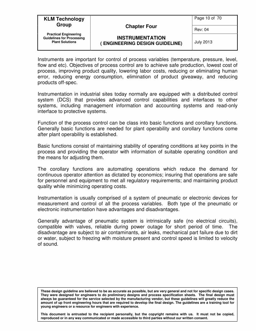
General Concept of Instrumentation An instrument is a device that transforms a physical variable (temperature, length, pressure, velocity, capacity, etc) of interest (the measurand) into a form that is suitable for recording (the measurement). In order for the measurement to have broad and consistent meaning, it is common to employ a standard system of units by which the measurement from one instrument can be compared with the measurement of another. An example of a basic instrument is a ruler. In this case the measurand is the length of some object and the measurement is the number of units (meters, inches, etc.) that represent the length. (4) Simple instrument model (Figure 1), physical measurement variable is measure by measurand as input to sensor; sensor has a function to convert the input to signal variable; signal variables have the property that they can be manipulated in a transmission system, the signal is transmitted to a display or recording device where the measurement can be read by a human observer.
Figure 1: Simple Instrument Model
Measurand
Sensor
Display
Signal Variable
Physical Measurement Variable
Measurement
KLM Technology Group
Practical Engineering
Guidelines for Processing Plant Solutions
Chapter Four
INSTRUMENTATION ( ENGINEERING DESIGN GUIDELINE)
Page 10 of 70
Rev: 04
July 2013
These design guideline are believed to be as accurate as possible, but are very general and not for specific design cases. They were designed for engineers to do preliminary designs and process specification sheets. The final design must always be guaranteed for the service selected by the manufacturing vendor, but these guidelines will greatly reduce the amount of up front engineering hours that are required to develop the final design. The guidelines are a training tool for young engineers or a resource for engineers with experience. This document is entrusted to the recipient personally, but the copyright remains with us. It must not be copied, reproduced or in any way communicated or made accessible to third parties without our written consent.
Instruments are important for control of process variables (temperature, pressure, level, flow and etc). Objectives of process control are to achieve safe production, lowest cost of process, improving product quality, lowering labor costs, reducing or eliminating human error, reducing energy consumption, elimination of product giveaway, and reducing products off-spec.
Instrumentation in industrial sites today normally are equipped with a distributed control system (DCS) that provides advanced control capabilities and interfaces to other systems, including management information and accounting systems and read-only interface to protective systems. Function of the process control can be class into basic functions and corollary functions. Generally basic functions are needed for plant operability and corollary functions come after plant operability is established. Basic functions consist of maintaining stability of operating conditions at key points in the process and providing the operator with information of suitable operating condition and the means for adjusting them. The corollary functions are automating operations which reduce the demand for continuous operator attention as dictated by economics; insuring that operations are safe for personnel and equipment to met all regulatory requirements; and maintaining product quality while minimizing operating costs. Instrumentation is usually comprised of a system of pneumatic or electronic devices for measurement and control of all the process variables. Both type of the pneumatic or electronic instrumentation have advantages and disadvantages. Generally advantage of pneumatic system is intrinsically safe (no electrical circuits), compatible with valves, reliable during power outage for short period of time. The disadvantage are subject to air contaminants, air leaks, mechanical part failure due to dirt or water, subject to freezing with moisture present and control speed is limited to velocity of sound.
KLM Technology Group
Practical Engineering
Guidelines for Processing Plant Solutions
Chapter Four
INSTRUMENTATION ( ENGINEERING DESIGN GUIDELINE)
Page 11 of 70
Rev: 04
July 2013
These design guideline are believed to be as accurate as possible, but are very general and not for specific design cases. They were designed for engineers to do preliminary designs and process specification sheets. The final design must always be guaranteed for the service selected by the manufacturing vendor, but these guidelines will greatly reduce the amount of up front engineering hours that are required to develop the final design. The guidelines are a training tool for young engineers or a resource for engineers with experience. This document is entrusted to the recipient personally, but the copyright remains with us. It must not be copied, reproduced or in any way communicated or made accessible to third parties without our written consent.
Advantages of electronic systems are greater accuracy, more compatible with computer, fast signal transit time, no signal integrity loss if current loop is used. The disadvantages are contacts subject to corrosion, must be air purged, explosion proof, or intrinsically safe to be used in hazardous areas, subject to electrical interference, and more difficult to provide for positive fail-safe operation. Pneumatic Power Supplies Usually known also know as instrument air system, main consideration of the system are
i) Adequate Capacity of the air supply to all instruments in the system. Normally the capacity should maintain at sum of the individual requirements of each instrument in the system plus supplemental volume for purges, leaks, additions and etc. It estimated consumption volume of volume of 3.7 US gallons per minute for each air-consuming device is usually adequate. The air storage tank should have sufficient capacity to maintain that flow rate for five minutes or more as is considered adequate to perform an emergency shut-down of plant.
ii) Filtering is requiring for instrument air since the contamination such as oil,
water, and any hazardous or corrosive gases is not allowed. Non-lubricated compressors should be used if possible, because present of oil in compressors system may cause air contamination and may create a combustible mixture. After the compressing process instrument air will be cooled to remove the contained water. A drying system must be installed to maintain the water dew point at least 6oC below the ambient temperature at line pressure. An after filter is required to remove particulate carryover from the dehydrators.
iii) Safety Regulation is practiced since the instrument air system is designed for
high pressure (up to 59.5 psig) this means relief valve should be installed to protect the system.
iv) The air distribution system should be free of any “pocket” which liquid could
accumulate. If the “pocket” could not be eliminated drain valve should be installed.
KLM Technology Group
Practical Engineering
Guidelines for Processing Plant Solutions
Chapter Four
INSTRUMENTATION ( ENGINEERING DESIGN GUIDELINE)
Page 12 of 70
Rev: 04
July 2013
These design guideline are believed to be as accurate as possible, but are very general and not for specific design cases. They were designed for engineers to do preliminary designs and process specification sheets. The final design must always be guaranteed for the service selected by the manufacturing vendor, but these guidelines will greatly reduce the amount of up front engineering hours that are required to develop the final design. The guidelines are a training tool for young engineers or a resource for engineers with experience. This document is entrusted to the recipient personally, but the copyright remains with us. It must not be copied, reproduced or in any way communicated or made accessible to third parties without our written consent.
Important of Instrumentation Control for Unit Operation
When establishing a control system for a unit operation (reactor, fractionators, and fired heaters), it is very important to ensure that control of each equipment item and circuit provides the ability to maintain material balance, maintain heat balance and allow the control of product quality to the necessary degree.
Material balance control is to prevent build-up or depletion of material for continuous processes. Material balance is easily obtained in piping circuits system, since there is no place in which to store material and no storage from which to withdraw it. In the feed circuits as in fractionation tower, material balance is obtained without automatic control. This is because whatever material is pumped into the circuit exits into the tower and the separately pressure-controlled tower acts as a pressure sink for the feed circuit. For situations in which the circuit pressure must be held higher than would be required merely because of pipe friction pressure drop, material balance is maintained through the use of a pressure controller and valve. With this arrangement, pressure is used as a measure of material balance. Controlling the balance of material may be more difficult when variable holdup of material is possible. In these situations, a level measurement monitors buildup or depletion of liquid and is therefore the basis for control of material balance. Buildup or depletion of vapor in a tower is commonly based on pressure measurement, with many possibilities for valve location. Material balance are achieved when the pressure and bottom level are maintained in the tower. Heat balance control is achieved when the temperature in the unit operation is maintained. In contrast to material balance, heat balance in piping circuits can become quite complex. Heat balance in the fractionation tower can be achieved by maintain of bottom temperature in towers with control the heat supply (normally steam flow rate) from a boiler. In this cascade control of heat balance, the success only can be achieve when level in the bottom tower is maintain, that means a material balance is achieved.
KLM Technology Group
Practical Engineering
Guidelines for Processing Plant Solutions
Chapter Four
INSTRUMENTATION ( ENGINEERING DESIGN GUIDELINE)
Page 13 of 70
Rev: 04
July 2013
These design guideline are believed to be as accurate as possible, but are very general and not for specific design cases. They were designed for engineers to do preliminary designs and process specification sheets. The final design must always be guaranteed for the service selected by the manufacturing vendor, but these guidelines will greatly reduce the amount of up front engineering hours that are required to develop the final design. The guidelines are a training tool for young engineers or a resource for engineers with experience. This document is entrusted to the recipient personally, but the copyright remains with us. It must not be copied, reproduced or in any way communicated or made accessible to third parties without our written consent.
By maintaining material and heat balance in the circuits or unit operation, the product quality control can be achieved and maintained. The means of stability of the operating conditions at key points in the process will lead to successful product quality control. The measurement of product quality is made either directly (i.e., continuously with an on-line analyzer) or indirectly (i.e., by means of a correlation). The end point of the overhead liquid product from the tower is an example. This end point may be measured directly with a boiling point device, or it may be inferred from a over head vapor line temperature measurement. The essential point is that when laying out a control system, the basic measurement information and means for making an adjustment must be made available to the operator. Process Variable Measurement Instrument Process variable such as pressure, level, temperature, flow rate and etc, can be measure with the specific measurement instrument and control with specific control valve / control system. Pressure measurement instruments utilized in today’s market can be classified as manometer, Bourdon tubes, Bellows, diaphragm and electrical pressure transducers. Level measurement instruments used in today’s industrial processes can be classified as gauge glass, chain and tape float gauges, lever and shaft float gauges, displacer level measuring device, head-pressure level gauges, electrical type level gauges and magnetic gauge. Temperature measurement instruments can be classified into thermocouples, resistance thermometers (RTD), and bimetallic thermometers.
KLM Technology Group
Practical Engineering
Guidelines for Processing Plant Solutions
Chapter Four
INSTRUMENTATION ( ENGINEERING DESIGN GUIDELINE)
Page 14 of 70
Rev: 04
July 2013
These design guideline are believed to be as accurate as possible, but are very general and not for specific design cases. They were designed for engineers to do preliminary designs and process specification sheets. The final design must always be guaranteed for the service selected by the manufacturing vendor, but these guidelines will greatly reduce the amount of up front engineering hours that are required to develop the final design. The guidelines are a training tool for young engineers or a resource for engineers with experience. This document is entrusted to the recipient personally, but the copyright remains with us. It must not be copied, reproduced or in any way communicated or made accessible to third parties without our written consent.
The flow rate measurement instruments can obtained by referring to “Flow Measurement Selection and Sizing Engineering Design Guideline” and for the Control valve instrumentation can be obtained by referring to “Control Valve Selection and Sizing Engineering Design Guidelines”. Both guidelines have discussed in detail of the respective instrumentation selection and included sizing as well. Each type of the difference process variable measurement instruments have difference design and suitability for differences process. That means the knowledge of the selection process is very important for the suitable measurement instrument for a specific process.
KLM Technology Group
Practical Engineering
Guidelines for Processing Plant Solutions
Chapter Four
INSTRUMENTATION ( ENGINEERING DESIGN GUIDELINE)
Page 15 of 70
Rev: 04
July 2013
These design guideline are believed to be as accurate as possible, but are very general and not for specific design cases. They were designed for engineers to do preliminary designs and process specification sheets. The final design must always be guaranteed for the service selected by the manufacturing vendor, but these guidelines will greatly reduce the amount of up front engineering hours that are required to develop the final design. The guidelines are a training tool for young engineers or a resource for engineers with experience. This document is entrusted to the recipient personally, but the copyright remains with us. It must not be copied, reproduced or in any way communicated or made accessible to third parties without our written consent.
DEFINITION
Amplifier- A device which draws power from a source other than the input signal and which produces as an output an enlarged reproduction of the essential features of its input.
Adaptive Control - Method of control whereby tuning (response) of the control system is varied with the process condition, unlike other control where tuning is manual and remains constant. Bourdon Tube – It uses a coiled tube which as it expands due to pressure increase causes a rotation of an arm connected to the tube. Capacity - Is the water handling capability of a pump commonly expressed as either gallon per minute (gal/min) or cubic meter per minute (m3/min). Cascade Control – Controllers arranged such that the output of one controller manipulates the set point input of a second controller instead of manipulating a process variable directly. Control Action, Derivatives (Rate)- Control action with the controller output proportional to the rate of change of the input. Control Action Integral (Reset) – Control action with the controller output proportional to the time integral of the error signal. Control Action, Proportional – Control action with the controller output has a linear relationship to the error signal. Controller - A device which receives a measurement of the process variable, compares that measurement with a set point representing the desired control point, and adjusts its output based on the selected control algorithm to minimize the error between the measurement and the set point. If an increase in the measured process variable above the set point causes an increase in the magnitude of the controller output, the controller is said to be “direct acting”. If a process variable increase above the set point causes a decrease in the magnitude of the controller output, the controller is “reverse acting”. Displacer – Is a level measurement devices, displacer density will be greater than the liquid and will act as an immersed body. Operation of the displacer is based on the
KLM Technology Group
Practical Engineering
Guidelines for Processing Plant Solutions
Chapter Four
INSTRUMENTATION ( ENGINEERING DESIGN GUIDELINE)
Page 16 of 70
Rev: 04
July 2013
These design guideline are believed to be as accurate as possible, but are very general and not for specific design cases. They were designed for engineers to do preliminary designs and process specification sheets. The final design must always be guaranteed for the service selected by the manufacturing vendor, but these guidelines will greatly reduce the amount of up front engineering hours that are required to develop the final design. The guidelines are a training tool for young engineers or a resource for engineers with experience. This document is entrusted to the recipient personally, but the copyright remains with us. It must not be copied, reproduced or in any way communicated or made accessible to third parties without our written consent.
measurement of the change in buoyancy of the displacer as the level changes over its length. Distribution Control System (DCS) – Is a system consists of some number of microprocessor-based nodes that are interconnected by a digital communications network, often called a data highway. It is type of computer process control system.
Manometer – Is a device to measure pressures. A common simple manometer consists of a U shaped tube of glass filled with some liquid. Typically the liquid is mercury because of its high density.
PD Controller- A controller with proportional plus derivatives (rate) control action. PI Controller – A controller with proportional plus integral (reset) control action. PID Controller – A controller with proportional plus integral plus derivative control action. RTD (Resistance Temperature Detector) - A resistance temperature detector operates on the principle of the change in electrical resistance in wire as a function of temperature. RTD Element -Sensing portion of the RTD which can be made most commonly of platinum, nickel, or copper. Set Point – The desired value at which a process variable is to be controlled. Transmitter – A device that converts a process measurement variable into an electrical or pneumatic signal suitable for use by an indicating or control system. Thermocouple Thermometer – Is a temperature measuring system comprising a temperature sensing element called a thermocouple which produces an electromotive force (emf), a device for sensing emf which includes a printed scale for converting -emf to equivalent temperature units, and electrical conductors for operatively connecting the two. Thermistor Thermometer - Is a special type of resistor 'comprised of a mixture of metallic oxides known as semiconductors which are substances whose electrical conductivity at or near room temperature is less than that of metals but greater than that of typical insulators, Semiconductors have a high negative temperature coefficient in contrast with most metals which have a positive coefficient.
KLM Technology Group
Practical Engineering
Guidelines for Processing Plant Solutions
Chapter Four
INSTRUMENTATION ( ENGINEERING DESIGN GUIDELINE)
Page 17 of 70
Rev: 04
July 2013
These design guideline are believed to be as accurate as possible, but are very general and not for specific design cases. They were designed for engineers to do preliminary designs and process specification sheets. The final design must always be guaranteed for the service selected by the manufacturing vendor, but these guidelines will greatly reduce the amount of up front engineering hours that are required to develop the final design. The guidelines are a training tool for young engineers or a resource for engineers with experience. This document is entrusted to the recipient personally, but the copyright remains with us. It must not be copied, reproduced or in any way communicated or made accessible to third parties without our written consent.
NOMENCLATURE A Cross section area of body displacer, ft2
b Length of displacer body, ft
C Controlled Variable
c Output bias or Manual reset
d Thickness of flat strip, mm
E Error = PV –SP
FB Buoyant force, Ibm.ft/s2
FG Weight force, Ibm.ft/s2
FR Net force FB –FG, Ibm.ft/s2 f Movement of flat strip, mm g Acceleration of gravity, SI unit or 32.2 ft/s2
∆h Difference height of the liquid level in manometer, SI unit k Specific bending coefficient, 1/oC Ki Integral mode gain constant Kp Proportional gain, (pure number) L Fluid level in tank, ft Ld Dipped length, ft
l Height distance between points of measure P1 and P2 , ft
l Length of flat strip, mm
m Mass of the displacer body immersed in liquid, Ibm P Absolute pressure, SI unit or Hydrostatic pressure at bottom tank, psig P1 Absolute pressure at location 1 in tank, psig P2 Absolute pressure at location 2 in tank, psig P0 Atmospheric pressure, psia Pref Absolute pressure reference, SI unit PB Proportional band in percent, % SP Set – Point Ti Integral mode time constant
∆T Temperature change, o C
Kd Derivative mode gain constant
Td Derivative mode time constant
KLM Technology Group
Practical Engineering
Guidelines for Processing Plant Solutions
Chapter Four
INSTRUMENTATION ( ENGINEERING DESIGN GUIDELINE)
Page 18 of 70
Rev: 04
July 2013
These design guideline are believed to be as accurate as possible, but are very general and not for specific design cases. They were designed for engineers to do preliminary designs and process specification sheets. The final design must always be guaranteed for the service selected by the manufacturing vendor, but these guidelines will greatly reduce the amount of up front engineering hours that are required to develop the final design. The guidelines are a training tool for young engineers or a resource for engineers with experience. This document is entrusted to the recipient personally, but the copyright remains with us. It must not be copied, reproduced or in any way communicated or made accessible to third parties without our written consent.
Greek letters
ρA Density of gas or atmospheric, Ibm/ft3
Bρ Weight density of fluid in manometer, SI unit
ρD Density of the displacer, Ibm/ft3
ρL Density of liquid, Ibm/ft3
θ Angle of column relative the horizontal plane µ Absolute (dynamic) viscosity, cp
υ1 Velocity for upstream, ft/s υ2 Velocity for downstream, ft/s
KLM Technology Group
Practical Engineering
Guidelines for Processing Plant Solutions
Chapter Four
INSTRUMENTATION ( ENGINEERING DESIGN GUIDELINE)
Page 19 of 70
Rev: 04
July 2013
These design guideline are believed to be as accurate as possible, but are very general and not for specific design cases. They were designed for engineers to do preliminary designs and process specification sheets. The final design must always be guaranteed for the service selected by the manufacturing vendor, but these guidelines will greatly reduce the amount of up front engineering hours that are required to develop the final design. The guidelines are a training tool for young engineers or a resource for engineers with experience. This document is entrusted to the recipient personally, but the copyright remains with us. It must not be copied, reproduced or in any way communicated or made accessible to third parties without our written consent.
THEORY
A) Pressure Measurement Pressure defined as force per unit area exerted by a fluid (liquid or gas) on any surface. Usually is expressed in terms of units of weight-force and area (Ib/ft2) or the height of a column of liquid (ft) that produces a like pressure at its base. Absolute pressure (Pabsolute) is the pressure difference between the point of measurement and a perfect vacuum where pressure is zero (Pabsolute = Pgauge + Patm). Gauge pressure (Pgauge) is the pressure difference between the point of measurement and the ambient. In reality, the atmospheric pressure (Patm) can vary, but only the pressure difference is of interest in gauge pressure measurements. The most direct way of measuring pressure is to isolate an area on an elastic mechanical element for the force to act on. The deformation of the sensing element produces displacements and strains that can be precisely sensed to give a calibrated measurement of the pressure. This is the basis method of measurement of pressure for all commercially available pressure sensors today. Process pressure measuring devices may be divided into three groups: (1) based on the measurement of the height of a liquid column, (2) based on the measurement of the distortion of an elastic pressure chamber, and (3) electrical sensing devices. Height of a Liquid Column
Manometers common consists of a U shaped tube of glass filled with some liquid (either water or mercury). Typically the liquid is mercury because of its high density. Manometers measurement methods are based on the measurement of the height of liquid-column, which the pressure being measured is balanced against the pressure exerted by a column of liquid. If the density of the liquid is known, the height of the liquid column is a measure of the pressure. The height of the liquid column may be measured in length units or be calibrated in pressure units. Depending on the pressure range, water and mercury are the liquids most frequently used for manometer. Since the density of the liquid used varies with temperature, the temperature must be taken into account for accurate pressure measurements.
KLM Technology Group
Practical Engineering
Guidelines for Processing Plant Solutions
Chapter Four
INSTRUMENTATION ( ENGINEERING DESIGN GUIDELINE)
Page 20 of 70
Rev: 04
July 2013
These design guideline are believed to be as accurate as possible, but are very general and not for specific design cases. They were designed for engineers to do preliminary designs and process specification sheets. The final design must always be guaranteed for the service selected by the manufacturing vendor, but these guidelines will greatly reduce the amount of up front engineering hours that are required to develop the final design. The guidelines are a training tool for young engineers or a resource for engineers with experience. This document is entrusted to the recipient personally, but the copyright remains with us. It must not be copied, reproduced or in any way communicated or made accessible to third parties without our written consent.
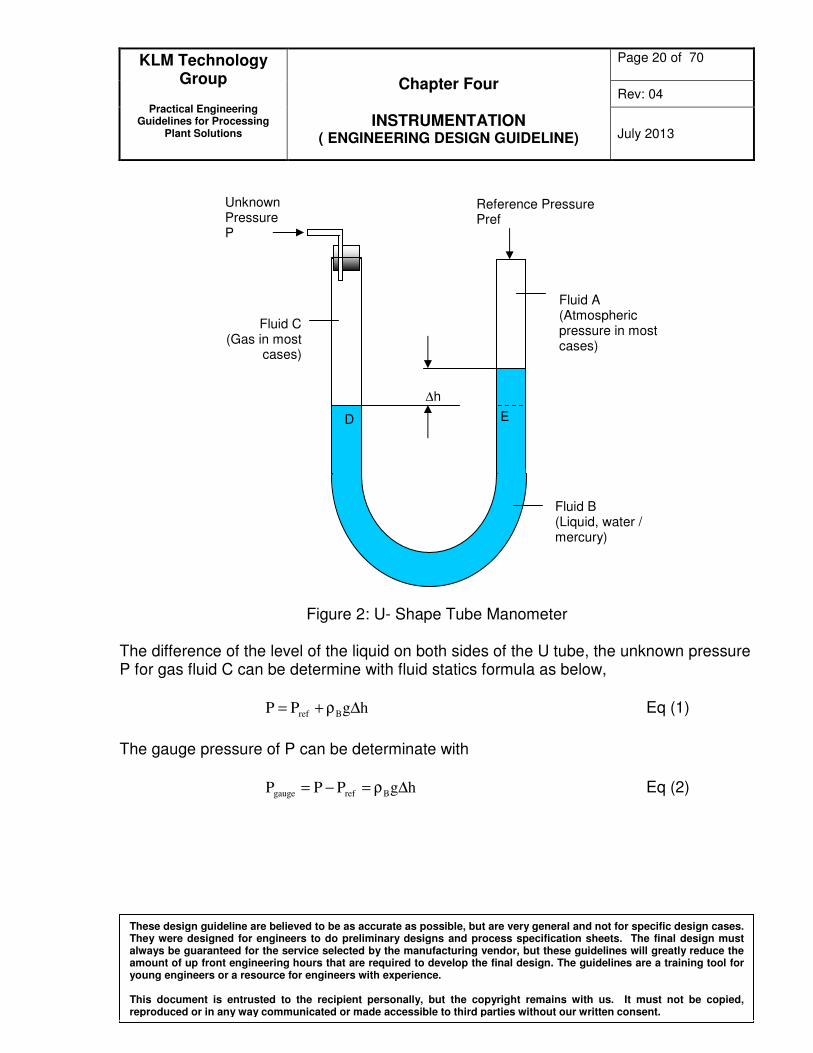
Figure 2: U- Shape Tube Manometer
The difference of the level of the liquid on both sides of the U tube, the unknown pressure P for gas fluid C can be determine with fluid statics formula as below,
hgPP Bref ∆ρ+= Eq (1)
The gauge pressure of P can be determinate with
hgPPP Brefgauge ∆ρ=−= Eq (2)
Reference Pressure Pref
Fluid B (Liquid, water / mercury)
Unknown Pressure P
D E
∆h
Fluid A (Atmospheric pressure in most cases)
Fluid C (Gas in most
cases)
KLM Technology Group
Practical Engineering
Guidelines for Processing Plant Solutions
Chapter Four
INSTRUMENTATION ( ENGINEERING DESIGN GUIDELINE)
Page 21 of 70
Rev: 04
July 2013
These design guideline are believed to be as accurate as possible, but are very general and not for specific design cases. They were designed for engineers to do preliminary designs and process specification sheets. The final design must always be guaranteed for the service selected by the manufacturing vendor, but these guidelines will greatly reduce the amount of up front engineering hours that are required to develop the final design. The guidelines are a training tool for young engineers or a resource for engineers with experience. This document is entrusted to the recipient personally, but the copyright remains with us. It must not be copied, reproduced or in any way communicated or made accessible to third parties without our written consent.
∆h
θ
Fluid B (water or mercury)
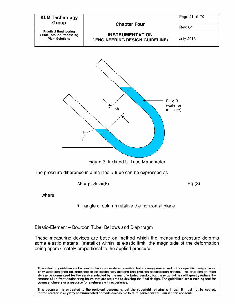
Figure 3: Inclined U-Tube Manometer
The pressure difference in a inclined u-tube can be expressed as
P∆ = )sin(ghB θρ Eq (3)
where
θ = angle of column relative the horizontal plane
Elastic-Element – Bourdon Tube, Bellows and Diaphragm These measuring devices are base on method which the measured pressure deforms some elastic material (metallic) within its elastic limit, the magnitude of the deformation being approximately proportional to the applied pressure.
KLM Technology Group
Practical Engineering
Guidelines for Processing Plant Solutions
Chapter Four
INSTRUMENTATION ( ENGINEERING DESIGN GUIDELINE)
Page 22 of 70
Rev: 04
July 2013
These design guideline are believed to be as accurate as possible, but are very general and not for specific design cases. They were designed for engineers to do preliminary designs and process specification sheets. The final design must always be guaranteed for the service selected by the manufacturing vendor, but these guidelines will greatly reduce the amount of up front engineering hours that are required to develop the final design. The guidelines are a training tool for young engineers or a resource for engineers with experience. This document is entrusted to the recipient personally, but the copyright remains with us. It must not be copied, reproduced or in any way communicated or made accessible to third parties without our written consent.
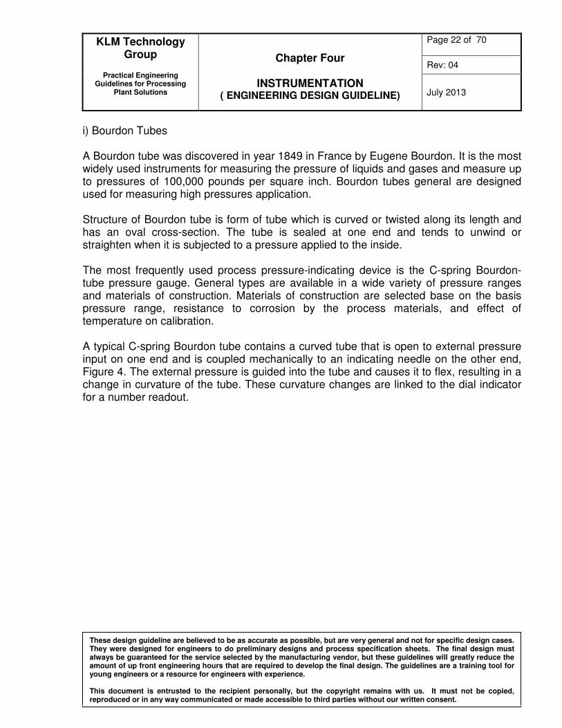
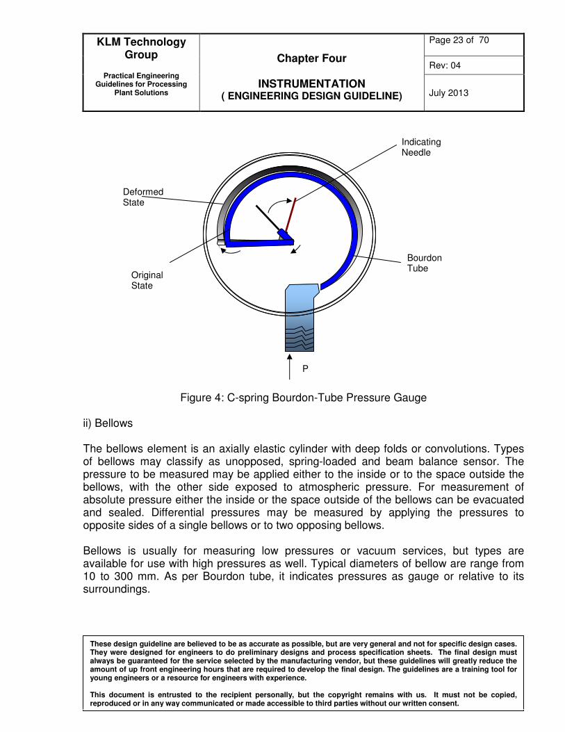
i) Bourdon Tubes A Bourdon tube was discovered in year 1849 in France by Eugene Bourdon. It is the most widely used instruments for measuring the pressure of liquids and gases and measure up to pressures of 100,000 pounds per square inch. Bourdon tubes general are designed used for measuring high pressures application. Structure of Bourdon tube is form of tube which is curved or twisted along its length and has an oval cross-section. The tube is sealed at one end and tends to unwind or straighten when it is subjected to a pressure applied to the inside. The most frequently used process pressure-indicating device is the C-spring Bourdon-tube pressure gauge. General types are available in a wide variety of pressure ranges and materials of construction. Materials of construction are selected base on the basis pressure range, resistance to corrosion by the process materials, and effect of temperature on calibration. A typical C-spring Bourdon tube contains a curved tube that is open to external pressure input on one end and is coupled mechanically to an indicating needle on the other end, Figure 4. The external pressure is guided into the tube and causes it to flex, resulting in a change in curvature of the tube. These curvature changes are linked to the dial indicator for a number readout.
KLM Technology Group
Practical Engineering
Guidelines for Processing Plant Solutions
Chapter Four
INSTRUMENTATION ( ENGINEERING DESIGN GUIDELINE)
Page 23 of 70
Rev: 04
July 2013
These design guideline are believed to be as accurate as possible, but are very general and not for specific design cases. They were designed for engineers to do preliminary designs and process specification sheets. The final design must always be guaranteed for the service selected by the manufacturing vendor, but these guidelines will greatly reduce the amount of up front engineering hours that are required to develop the final design. The guidelines are a training tool for young engineers or a resource for engineers with experience. This document is entrusted to the recipient personally, but the copyright remains with us. It must not be copied, reproduced or in any way communicated or made accessible to third parties without our written consent.
Figure 4: C-spring Bourdon-Tube Pressure Gauge
ii) Bellows The bellows element is an axially elastic cylinder with deep folds or convolutions. Types of bellows may classify as unopposed, spring-loaded and beam balance sensor. The pressure to be measured may be applied either to the inside or to the space outside the bellows, with the other side exposed to atmospheric pressure. For measurement of absolute pressure either the inside or the space outside of the bellows can be evacuated and sealed. Differential pressures may be measured by applying the pressures to opposite sides of a single bellows or to two opposing bellows. Bellows is usually for measuring low pressures or vacuum services, but types are available for use with high pressures as well. Typical diameters of bellow are range from 10 to 300 mm. As per Bourdon tube, it indicates pressures as gauge or relative to its surroundings.
Indicating Needle
Bourdon Tube
Original State
Deformed State
P