practical engineering …kolmetz.com/pdf/egd2/engineering_design_guidelines...klm technology group...
TRANSCRIPT

KLM Technology
Group
Practical Engineering Guidelines for Processing
Plant Solutions
www.klmtechgroup.com
Solutions, Standards and Software
Page : 1 of 94
Rev: 02
Rev 01 March 2015 Rev 02 Nov 2015
KLM Technology Group #03-12 Block Aronia, Jalan Sri Perkasa 2 Taman Tampoi Utama 81200 Johor Bahru Malaysia
Kolmetz Handbook
of Process Equipment Design
PROCESS FLOW SHEET
(ENGINEERING DESIGN GUIDELINE)
Co Author: Rev 01 Aprilia Jaya Rev 02 Riska Ristiyanti
Author / Editor Karl Kolmetz
TABLE OF CONTENT INTRODUCTION 4 Scope 4
General Design Consideration 5
DEFINITIONS 23
KLM Technology Group has developed; 1) Process Engineering Equipment Design Guidelines, 2) Equipment Design Software, 3) Project Engineering Standards and Specifications, and 4) Unit Operations Manuals. Each has many hours of engineering development. KLM is providing the introduction to this guideline for free on the internet. Please go to our website to order the complete document.
www.klmtechgroup.com

KLM Technology Group
Practical Engineering
Guidelines for Processing Plant
Solutions
Kolmetz Handbook of Process Equipment Design
PROCESS FLOW SHEET
(ENGINEERING DESIGN GUIDELINES)
Page 2 of 94
Rev: 02
Nov 2015
These design guideline are believed to be as accurate as possible, but are very general and not for specific design cases. They were designed for engineers to do preliminary designs and process specification sheets. The final design must always be guaranteed for the service selected by the manufacturing vendor, but these guidelines will greatly reduce the amount of up front engineering hours that are required to develop the final design. The guidelines are a training tool for young engineers or a resource for engineers with experience. This document is entrusted to the recipient personally, but the copyright remains with us. It must not be copied, reproduced or in any way communicated or made accessible to third parties without our written consent.
NOMENCLATURE 26 THEORY OF THE DESIGN 27 Kind of Lines and Symbols 28 Instrumentation Design 41 Process Flow Diagram (PFD) 44 Piping and Instrument Diagram (P&ID) 51 A. Guideline for drafting 52
B. Equipment, Instrumentation and Piping Indication 54
C. General Notes 62
D. Establishment of P&IDs Preparation Steps 64
Line Schedule 71 REFEREENCES 68 LIST OF TABLE Table 1: Commercial process simulation programs 19
Table 2. Flowsheet flags of operating conditions in typical units 31
Table 3: Functional symbols for control 42
Table 4: Minimum Information Requirements for Equipment 47
Table 5: Pipeline Symbols 48
Table 6: Equipment symbols 49
Table 7: information of equipment in P&ID 55

KLM Technology Group
Practical Engineering
Guidelines for Processing Plant
Solutions
Kolmetz Handbook of Process Equipment Design
PROCESS FLOW SHEET
(ENGINEERING DESIGN GUIDELINES)
Page 3 of 94
Rev: 02
Nov 2015
These design guideline are believed to be as accurate as possible, but are very general and not for specific design cases. They were designed for engineers to do preliminary designs and process specification sheets. The final design must always be guaranteed for the service selected by the manufacturing vendor, but these guidelines will greatly reduce the amount of up front engineering hours that are required to develop the final design. The guidelines are a training tool for young engineers or a resource for engineers with experience. This document is entrusted to the recipient personally, but the copyright remains with us. It must not be copied, reproduced or in any way communicated or made accessible to third parties without our written consent.
LIST OF FIGURE Figure 1: Block flow diagram of Ammonia Process 7
Figure 2: Pictorial flow diagram establishes key processing steps 8
Figure 3: Process flow diagram of desulfurization 10
Figure 4: Typical P&ID arrangement for three phase separator vessels 14
Figure 5: Piping details isometric diagram 15
Figure 6: Standard type layout for service piping diagram 16
Figure 7: Typical process area plot plan and study elevations 18
Figure 8: Flowsheet: polymer production 19
Figure 9: A typical simulation program 21
Figure 10: Flow chart of steps in simulation 22
Figure 11: Process equipment variables symbols 31
Figure 12: Instrument Symbols 36
Figure 13: Symbol of (a) instrument, (b) cascade control, and
(c) compound control 43
Figure 14: Measuring devices (a) Flow rate measuring and (b) Level
Measuring 44
Figure 15: Symbol of lines and equipments in P&ID 68
Figure 16: Centrifugal pump schedule data sheet 76
Figure 17: Effluent schedule data sheet 77
Figure 18: Line schedule data sheet 78
Figure 19: Another line schedule data sheet 79
Figure 20: Mass balance schedule data sheet 80
Figure 21: Vessel and tank schedule data sheet 81
Figure 22: Tower overhead data sheet 82
KLM Technology Group
Practical Engineering
Guidelines for Processing Plant
Solutions
Kolmetz Handbook of Process Equipment Design
PROCESS FLOW SHEET
(ENGINEERING DESIGN GUIDELINES)
Page 4 of 94
Rev: 02
Nov 2015
These design guideline are believed to be as accurate as possible, but are very general and not for specific design cases. They were designed for engineers to do preliminary designs and process specification sheets. The final design must always be guaranteed for the service selected by the manufacturing vendor, but these guidelines will greatly reduce the amount of up front engineering hours that are required to develop the final design. The guidelines are a training tool for young engineers or a resource for engineers with experience. This document is entrusted to the recipient personally, but the copyright remains with us. It must not be copied, reproduced or in any way communicated or made accessible to third parties without our written consent.
Figure 23: Pipeline data sheet 83
Figure 24: Vessel data sheet 84
Figure 25: Heat exchanger data sheet 85
Figure 26: Relief valve data sheet 86
Figure 27: Control valve data sheet 87
Figure 28: Pump data sheet 88

KLM Technology Group
Practical Engineering
Guidelines for Processing Plant
Solutions
Kolmetz Handbook of Process Equipment Design
PROCESS FLOW SHEET
(ENGINEERING DESIGN GUIDELINES)
Page 5 of 94
Rev: 02
Nov 2015
These design guideline are believed to be as accurate as possible, but are very general and not for specific design cases. They were designed for engineers to do preliminary designs and process specification sheets. The final design must always be guaranteed for the service selected by the manufacturing vendor, but these guidelines will greatly reduce the amount of up front engineering hours that are required to develop the final design. The guidelines are a training tool for young engineers or a resource for engineers with experience. This document is entrusted to the recipient personally, but the copyright remains with us. It must not be copied, reproduced or in any way communicated or made accessible to third parties without our written consent.
KLM Technology Group is providing the introduction to this guideline for free on
the internet. Please go to our website to order the complete document.
www.klmtechgroup.com INTRODUCTION Scope This design guideline covers the basic elements of Process Flow Sheets in sufficient detail to allow an engineer to design a flow sheet with the suitable symbols of equipment, line, indicator and control. The flow sheet is the key document in process design. Flowsheets are intended to represent and explain processes. It shows the arrangement of the equipment selected to carry out the process, the stream connections, stream flow rates and compositions, and the operating conditions. Process flow sheets embody the material and energy balances between and the sizing of the major equipment of the plant. The flow sheet is drawn up from material balances made over the complete process and each individual unit operation. Energy balances are also made to determine the energy flows and the utility requirements. As the process flow sheet is the definitive document on the process, the presentation must be clear, comprehensive, accurate, and complete. The various types of flow sheets are discussed in this guideline. In this section, there are tables that assist in making these flow sheets from the vary reference sources. All the important parameters use in the guideline are explained in the definition section which help the reader more understand the meaning of the parameters or the term used. The theory section explained about kind of lines, equipments, indicator and controller symbols, instrumentation design, process flow diagram, piping and instrument diagram, data sheet examples, engineering ethics, standards and codes. The examples of the data sheets will make the engineer easier to understand.

KLM Technology Group
Practical Engineering
Guidelines for Processing Plant
Solutions
Kolmetz Handbook of Process Equipment Design
PROCESS FLOW SHEET
(ENGINEERING DESIGN GUIDELINES)
Page 6 of 94
Rev: 02
Nov 2015
These design guideline are believed to be as accurate as possible, but are very general and not for specific design cases. They were designed for engineers to do preliminary designs and process specification sheets. The final design must always be guaranteed for the service selected by the manufacturing vendor, but these guidelines will greatly reduce the amount of up front engineering hours that are required to develop the final design. The guidelines are a training tool for young engineers or a resource for engineers with experience. This document is entrusted to the recipient personally, but the copyright remains with us. It must not be copied, reproduced or in any way communicated or made accessible to third parties without our written consent.
General Design Consideration The flowsheet is the key document in process design. It shows the arrangement of the equipment selected to carry out the process, the stream connections, stream flow rates and compositions, and the operating conditions. It is a diagrammatic model of the process. The flowsheet is used by specialist design groups as the basis for their designs. These include piping, instrumentation, and equipment design and plant layout. It is also used by operating personnel for the preparation of operating manuals and operator training. During plant startup and subsequent operation, the flowsheet forms a basis for comparison of operating performance with design. The flowsheet is drawn up from material balances made over the complete process and each individual unit operation. Energy balances are also made to determine the energy flows and the utility requirements. The amount of information shown on a flowsheet will depend on the custom and practice of the particular design office. The following list has therefore been divided into essential items and optional items. The essential items must always be shown; the optional items add to the usefulness of the flowsheet but are not always included Essential Information 1. Stream composition, either
i. the flow rate of each individual component, kg/h, or ii. the stream composition as a weight fraction.
2. Total stream flow rate, kg/h; 3. Stream temperature, 4. Nominal operating pressure (the required operating pressure); 5. Stream enthalpy, kJ/h.
KLM Technology Group
Practical Engineering
Guidelines for Processing Plant
Solutions
Kolmetz Handbook of Process Equipment Design
PROCESS FLOW SHEET
(ENGINEERING DESIGN GUIDELINES)
Page 7 of 94
Rev: 02
Nov 2015
These design guideline are believed to be as accurate as possible, but are very general and not for specific design cases. They were designed for engineers to do preliminary designs and process specification sheets. The final design must always be guaranteed for the service selected by the manufacturing vendor, but these guidelines will greatly reduce the amount of up front engineering hours that are required to develop the final design. The guidelines are a training tool for young engineers or a resource for engineers with experience. This document is entrusted to the recipient personally, but the copyright remains with us. It must not be copied, reproduced or in any way communicated or made accessible to third parties without our written consent.
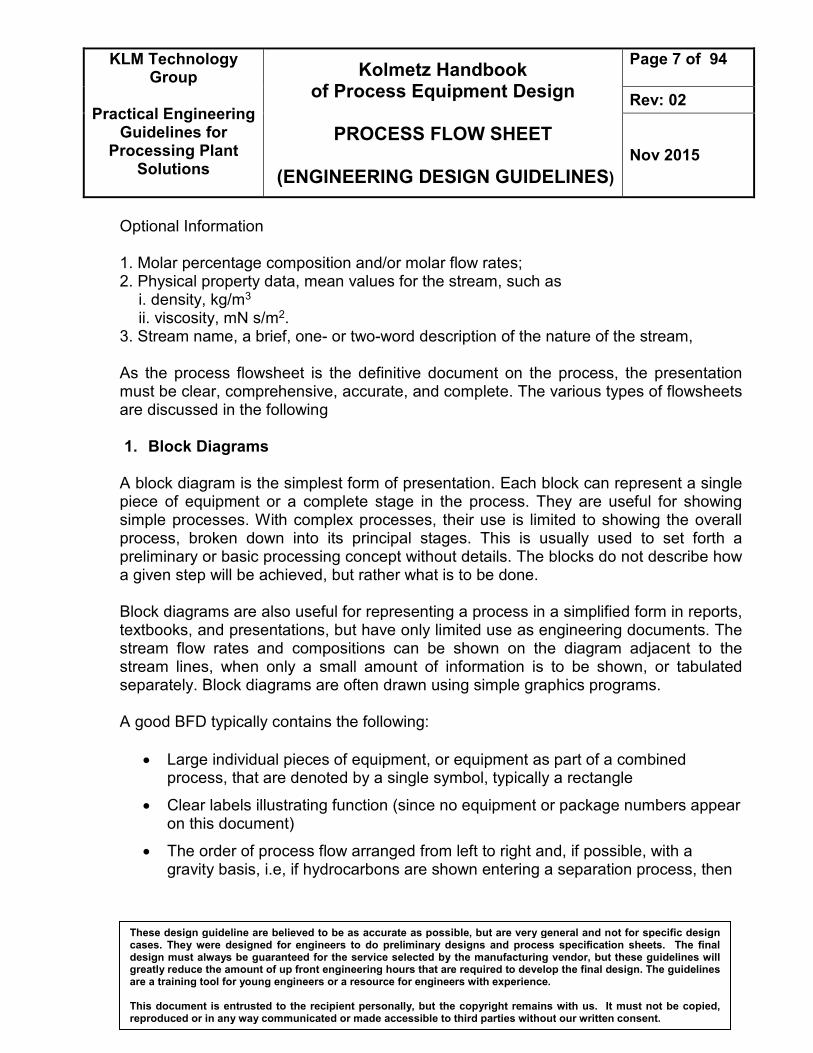
Optional Information 1. Molar percentage composition and/or molar flow rates; 2. Physical property data, mean values for the stream, such as
i. density, kg/m3 ii. viscosity, mN s/m2.
3. Stream name, a brief, one- or two-word description of the nature of the stream, As the process flowsheet is the definitive document on the process, the presentation must be clear, comprehensive, accurate, and complete. The various types of flowsheets are discussed in the following 1. Block Diagrams
A block diagram is the simplest form of presentation. Each block can represent a single piece of equipment or a complete stage in the process. They are useful for showing simple processes. With complex processes, their use is limited to showing the overall process, broken down into its principal stages. This is usually used to set forth a preliminary or basic processing concept without details. The blocks do not describe how a given step will be achieved, but rather what is to be done. Block diagrams are also useful for representing a process in a simplified form in reports, textbooks, and presentations, but have only limited use as engineering documents. The stream flow rates and compositions can be shown on the diagram adjacent to the stream lines, when only a small amount of information is to be shown, or tabulated separately. Block diagrams are often drawn using simple graphics programs. A good BFD typically contains the following:
• Large individual pieces of equipment, or equipment as part of a combined process, that are denoted by a single symbol, typically a rectangle
• Clear labels illustrating function (since no equipment or package numbers appear on this document)
• The order of process flow arranged from left to right and, if possible, with a gravity basis, i.e, if hydrocarbons are shown entering a separation process, then

KLM Technology Group
Practical Engineering
Guidelines for Processing Plant
Solutions
Kolmetz Handbook of Process Equipment Design
PROCESS FLOW SHEET
(ENGINEERING DESIGN GUIDELINES)
Page 8 of 94
Rev: 02
Nov 2015
These design guideline are believed to be as accurate as possible, but are very general and not for specific design cases. They were designed for engineers to do preliminary designs and process specification sheets. The final design must always be guaranteed for the service selected by the manufacturing vendor, but these guidelines will greatly reduce the amount of up front engineering hours that are required to develop the final design. The guidelines are a training tool for young engineers or a resource for engineers with experience. This document is entrusted to the recipient personally, but the copyright remains with us. It must not be copied, reproduced or in any way communicated or made accessible to third parties without our written consent.
gas leaving the process should be shown exiting from the top of the block and condensate from the bottom
• Lines linking equipment or processes to show flow direction
• Wherever more than one line leaves a process, then the processed commodity in each line should be clearly marked
Figure 1: Block flow diagram of Ammonia Process

KLM Technology Group
Practical Engineering
Guidelines for Processing Plant
Solutions
Kolmetz Handbook of Process Equipment Design
PROCESS FLOW SHEET
(ENGINEERING DESIGN GUIDELINES)
Page 9 of 94
Rev: 02
Nov 2015
These design guideline are believed to be as accurate as possible, but are very general and not for specific design cases. They were designed for engineers to do preliminary designs and process specification sheets. The final design must always be guaranteed for the service selected by the manufacturing vendor, but these guidelines will greatly reduce the amount of up front engineering hours that are required to develop the final design. The guidelines are a training tool for young engineers or a resource for engineers with experience. This document is entrusted to the recipient personally, but the copyright remains with us. It must not be copied, reproduced or in any way communicated or made accessible to third parties without our written consent.
2. Pictorial Representation
On the detailed flowsheets used for design and operation, the equipment is normally drawn in a stylized pictorial form. For tender documents or company brochures, actual scale drawings of the equipment are sometimes used, but it is more usual to use a simplified representation. There are several international standards for PFD symbols, but most companies use their own standard symbols, as the cost of converting all of their existing drawings would be excessive. ISO 10628 is the international standard for PFD drawing symbols. 3. Process Flowsheet or Flow Diagram (PFD)
Process flow diagram is a schematic representation of the sequence of all relevant operations occurring during a process and includes information considered desirable for analysis. It can be defined as an operation occurring when an object (or material) is intentionally changed in any of its physical or chemical characteristics, is assembled or disassembled from another object or is arranged or prepared for another operation, transportation, inspection or storage. PFD shows the plant design basis indicating feedstock, product and main streams flow rates and operating conditions. This is used to present the heat balance and material balance of a process. This may be in broad block form with specific key points delineated, or in more detailed form identifying essentially every flow, temperature, and pressure for each basic piece of process equipment or processing step. PFD shows graphically the arrangement of major equipment, process lines and main control loops. This may and usually does include auxiliary services to the process, such as steam, water, air, fuel gas, refrigeration, circulating oil, and so on. This type of sheet is not necessarily distributed to the same groups, because it may contain detailed confidential process data. A typical PFD shows the following items:
• Process piping
• Process flow direction
• Major equipment represented by simplified symbols
• Major bypass and recirculation lines

KLM Technology Group
Practical Engineering
Guidelines for Processing Plant
Solutions
Kolmetz Handbook of Process Equipment Design
PROCESS FLOW SHEET
(ENGINEERING DESIGN GUIDELINES)
Page 10 of 94
Rev: 02
Nov 2015
These design guideline are believed to be as accurate as possible, but are very general and not for specific design cases. They were designed for engineers to do preliminary designs and process specification sheets. The final design must always be guaranteed for the service selected by the manufacturing vendor, but these guidelines will greatly reduce the amount of up front engineering hours that are required to develop the final design. The guidelines are a training tool for young engineers or a resource for engineers with experience. This document is entrusted to the recipient personally, but the copyright remains with us. It must not be copied, reproduced or in any way communicated or made accessible to third parties without our written consent.
• Control and process-critical valves
• Processes identified by system name
• System ratings and operational values
• Compositions of fluids
• Connections between systems.
Figure 3: Process flow diagram of desulfurization

KLM Technology Group
Practical Engineering
Guidelines for Processing Plant
Solutions
Kolmetz Handbook of Process Equipment Design
PROCESS FLOW SHEET
(ENGINEERING DESIGN GUIDELINES)
Page 11 of 94
Rev: 02
Nov 2015
These design guideline are believed to be as accurate as possible, but are very general and not for specific design cases. They were designed for engineers to do preliminary designs and process specification sheets. The final design must always be guaranteed for the service selected by the manufacturing vendor, but these guidelines will greatly reduce the amount of up front engineering hours that are required to develop the final design. The guidelines are a training tool for young engineers or a resource for engineers with experience. This document is entrusted to the recipient personally, but the copyright remains with us. It must not be copied, reproduced or in any way communicated or made accessible to third parties without our written consent.
4. Piping Flowsheet or Mechanical Flow Diagram or Piping and Instrumentation
Diagram (P&ID) The Piping and Instrument Diagram (P&ID), based on the Process Flow Diagram (PFD), represents the technical realization of a process by means of graphical symbols for equipment and piping as well as graphical symbols for process measurement and control functions. This is used to present “mechanical-type” details to piping and mechanical vessel designers, electrical engineers, instrument engineers, and other engineers not directly in need of process details. Piping and Instrument Diagrams are graphical summary of the actual hardware elements in a chemical process plant and their interrelationships of connections to form an operable, safe, and reliable plant. They do not show operating conditions or compositions or flow quantities, but they do show all major as well as minor equipment more realistically than on the process flowsheet. Included are sizes and specification classes of all pipe lines, all valves, and all instruments. The P&IDs include vessels (columns and tanks), pipe sizes, schedule (thickness), materials of construction, all valves (sizes and types), pumps, heat exchangers, reactors, furnaces, compressors, expanders, relief and drain valves, traps, filters, conveyors, hoppers, purchased subsystems, sensors, insulation requirements (thickness and type), controllers (flow, pressure, temperature, level), spares, and other manufactured items, all in a logical configuration. The P&IDs do not include piping lengths and bends. In some engineering systems, detailed specifications cannot be completed until this flowsheet is basically complete. A P&ID carries a wealth of information that spans engineering disciplines to define a process. It is the best way of accurately documenting the operation of a process, and it is truly a coordinating document. P&IDs take the conceptual aspects of the PFD and expand them by adding:
• Detailed symbols
• Detailed equipment information
• Equipment order and process sequence
• Process and utility (non-process) piping
• Process flow direction

KLM Technology Group
Practical Engineering
Guidelines for Processing Plant
Solutions
Kolmetz Handbook of Process Equipment Design
PROCESS FLOW SHEET
(ENGINEERING DESIGN GUIDELINES)
Page 12 of 94
Rev: 02
Nov 2015
These design guideline are believed to be as accurate as possible, but are very general and not for specific design cases. They were designed for engineers to do preliminary designs and process specification sheets. The final design must always be guaranteed for the service selected by the manufacturing vendor, but these guidelines will greatly reduce the amount of up front engineering hours that are required to develop the final design. The guidelines are a training tool for young engineers or a resource for engineers with experience. This document is entrusted to the recipient personally, but the copyright remains with us. It must not be copied, reproduced or in any way communicated or made accessible to third parties without our written consent.
• Major and minor bypass lines
• Line numbers, pipe specifications, and pipe sizes
• Isolation and shutoff valves
• Maintenance vents and drains
• Relief and safety valves
• Instrumentation
• Controls
• Types of process component connections
• Vendor and contractor interfaces
• Skid and package interfaces
• Hydrostatic vents and drains
• Design requirements for hazardous operations. Piping and Instrument Diagrams will be sub-divided between the categories described below. However combination is permissible when a unit is of such a size and design that for example, the utilities and auxiliaries can be shown on one type of diagram with clarity. 1. Process Unit P&ID's P&ID's of a particular unit such as a compressor, and inlet filter scrubber unit are called Process Unit P&ID's. 2. Utility P&ID's P&ID's of utilities such as instrument air and oil system, oily water and waste water, and tempered water are called Utility P&ID's. 3. Distribution P&ID's P&ID's of header distribution systems shown geographically are called Distribution P&ID's. It should be noted that the system need not necessarily be limited to utility distribution and can be used for process distribution.

KLM Technology Group
Practical Engineering
Guidelines for Processing Plant
Solutions
Kolmetz Handbook of Process Equipment Design
PROCESS FLOW SHEET
(ENGINEERING DESIGN GUIDELINES)
Page 13 of 94
Rev: 02
Nov 2015
These design guideline are believed to be as accurate as possible, but are very general and not for specific design cases. They were designed for engineers to do preliminary designs and process specification sheets. The final design must always be guaranteed for the service selected by the manufacturing vendor, but these guidelines will greatly reduce the amount of up front engineering hours that are required to develop the final design. The guidelines are a training tool for young engineers or a resource for engineers with experience. This document is entrusted to the recipient personally, but the copyright remains with us. It must not be copied, reproduced or in any way communicated or made accessible to third parties without our written consent.
The Distribution P&ID shall not duplicate any valves or instrumentation already shown on other P&ID's. The Distribution P&ID for each system shall contain the following information:
• Size, service, line number, whether insulated and type of tracing and Piping Material Specification of headers, sub-headers and lines to individual equipment items.
• Valves at headers (usually for isolation purposes).
• Instruments for header system control.
• Battery limit identification to show proper connection to offsite lines.
• P&ID number and equipment tag number for lines going to Process Unit/Utility P&ID's.
4. Auxiliary P&ID's P&ID's of the equipment piping and instrumentation associated with an item of equipment are called Auxiliary P&ID's. A typical example would be the auxiliary equipment, piping and instrumentation necessary for a large compressor. The intent is to keep the Process Unit P&ID's as uncluttered as possible. The Auxiliary P&ID's shall show auxiliary equipment, utility piping etc. and the following information:
• Piping, instrumentation etc. to be supplied by Vendor.
• Cross references to the vendor's terminal connection designation. 5. Packaged Unit P&ID's P&ID's provided by equipment suppliers for a packaged unit e.g. large centrifugal compressor unit etc. are called Packaged Unit P&ID's. Contractor P&ID's shall indicate the package unit by enclosing the appropriate part of the P&ID concerned with a dash-dot line to show the exact scope of supply. The space enclosed shall state the package unit tag number and the titles of all equipment included with the suppliers name and drawing number. The Vendor P&ID shall be marked up by Contractor to show:
• Package unit tag number
• Tag numbers of all equipment (where allocated) and instruments
• Drawing number allocated by Contractor
KLM Technology Group
Practical Engineering
Guidelines for Processing Plant
Solutions
Kolmetz Handbook of Process Equipment Design
PROCESS FLOW SHEET
(ENGINEERING DESIGN GUIDELINES)
Page 14 of 94
Rev: 02
Nov 2015
These design guideline are believed to be as accurate as possible, but are very general and not for specific design cases. They were designed for engineers to do preliminary designs and process specification sheets. The final design must always be guaranteed for the service selected by the manufacturing vendor, but these guidelines will greatly reduce the amount of up front engineering hours that are required to develop the final design. The guidelines are a training tool for young engineers or a resource for engineers with experience. This document is entrusted to the recipient personally, but the copyright remains with us. It must not be copied, reproduced or in any way communicated or made accessible to third parties without our written consent.
• The letters "Contractor’s name” in brackets shown against any items supplied by Contractor
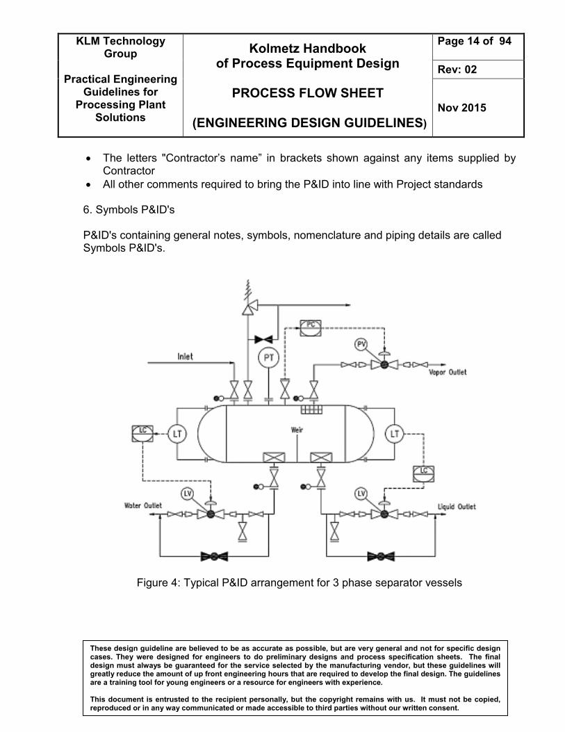
• All other comments required to bring the P&ID into line with Project standards 6. Symbols P&ID's P&ID's containing general notes, symbols, nomenclature and piping details are called Symbols P&ID's.
Figure 4: Typical P&ID arrangement for 3 phase separator vessels

KLM Technology Group
Practical Engineering
Guidelines for Processing Plant
Solutions
Kolmetz Handbook of Process Equipment Design
PROCESS FLOW SHEET
(ENGINEERING DESIGN GUIDELINES)
Page 15 of 94
Rev: 02
Nov 2015
These design guideline are believed to be as accurate as possible, but are very general and not for specific design cases. They were designed for engineers to do preliminary designs and process specification sheets. The final design must always be guaranteed for the service selected by the manufacturing vendor, but these guidelines will greatly reduce the amount of up front engineering hours that are required to develop the final design. The guidelines are a training tool for young engineers or a resource for engineers with experience. This document is entrusted to the recipient personally, but the copyright remains with us. It must not be copied, reproduced or in any way communicated or made accessible to third parties without our written consent.
5. Combined Process and Piping Flowsheet or Diagram
This is used to serve the combined purpose of both the process and the piping flowsheets. This necessarily results in a drawing with considerably more detail than before types. The advantage is in concentrating the complete data and information for a project at one point. It does require close attention in proper reading and often opens data to larger groups of persons who might misinterpret or misuse it. it presents a concise summary of the complete process and key mechanical data for assembly. This type of sheet requires more time for complete preparation, but like all engineering developments preliminary issues are made as information is available. Often the sheet is not complete until the piping and other detailed drawings are finished. This then is an excellent record of the process as well as a worksheet for training operators of the plant.

KLM Technology Group
Practical Engineering
Guidelines for Processing Plant
Solutions
Kolmetz Handbook of Process Equipment Design
PROCESS FLOW SHEET
(ENGINEERING DESIGN GUIDELINES)
Page 16 of 94
Rev: 02
Nov 2015
These design guideline are believed to be as accurate as possible, but are very general and not for specific design cases. They were designed for engineers to do preliminary designs and process specification sheets. The final design must always be guaranteed for the service selected by the manufacturing vendor, but these guidelines will greatly reduce the amount of up front engineering hours that are required to develop the final design. The guidelines are a training tool for young engineers or a resource for engineers with experience. This document is entrusted to the recipient personally, but the copyright remains with us. It must not be copied, reproduced or in any way communicated or made accessible to third parties without our written consent.
Figure 5: Piping details isometric diagram

KLM Technology Group
Practical Engineering
Guidelines for Processing Plant
Solutions
Kolmetz Handbook of Process Equipment Design
PROCESS FLOW SHEET
(ENGINEERING DESIGN GUIDELINES)
Page 17 of 94
Rev: 02
Nov 2015
These design guideline are believed to be as accurate as possible, but are very general and not for specific design cases. They were designed for engineers to do preliminary designs and process specification sheets. The final design must always be guaranteed for the service selected by the manufacturing vendor, but these guidelines will greatly reduce the amount of up front engineering hours that are required to develop the final design. The guidelines are a training tool for young engineers or a resource for engineers with experience. This document is entrusted to the recipient personally, but the copyright remains with us. It must not be copied, reproduced or in any way communicated or made accessible to third parties without our written consent.
6. Utility Flowsheets or Diagrams Utility line diagram (ULD) includes hardware details of the steam, water piping, and control systems. Used to summarize and detail the interrelationship of utilities such as air, water (various types), steam (various types), heat transfer mediums, process vents and purges, safety relief blow-down, and so on to the basic process. The amount of detail is often too great to combine on other sheets, so separate sheets are prepared. These are quite valuable and time saving during the engineering of the project. They also identify the exact flow direction and sequence of tie-in relationships for the operating and maintenance personnel. The distribution of a utility such as steam is by a common distribution pipe, with each unit requiring the utility drawing its supply from that pipe. When a unit has taken its requirement, the utility distribution pipe can then be reduced in size as it continues to the next unit requiring the utility. The order of servicing units is affected by layout, and utility line sizes are affected by the order.

KLM Technology Group
Practical Engineering
Guidelines for Processing Plant
Solutions
Kolmetz Handbook of Process Equipment Design
PROCESS FLOW SHEET
(ENGINEERING DESIGN GUIDELINES)
Page 18 of 94
Rev: 02
Nov 2015
These design guideline are believed to be as accurate as possible, but are very general and not for specific design cases. They were designed for engineers to do preliminary designs and process specification sheets. The final design must always be guaranteed for the service selected by the manufacturing vendor, but these guidelines will greatly reduce the amount of up front engineering hours that are required to develop the final design. The guidelines are a training tool for young engineers or a resource for engineers with experience. This document is entrusted to the recipient personally, but the copyright remains with us. It must not be copied, reproduced or in any way communicated or made accessible to third parties without our written consent.
Figure 6: Standard type layout for service piping diagram

KLM Technology Group
Practical Engineering
Guidelines for Processing Plant
Solutions
Kolmetz Handbook of Process Equipment Design
PROCESS FLOW SHEET
(ENGINEERING DESIGN GUIDELINES)
Page 19 of 94
Rev: 02
Nov 2015
These design guideline are believed to be as accurate as possible, but are very general and not for specific design cases. They were designed for engineers to do preliminary designs and process specification sheets. The final design must always be guaranteed for the service selected by the manufacturing vendor, but these guidelines will greatly reduce the amount of up front engineering hours that are required to develop the final design. The guidelines are a training tool for young engineers or a resource for engineers with experience. This document is entrusted to the recipient personally, but the copyright remains with us. It must not be copied, reproduced or in any way communicated or made accessible to third parties without our written consent.
7. Special Flowsheets or Diagrams From the basic process containing flowsheet, other engineering specialties develop their own details. For example, the instrument engineer often takes the requirements of the process and prepares a completely detailed flowsheet which defines every action of the instruments, control valves, switches, alarm horns, signal lights, and so on. This is his/her detailed working tool. The electrical engineer likewise takes basic process and plant layout requirements and translates them into details for the entire electrical performance of the plant. This will include the electrical requirements of the instrumentation in many cases, but if not, they must be coordinated. 8. Special or Supplemental Aids – Plot Plans
Plot plans are necessary for the proper development of a final and finished process, piping, or utility flowsheet. After broad or overall layout decisions are made, the detailed layout of each processing area is not only helpful but necessary in determining the first realistic estimate of the routing, lengths, and sequence of piping. This is important in such specifications as pipe sizing, and pump head and compressor discharge pressures. The nature of the fluids – whether hazardous, toxic, and so on – as well as the direction or location or availability for entrance to the area, definitely influences decisions regarding the equipment layout on the ground, in the structures, and in relation to buildings. Prevailing wind direction and any other unusual conditions should also be considered.

KLM Technology Group
Practical Engineering
Guidelines for Processing Plant
Solutions
Kolmetz Handbook of Process Equipment Design
PROCESS FLOW SHEET
(ENGINEERING DESIGN GUIDELINES)
Page 20 of 94
Rev: 02
Nov 2015
These design guideline are believed to be as accurate as possible, but are very general and not for specific design cases. They were designed for engineers to do preliminary designs and process specification sheets. The final design must always be guaranteed for the service selected by the manufacturing vendor, but these guidelines will greatly reduce the amount of up front engineering hours that are required to develop the final design. The guidelines are a training tool for young engineers or a resource for engineers with experience. This document is entrusted to the recipient personally, but the copyright remains with us. It must not be copied, reproduced or in any way communicated or made accessible to third parties without our written consent.
Figure 7: Typical process area plot plan and study elevations

KLM Technology Group
Practical Engineering
Guidelines for Processing Plant
Solutions
Kolmetz Handbook of Process Equipment Design
PROCESS FLOW SHEET
(ENGINEERING DESIGN GUIDELINES)
Page 21 of 94
Rev: 02
Nov 2015
These design guideline are believed to be as accurate as possible, but are very general and not for specific design cases. They were designed for engineers to do preliminary designs and process specification sheets. The final design must always be guaranteed for the service selected by the manufacturing vendor, but these guidelines will greatly reduce the amount of up front engineering hours that are required to develop the final design. The guidelines are a training tool for young engineers or a resource for engineers with experience. This document is entrusted to the recipient personally, but the copyright remains with us. It must not be copied, reproduced or in any way communicated or made accessible to third parties without our written consent.
Presentation of Stream Flow Rates The data on the flow rate of each individual component, on the total stream flow rate, and the percentage composition can be shown on the flowsheet in various ways. The simplest method, suitable for simple processes with few pieces of equipment, is to tabulate the data in blocks alongside the process stream lines. The initial layout of the key equipment should be spread farther than looks good to the eye. In fact, it probably looks wasteful of drawing space. Later as process and sometimes service lines, valves, controls, and miscellaneous small accessories are added this “extra” space will be needed to maintain an easily readable sheet. As this develops, attention should be given to the relative weights and styles of lines to aid in the readability of the sheets.
Figure 8: Flowsheet: polymer production

KLM Technology Group
Practical Engineering
Guidelines for Processing Plant
Solutions
Kolmetz Handbook of Process Equipment Design
PROCESS FLOW SHEET
(ENGINEERING DESIGN GUIDELINES)
Page 22 of 94
Rev: 02
Nov 2015
These design guideline are believed to be as accurate as possible, but are very general and not for specific design cases. They were designed for engineers to do preliminary designs and process specification sheets. The final design must always be guaranteed for the service selected by the manufacturing vendor, but these guidelines will greatly reduce the amount of up front engineering hours that are required to develop the final design. The guidelines are a training tool for young engineers or a resource for engineers with experience. This document is entrusted to the recipient personally, but the copyright remains with us. It must not be copied, reproduced or in any way communicated or made accessible to third parties without our written consent.
Process Simulation Programs Most flowsheet calculations are carried out using commercial process simulation programs. The process simulation programs contain models for most unit operations as well as thermodynamic and physical property models. All the commercial programs feature some level of custom modeling capability that allows the designer to add models for nonstandard operations. The principal advantage of simultaneous, dynamic simulators is their ability to model the unsteady-state conditions that occur at startup and during fault conditions. The program consists of 1. A main executive program that controls and keeps track of the flowsheet calculations
and the flow of information to and from the subroutines.
2. A library of equipment performance subroutines (modules) that simulate the equipment and enable the output streams to be calculated from information on the inlet streams.
3. A data bank of physical properties. To a large extent, the utility of a sophisticated flow sheeting program depends on the comprehensiveness of the physical property data bank. The collection of the physical property data required for the design of a particular process and its transformation into a form suitable for a particular flow sheeting program can be very time-consuming.
4. Subroutines for thermodynamics, such as the calculation of vapor-liquid equilibrium and stream enthalpies.
5. Subprograms and data banks for equipment sizing and costing. Process simulation programs enable the designer to consider alternative processing schemes, and the cost routines allow quick economic comparisons to be made. Some programs include optimization routines. To make use of a costing routine, the program must be capable of producing at least approximate equipment designs.
KLM Technology Group
Practical Engineering
Guidelines for Processing Plant
Solutions
Kolmetz Handbook of Process Equipment Design
PROCESS FLOW SHEET
(ENGINEERING DESIGN GUIDELINES)
Page 23 of 94
Rev: 02
Nov 2015
These design guideline are believed to be as accurate as possible, but are very general and not for specific design cases. They were designed for engineers to do preliminary designs and process specification sheets. The final design must always be guaranteed for the service selected by the manufacturing vendor, but these guidelines will greatly reduce the amount of up front engineering hours that are required to develop the final design. The guidelines are a training tool for young engineers or a resource for engineers with experience. This document is entrusted to the recipient personally, but the copyright remains with us. It must not be copied, reproduced or in any way communicated or made accessible to third parties without our written consent.
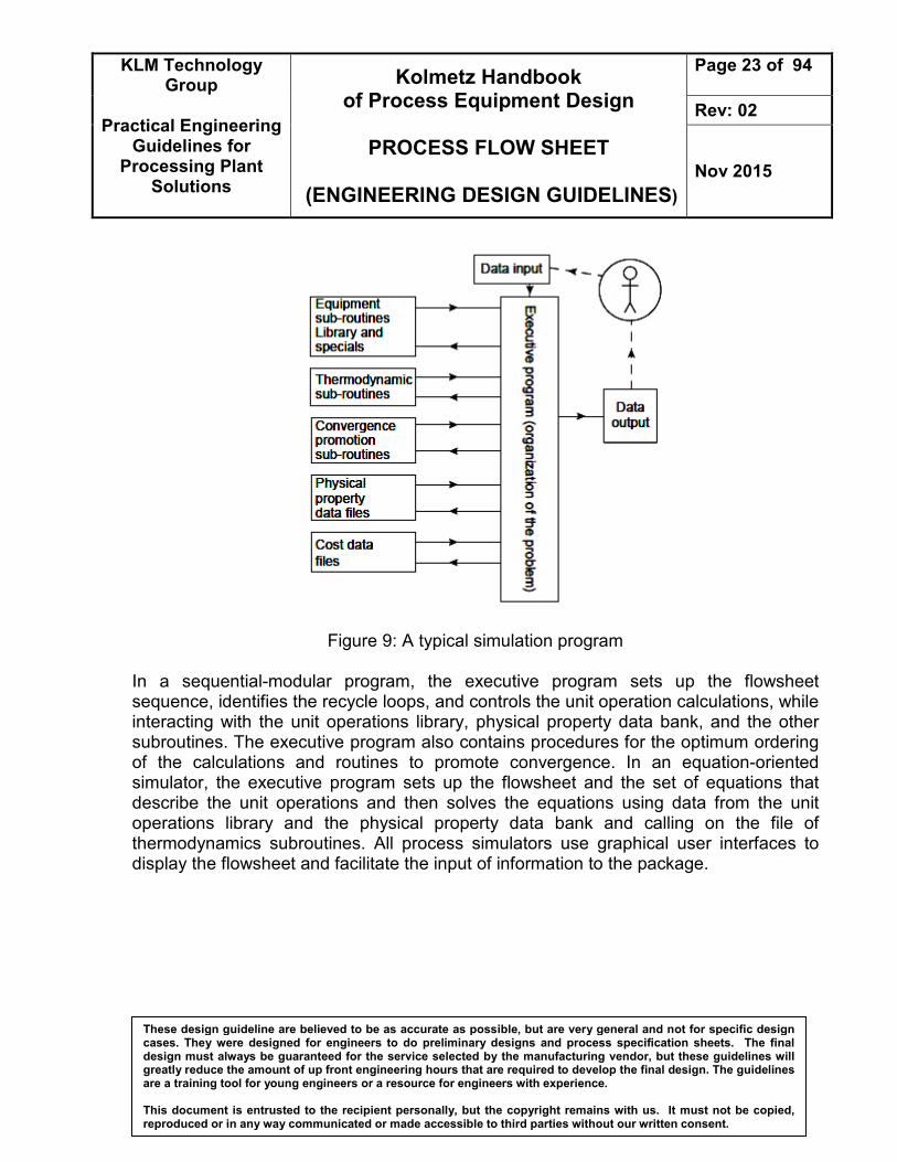
Figure 9: A typical simulation program In a sequential-modular program, the executive program sets up the flowsheet sequence, identifies the recycle loops, and controls the unit operation calculations, while interacting with the unit operations library, physical property data bank, and the other subroutines. The executive program also contains procedures for the optimum ordering of the calculations and routines to promote convergence. In an equation-oriented simulator, the executive program sets up the flowsheet and the set of equations that describe the unit operations and then solves the equations using data from the unit operations library and the physical property data bank and calling on the file of thermodynamics subroutines. All process simulators use graphical user interfaces to display the flowsheet and facilitate the input of information to the package.

KLM Technology Group
Practical Engineering
Guidelines for Processing Plant
Solutions
Kolmetz Handbook of Process Equipment Design
PROCESS FLOW SHEET
(ENGINEERING DESIGN GUIDELINES)
Page 24 of 94
Rev: 02
Nov 2015
These design guideline are believed to be as accurate as possible, but are very general and not for specific design cases. They were designed for engineers to do preliminary designs and process specification sheets. The final design must always be guaranteed for the service selected by the manufacturing vendor, but these guidelines will greatly reduce the amount of up front engineering hours that are required to develop the final design. The guidelines are a training tool for young engineers or a resource for engineers with experience. This document is entrusted to the recipient personally, but the copyright remains with us. It must not be copied, reproduced or in any way communicated or made accessible to third parties without our written consent.
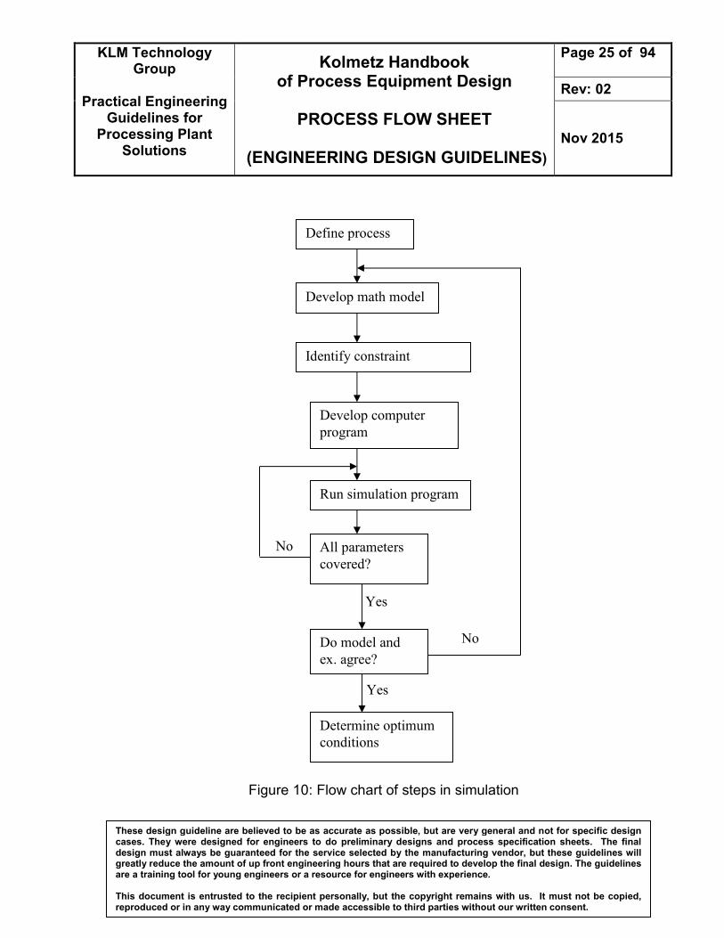
Modeling and simulation procedure
• Translating the description of a physical system into an appropriate mathematical form.
• Selecting a suitable computational technique.
• Implementing the computational technique in the form of a computer program
KLM Technology Group
Practical Engineering
Guidelines for Processing Plant
Solutions
Kolmetz Handbook of Process Equipment Design
PROCESS FLOW SHEET
(ENGINEERING DESIGN GUIDELINES)
Page 25 of 94
Rev: 02
Nov 2015
These design guideline are believed to be as accurate as possible, but are very general and not for specific design cases. They were designed for engineers to do preliminary designs and process specification sheets. The final design must always be guaranteed for the service selected by the manufacturing vendor, but these guidelines will greatly reduce the amount of up front engineering hours that are required to develop the final design. The guidelines are a training tool for young engineers or a resource for engineers with experience. This document is entrusted to the recipient personally, but the copyright remains with us. It must not be copied, reproduced or in any way communicated or made accessible to third parties without our written consent.
Figure 10: Flow chart of steps in simulation
Define process
Develop math model
Identify constraint
Develop computer
program
Run simulation program
All parameters
covered?
Do model and
ex. agree?
Determine optimum
conditions
No
No
Yes
Yes

KLM Technology Group
Practical Engineering
Guidelines for Processing Plant
Solutions
Kolmetz Handbook of Process Equipment Design
PROCESS FLOW SHEET
(ENGINEERING DESIGN GUIDELINES)
Page 26 of 94
Rev: 02
Nov 2015
These design guideline are believed to be as accurate as possible, but are very general and not for specific design cases. They were designed for engineers to do preliminary designs and process specification sheets. The final design must always be guaranteed for the service selected by the manufacturing vendor, but these guidelines will greatly reduce the amount of up front engineering hours that are required to develop the final design. The guidelines are a training tool for young engineers or a resource for engineers with experience. This document is entrusted to the recipient personally, but the copyright remains with us. It must not be copied, reproduced or in any way communicated or made accessible to third parties without our written consent.
DEFINITIONS
Actuators - a type of motor that is responsible for moving or controlling a mechanism or system. It is operated by a source of energy, typically electric current, hydraulic fluid pressure, or pneumatic pressure, and converts that energy into motion.
Cascade control - An automatic control system in which various control units are linked in sequence, each control unit regulating the operation of the next control unit in line Control loops - One segment of a process control system. An open-loop control process requires human intervention, whereas a closed-loop system is entirely automated Control system - a device, or set of devices, that manages, commands, directs or regulates the behavior of other devices or systems. Industrial control systems are used in industrial production for controlling equipment or machines. Distillation - The process of separating materials by successively heating to vaporize a portion and then cooling to liquefy a part of the vapor. Materials to be separated must differ in boiling point and/or relative volatility. Electrical drawings—symbols and diagrams that depict an electrical process. Elevation drawings—a graphical representation that shows the location of process equipment in relation to existing structures and ground level. Equipment location drawings—show the exact floor plan for location of equipment in relation to the plan’s physical boundaries. Evaporators - a device used to turn the liquid form of a chemical into its gaseous form. The liquid is evaporated, or vaporized, into a gas. Field separator - A vessel in the oil or gas field for separating gas, hydrocarbon liquid, and water from each other.

KLM Technology Group
Practical Engineering
Guidelines for Processing Plant
Solutions
Kolmetz Handbook of Process Equipment Design
PROCESS FLOW SHEET
(ENGINEERING DESIGN GUIDELINES)
Page 27 of 94
Rev: 02
Nov 2015
These design guideline are believed to be as accurate as possible, but are very general and not for specific design cases. They were designed for engineers to do preliminary designs and process specification sheets. The final design must always be guaranteed for the service selected by the manufacturing vendor, but these guidelines will greatly reduce the amount of up front engineering hours that are required to develop the final design. The guidelines are a training tool for young engineers or a resource for engineers with experience. This document is entrusted to the recipient personally, but the copyright remains with us. It must not be copied, reproduced or in any way communicated or made accessible to third parties without our written consent.
Flow diagram—a simplified sketch that uses symbols to identify instruments and vessels and to describe the primary flow path through a unit. Flowsheet - a graphic representation, using symbols interconnected with lines, of the successive steps in a procedure or system. Also called flow′ diagram. Foundation drawings—concrete, wire mesh, and steel specifications that identify width, depth, and thickness of footings, support beams, and foundation. Fractionation - Generally used to describe separation of a mixture of hydrocarbons into individual products based on difference in boiling point and/or relative volatility Gas injection - The injection of natural gas into a reservoir to maintain or increase the reservoir pressure or reduce the rate of decline of the reservoir pressure Legends—a document used to define symbols, abbreviations, prefixes, and specialized equipment. Licenser - A company duly organized and existing under the laws of the said company’s country and as referred to in the preamble to the contract. Packaged Unit P&ID's - P&ID's provided by equipment suppliers for a packaged unit e.g. large centrifugal compressor unit etc Pipeline - a line of pipe with pumps, valves, and control devices for conveying liquids, gases, or finely divided solids Piping and Instrument Diagram (P&ID) - a diagram in the process industry which shows the piping of the process flow together with the installed equipment and instrumentation. Plant layout - the most effective physical arrangement, either existing or in plans of industrial facilities i.e. arrangement of machines, processing equipment and service departments to achieve greatest co-ordination and efficiency of 4 M’s (Men, Materials, Machines and Methods) in a plant. Plot Plan- The plot plan is the scaled plan drawing of the processing facility.

KLM Technology Group
Practical Engineering
Guidelines for Processing Plant
Solutions
Kolmetz Handbook of Process Equipment Design
PROCESS FLOW SHEET
(ENGINEERING DESIGN GUIDELINES)
Page 28 of 94
Rev: 02
Nov 2015
These design guideline are believed to be as accurate as possible, but are very general and not for specific design cases. They were designed for engineers to do preliminary designs and process specification sheets. The final design must always be guaranteed for the service selected by the manufacturing vendor, but these guidelines will greatly reduce the amount of up front engineering hours that are required to develop the final design. The guidelines are a training tool for young engineers or a resource for engineers with experience. This document is entrusted to the recipient personally, but the copyright remains with us. It must not be copied, reproduced or in any way communicated or made accessible to third parties without our written consent.
Pneumatic - a section of technology that deals with the study and application of pressurized gas to produce mechanical motion. Pneumatic systems used extensively in industry are commonly powered by compressed air or compressed inert gases.
Process and instrument drawing (P&ID)—a complex diagram that uses process symbols to describe a process unit; also called piping and instrumentation drawing. Process flow diagram - a diagram commonly used in chemical and process engineering to indicate the general flow of plant processes and equipment. The PFD displays the relationship between major equipment of a plant facility and does not show minor details such as piping details and designations. Another commonly used term for a PFD is a flowsheet. Process simulation - a model-based representation of chemical, physical, biological, and other technical processes and unit operations in software. Basic prerequisites are a thorough knowledge of chemical and physical properties of pure components and mixtures, of reactions, and of mathematical models which, in combination, allow the calculation of a process in computers. Project- the equipment, machinery and materials to be procured by the contractor and the works and/or all activities to be performed and rendered by the contractor in accordance with the terms and conditions of the contract documents. Reflux - In fractionation, the portion of condensed overhead returned to the column to enhance achievable purity of the overhead product. Unit- one or all process, offsite and/or utility Units and facilities as applicable to form a complete operable oil, gas and/or petrochemical plant. Valve - a device that regulates, directs or controls the flow of a fluid (gases, liquids, fluidized solids, or slurries) by opening, closing, or partially obstructing various passageways.

KLM Technology Group
Practical Engineering
Guidelines for Processing Plant
Solutions
Kolmetz Handbook of Process Equipment Design
PROCESS FLOW SHEET
(ENGINEERING DESIGN GUIDELINES)
Page 29 of 94
Rev: 02
Nov 2015
These design guideline are believed to be as accurate as possible, but are very general and not for specific design cases. They were designed for engineers to do preliminary designs and process specification sheets. The final design must always be guaranteed for the service selected by the manufacturing vendor, but these guidelines will greatly reduce the amount of up front engineering hours that are required to develop the final design. The guidelines are a training tool for young engineers or a resource for engineers with experience. This document is entrusted to the recipient personally, but the copyright remains with us. It must not be copied, reproduced or in any way communicated or made accessible to third parties without our written consent.
NOMENCLATURE SCFM gas flow rate
ΔP pressure drop
ID internal diameter (in)
OD outer diameter (in)
GPM volume flow rate (gpm)
T temperature (F)
H enthalpy (btu/lb)
P pressure (psig)
PC pressure controller
TC Temperature controller
FC Flow controller
LC level controller