engineering design guidelines mole sieve dehydration...
TRANSCRIPT

KLM Technology
Group
Practical Engineering Guidelines for Processing
Plant Solutions
Solutions, Standards and Software
www.klmtechgroup.com
Page : 1 of 80
Rev: 01
Rev 01 Sept 2015
KLM Technology Group #03-12 Block Aronia, Jalan Sri Perkasa 2 Taman Tampoi Utama 81200 Johor Bahru Malaysia
Kolmetz Handbook
of Process Equipment Design
MOLE SIEVE DEHYDRATION DESIGN AND TROUBLESHOOTING
(ENGINEERING DESIGN GUIDELINE)
Co Author
Rev 01 - Ayu Zaki Lestari
Editor / Author
Karl Kolmetz
TABLE OF CONTENT INTRODUCTION 4
Scope 4 General Design Consideration 4
DEFINITIONS 26 NOMENCLATURE 28 THEORY OF DESIGN 30
KLM Technology Group has developed; 1) Process Engineering Equipment Design Guidelines, 2) Equipment Design Software, 3) Project Engineering Standards and Specifications, and 4) Unit Operations Manuals. Each has many hours of engineering development. KLM is providing the introduction to this guideline for free on the internet. Please go to our website to order the complete document.
www.klmtechgroup.com

KLM Technology Group
Practical Engineering
Guidelines for Processing Plant Solutions
KOLMETZ HANDBOOK OF PROCESS EQUIPMENT DESIGN
MOLE SIEVE DEHYDRATION
DESIGN AND TROUBLESHOOTING
(ENGINEERING DESIGN GUIDELINES)
Page 2 of 80
Rev: 01
Sept 2015
These design guideline are believed to be as accurate as possible, but are very general and not for specific design cases. They were designed for engineers to do preliminary designs and process specification sheets. The final design must always be guaranteed for the service selected by the manufacturing vendor, but these guidelines will greatly reduce the amount of up front engineering hours that are required to develop the final design. The guidelines are a training tool for young engineers or a resource for engineers with experience. This document is entrusted to the recipient personally, but the copyright remains with us. It must not be copied, reproduced or in any way communicated or made accessible to third parties without our written consent.
Adsorption Principles 30 Adsorption Process 36 Desiccant Capacity 43 MTZ Length 45 Adsorber Design 46 Regeneration Design 53 Molecular Sieve Dehydration Unit Design Considerations 57 Operational Problems 60 Savety and Environmental Considerations 66
APPLICATION Example 1: Calculated Size a Molecular Sieve Dehydrator 66 Example 2: Increased Gas Flow and Regenerate Unit Dehydrator 70
REFEREENCES 77 CALCULATION SPREADSHEET 78

KLM Technology Group
Practical Engineering
Guidelines for Processing Plant Solutions
KOLMETZ HANDBOOK OF PROCESS EQUIPMENT DESIGN
MOLE SIEVE DEHYDRATION
DESIGN AND TROUBLESHOOTING
(ENGINEERING DESIGN GUIDELINES)
Page 3 of 80
Rev: 01
Sept 2015
These design guideline are believed to be as accurate as possible, but are very general and not for specific design cases. They were designed for engineers to do preliminary designs and process specification sheets. The final design must always be guaranteed for the service selected by the manufacturing vendor, but these guidelines will greatly reduce the amount of up front engineering hours that are required to develop the final design. The guidelines are a training tool for young engineers or a resource for engineers with experience. This document is entrusted to the recipient personally, but the copyright remains with us. It must not be copied, reproduced or in any way communicated or made accessible to third parties without our written consent.
LIST OF TABLE Table 1: Physical Properties of MEG, DEG, TEG and TREG 6 Table 2: Representative properties of Commercial Silica Gels, Activated Alumina,
and Molecular Sieve 4A 13 Table 3: Most Common Types of Molecular Sieves (Angstrom = 10-10 m) 20 Table 4: Basic Characteristics of Molecular Sieves 22 Table 5: Typical Operating Conditions for Molecular Sieve Dehydration Units 42 Table 6: Dessicant Constant 48
Table 7: Screening Opening for Molecular Sieve 49
LIST OF FIGURE Figure 1: Process flow diagram of glycol dehydration unit 9
Figure 2: Example Solid Desiccant Dehydrator Twin Tower System 15 Figure 3: Molecular Sieve Types A and X Structures 20 Figure 4: Molecular Sieves Selection Chart 24 Figure 5: The Equilibrium Conditions for Water on a Commercial Molecular Sieve 31 Figure 6: Schematic of The adsorption Zones in An adsorber Vessel 33 Figure 7: Vapor-Phase Concentration Profile of an Adsorbate in The Three Zones
of an Adsorption Bed 34
Figure 8: Schematic of a two-bed adsorption unit. Valving is set to have absorber #1 in drying cycle and absorber #2 in regeneration cycle 38

KLM Technology Group
Practical Engineering
Guidelines for Processing Plant Solutions
KOLMETZ HANDBOOK OF PROCESS EQUIPMENT DESIGN
MOLE SIEVE DEHYDRATION
DESIGN AND TROUBLESHOOTING
(ENGINEERING DESIGN GUIDELINES)
Page 4 of 80
Rev: 01
Sept 2015
These design guideline are believed to be as accurate as possible, but are very general and not for specific design cases. They were designed for engineers to do preliminary designs and process specification sheets. The final design must always be guaranteed for the service selected by the manufacturing vendor, but these guidelines will greatly reduce the amount of up front engineering hours that are required to develop the final design. The guidelines are a training tool for young engineers or a resource for engineers with experience. This document is entrusted to the recipient personally, but the copyright remains with us. It must not be copied, reproduced or in any way communicated or made accessible to third parties without our written consent.
Figure 9: Flow Schematic of a Typical Molecular Sieve Dehydration for large Gas Processing Plant 41
Figure 10: Molecular-sieve capacity corection for unsaturated inlet gas 52 Figure 11: Correction for Decrease in Adsorption Capacity Caused by inlet gas
temperature in molecular sieve. 52

KLM Technology Group
Practical Engineering
Guidelines for Processing Plant Solutions
KOLMETZ HANDBOOK OF PROCESS EQUIPMENT DESIGN
MOLE SIEVE DEHYDRATION
DESIGN AND TROUBLESHOOTING
(ENGINEERING DESIGN GUIDELINES)
Page 5 of 80
Rev: 01
Sept 2015
These design guideline are believed to be as accurate as possible, but are very general and not for specific design cases. They were designed for engineers to do preliminary designs and process specification sheets. The final design must always be guaranteed for the service selected by the manufacturing vendor, but these guidelines will greatly reduce the amount of up front engineering hours that are required to develop the final design. The guidelines are a training tool for young engineers or a resource for engineers with experience. This document is entrusted to the recipient personally, but the copyright remains with us. It must not be copied, reproduced or in any way communicated or made accessible to third parties without our written consent.
INTRODUCTION Scope Natural gas may be the most energy efficient fossil fuel, it offers important energy saving benefits when it is used instead of oil or coal. Natural gas may need to be dehydrated because it contains water vapor. This guideline provides knowledge to design a gas dehydration system; especially adsorption treating using molecular sieves. This guideline gives methods to understand basic design of gas dehydration and sizing the molecular sieve dehydrator bed. This guideline will help reader to understand about gas dehydration methods, desiccant selection, bed sizing, regeneration design, operational problem, etc. Additional details of selecting molecular sieve will be presented. The application of the molecular sieve dehydration theory with examples will make the design easier to understand for a molecular sieve dehydration unit. General Design Consideration Natural gas either from natural production or storage reservoirs is saturated with water vapor, which will condense and form gas hydrates if the gas is cooled below its hydrate formation temperature. Gas hydrates are solids that can agglomerate and plug pipelines and equipment, interrupting operations and stopping gas production. This may create an unsafe condition. Water vapor may condense in pipelines, resulting in erosion and corrosion. When accumulated in the pipelines, it might form a liquid plug, reducing the pipeline flow capacity. Natural gas in transit to market should be dehydrated to a controlled water content to avoid these potential problems. Dehydration of natural gas is the removal of the water that is associated with natural gases in vapor form. The natural gas industry has recognized that dehydration is necessary to ensure smooth operation of gas transmission lines. Dehydration prevents the formation of gas hydrates and reduces corrosion. Unless gases are dehydrated, liquid water may condense in pipelines and accumulate at low points along the line, reducing its flow capacity. Water is also removed to meet a water dew point requirement of a sales gas contract specification range from 32.8 to 117 kg/106 std m3. Several methods have been developed to dehydrate gases on an industrial scale.

KLM Technology Group
Practical Engineering
Guidelines for Processing Plant Solutions
KOLMETZ HANDBOOK OF PROCESS EQUIPMENT DESIGN
MOLE SIEVE DEHYDRATION
DESIGN AND TROUBLESHOOTING
(ENGINEERING DESIGN GUIDELINES)
Page 6 of 80
Rev: 01
Sept 2015
These design guideline are believed to be as accurate as possible, but are very general and not for specific design cases. They were designed for engineers to do preliminary designs and process specification sheets. The final design must always be guaranteed for the service selected by the manufacturing vendor, but these guidelines will greatly reduce the amount of up front engineering hours that are required to develop the final design. The guidelines are a training tool for young engineers or a resource for engineers with experience. This document is entrusted to the recipient personally, but the copyright remains with us. It must not be copied, reproduced or in any way communicated or made accessible to third parties without our written consent.
Below is discussed the methods of dehydration Direct Cooling
The saturated water vapor content of natural gas decreases with increased pressure or decreased temperature. Thus, hot gases saturated with water may be partially dehydrated by direct cooling. Gases subjected to compression are normally "after cooled", and this cooling may well remove water from the gas. The cooling process must reduce the temperature to the lowest value that the gas will encounter at the prevailing pressure to prevent further condensation of water. The direct cooling method by expansion or refrigeration, with injection of hydrate inhibitors, is common for less dew point depression in production of pipeline in mild weather regions. Absorption
Absorption dehydration involves the use of a liquid desiccant to remove water vapor from the gas. The most frequently used desiccants in absorption processes are di-ethylene and tri-ethylene glycols. Usually, the absorption/stripping cycle is used for removing large amounts of water, and adsorption is used for cryogenic systems to reach low moisture contents. Although many liquids possess the ability to absorb water from gas, the liquid that is most desirable to use for commercial dehydration purposes should possess the following properties:
1. High absorption efficiency.
2. Easy and economic regeneration.
3. Non-corrosive and non-toxic.
4. No operational problems when used in high concentrations.
5. Minimum absorption of hydrocarbon portion of the gas, and no contamination by acid gases.
Glycols are the most widely used absorption liquids as they approximate the properties that meet the commercial application criteria. Glycol dehydration is the most common dehydration used to meet pipeline sales specification and field requirements. Adsorption processes are used to obtain very low water contents (0.1 ppm or less) required in low

KLM Technology Group
Practical Engineering
Guidelines for Processing Plant Solutions
KOLMETZ HANDBOOK OF PROCESS EQUIPMENT DESIGN
MOLE SIEVE DEHYDRATION
DESIGN AND TROUBLESHOOTING
(ENGINEERING DESIGN GUIDELINES)
Page 7 of 80
Rev: 01
Sept 2015
These design guideline are believed to be as accurate as possible, but are very general and not for specific design cases. They were designed for engineers to do preliminary designs and process specification sheets. The final design must always be guaranteed for the service selected by the manufacturing vendor, but these guidelines will greatly reduce the amount of up front engineering hours that are required to develop the final design. The guidelines are a training tool for young engineers or a resource for engineers with experience. This document is entrusted to the recipient personally, but the copyright remains with us. It must not be copied, reproduced or in any way communicated or made accessible to third parties without our written consent.
temperature processing such as deep NGL extraction and LNG plants. Several glycols have been found suitable for commercial application. 1. Monoethylene glycol is used as hydrate inhibitor where it can be recovered from
gas by separation at below ambient temperatures. It is used in glycol injection exchanger operating at -20 oF to minimize losses.
2. Di-ethylene glycol (DEG) is sometimes used for dehydration for uniformity when
hydrate inhibition is required upstream of dehydration. 3. Tri-ethylene glycol (TEG) is the most commonly used dehydration liquid and is the
assumed glycol type in this process description. 4. Tetra-ethylene glycol (TREG) is more viscous and more expensive than the other
glycols. The only real advantage is its lower vapor pressure which reduces absorber vapor loss. It should only be considered for rare cases where glycol dehydration will be employed on a gas whose temperature exceeds about 50 °C, such as when extreme ambient conditions prevent cooling to a lower temperature.
In process design of the TEG dehydration unit, the upstream unit operation must be considered, as the TEG inlet temperature and water saturation will significantly impact the unit performance. For regions with hot climate, the feed gas should be cooled to the lowest possible temperature with cooling water (or chilled water). This is necessary to ensure that the feed gas temperature meets the TEG unit’s inlet maximum temperature.
Table 1 – Physical Properties of MEG, DEG, TEG and TREG
Glycol MEG DEG TEG TREG
Formula
Molecular mass
Boiling point 101.3 kPa (F)
Freezing point (F)
Density 68 F (lb/ft3)
Viscosity 68 F (mPa.s)
Degradation temperature (F)
HOC2H4OH
62.07
386.6
8.6
69.45
20.9
325.4
HO(C2H4O)2H
106.12
473
17.6
69.64
35.7
323.6
HO(C2H4O)3H
150.17
548.6
19.04
70
47.9
402.8
HO(C2H4O)4H
194.32
620.6
20.84
77.75
60
438.8

KLM Technology Group
Practical Engineering
Guidelines for Processing Plant Solutions
KOLMETZ HANDBOOK OF PROCESS EQUIPMENT DESIGN
MOLE SIEVE DEHYDRATION
DESIGN AND TROUBLESHOOTING
(ENGINEERING DESIGN GUIDELINES)
Page 8 of 80
Rev: 01
Sept 2015
These design guideline are believed to be as accurate as possible, but are very general and not for specific design cases. They were designed for engineers to do preliminary designs and process specification sheets. The final design must always be guaranteed for the service selected by the manufacturing vendor, but these guidelines will greatly reduce the amount of up front engineering hours that are required to develop the final design. The guidelines are a training tool for young engineers or a resource for engineers with experience. This document is entrusted to the recipient personally, but the copyright remains with us. It must not be copied, reproduced or in any way communicated or made accessible to third parties without our written consent.
Liquid desiccant dehydration equipment is simple to operate and maintain. It can easily be automated for unattended operation; for example, glycol dehydration at a remote production well. Liquid desiccants can be used for sour gases, but additional precautions in the design are needed due to the solubility of the acid gases in the desiccant solution. At very high acid gas content and relatively higher pressures the glycols can also be “soluble” in the gas. For the process, the regenerated glycol is fed to the top of an absorber (contactor) where it is contacted with the wet natural gas stream The glycol absorbs water from the natural gas as it flows down through the contactor countercurrent by physical absorption to the gas flow. Water-rich glycol is removed from the bottom of the contactor while the dry natural gas leaves the top of the absorption column and is fed either to a pipeline system or to a gas plant. After leaving the absorber, the water-rich glycol is passes through the reflux condenser coil, flashes off most of the soluble gas in the flash tank (vessel) where hydrocarbon vapors are removed and any liquid hydrocarbons are skimmed from the glycol. This step is necessary as the absorber is typically operated at high pressure and the pressure must be reduced before the regeneration step. Due to the composition of the rich glycol, a vapor phase will form when the pressure is lowered having a high hydrocarbon content. After leaving the flash vessel, the rich glycol is heated in a cross-exchanger and fed to the regenerator. The glycol regenerator consists of a column, an overhead condenser, and a reboiler. In the regenerator, absorbed water is distilled from the glycol at near atmospheric pressure by application of heat. The glycol is thermally regenerated to remove excess water and regain the high glycol purity. The hot lean glycol is cooled by cross-exchange with rich glycol entering the regenerator. It is then fed to a lean pump where its pressure is elevated to that of the glycol absorber. After raising the pressure, the lean solvent is cooled again with a trim cooler before being recirculated into the absorber. This trim cooler can either be a cross-exchanger with the dry gas leaving the absorber. However, there are several operating problems with glycol dehydrators. Suspended foreign matter, such as dirt, scale and iron oxide, may contaminate glycol solutions. Also, overheating of the solutions may produce both low and high boiling decomposition

KLM Technology Group
Practical Engineering
Guidelines for Processing Plant Solutions
KOLMETZ HANDBOOK OF PROCESS EQUIPMENT DESIGN
MOLE SIEVE DEHYDRATION
DESIGN AND TROUBLESHOOTING
(ENGINEERING DESIGN GUIDELINES)
Page 9 of 80
Rev: 01
Sept 2015
These design guideline are believed to be as accurate as possible, but are very general and not for specific design cases. They were designed for engineers to do preliminary designs and process specification sheets. The final design must always be guaranteed for the service selected by the manufacturing vendor, but these guidelines will greatly reduce the amount of up front engineering hours that are required to develop the final design. The guidelines are a training tool for young engineers or a resource for engineers with experience. This document is entrusted to the recipient personally, but the copyright remains with us. It must not be copied, reproduced or in any way communicated or made accessible to third parties without our written consent.
products. The resultant sludge may collect on heating surfaces, causing some loss in efficiency or, in severe cases, complete flow stoppage. Liquids in inlet gas may require installation of an efficient separator ahead of the absorber. Foaming of solution may occur with resultant carry-over of liquid The design of glycol dehydration systems is developed as the project progresses from concept selection, through project specification and detailed design. It is important not to leave decisions to too late a point in the design development. The design shall be consistent with the rest of the plant’s design, for instance: 1. It shall encompass all the anticipated operating conditions and operating scenarios,
including start up from cold. 2. Its sparing, availability, start-up times etc shall be as per the requirements of the
project’s operating and maintenance philosophy and the project’s reliability, availability, maintainability study.
3. Its materials of construction shall be determined by the project’s material selection study.
4. The controls and shutdown functions shall be consistent with those of the rest of the project and subject to the same process controllability reviews, Hazops.
5. Its environmental impact shall be assessed, justified and included in the project’s overall environmental impact.

KLM Technology Group
Practical Engineering
Guidelines for Processing Plant Solutions
KOLMETZ HANDBOOK OF PROCESS EQUIPMENT DESIGN
MOLE SIEVE DEHYDRATION
DESIGN AND TROUBLESHOOTING
(ENGINEERING DESIGN GUIDELINES)
Page 10 of 80
Rev: 01
Sept 2015
These design guideline are believed to be as accurate as possible, but are very general and not for specific design cases. They were designed for engineers to do preliminary designs and process specification sheets. The final design must always be guaranteed for the service selected by the manufacturing vendor, but these guidelines will greatly reduce the amount of up front engineering hours that are required to develop the final design. The guidelines are a training tool for young engineers or a resource for engineers with experience. This document is entrusted to the recipient personally, but the copyright remains with us. It must not be copied, reproduced or in any way communicated or made accessible to third parties without our written consent.
Figure 1: Process flow diagram of glycol dehydration unit
Dry gas
Glycol
contactor
Wet
gas
Free
liquid
Inlet
scrubber
Rich
glycol
Lean
glycol
Surge drum
Filter
Reboiler
Water
vapor Flash gas
Still
Flash
tank

KLM Technology Group
Practical Engineering
Guidelines for Processing Plant Solutions
KOLMETZ HANDBOOK OF PROCESS EQUIPMENT DESIGN
MOLE SIEVE DEHYDRATION
DESIGN AND TROUBLESHOOTING
(ENGINEERING DESIGN GUIDELINES)
Page 11 of 80
Rev: 01
Sept 2015
These design guideline are believed to be as accurate as possible, but are very general and not for specific design cases. They were designed for engineers to do preliminary designs and process specification sheets. The final design must always be guaranteed for the service selected by the manufacturing vendor, but these guidelines will greatly reduce the amount of up front engineering hours that are required to develop the final design. The guidelines are a training tool for young engineers or a resource for engineers with experience. This document is entrusted to the recipient personally, but the copyright remains with us. It must not be copied, reproduced or in any way communicated or made accessible to third parties without our written consent.
The overall design of a glycol system requires components optimization that interacts with each other and also allow for anticipated variations in operating conditions over the life of the plant. The optimization include of glycol circulation rate, dewpoint, temperature pressure, etc. In general, the total circulation rate is determined by the amount of water removal required. The water dewpoint depression, expressed as inlet dewpoint minus outlet dewpoint, is dependent on glycol circulation rate (in gall TEG/lb of water removed), the lean glycol concentration, the number of trays or depth of packing in the contactor and the contact temperature. Adsorption
Adsorption (or solid bed) dehydration is the process where a solid desiccant is used for the removal of water vapor from a gas stream to meet water dew points less than -40 oF. The desiccant material becomes saturated as moisture is adsorbed onto its surface. A good desiccant should therefore have the greatest surface area available for adsorption. The solid desiccants commonly used for gas dehydration are those that can be regenerated and, consequently, used over several adsorption-desorption cycles. The mechanisms of adsorption on a surface are of two types; physical and chemical. The latter process, involving a chemical reaction, is termed "chemisorption", a much stronger chemical bonding occurs between the surface and the adsorbed molecules. Chemical adsorbents find very limited application in gas processing. Adsorbents that allow physical adsorption hold the adsorbate on their surface by surface forces. For physical adsorbents used in gas dehydration, the following properties are desirable.
1. Large surface area for high capacity. Commercial adsorbents have a surface area
of 500-800 m2/g.
2. Good "activity" for the components to be removed and good activity retention with time/use.
3. High mass transfer rate, i.e., a high rate of removal.
4. Easy, economic regeneration.
5. Small resistance to gas flow, so that the pressure drop through the dehydration system is small.

KLM Technology Group
Practical Engineering
Guidelines for Processing Plant Solutions
KOLMETZ HANDBOOK OF PROCESS EQUIPMENT DESIGN
MOLE SIEVE DEHYDRATION
DESIGN AND TROUBLESHOOTING
(ENGINEERING DESIGN GUIDELINES)
Page 12 of 80
Rev: 01
Sept 2015
These design guideline are believed to be as accurate as possible, but are very general and not for specific design cases. They were designed for engineers to do preliminary designs and process specification sheets. The final design must always be guaranteed for the service selected by the manufacturing vendor, but these guidelines will greatly reduce the amount of up front engineering hours that are required to develop the final design. The guidelines are a training tool for young engineers or a resource for engineers with experience. This document is entrusted to the recipient personally, but the copyright remains with us. It must not be copied, reproduced or in any way communicated or made accessible to third parties without our written consent.
6. High mechanical strength to resist crushing and dust formation. The adsorbent also must retain strength when "wet".
7. Cheap, non-corrosive, non-toxic, chemically inert, high bulk density and small volume changes upon adsorption and desorption of water.
Adsorbents used for removing water from a fluid stream are known as "solid desiccant". The characteristics of solid desiccants vary significantly depending on their physical and chemical properties. Many known solids have some ability to adsorb, but relatively few are commercially important. Some of the qualities that make a solid adsorbent commercially important are:
1. Available in large quantity;
2. High adsorption capacity: this reduces the adsorbent volume, requiring smaller vessels, resulting in lower capital and operating costs;
3. High selectivity, this permits removal of only the undesirable components and reduces operating expenses;
4. Easy regeneration: low regeneration temperature reduces the heating requirement for solid desiccant regeneration;
5. Ability to reduce the materials to be adsorbed to a low concentration;
6. Ability to be regenerated and used again;
7. Low-pressure-drop design: this makes more pressure available for the turboexpander operation in an NGL recovery process;
8. Good mechanical integrity: high crush strength, low attrition, low dust formation, and high stability against aging reduces the frequency of adsorbent change-out and downtime-related losses in production;
9. Environment-friendly properties: the materials should be noncorrosive, nontoxic,, and chemically inert to permit safe handling;
10. Chemical inertness;
11. Reasonable adsorbent price.

KLM Technology Group
Practical Engineering
Guidelines for Processing Plant Solutions
KOLMETZ HANDBOOK OF PROCESS EQUIPMENT DESIGN
MOLE SIEVE DEHYDRATION
DESIGN AND TROUBLESHOOTING
(ENGINEERING DESIGN GUIDELINES)
Page 13 of 80
Rev: 01
Sept 2015
These design guideline are believed to be as accurate as possible, but are very general and not for specific design cases. They were designed for engineers to do preliminary designs and process specification sheets. The final design must always be guaranteed for the service selected by the manufacturing vendor, but these guidelines will greatly reduce the amount of up front engineering hours that are required to develop the final design. The guidelines are a training tool for young engineers or a resource for engineers with experience. This document is entrusted to the recipient personally, but the copyright remains with us. It must not be copied, reproduced or in any way communicated or made accessible to third parties without our written consent.
Some materials that satisfy these criteria, in the order of increasing cost are; bauxite; alumina; silica gels and silica-alumina gels; molecular sieves; and carbon. • Bauxite – naturally occuring mineral composed primarily of alumina (Al2O3. x H2O).
• Gels – alumina or silica gels manufactured and conditioned to have an affinity for water. Silica Gel is a generic name for a gel manufactured from sulfuric acid and sodium silicate. It is essentially pure silicon dioxide, SiO2. When used for dehydration, silica gel will give outlet dewpoints of approximately –60°F.
• Alumina – a manufactured or natural occurring form of aluminum oxide that is activated by heating. Alumina is a hydrated form of alumina oxide (Al2O3). It is used for gas and liquid dehydration and will give outlet dewpoints of about –90°F. Less heat is required to regenerate alumina and silica gel than for molecular sieve, and the regeneration temperature is lower.
• Molecular Sieves – manufactured or naturally occurring aluminosilicates exhibiting a degree of selectivity based on crystalline structure in their adsorption of natural gas constituents. Molecular sieves are a class of aluminosilicates. They produce the lowest water dewpoints, and can be used to simultaneously sweeten and dry gases and liquids. Their equilibrium water capacity is much less dependent on adsorption temperature and relative humidity. Dehydration to a –150°F dewpoint is possible with molecular sieves.
• Carbon (charcoal) – a carbon product treated and activated to have adsorptive capacity.
All, except carbon, are used for dehydration. Carbon has desirable properties for hydrocarbon removal and adsorption of certain impurities but possesses negligible water capacity.
KLM Technology Group
Practical Engineering
Guidelines for Processing Plant Solutions
KOLMETZ HANDBOOK OF PROCESS EQUIPMENT DESIGN
MOLE SIEVE DEHYDRATION
DESIGN AND TROUBLESHOOTING
(ENGINEERING DESIGN GUIDELINES)
Page 14 of 80
Rev: 01
Sept 2015
These design guideline are believed to be as accurate as possible, but are very general and not for specific design cases. They were designed for engineers to do preliminary designs and process specification sheets. The final design must always be guaranteed for the service selected by the manufacturing vendor, but these guidelines will greatly reduce the amount of up front engineering hours that are required to develop the final design. The guidelines are a training tool for young engineers or a resource for engineers with experience. This document is entrusted to the recipient personally, but the copyright remains with us. It must not be copied, reproduced or in any way communicated or made accessible to third parties without our written consent.
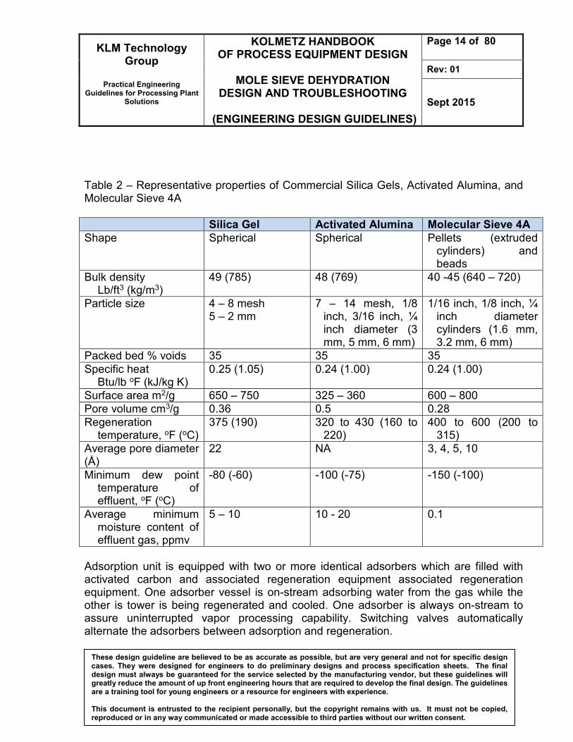
Table 2 – Representative properties of Commercial Silica Gels, Activated Alumina, and Molecular Sieve 4A
Silica Gel Activated Alumina Molecular Sieve 4A
Shape Spherical Spherical Pellets (extruded cylinders) and beads
Bulk density Lb/ft3 (kg/m3)
49 (785) 48 (769) 40 -45 (640 – 720)
Particle size 4 – 8 mesh 5 – 2 mm
7 – 14 mesh, 1/8 inch, 3/16 inch, ¼ inch diameter (3 mm, 5 mm, 6 mm)
1/16 inch, 1/8 inch, ¼ inch diameter cylinders (1.6 mm, 3.2 mm, 6 mm)
Packed bed % voids 35 35 35 Specific heat
Btu/lb oF (kJ/kg K) 0.25 (1.05) 0.24 (1.00) 0.24 (1.00)
Surface area m2/g 650 – 750 325 – 360 600 – 800 Pore volume cm3/g 0.36 0.5 0.28 Regeneration
temperature, oF (oC) 375 (190) 320 to 430 (160 to
220) 400 to 600 (200 to
315) Average pore diameter (Å)
22 NA 3, 4, 5, 10
Minimum dew point temperature of effluent, oF (oC)
-80 (-60) -100 (-75) -150 (-100)
Average minimum moisture content of effluent gas, ppmv
5 – 10 10 - 20 0.1
Adsorption unit is equipped with two or more identical adsorbers which are filled with activated carbon and associated regeneration equipment associated regeneration equipment. One adsorber vessel is on-stream adsorbing water from the gas while the other is tower is being regenerated and cooled. One adsorber is always on-stream to assure uninterrupted vapor processing capability. Switching valves automatically alternate the adsorbers between adsorption and regeneration.

KLM Technology Group
Practical Engineering
Guidelines for Processing Plant Solutions
KOLMETZ HANDBOOK OF PROCESS EQUIPMENT DESIGN
MOLE SIEVE DEHYDRATION
DESIGN AND TROUBLESHOOTING
(ENGINEERING DESIGN GUIDELINES)
Page 15 of 80
Rev: 01
Sept 2015
These design guideline are believed to be as accurate as possible, but are very general and not for specific design cases. They were designed for engineers to do preliminary designs and process specification sheets. The final design must always be guaranteed for the service selected by the manufacturing vendor, but these guidelines will greatly reduce the amount of up front engineering hours that are required to develop the final design. The guidelines are a training tool for young engineers or a resource for engineers with experience. This document is entrusted to the recipient personally, but the copyright remains with us. It must not be copied, reproduced or in any way communicated or made accessible to third parties without our written consent.
Hot gas is used to drive off the adsorbed water from the desiccant, after which the tower is cooled with an unheated gas stream. The towers are switched before the on-stream tower becomes water saturated. In this configuration, part of the dried gas is used for regeneration and cooling, and is recycled to the inlet separator. Other streams may be used if they are dry enough, such as part of the residue gas. To process adsorption of water from the hydrocarbon vapor-air mixture, the mixture first flows up through the on-stream adsorber vessel. In the adsorber vessel, the activated carbon adsorbs the hydrocarbon vapor, thus clean air vents from the bed with minimal hydrocarbon content. The second adsorber is being regenerated off-line. A combination of high vacuum and purge air stripping are used for the carbon bed regeneration to remove previously adsorbed hydrocarbon vapor from the carbon and restore the carbon's ability to adsorb vapor during the next cycle. The liquid ring vacuum pump extracts concentrated hydrocarbon vapor from the carbon bed and discharges it into a three phase separator that separates the vacuum pump seal fluid, the hydrocarbon condensate and the non-condensed hydrocarbon/air vapors. The seal fluid is pumped from the separator through a seal fluid cooler to remove the heat of compression from the seal fluid. Then the seal fluid is returned to the liquid ring pump. Other types of vacuum generators can be substituted for the standard liquid ring pump in chlorinated hydrocarbon vapor recovery to avoid incompatibility of the vapor with the seal fluid required by the liquid ring pump. Furthermore hydrocarbon vapor and condensate flow from the separator to an absorber column section as the final recovery device where it is subsequently recovered by absorption into a liquid hydrocarbon absorbent. The circulating absorbent supplied from storage serves the dual purpose of absorbing the recovered hydrocarbon vapor and cooling the vacuum pump seal fluid. This absorbent is normally the same hydrocarbon liquid that was the original source of the vapor generation. A lean absorbent supply pump and a rich absorbent return pump are provided to circulate the required absorbent. A small stream of air and residual vapor exits the top of the absorber column and is recycled to the on stream carbon bed where the residual hydrocarbon vapor is re-adsorbed.

KLM Technology Group
Practical Engineering
Guidelines for Processing Plant Solutions
KOLMETZ HANDBOOK OF PROCESS EQUIPMENT DESIGN
MOLE SIEVE DEHYDRATION
DESIGN AND TROUBLESHOOTING
(ENGINEERING DESIGN GUIDELINES)
Page 16 of 80
Rev: 01
Sept 2015
These design guideline are believed to be as accurate as possible, but are very general and not for specific design cases. They were designed for engineers to do preliminary designs and process specification sheets. The final design must always be guaranteed for the service selected by the manufacturing vendor, but these guidelines will greatly reduce the amount of up front engineering hours that are required to develop the final design. The guidelines are a training tool for young engineers or a resource for engineers with experience. This document is entrusted to the recipient personally, but the copyright remains with us. It must not be copied, reproduced or in any way communicated or made accessible to third parties without our written consent.
Figure 2: Example Solid Desiccant Dehydrator Twin Tower System
Regeneration Gas
Wet feed
gas
Inlet
separator
Adsorbing
Regenerating
cooling
Regen gas
cooler Water
Water
knock out
Regen gas
compressor
Regen gas
heater
Dust filter Dry
gas
Regeneration
Gas
Valve open
Valve closed
FRC
600 F
450 - 600 F

KLM Technology Group
Practical Engineering
Guidelines for Processing Plant Solutions
KOLMETZ HANDBOOK OF PROCESS EQUIPMENT DESIGN
MOLE SIEVE DEHYDRATION
DESIGN AND TROUBLESHOOTING
(ENGINEERING DESIGN GUIDELINES)
Page 17 of 80
Rev: 01
Sept 2015
These design guideline are believed to be as accurate as possible, but are very general and not for specific design cases. They were designed for engineers to do preliminary designs and process specification sheets. The final design must always be guaranteed for the service selected by the manufacturing vendor, but these guidelines will greatly reduce the amount of up front engineering hours that are required to develop the final design. The guidelines are a training tool for young engineers or a resource for engineers with experience. This document is entrusted to the recipient personally, but the copyright remains with us. It must not be copied, reproduced or in any way communicated or made accessible to third parties without our written consent.
During the adsorption period, the bed can be thought of as operating with three zones. The top zone is called the saturation or equilibrium zone. The desiccant in this zone is in equilibrium with the wet inlet gas. The middle or mass transfer zone (MTZ) is where the water content of the gas is reduced from its inlet concentration to < 1 ppm. The bottom zone is unused desiccant and is often called the active zone. If the bed operates too long in adsorption, the mass transfer zone begins to move out the bottom of the bed causing a “breakthrough.” At breakthrough, the water content of the outlet gas begins to increase and will eventually reach feed gas water content when the MTZ is completely displaced. Some matters should be considered while using adsorption method.
1. The continuous process requires two (or more) vessels with one on-line removing water while the other is being regenerated.
2. Generally a bed is designed to be on-line in adsorption for 8 to 24 hours. When the bed is taken off-line, the water is removed by heating to 375°F-600°F
3. The regeneration gas used to heat the bed is usually a slipstream of dry process gas.
4. Any heat source can be used including waste heat from engines and turbines.
5. Gas flow during adsorption is typically downflow. This allows higher gas velocities (thus smaller diameter towers) since bed fluidization is avoided.
6. Regeneration gas flow is upflow during the heating period. In this way, any residual water left on the desiccant will be at the top of the bed and will not affect the effluent dewpoint when adsorption is resumed. Upflow heating helps to strip any contaminants from the top of the bed extending desiccant life.
7. Regeneration gas flow during the cooling period may be upflow if the gas is completely free of water, which saves two switching valves per tower.
8. If the cooling gas contains water, cooling flow should be downflow to avoid preloading of the desiccant at the bottom of the bed with water.
9. The design pressure drop through the bed should be about 5 – 8 psi. A design pressure drop higher than 8 psi is not recommended as the desiccant is fragile and can be crushed by the total bed weight and pressure drop forces.
10. In the saturation zone, molecular sieve is expected to hold approximately 13 pounds of water per 100 pounds of sieve.

KLM Technology Group
Practical Engineering
Guidelines for Processing Plant Solutions
KOLMETZ HANDBOOK OF PROCESS EQUIPMENT DESIGN
MOLE SIEVE DEHYDRATION
DESIGN AND TROUBLESHOOTING
(ENGINEERING DESIGN GUIDELINES)
Page 18 of 80
Rev: 01
Sept 2015
These design guideline are believed to be as accurate as possible, but are very general and not for specific design cases. They were designed for engineers to do preliminary designs and process specification sheets. The final design must always be guaranteed for the service selected by the manufacturing vendor, but these guidelines will greatly reduce the amount of up front engineering hours that are required to develop the final design. The guidelines are a training tool for young engineers or a resource for engineers with experience. This document is entrusted to the recipient personally, but the copyright remains with us. It must not be copied, reproduced or in any way communicated or made accessible to third parties without our written consent.
11. The total bed height is the summation of the saturation zone and the mass transfer zone heights. It should be no less than the vessel inside diameter, or 6 feet whichever is greater.
Solid desiccant towers are insulated externally or possibly internally. Internal refractory requires careful installation and curing, usually before the desiccant is installed. It saves energy but the greatest benefit is it can dramatically reduce the required heating and cooling times. This is often an important benefit for systems where regeneration times are limited. The primary disadvantage is the potential for wet gas bypassing the desiccant through cracks and defects in the insulation during the adsorption cycle. Solid bed dehydration is often the superior alternative in applications such as:
1. Dehydration to water dewpoints less than –40 to –50 oC, such as those required upstream of NGL extraction plants utilizing expanders and LNG plants.
2. Hydrocarbon dewpoint control units where simultaneous extraction of water and hydrocarbon is required to meet both of the respective sales specifications — well suited for hydrocarbon dewpoint control on lean, high pressure gas streams.
3. Simultaneous dehydration and sweetening of natural gas.
4. Dehydration of gases containing H2S where H2S solubility in glycol can cause emission problems at the regenerator.
5. Dehydration and trace sulfur compound (H2S, COS, CS2, mercaptan) removal for LPG and NGL streams.
The selection of a desiccant for a particular application depends on several factors – water dewpoint specification, presence of contaminants (especially sulfur compounds), coadsorption of heavy hydrocarbons and cost. All commercial desiccants are capable of producing water dewpoints below –60oC. In a well designed and properly operated unit, the following dewpoints are achievable:
Desiccant Outlet Dewpoint
Alumina Silica Gel
Molecular Sieves
-73oC [-100oF] -60oC [-76oF]
-100oC [-150oF]

KLM Technology Group
Practical Engineering
Guidelines for Processing Plant Solutions
KOLMETZ HANDBOOK OF PROCESS EQUIPMENT DESIGN
MOLE SIEVE DEHYDRATION
DESIGN AND TROUBLESHOOTING
(ENGINEERING DESIGN GUIDELINES)
Page 19 of 80
Rev: 01
Sept 2015
These design guideline are believed to be as accurate as possible, but are very general and not for specific design cases. They were designed for engineers to do preliminary designs and process specification sheets. The final design must always be guaranteed for the service selected by the manufacturing vendor, but these guidelines will greatly reduce the amount of up front engineering hours that are required to develop the final design. The guidelines are a training tool for young engineers or a resource for engineers with experience. This document is entrusted to the recipient personally, but the copyright remains with us. It must not be copied, reproduced or in any way communicated or made accessible to third parties without our written consent.
For most gas drying applications upstream of low temperature NGL extraction plants and LNG plants, molecular sieve will be the first choice due to the very low outlet water dewpoints and higher effective capacity. Molecular sieves are also used in applications requiring removal of sulfur compounds. Molecular sieves are more expensive than gels or alumina and require higher regeneration heat loads. In the presence of a gas stream saturated with water, aluminas have a higher equilibrium capacity for water than sieves, but the water loading declines rapidly as the relative saturation of the gas stream decreases. Alumina’s also have a lower heat of regeneration than sieves. However, the limited outlet water dewpoints achievable with alumina preclude their use in very low temperature gas processing applications. Alumina’s are sometimes used in conjunction with sieves in a compound bed application – alumina on top and sieves on the bottom. This scheme takes advantage of alumina’s higher equilibrium water loading, but also uses the sieve to achieve lower outlet water dewpoints. Silica gel is sometimes used when both water and hydrocarbon dewpoint must be met. Some silica gels have an appreciable capacity for C5+ hydrocarbons as well as for water. This allows both dewpoints to be achieved in a single unit. The equilibrium capacity of gel for hydrocarbons is lower than for water, consequently the bed saturates with hydrocarbons much more quickly than the water. This results in short adsorption cycle times – sometimes less than 1 hour – hence the name Short Cycle Units is often applied to these installations. Other Gas Dehydration Processes Other less frequently used dehydration methods can be applicable to some operations listed below. Calcium chloride: calcium chloride can be used as a consumable desiccant to dry natural gas. Anhydrous calcium chloride combines with water to form various calcium chloride hydrates. As water absorption continues, calcium chloride is converted to successively higher states of hydration, eventually forming a calcium chloride brine solution. Outlet water contents of 1 lb/MMscf can be achieved with calcium chloride dehydrators.

KLM Technology Group
Practical Engineering
Guidelines for Processing Plant Solutions
KOLMETZ HANDBOOK OF PROCESS EQUIPMENT DESIGN
MOLE SIEVE DEHYDRATION
DESIGN AND TROUBLESHOOTING
(ENGINEERING DESIGN GUIDELINES)
Page 20 of 80
Rev: 01
Sept 2015
These design guideline are believed to be as accurate as possible, but are very general and not for specific design cases. They were designed for engineers to do preliminary designs and process specification sheets. The final design must always be guaranteed for the service selected by the manufacturing vendor, but these guidelines will greatly reduce the amount of up front engineering hours that are required to develop the final design. The guidelines are a training tool for young engineers or a resource for engineers with experience. This document is entrusted to the recipient personally, but the copyright remains with us. It must not be copied, reproduced or in any way communicated or made accessible to third parties without our written consent.
Calcium chloride dehydrators may offer a viable alternative to glycol units on small-feed-rate, remote dry gas wells. The calcium chloride must be changed out periodically. Brine disposal is an environmental issue. Methanol refrigeration: dehydration of natural gas to –150 oF using methanol as the hydrate inhibitor has been used for ethane recovery in the Empress plant. The condensed water and methanol streams can be decanted in the cryonegic unit and can be separated by distillation. The difficulty in the methanol refrigeration process is the high methanol losses associated with the high vapor pressure. The process must work with cryogenic temperature refrigeration to minimize losses. The methanol process is more complex in terms of operation than the molecular sieves process, and is seldom used in NGL recovery processes today. Membrane and twister: membranes and twister technology can be used to remove water and hydrocarbons to meet pipeline water and hydrocarbon dew point. Membrane offer an attractive option for cases in which drying is required to meet pipeline specifications. Their modular nature, light weight, large turndown ratio, and low maintenance make them competitive with glycol units in some situations. Feed pretreatment is a critical component of a membrane process. The inlet gas must be free of solids and droplets larger than 3 microns. Inlet temperature should be at leats 20 oF above the dew point of water to avoid condensation in the membrane. Membranes are economically attractive for dehydration of gas when flow rates are less than 10 MMscfd.

KLM Technology Group
Practical Engineering
Guidelines for Processing Plant Solutions
KOLMETZ HANDBOOK OF PROCESS EQUIPMENT DESIGN
MOLE SIEVE DEHYDRATION
DESIGN AND TROUBLESHOOTING
(ENGINEERING DESIGN GUIDELINES)
Page 21 of 80
Rev: 01
Sept 2015
These design guideline are believed to be as accurate as possible, but are very general and not for specific design cases. They were designed for engineers to do preliminary designs and process specification sheets. The final design must always be guaranteed for the service selected by the manufacturing vendor, but these guidelines will greatly reduce the amount of up front engineering hours that are required to develop the final design. The guidelines are a training tool for young engineers or a resource for engineers with experience. This document is entrusted to the recipient personally, but the copyright remains with us. It must not be copied, reproduced or in any way communicated or made accessible to third parties without our written consent.
DEFINITIONS Absorption - A separation process involving the transfer of a substance from a gaseous phase to liquid phase through the phase boundary. Activated Alumina – An adsorbent made of alumunium oxide (Al2O3). It is used as a desiccant for drying gases and air and as a fluoride filter for drinking water Adsorbent – Chemicals or materials that can capture liquids or gases. Adsorption - Process in which a gas, liquid, or solid adheres to the surface of a solid or (less frequently) a liquid but does not penetrate it.
Coadsorption - The adsorption of multiple substances at the same time
Coking - the solid product resulting from the destructive distillation of coal in an oven or
closed chamber or by imperfect combustion, consisting principally of carbon. Condensate - Light hydrocarbon liquids. Contaminant (Impurity) - The presence of an unwanted constituent Dehydration - Removal of water vapor from a gas. Desiccant - An adsorbent that shows primary selectivity for the removal of water. Design pressure - The pressure used in the design of a vessel for the purpose of determining the minimum permissible wall thickness or physical characteristics of the different parts of the vessel. Dewpoint - The temperature at which vapor begins to condense into a liquid at a particular system pressure. A natural gas stream exhibits both hydrocarbon and water dewpoints. Sometimes the dewpoint is only a meta-stable condition – in the stable condition the condensed material is a solid (ice/hydrate) occurring at a higher temperature.

KLM Technology Group
Practical Engineering
Guidelines for Processing Plant Solutions
KOLMETZ HANDBOOK OF PROCESS EQUIPMENT DESIGN
MOLE SIEVE DEHYDRATION
DESIGN AND TROUBLESHOOTING
(ENGINEERING DESIGN GUIDELINES)
Page 22 of 80
Rev: 01
Sept 2015
These design guideline are believed to be as accurate as possible, but are very general and not for specific design cases. They were designed for engineers to do preliminary designs and process specification sheets. The final design must always be guaranteed for the service selected by the manufacturing vendor, but these guidelines will greatly reduce the amount of up front engineering hours that are required to develop the final design. The guidelines are a training tool for young engineers or a resource for engineers with experience. This document is entrusted to the recipient personally, but the copyright remains with us. It must not be copied, reproduced or in any way communicated or made accessible to third parties without our written consent.
Fouling - the accumulation of unwanted material on solid surfaces to the detriment of function Free water - Liquid water which is not dissolved in any other substance. Glycol - A hygroscopic liquid. Mono-ethylene Glycol (MEG) and Di-ethylene Glycol (DEG) are commonly used in hydrate inhibition service and Tri-ethylene Glycol (TEG) is most common in gas dehydration service. Heat duty - The rate of heat absorption by the process. Hydrate - A clathrate compound formed by a combination of methane, ethane, propane, iso-butane, H2S or CO2 and water at elevated pressure and low temperature. Isotherm - A line on a map connecting points having the same temperature at a given time or on average over a given period. Molecular sieves – Naturally occuring adsorbents with uniform pore size that can be tuned to be highly selective. Pressure drop - The difference in pressure between two points of a fluid carrying network Polarity - a separation of electric charge leading to a molecule or its chemical groups having an electric dipole or multipole moment. Polar molecules interact through dipole–dipole intermolecular forces and hydrogen bonds. pH - Measure of the acidity of a liquid on a scale of 0 to 14 with 7 being neutral. 0 to 7 is acidic and 7 to 14 is alkaline. Regenerator - A unit including reboiler, still column and other related facilities to regenerate (or re-concentrate) rich glycol to lean glycol. Reflux - Condensed liquid which flows back down a column to maximize separation efficiency. Relative humidity - the amount of water vapor present in air expressed as a percentage of the amount needed for saturation at the same temperature.

KLM Technology Group
Practical Engineering
Guidelines for Processing Plant Solutions
KOLMETZ HANDBOOK OF PROCESS EQUIPMENT DESIGN
MOLE SIEVE DEHYDRATION
DESIGN AND TROUBLESHOOTING
(ENGINEERING DESIGN GUIDELINES)
Page 23 of 80
Rev: 01
Sept 2015
These design guideline are believed to be as accurate as possible, but are very general and not for specific design cases. They were designed for engineers to do preliminary designs and process specification sheets. The final design must always be guaranteed for the service selected by the manufacturing vendor, but these guidelines will greatly reduce the amount of up front engineering hours that are required to develop the final design. The guidelines are a training tool for young engineers or a resource for engineers with experience. This document is entrusted to the recipient personally, but the copyright remains with us. It must not be copied, reproduced or in any way communicated or made accessible to third parties without our written consent.
Saturated gas (with respect to water) - A gas stream which contains the maximum amount of water vapor at a given temperature and pressure without condensing the water. Standard (pressure and temperature) - Unit of ideal gas volume at reference conditions of 101.325 kPa and 15 °C. Abbreviated: m3(st). Transfer unit - The dimensionless distance within which every solute molecule has "unit opportunity" to transfer to the gas phase. A transfer unit can be calculated for a theoretical stage. Van der Waals forces - the sum of the attractive or repulsive forces betweenmolecules (or between parts of the same molecule) other than those due to covalent bonds, or the electrostatic interactionof ions with one another, with neutral molecules, or with charged molecules. NOMENCLATURES A Constant of desiccant AMTZ Constant for MTZ length B Constant of desiccant C Constant of desiccant CA Capacity adsorbent, lb/100 lb desiccant CB Bed capacity, lb of water CMTZ MTZ holds Cp Heat capacity, Btu/lb oF CS Standard capacity adsorbent, lb/100 lb desiccant Cy Cycle, hour d Diameter, ft hB Bed height, ft hZ MTZ length, ft M Total molecular mass of air, kg/kmol MA Mass of adsorbent, lb MV Mass of vessel, lb mW Water loading/cycle, kg, lbm PS Standard pressure, psia Q Total heat requirement, Btu

KLM Technology Group
Practical Engineering
Guidelines for Processing Plant Solutions
KOLMETZ HANDBOOK OF PROCESS EQUIPMENT DESIGN
MOLE SIEVE DEHYDRATION
DESIGN AND TROUBLESHOOTING
(ENGINEERING DESIGN GUIDELINES)
Page 24 of 80
Rev: 01
Sept 2015
These design guideline are believed to be as accurate as possible, but are very general and not for specific design cases. They were designed for engineers to do preliminary designs and process specification sheets. The final design must always be guaranteed for the service selected by the manufacturing vendor, but these guidelines will greatly reduce the amount of up front engineering hours that are required to develop the final design. The guidelines are a training tool for young engineers or a resource for engineers with experience. This document is entrusted to the recipient personally, but the copyright remains with us. It must not be copied, reproduced or in any way communicated or made accessible to third parties without our written consent.
q Gas flow, m3/d, MMscfd qA Actual flow rate, m3/min, ft3/min q2 Increased gas flow, m3/min, ft3/min qS Standard gas flow, m3/d, MMscfd qSi Heat the adsorbent, Btu qSt Heat the vessel, Btu qW Heat required to desorb the water, Btu R Gas constant, J/mol K, psi-ft3/lbmol R TS Standard temperature, oF TR Regeneration temperature, oF TGR Gas leave regeneration temperature, oF Vg Supervicial gas velocity, ft/min W Saturated water content of gas, lbm/MMscf, % x Maximum desiccant useful capacity, % xS Dynamic capacity, % z Gas compressibility factor
Greek Leters ρB Bulk density of desiccant, kg/m3, lbm/ft3 ρg Gas density, kg/m3, lbm/ft3 γ Relative density of gas µ Gas viscosity, cp π Pi ΔP Pressure drop, psia Θ Time allocated for heating, hour ṁ Regeneration gas flow rate, lb/h Superscript A Area, ft2 P Pressure, psia RH Relative humidity, % T Temperature, oF V Volume of adsorbent, ft3