9g “troubleshooting an ethylene feed saturator...
TRANSCRIPT
9G
“TROUBLESHOOTING AN ETHYLENE FEED SATURATOR COLUMN.”
Revising An Ethylene Feed Saturator for Increased Reliability
Timothy M. Zygula
Houston, TX
Karl Kolmetz
P O Box 963
Sulphur, La 70664
Randy Sommerfeldt
Koch-Glitsch, Inc. 4111 East 37th Street North
Wichita, Kansas 67208
Prepared for Presentation at the The AIChE 2003 Spring National Meeting
April 1, 2003 New Orleans, Louisiana
"UNPUBLISHED"
AIChE shall not be responsible for statements or opinions contained in papers or printed in its publications.
ABSTRACT The authors will present the case of an ethylene feed saturator column. The column was experiencing severe fouling problems, with the maximum length of run time the column between turnarounds low. The column was designed as a packed column. The packing used in the initial design of the column was random packing. The authors will detail the steps taken to troubleshoot and revamp the column. An overview of the revamp design for the column will be detailed in the article. The authors will also present operational data from the feed saturator column. The authors will do a complete comparison between the operational data before the column was revamped and after the column was revamped.
Introduction In the thermal cracking of hydrocarbons, steam is added to reduce the partial pressure of the hydrogen and shift the equilibrium to produce more ethylene. A Dilution Steam Generator (DSG) or a Saturator adds this steam to the hydrocarbon feed stream. A Dilution Steam Generator receives water from the Quench Tower after pretreatment and vaporizes this water utilizing a trayed or packed column. A Saturator receives water from the Quench Tower after pretreatment and utilizing a trayed or packed column saturates the feed utilizing counter current flow with re-circulating heated water. Corrosion, erosion and fouling in the DSG and Saturators are not an uncommon problem. Thus, most systems are designed with a spare for cleaning and repair. Typical Design of a DSG System The effluent from a pyrolysis furnace can be introduced to a Quench Oil Tower and then to a Quench Water tower for cooling. The effluent is a full range mixture of hydrocarbons and water. Water for the dilution steam system is withdrawn from the circulating quench water loop of the Quench Water Tower and can be pretreated in filters and coalescers to remove most of the entrained hydrocarbons and coke fines. The filters and coalescers can be an elaborate system utilizing anthracite and multiple coalescers sometimes called a Dispersed Oil Extraction (DOX). Some systems utilize a Low Pressure Water Stripper using steam to strip-off the volatile hydrocarbons back to the Quench Water Tower. The partially stripped water is introduced into the Dilution Steam Generator Tower. The water feed stream is typically introduced on the top tray and counter flow with the rising vapor, which allows the steam to leave at saturation. Steam is added to raise dilution steam temperature to slightly above superheat, preventing condensation along the dilution steam piping from the tower to the pyrolysis furnace. Steam is also used in the Dilution Steam Generator reboiler as the heating medium. Blow downs from furnace steam drums and boilers can also be introduced to the DSG tower. Dual flow trays or other non-fouling distillation equipment should be utilized to providing resistance to fouling, which is typically in this service. Styrene Polymers have been know to foul the top of DSG Towers. Heavy compounds leave the dilution steam system in the tower bottom blow down to the wastewater treatment.
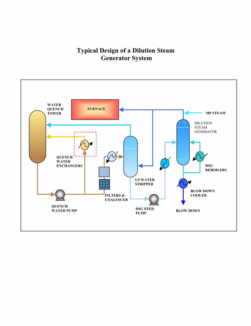
Typical Design of a Dilution Steam Generator System
BLOW DOWN
MP STEAM
DSG REBOILERS
FILTERS & COALESCER
BLOW DOWN COOLER
DILUTION STEAM GENERATOR
FURNACE
DSG FEED PUMP
QUENCH WATER PUMP
QUENCH WATER EXCHANGERS
LP WATER STRIPPER
WATER QUENCH TOWER
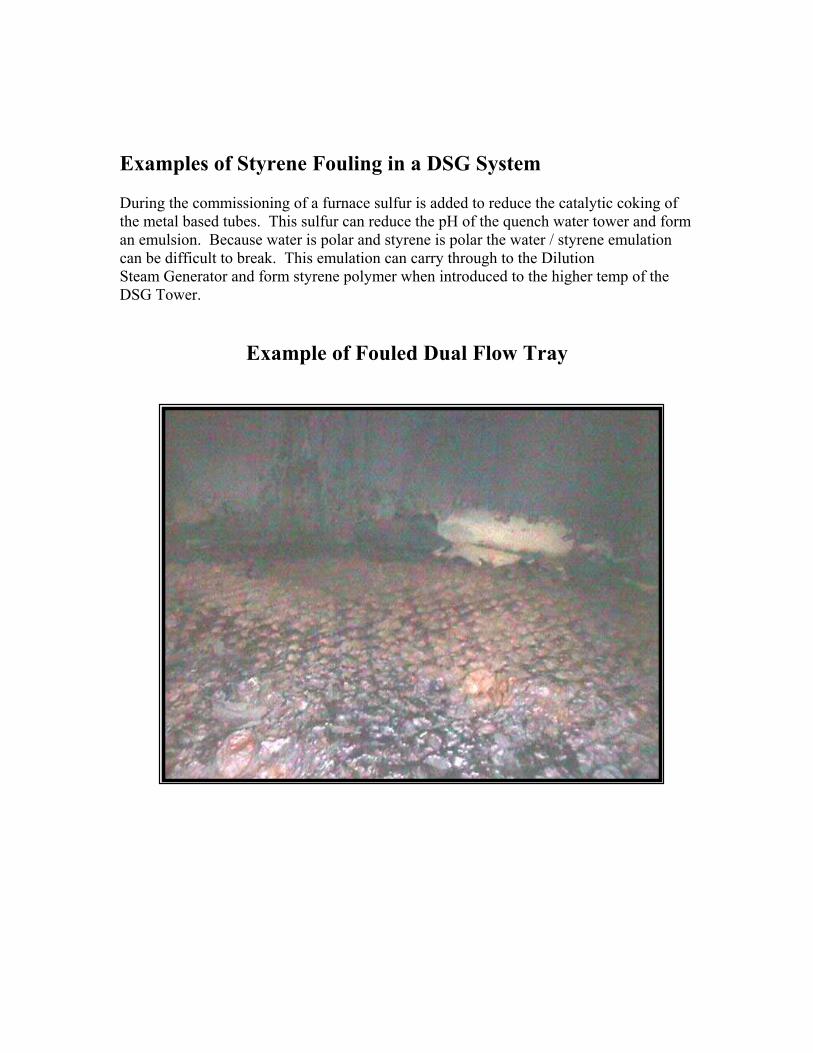
Examples of Styrene Fouling in a DSG System During the commissioning of a furnace sulfur is added to reduce the catalytic coking of the metal based tubes. This sulfur can reduce the pH of the quench water tower and form an emulsion. Because water is polar and styrene is polar the water / styrene emulation can be difficult to break. This emulation can carry through to the Dilution Steam Generator and form styrene polymer when introduced to the higher temp of the DSG Tower.
Example of Fouled Dual Flow Tray
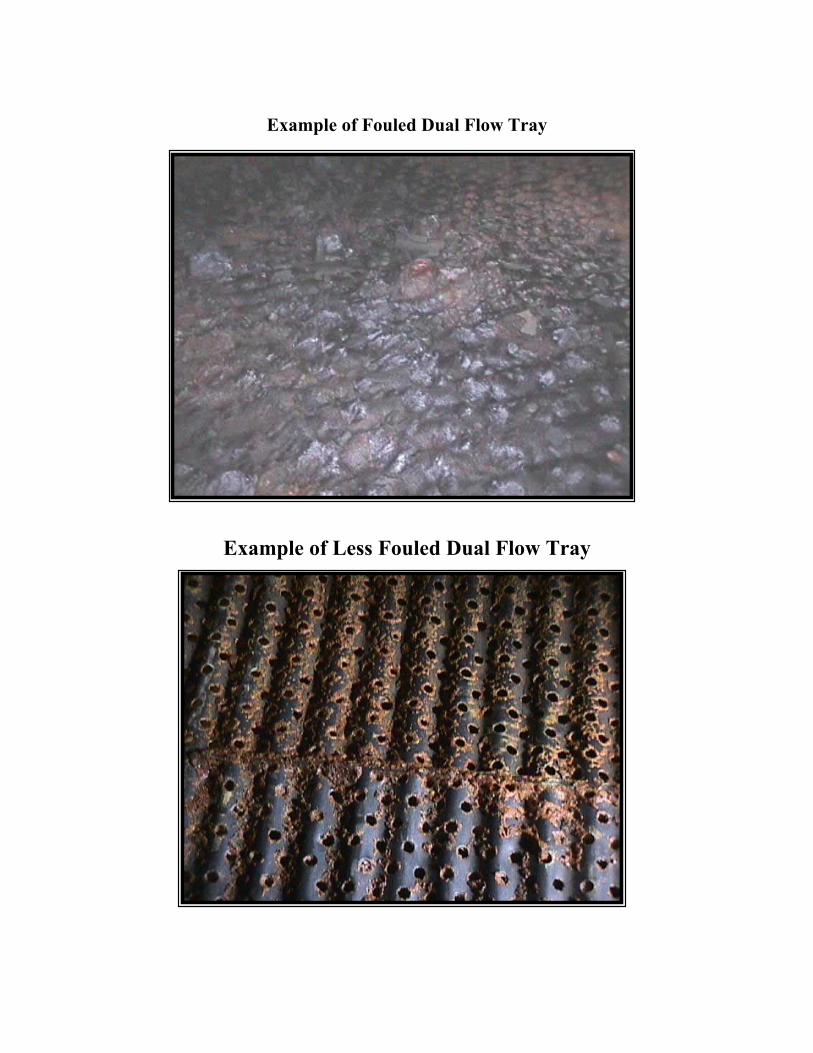
Example of Fouled Dual Flow Tray
Example of Less Fouled Dual Flow Tray
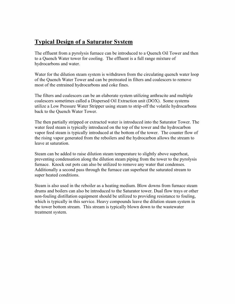
Typical Design of a Saturator System The effluent from a pyrolysis furnace can be introduced to a Quench Oil Tower and then to a Quench Water tower for cooling. The effluent is a full range mixture of hydrocarbons and water. Water for the dilution steam system is withdrawn from the circulating quench water loop of the Quench Water Tower and can be pretreated in filters and coalescers to remove most of the entrained hydrocarbons and coke fines. The filters and coalescers can be an elaborate system utilizing anthracite and multiple coalescers sometimes called a Dispersed Oil Extraction unit (DOX). Some systems utilize a Low Pressure Water Stripper using steam to strip-off the volatile hydrocarbons back to the Quench Water Tower. The then partially stripped or extracted water is introduced into the Saturator Tower. The water feed steam is typically introduced on the top of the tower and the hydrocarbon vapor feed steam is typically introduced at the bottom of the tower. The counter flow of the rising vapor generated from the reboilers and the hydrocarbon allows the stream to leave at saturation. Steam can be added to raise dilution steam temperature to slightly above superheat, preventing condensation along the dilution steam piping from the tower to the pyrolysis furnace. Knock out pots can also be utilized to remove any water that condenses. Additionally a second pass through the furnace can superheat the saturated stream to super heated conditions. Steam is also used in the reboiler as a heating medium. Blow downs from furnace steam drums and boilers can also be introduced to the Saturator tower. Dual flow trays or other non-fouling distillation equipment should be utilized to providing resistance to fouling, which is typically in this service. Heavy compounds leave the dilution steam system in the tower bottom stream. This stream is typically blown down to the wastewater treatment system.
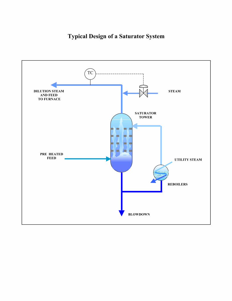
Typical Design of a Saturator System
PRE HEATED FEED
UTILITY STEAM
STEAM
TC
DILUTION STEAM AND FEED
TO FURNACE
SATURATOR TOWER
REBOILERS
BLOWDOWN
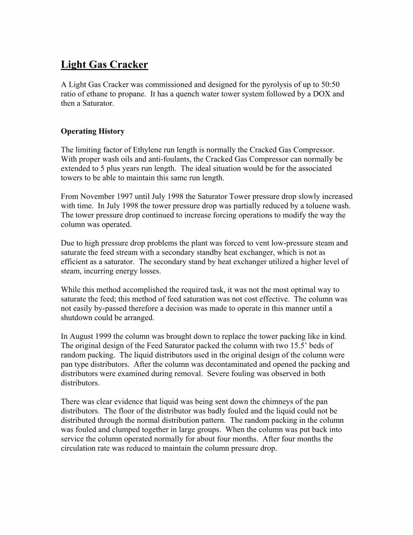
Light Gas Cracker A Light Gas Cracker was commissioned and designed for the pyrolysis of up to 50:50 ratio of ethane to propane. It has a quench water tower system followed by a DOX and then a Saturator. Operating History The limiting factor of Ethylene run length is normally the Cracked Gas Compressor. With proper wash oils and anti-foulants, the Cracked Gas Compressor can normally be extended to 5 plus years run length. The ideal situation would be for the associated towers to be able to maintain this same run length. From November 1997 until July 1998 the Saturator Tower pressure drop slowly increased with time. In July 1998 the tower pressure drop was partially reduced by a toluene wash. The tower pressure drop continued to increase forcing operations to modify the way the column was operated. Due to high pressure drop problems the plant was forced to vent low-pressure steam and saturate the feed stream with a secondary standby heat exchanger, which is not as efficient as a saturator. The secondary stand by heat exchanger utilized a higher level of steam, incurring energy losses. While this method accomplished the required task, it was not the most optimal way to saturate the feed; this method of feed saturation was not cost effective. The column was not easily by-passed therefore a decision was made to operate in this manner until a shutdown could be arranged. In August 1999 the column was brought down to replace the tower packing like in kind. The original design of the Feed Saturator packed the column with two 15.5’ beds of random packing. The liquid distributors used in the original design of the column were pan type distributors. After the column was decontaminated and opened the packing and distributors were examined during removal. Severe fouling was observed in both distributors. There was clear evidence that liquid was being sent down the chimneys of the pan distributors. The floor of the distributor was badly fouled and the liquid could not be distributed through the normal distribution pattern. The random packing in the column was fouled and clumped together in large groups. When the column was put back into service the column operated normally for about four months. After four months the circulation rate was reduced to maintain the column pressure drop.
Picture of Typical Pan Distributor
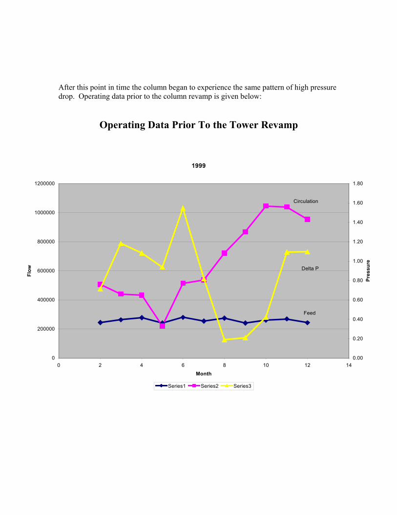
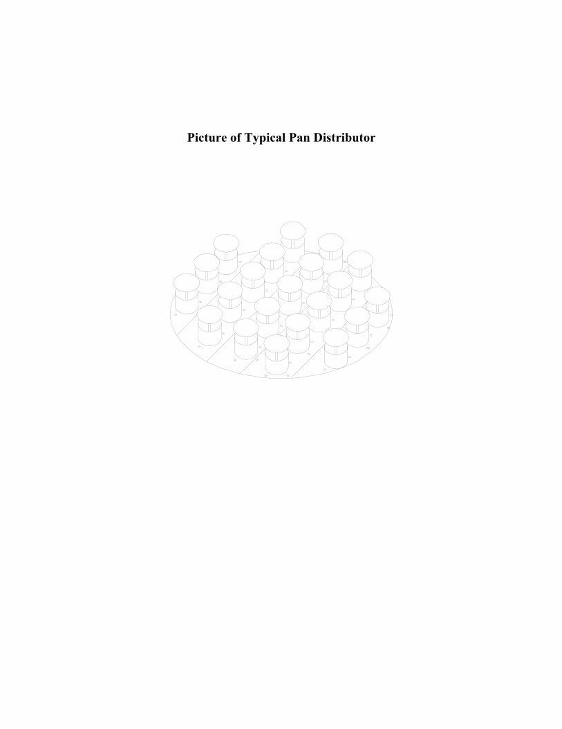
After this point in time the column began to experience the same pattern of high pressure drop. Operating data prior to the column revamp is given below:
Operating Data Prior To the Tower Revamp
1999
0
200000
400000
600000
800000
1000000
1200000
0 2 4 6 8 10 12 14
Month
Flow
0.00
0.20
0.40
0.60
0.80
1.00
1.20
1.40
1.60
1.80
Pressure
Series1 Series2 Series3
Feed
Circulation
Delta P
2000
0
200000
400000
600000
800000
1000000
1200000
0 2 4 6 8 10 12 14
Month
0.00
0.50
1.00
1.50
2.00
2.50
Series1 Series2 Series3
Feed
Circulation
Delta P
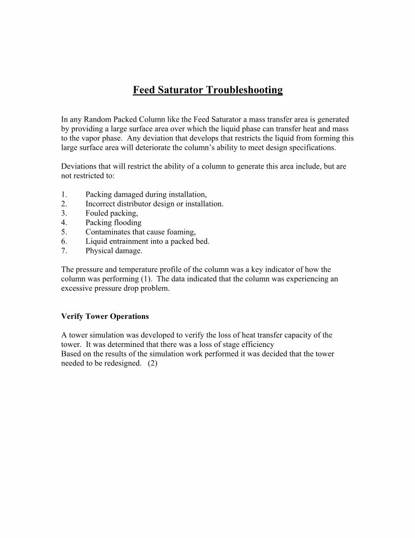
Feed Saturator Troubleshooting In any Random Packed Column like the Feed Saturator a mass transfer area is generated by providing a large surface area over which the liquid phase can transfer heat and mass to the vapor phase. Any deviation that develops that restricts the liquid from forming this large surface area will deteriorate the column’s ability to meet design specifications. Deviations that will restrict the ability of a column to generate this area include, but are not restricted to: 1. Packing damaged during installation, 2. Incorrect distributor design or installation. 3. Fouled packing, 4. Packing flooding 5. Contaminates that cause foaming, 6. Liquid entrainment into a packed bed. 7. Physical damage.
The pressure and temperature profile of the column was a key indicator of how the column was performing (1). The data indicated that the column was experiencing an excessive pressure drop problem. Verify Tower Operations A tower simulation was developed to verify the loss of heat transfer capacity of the tower. It was determined that there was a loss of stage efficiency Based on the results of the simulation work performed it was decided that the tower needed to be redesigned. (2)
Column Revamp The first step of the column revamp was the development of simulation model that would be used to design the column revamp. Operational data was collected and it was modeled. On the basis of the results obtained from the simulation model a design basis was obtained. (15,16,17) Results from the simulation model are given in TABLE 1. TABLE 1 (3)
Saturator Simulation Model Parameters
Simulation Case, Saturator Revamp
Inlet Water Temp, °F 195 Heat from Feed Gas,
MMBTU/Hr 11.44
Stm/HC Ratio .30 Temperature of Mixed
Stream, °F 256
Total Stages Required 5.0 Total Heat Transfer Units
Required 8.0
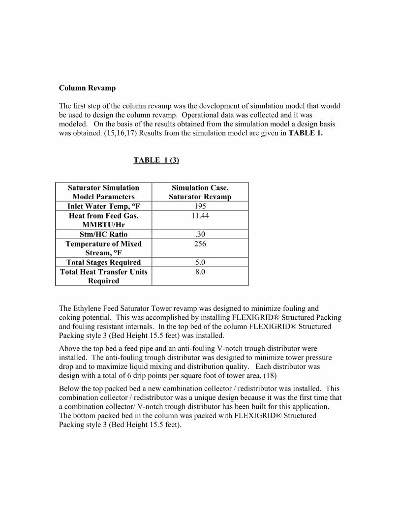
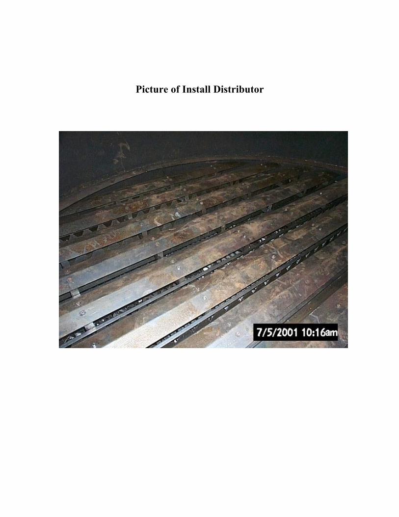
The Ethylene Feed Saturator Tower revamp was designed to minimize fouling and coking potential. This was accomplished by installing FLEXIGRID® Structured Packing and fouling resistant internals. In the top bed of the column FLEXIGRID® Structured Packing style 3 (Bed Height 15.5 feet) was installed.
Above the top bed a feed pipe and an anti-fouling V-notch trough distributor were installed. The anti-fouling trough distributor was designed to minimize tower pressure drop and to maximize liquid mixing and distribution quality. Each distributor was design with a total of 6 drip points per square foot of tower area. (18)
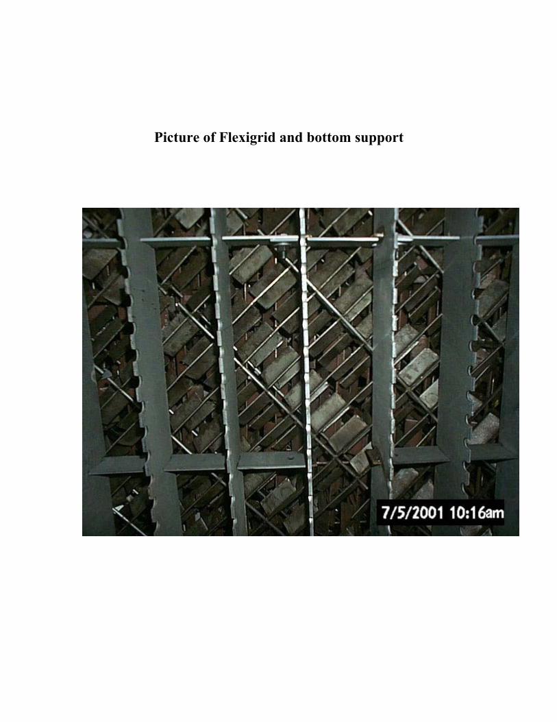
Below the top packed bed a new combination collector / redistributor was installed. This combination collector / redistributor was a unique design because it was the first time that a combination collector/ V-notch trough distributor has been built for this application. The bottom packed bed in the column was packed with FLEXIGRID® Structured Packing style 3 (Bed Height 15.5 feet).
Picture of Install Distributor
Picture of Flexigrid and bottom support
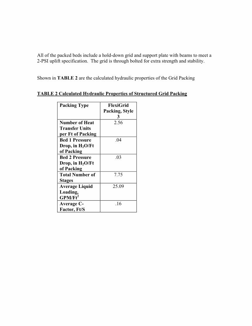
All of the packed beds include a hold-down grid and support plate with beams to meet a 2-PSI uplift specification. The grid is through bolted for extra strength and stability. Shown in TABLE 2 are the calculated hydraulic properties of the Grid Packing TABLE 2 Calculated Hydraulic Properties of Structured Grid Packing
Packing Type
FlexiGrid Packing, Style
3 Number of Heat Transfer Units per Ft of Packing
2.56
Bed 1 Pressure Drop, in H2O/Ft of Packing
.04
Bed 2 Pressure Drop, in H2O/Ft of Packing
.03
Total Number of Stages
7.75
Average Liquid Loading, GPM/Ft2
25.09
Average C-Factor, Ft/S
.16
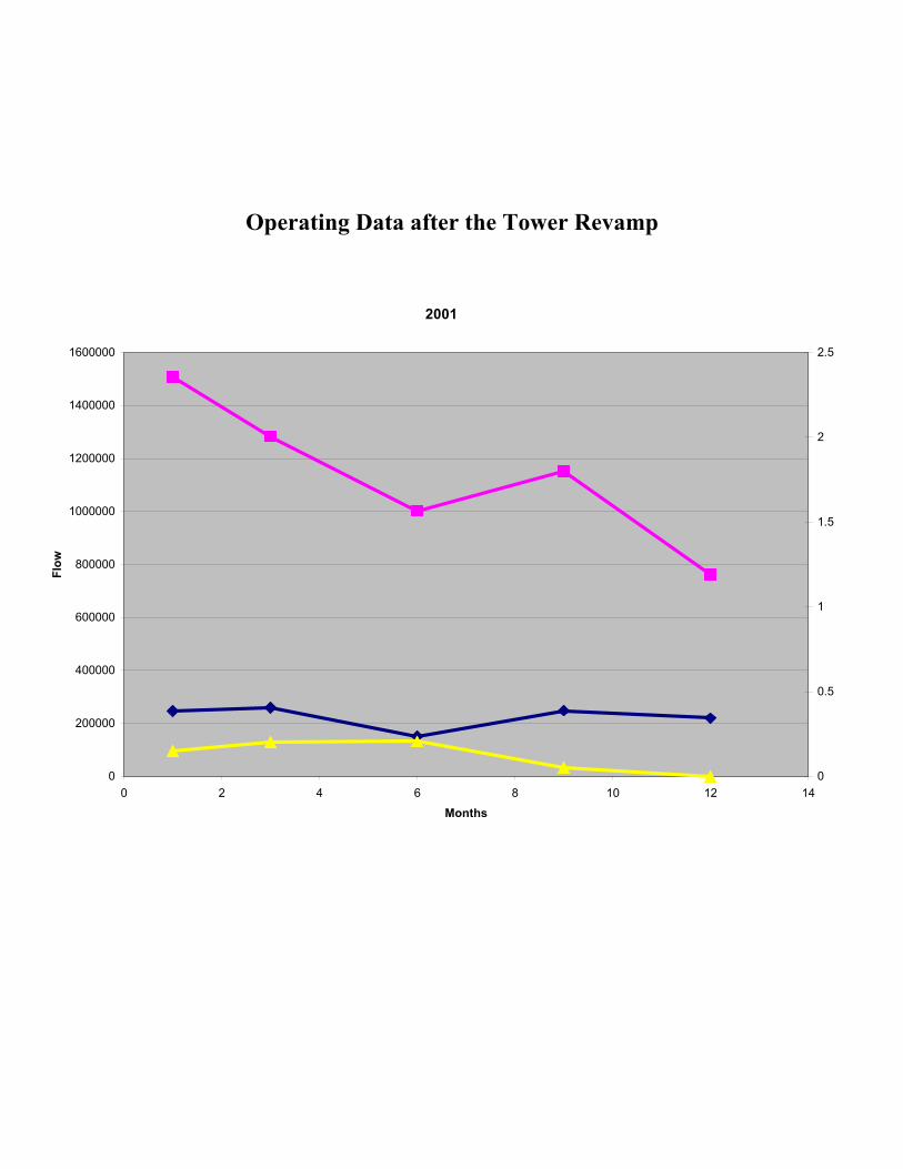
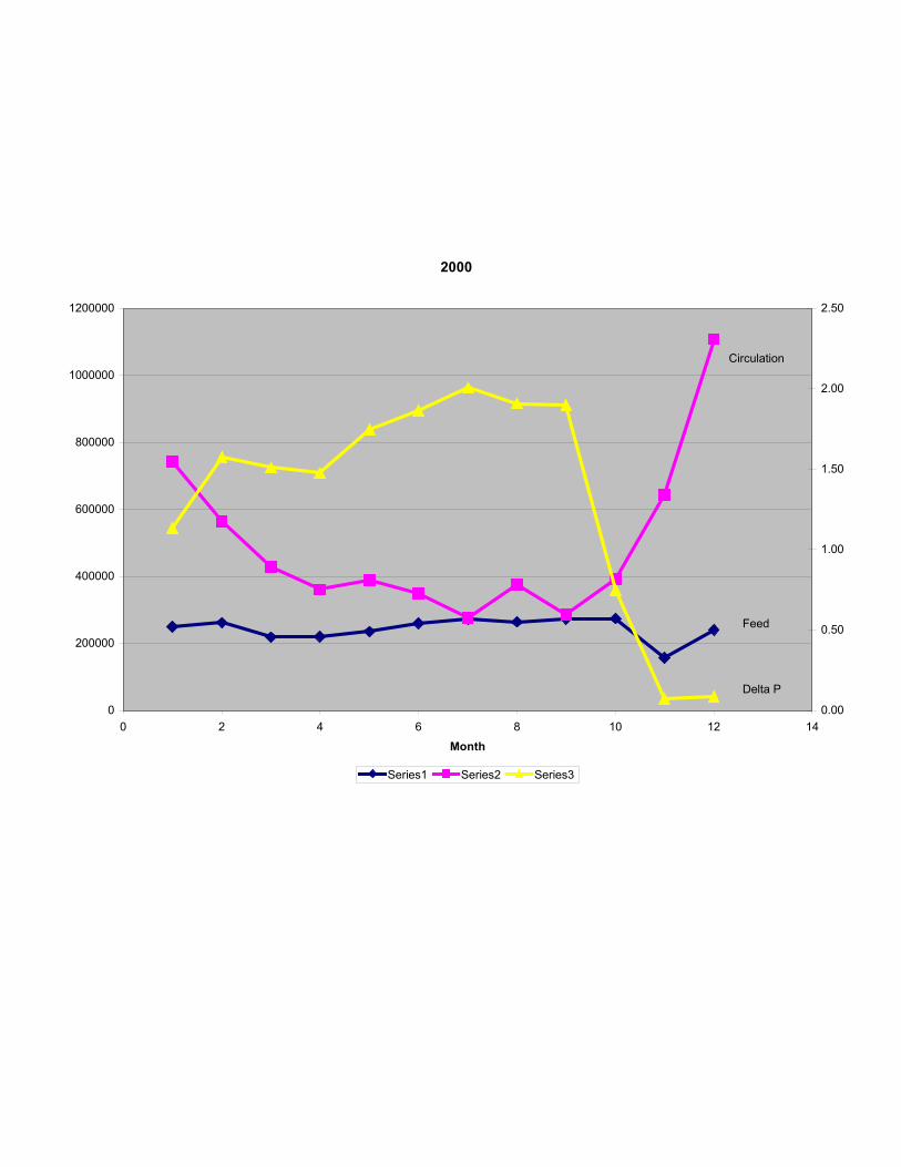
Operating Data after the Tower Revamp
2001
0
200000
400000
600000
800000
1000000
1200000
1400000
1600000
0 2 4 6 8 10 12 1
Months
Flow
0
0.5
1
1.5
2
2.5
4
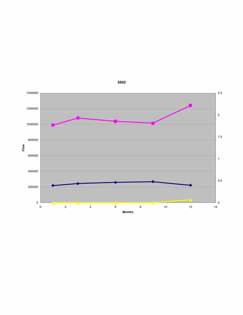
2002
0
200000
400000
600000
800000
1000000
1200000
1400000
0 2 4 6 8 10 12 1
Months
Flow
0
0.5
1
1.5
2
2.5
4
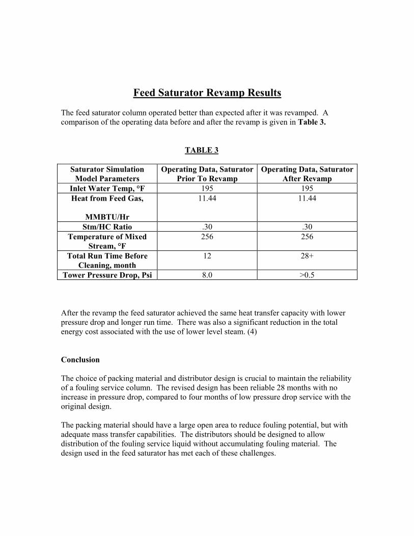
Feed Saturator Revamp Results The feed saturator column operated better than expected after it was revamped. A comparison of the operating data before and after the revamp is given in Table 3. TABLE 3
Saturator Simulation Model Parameters
Operating Data, Saturator Prior To Revamp
Operating Data, Saturator After Revamp
Inlet Water Temp, °F 195 195 Heat from Feed Gas,
MMBTU/Hr
11.44 11.44
Stm/HC Ratio .30 .30 Temperature of Mixed
Stream, °F 256 256
Total Run Time Before Cleaning, month
12 28+
Tower Pressure Drop, Psi 8.0 >0.5 After the revamp the feed saturator achieved the same heat transfer capacity with lower pressure drop and longer run time. There was also a significant reduction in the total energy cost associated with the use of lower level steam. (4) Conclusion The choice of packing material and distributor design is crucial to maintain the reliability of a fouling service column. The revised design has been reliable 28 months with no increase in pressure drop, compared to four months of low pressure drop service with the original design. The packing material should have a large open area to reduce fouling potential, but with adequate mass transfer capabilities. The distributors should be designed to allow distribution of the fouling service liquid without accumulating fouling material. The design used in the feed saturator has met each of these challenges.
REFERENCES 1. “Kister, H. Z. “Distillation Design”, McGraw-Hill Book Company Inc., New York, 1992. 2. “Kister, H. Z., Neves, S. B., Siles, R. C., & Lima R. C “Does Your Simulation Reflect the Real World”,
AIChE Spring National Meeting, Houston, Texas. March 19-23 1997 3. Kister, H. Z., “Troubleshoot Distillation Simulations”, Chemical Engineering Progress, 63-75, June 1995. 4. Kolmetz K, Zygula T, “Resolving Process Distillation Equipment Problems", Prepared for The
5th Annual Regional Olefins Conference, October 31st - November 3rd, 2000, Johor Bahru, Malaysia
1. Zygula, T. M., Fan L. Z. Lee A. T., “New Model for Structured Packing Capacity and Pressure Drop,”
Canadian Chemical Engineering National Conference, October 1995, Quebec City, Quebec. 2. Zygula, T. M., Fan L. Z. Lee A. T., “New Model for Structured Packing Capacity and Pressure Drop,”
Canadian Chemical Engineering National Conference, October 1995, Quebec City, Quebec. 7. Luyben, W. L. “Practical Distillation Control”, Van Nostrand Reinhold, New York, 1992. 8. Khoury, F. M., “Predicting the Performance of Multistage Separation Processes,” Gulf Publishing Company, Houston, TX, 1995. 9. Lockett, M. J., “Easily Predict Structured-Packing HETP”, Chemical Engineering Progress, 60-66, Jan 1998. 10. King, C. J. “Separation Processes”, McGraw-Hill Book Company Inc., New York, 1980 11. Harrison, M. E., France, J. J., “Distillation Column Troubleshooting” Chemical Engineering, April 198 12. Rukovena, F. & Koshy, T. D., “Packed Distillation Tower Hydraulic Design Method and Mechanical Considerations”, Ind. Eng. Chem. Res. 1993, 32, 2400-2407.
13 McCabe, W.L. & Thiele, E. W., “Graphical Design of Fractionating Columns”, ind. Eng. Chem,17, P.605,
1925. 14 Lewis, W. K., “The Efficiency and Design of Rectifying Columns for Binary Mixtures,” Journal of Industrial and Engineering Chemistry, Vol. 14, No. 6, June 1922. 15. Schad, R. C., “Make the Most of Process Simulations”, Chemical Engineering Progress, 21-27, Jan 1998. 16. Hengstebeck, R. J., “An Improved Shortcut for Calculating Difficult Multicomponet Distillations,” Chem
Eng., P. 115, Jan 13, 1969. 17. Kister, H. Z. “Distillation Operation”, McGraw-Hill Book Company Inc., New York, 1990. 18. Bonilla, J. A., “Don’t Neglect Liquid Distributors”, Chemical Engineering Progress, 47-61, Mar 1993. 19. Luyben, W. L. “Practical Distillation Control”, Van Nostrand Reinhold, New York, 1992. 20. Khoury, F. M., “Predicting the Performance of Multistage Separation Processes,” Gulf Publishing Company, Houston, TX, 1995.