{page }€¦ · 5. article 423 – meter installation sequence (page 56 and page 57) revised first...
TRANSCRIPT
0

1
4/1/2014 Revision of the CNP Service Standards Book – (Effective Date 6-1-2014)
1. Article 211.2 – Responsibility for Customer’s Installation (Page 16).
Revised paragraph - Added “(including meter disconnect fuses)”
2. Article 416.3 - Cable Terminal Boxes (page 42)
Note #4 – Added “Doors on both sides will be secured by a three point latch system.”
Note #16 – Added “Bus requirements of two thousand Amps and above will consist of a
tinned copper design.”
3. Article 421.2 – Meter Location (Page 54).
Revised paragraph - Added “by the CNP Primary Metering Manager”
4. Article 421.3 – Meter Location (Page 54).
Revised paragraph - Added “Height of the operating handle is not less than 4 feet and not
more than 7 feet above finish grade.”
5. Article 423 – Meter Installation Sequence (Page 56 and Page 57)
Revised first sentence – “The meter disconnect switch shall not be used as a service
disconnect and shall be locked and sealed under the exclusive control of the Company.”
and Revised Illustration 34
6. New Article 500.6 – Fire Pumps (Page 61)
Added new article – “Fire Pump Services shall be served through a CT Metered Service
(See Instrument Transformer Rated Meter Installation Sequence, Article 517 and
Metering C.T. Box, Article 513.5).”
7. Article 507.2 – Open Wire Drop (Page 67)
Revised Illustration 26, Revised Notes A and B – Meter Equipment Bonding
8. Article 513.2 – Instrument Transformer Installations – Overhead Service (Page 73)
Revised Illustration 24, Revised Notes A and B – Meter Equipment Bonding
9. New Article 513.11 – Meter Equipment Bonding (Page 81)
Added new article and Illustrations 31

2
POWER LINE SAFETY
A foremost concern at CenterPoint Energy is the safety of our customers and employees.
We exercise a great deal of care ensuring that our facilities are safe. But even with our
many precautions, electrical contact accidents have occurred.
REMEMBER, ELECTRIC POWER LINES CAN KILL!
When you are working near power lines or moving tools and equipment (cranes,
scaffolds, derricks, piping, etc.) near power lines, stay alert. The Texas Health and Safety
Code, Chapter 752, prohibits all activities in which persons or equipment MAY come
within six (6) feet of energized overhead high voltage power lines, and Federal
Regulations, Title 29, Part 1919.180(i) and Part 1926.550(a)(15) and 1910.333 require a
minimum clearance of ten (10) feet from power lines. These laws carry both criminal and
civil liabilities. In addition, contractors and owners are legally responsible for the safety
of construction workers under these laws. If you or your company must work near
overhead power lines, contact us at the appropriate service center location (see pages 3-
4). We will help you arrange for the lines to be deenergized and/or moved. Make your
work place a safe one, and remember to LOOK UP AND LIVE near overhead lines. For
information on the above or on electrical safety programs, contact CenterPoint Energy’s
Public Safety Department as listed on page 4.
LAST REVISED 4-1-14

3
FOREWORD
Experience has shown that certain standard practices are necessary to assure every
customer of CenterPoint Energy the best possible electric service. In compiling this
edition of Service Standards for the guidance of customers, contractors, electricians,
architects, and engineers, the basic purpose has been to keep them as simple and
nonrestrictive as possible.
These Service Standards supplement and are subordinate to the terms and conditions for
the delivery of electric service on file in the Company's offices. They are also intended to
supplement and not to be in conflict with the current edition of the National Electrical
Code, National Electrical Safety Code, or of any regulatory authority having jurisdiction.
MANY PROVISIONS IN THESE SERVICE STANDARDS DISCUSS THE
COMPANY’S VIEWS, BASED ON APPLICABLE CODES AND ORDINANCES,
CONCERNING THE MANNER IN WHICH CUSTOMER WIRING AND
EQUIPMENT SHOULD BE INSTALLED AND MAINTAINED BY THE
CUSTOMER. IN EXPRESSING THESE VIEWS, THE COMPANY DOES NOT
INTEND TO IMPLY THAT IT WILL INSPECT CUSTOMER WIRING AND
EQUIPMENT TO ENSURE CONFORMITY WITH THESE VIEWS. THE
CUSTOMER IS SOLELY RESPONSIBLE FOR INSTALLING, INSPECTING AND
MAINTAINING ALL CUSTOMER WIRING AND EQUIPMENT.
The updated Service Standards are located on the CenterPoint Energy website at
http://www.centerpointenergy.com/electricservicestandards
Paper copies will only be provided upon request.
In the text, the substantial changes from the previous issue of the Service Standards have been
underlined and marked, as this paragraph is, with a vertical line in the left margin.

4
COMPANY OFFICES
Customers should contact the nearest Company Office or Service Center listed below
regarding information referred to in the Service Standards. Meter boxes required for
transformer rated installations and service anchorage bolts may be obtained from any of
the Company service centers. Location maps of the Service Centers may be found
starting on page 84.
SERVICE
CENTERS ADDRESS
CITY, STATE
ZIP
TELEPHONE
NO. Boundary
Map
BAYTOWN 333 Ward Road Baytown, TX 77520 (281) 425-7301 P. 85
BELLAIRE 4300 Bissonnet Blvd Bellaire, TX 77401 (713) 945-4201 P. 86
CYPRESS 18018 Huffmeister Cypress, TX 77429 (281) 955-3002 P. 87
FORT BEND 4011 Avenue H Rosenberg, TX 77471 (281) 341-4904 P. 88
GALVESTON 502 27th
Galveston, TX 77550 (409) 765-4165 P. 89
GREENSPOINT 2301 Gears Road Houston, TX 77067 (713) 945-4820 P. 90
H.O. CLARKE 12045 South Main Houston, TX 77035 (713) 945-4340 P. 91
HUMBLE 10010 Old F.M. 1960 Houston, TX 77338 (713) 945-8901 P. 92
KATY 5431 Highway Blvd. Katy, TX 77492 (281) 391-5104 P. 93
SOUTH
HOUSTON
(BLDG. F)
4700 South Shaver Houston, TX 77034 (713) 945-6945 P. 94
SPRING
BRANCH 3401 Brittmoore Houston, TX 77043 (713) 945-4504 P. 95
SUGARLAND 13300 West Bellfort Houston, TX 77099 (281) 561-2967 P. 96
COMPANY OFFICES
CENTERPOINT
TOWER 1111 Louisiana Houston, TX 77002 (713) 207-1111 -
PUBLIC
SAFETY 4700 South Shaver Houston, TX 77034 (713) 945-6706 -
MAJOR
UNDERGROUND 3000 Harrisburg Houston, TX. 77003 (713) 207-4559 -

5
CONTENTS Page
Power Line Safety ........... ............. .............. ............. ............. ............................ ............. 2 Foreword ............ ............. ............. .............. ............. ............. ............................ ............. 3
Company Offices ............. ............. .............. ............. ............. ............................ ............. 4
Table of Contents……………………………………………………………………………….….5-7
Section 100-Definitions Page Article
AMS Meter ......... ............. ............. .............. ............. ............. ............................ ............. 8 ........... 101
Application for Service ..... ............. .............. ............. ............. ............................ ............. 8 ........... 102
Company ........... ............. ............. .............. ............. ............. ............................ ............. 8 ........... 103
Connected Load .. ............. ............. .............. ............. ............. ............................ ............. 8 ........... 104
Customer ............ ............. ............. .............. ............. ............. ............................ ............. 8 ........... 105
Customer Extension.......... ............. .............. ............. ............. ............................ ............. 8 ........... 106
Customer's Installation ..... ............. .............. ............. ............. ............................ ............. 8 ........... 107
Customer's Service Equipment ....... .............. ............. ............. ............................ ............. 8 ........... 108
Distribution Lines ............. ............. .............. ............. ............. ............................ ............. 8 ........... 109
Electric Service ... ............. ............. .............. ............. ............. ............................ ............. 9 ........... 110
Harmonics .......... ............. ............. .............. ............. ............. ............................ ............. 9 ........... 111
Manufactured Home ......... ............. .............. ............. ............. ............................ ............. 9 ........... 112
Meter .................. ............. ............. .............. ............. ............. ............................ ............. 9 ........... 113
Meter Mounting Devices .. ............. .............. ............. ............. ............................ ............. 9 ........... 114
Meter Box ........... ............. ............. .............. ............. ............. ............................ ............. 9 ........... 115
Metering Current Transformer Box .............. ............. ............. ............................ ............. 9 ........... 116
Metering Potential Transformer Box ............. ............. ............. ............................ ............. 9 ........... 117
Meter Loop ......... ............. ............. .............. ............. ............. ............................ ............. 9 ........... 118
Mobile Home ...... ............. ............. .............. ............. ............. ............................ ............. 9 ........... 119
Modular Home ... ............. ............. .............. ............. ............. ............................ ............. 10 ......... 120
National Electrical Code ... ............. .............. ............. ............. ............................ ............. 10 ......... 121
National Electrical Safety Code ..... .............. ............. ............. ............................ ............. 10 ......... 122
Overhead Distribution Areas .......... .............. ............. ............. ............................ ............. 10 ......... 123
Point of Delivery ............. ............. .............. ............. ............. ............................ ............. 10 ......... 124
Rate Schedule Classification .......... .............. ............. ............. ............................ ............. 10 ......... 125
Retail Electric Provider (REP) ....... .............. ............. ............. ............................ ............. 10 ......... 126
Service Cable Tap Box ..... ............. .............. ............. ............. ............................ ............. 10 ......... 127
Service Drop ....... ............. ............. .............. ............. ............. ............................ ............. 10 ......... 128
Service Entrance Conductor ........... .............. ............. ............. ............................ ............. 11 ......... 129
Service Lateral .... ............. ............. .............. ............. ............. ............................ ............. 11 ......... 130
Service Location . ............. ............. .............. ............. ............. ............................ ............. 11 ......... 131
Service Outlet ..... ............. ............. .............. ............. ............. ............................ ............. 11 ......... 132
Service Outlet Location and Data Statement . ............. ............. ............................ ............. 11 ......... 133
Transmission and/or Distribution Service Provider (TDSP) ..... ............................ ............. 11 ......... 134
Type of Service .. ............. ............. .............. ............. ............. ............................ ............. 11 ......... 135
Underground Distribution Areas .... .............. ............. ............. ............................ ............. 11 ......... 136
Underground Street Network Areas .............. ............. ............. ............................ ............. 11 ......... 137
Underground Radial Areas ............. .............. ............. ............. ............................ ............. 12 ......... 138
Underground Residential Distribution Areas ............. ............. ............................ ............. 12 ......... 139

6
Section 200 – General Information
Application for Service ..... ............. .............. ............. ............. ............................ ............. 13 ......... 201
Agreement for Service ...... ............. .............. ............. ............. ............................ ............. 14 ......... 202
Service Outlet Location and Data Statement . ............. ............. ............................ ............. 14 ......... 203
Change in Customer's Wiring Installation ..... ............. ............. ............................ ............. 14 ......... 204
Change in Location of Existing Service Facilities....... ............. ............................ ............. 14 ......... 205
Attachments to Company's Property ............ ............. ............. ............................ ............. 14 ......... 206
Customer Wiring ............. ............. .............. ............. ............. ............................ ............. 15 ......... 207
Grounding ........... ............. ............. .............. ............. ............. ............................ ............. 15 ......... 208
Utilization Voltage ........... ............. .............. ............. ............. ............................ ............. 16 ......... 209
Energizing of Customer's Service... .............. ............. ............. ............................ ............. 16 ......... 210
Responsibility for Customer's Installation ..... ............. ............. ............................ ............. 16 ......... 211
Motor Protection Devices . ............. .............. ............. ............. ............................ ............. 16 ......... 212
Customer Communication or Tone Systems . ............. ............. ............................ ............. 17 ......... 213
Antennas (Radio, Television, Communication, etc.) ... ............. ............................ ............. 17 ......... 214
Customer-Owned Generation Equipment ...... ............. ............. ............................ ............. 17 ......... 215
Electrified Fences ............. ............. .............. ............. ............. ............................ ............. 18 ......... 216
Section 300 - Types of Service
Single-Phase ....... ............. ............. .............. ............. ............. ............................ ............. 19 ......... 301
208/120 volt, 3-wire ......... ............. .............. ............. ............. ............................ ............. 19 ......... 301
240/120 volt, 3-wire ......... ............. .............. ............. ............. ............................ ............. 19 ......... 301
480 volt, 3-wire .. ............. ............. .............. ............. ............. ............................ ............. 19 ......... 301
7,200 or 19,920 volt, 2-wire ........... .............. ............. ............. ............................ ............. 19 ......... 301
Two-Phase .......... ............. ............. .............. ............. ............. ............................ ............. 19 ......... 302
12,470/7,200 volt, 3-wire . ............. .............. ............. ............. ............................ ............. 19 ......... 302
34,500/19,920 volt, 3-wire ............. .............. ............. ............. ............................ ............. 19 ......... 302
Three-Phase ........ ............. ............. .............. ............. ............. ............................ ............. 19 ......... 303
208Y/120 volt network, 4-wire ...... .............. ............. ............. ............................ ............. 19 ......... 303
208Y/120 Volt, 4-wire...... ............. .............. ............. ............. ............................ ............. 19 ......... 303
240/120 volt, 4-wire, delta ............. .............. ............. ............. ............................ ............. 19 ......... 303
480 volt, 3-wire .. ............. ............. .............. ............. ............. ............................ ............. 19 ......... 303
480Y/277 volt, 4-wire ...... ............. .............. ............. ............. ............................ ............. 19 ......... 303
2,400 volt, 3-wire, delta .... ............. .............. ............. ............. ............................ ............. 19 ......... 303
4,160Y/2,400 volt, 4-wire ............. .............. ............. ............. ............................ ............. 19 ......... 303
12,470Y/7,200 volt, 4-wire ............ .............. ............. ............. ............................ ............. 19 ......... 303
34,500Y/19,920 volt, 4 wire ........... .............. ............. ............. ............................ ............. 19 ......... 303
SECTION 400 - RESIDENTIAL AND SMALL COMERCIAL
SELF-CONTAINED METER SERVICE INSTALLATIONS
General Information ......... ............. .............. ............. ............. ............................ ............. 20 ......... 400
Services .............. ............. ............. .............. ............. ............. ............................ ............. 20 ......... 401
Overhead Service ............. ............. .............. ............. ............. ............................ ............. 20 ......... 402
Service Drop ....... ............. ............. .............. ............. ............. ............................ ............. 21 ......... 402
Clearance for Service Drop ............ .............. ............. ............. ............................ ............. 23 ......... 403
Location of Service Outlet ............. .............. ............. ............. ............................ ............. 28 ......... 404
Grouping Service Outlets . ............. .............. ............. ............. ............................ ............. 28 ......... 405
Point of Attachment .......... ............. .............. ............. ............. ............................ ............. 29 ......... 406
Anchorage for Service Drop ........... .............. ............. ............. ............................ ............. 30 ......... 407
Service Entrance Conductors.......... .............. ............. ............. ............................ ............. 30 ......... 408
Transformer Installations on Customer's Premises ...... ............. ............................ ............. 31 ......... 409
Temporary Installations .... ............. .............. ............. ............. ............................ ............. 32 ......... 410
Underground Service ........ ............. .............. ............. ............. ............................ ............. 32 ......... 411

7
Commercial Underground ............. .............. ............. ............. ............................ ............. 32 ......... 411
Mobile Home Parks .......... ............. .............. ............. ............. ............................ ............. 32 ......... 412
Underground Service Laterals in Overhead Areas ...... ............. ............................ ............. 32 ......... 413
Underground Service in Underground Residential Areas ......... ............................ ............. 36 ......... 414
Customer Installed Underground Conductors ............. ............. ............................ ............. 36 ......... 415
Service to Apartments, Townhomes or Condominiums ............ ............................ ............. 40 ......... 416
Meter Loops ....... ............. ............. .............. ............. ............. ............................ ............. 43 ......... 417
Meter Installations ............ ............. .............. ............. ............. ............................ ............. 43 ........ 418
Methods of Installing Meter Mounting Devices .......... ............. ............................ ............. 49 ......... 419
Height of Meters . ............. ............. .............. ............. ............. ............................ ............. 53 ......... 420
Meter Location ... ............. ............. .............. ............. ............. ............................ ............. 54 ......... 421
Meter Pole Installations .... ............. .............. ............. ............. ............................ ............. 55 ......... 422
Meter Installation Sequence ........... .............. ............. ............. ............................ ............. 56 ......... 423
SECTION 500 - LARGE COMMERCIAL INSTRUMENT
TRANSFORMER RATED METER SERVICE INSTALLATIONS
General Information ......... ............. .............. ............. ............. ............................ ............. 59 ......... 500
Services .............. ............. ............. .............. ............. ............. ............................ ............. 61 ......... 501
Overhead Service ............. ............. .............. ............. ............. ............................ ............. 61 ......... 502
Service Drop ....... ............. ............. .............. ............. ............. ............................ ............. 63 ......... 502
Clearance for Service Drop ............ .............. ............. ............. ............................ ............. 64 ......... 503
Location of Service Outlets ............ .............. ............. ............. ............................ ............. 65 ......... 504
Grouping Service Outlets . ............. .............. ............. ............. ............................ ............. 65 ......... 505
Point of Attachment .......... ............. .............. ............. ............. ............................ ............. 66 ......... 506
Anchorage for Service Drop ........... .............. ............. ............. ............................ ............. 66 ......... 507
Service Entrance Conductors.......... .............. ............. ............. ............................ ............. 68 ......... 508
Transformer Installation on Customer's Premises ....... ............. ............................ ............. 68 ......... 509
Temporary Installations .... ............. .............. ............. ............. ............................ ............. 68 ......... 510
Underground Service ........ ............. .............. ............. ............. ............................ ............. 69 ......... 511
Commercial Underground ............. .............. ............. ............. ............................ ............. 69 ......... 511
Underground Service Laterals in Overhead Areas ...... ............. ............................ ............. 69 ......... 512
Meter Installations ............ ............. .............. ............. ............. ............................ ............. 72 ......... 513
Methods of Installing Meter Equipment ........ ............. ............. ............................ ............. 82 ......... 514
Meter Location ... ............. ............. .............. ............. ............. ............................ ............. 83 ......... 515
Meter Seals ......... ............. ............. .............. ............. ............. ............................ ............. 83 ......... 516
Meter Installation Sequence ........... .............. ............. ............. ............................ ............. 84 ......... 517
Service Center Boundaries ............. .............. ............. ............. ............................ ............. 85-96
Lone Star Notification Center……………………………………………………………97

8
SERVICE STANDARDS
CENTERPOINT ENERGY
SECTION 100-DEFINITIONS
100 The following is a list of terms and definitions used in this manual.
101 AMS Meter: Advanced Metering System or Smart Meter used for both
residential and commercial services to measure the electric power and
energy supplied to a customer.
102 Application for Service: The agreement or contract between the Company and
the Customer under which Electric Service is supplied and taken.
103 Company: CenterPoint Energy
104 Connected Load: The combined manufacturer's rated capacity of all motors and
other electric powered devices on the Customer's premises, which may, at the will
of the Customer, be operated.
105 Customer: Any individual, partnership, association, firm, public or private
corporation, or governmental agency now being served or hereafter to be served,
using the Electric Service of the Company at any specified location.
106 Customer Extension: Any addition to the Company's existing distribution
facilities required to render Electric Service to a Customer.
107 Customer's Installation: All wiring, appliances, or apparatus of any kind owned
or operated by the Customer on the Customer's side of the Point of Delivery used
in connection with the Customer's ability to take and use the Electric Service of
the Company.
108 Customer's Service Equipment: The necessary equipment and accessories,
located near the point of entrance of supply conductors to a building, which
constitute the main control and means of disconnecting the supply to that
building. This equipment usually consists of a circuit breaker or a switch and
fuses.
109 Distribution Lines: The Company's lines located along streets, alleys, highways,
or easements on private property when used or intended for use for general
distribution of Electric Service to Customers of the Company.

9
110 Electric Service: The availability of electric power and energy, regardless of
whether any electric power and energy is actually used. The supplying of Electric
Service by the Company consists of maintaining the approximate voltage, phase,
and frequency agreed upon, at the Point of Delivery by means of facilities
adequate for carrying the load which the Company is thereby obligated to supply
by reason of the known requirements.
111 Harmonics: Integer multiples of the fundamental power system frequency (sixty
cycles per second), which have a negative effect on the power system. Harmonics
are generated by the non-continuous manner in which electronically controlled
(non-linear) equipment draws current. See Article 500.1 and 500.2.
112 Manufactured Home: Built on a non-removable chassis (Federal Construction
Safety Standards Act (HUD/CODE) requirement) and designed to be used as a
dwelling, with or without a permanent foundation, when connected to required
utilities. Mobile Homes are defined as manufactured homes in HUD regulations
and the NEC Code also includes mobile homes in their definition of manufactured
homes.
113 Meter: An instrument, or instruments, together with auxiliary equipment, for
measuring the electric power and energy supplied to a Customer.
114 Meter Mounting Devices: The devices owned and furnished by the Customer for
mounting and/or enclosing the Company's self-contained Metering Equipment.
115 Meter Box: A metal box furnished by the Company and installed by the
Customer at the Customer’s expense to house transformer rated meters.
116 Metering Current Transformer Box: A metal box furnished by the Company
and installed by the Customer at the Customer's expense, for enclosing the
Company's metering current transformers where required.
117 Metering Potential Transformer Box: A metal box furnished by the Company
and installed by the Customer at the Customer's expense, for enclosing the
Company's metering potential transformers where required.
118 Meter Loop: The opening in and extension of the Customer's Service Entrance
Conductors provided for installation of the Company's Meter.
119 Mobile Home: A factory assembled structure or structures transportable in one or
more sections that is built on a permanent chassis (integrated frame and axles) and
designed to be used as a dwelling without a permanent foundation where
connected to the required utilities. The metal frame that the house is hauled on is
also the structural floor support of the home and stays as part of the home after
installation. The term Mobile Home includes manufactured homes. The

10
requirements in the NEC treat mobile and manufactured homes the same unless
specifically stated otherwise.
120 Modular Home: Designed, engineered and built in a factory controlled
environment and then carried in sections by special trucks to a building site where
they are put together by a builder on a permanent foundation, similar to regular
home construction. Unlike mobile homes, modular homes do not have integrated
frames and axles. For the purposes of these Service Standards, CenterPoint
Energy will treat Modular Homes and Developer/Contractor Built Homes the
same.
121 National Electrical Code: The current edition of the National Electrical Code
(ANSI/NFPA-70) as published by the National Fire Protection Association.
122 National Electrical Safety Code: The current edition of the National Electrical
Safety Code (ANSI C2) as issued by the Secretariat (IEEE) of the ANSI C2
Committee.
123 Overhead Distribution Areas: The area or areas served by the Company's
overhead distribution system as differentiated from the underground system.
124 Point of Delivery: The point where the electric energy first leaves the line or
apparatus owned by the Company and enters the line or apparatus owned by the
Customer, unless otherwise specified in the Customer's Agreement for Service.
This is not necessarily the point of location of the Company's Meter.
125 Rate Schedule Classification: The classification of the Customer's Electric
Service, the amount of electric power supplied, the rate area and the purpose for
which the Electric Service is to be used.
126 Retail Electric Provider (REP): A person (or company) that sells electric energy
to retail Customers in this state (Texas). As provided in PURA ¶ 31.002(17), a
Retail Electric Provider may not own or operate generation assets. As provided in
PURA ¶ 39.353(b), a Retail Electric Provider is not an Aggregator.
127 Service Cable Tap Box: An enclosure designed with busbars for the purpose of
terminating service entrance conductors from the electric utility point of supply
and for terminating service conductors to individual tenant services.
128 Service Drop: The Overhead Service conductors extending from the Company's
Overhead Distribution System to the Customer's Service Entrance Conductors at
the Point of Delivery.

11
129 Service Entrance Conductors: The wires or bus bars provided by the Customer
extending from the Customer's Service Equipment to the terminals of the Service
Drop or Service Lateral.
130 Service Lateral: The Underground Service conductors between the street and/or
easement, including any risers at a pole or from transformers, and the first point of
connection to the Service Entrance Conductors in a terminal box or Meter.
(Underground Service conductors are owned and maintained by the Customer.)
131 Service Location: Conductors on the utility side of the service point are not
covered by the NEC. CenterPoint Energy (CNP) specifies the location of the
service point. Service entrance conductors go from the Service Point through the
meter socket to the Service Equipment (breakers, fuses or switches), CNP has
equipment specifications and/or service requirements beyond the Code for meter
sockets, metering cabinets, and metering compartments within switchgear,
switchboards and panelboards. See Section 412 and 418.3 of these Service
Standards for use of Self-Contained Meter Pedestals in mobile home parks.
132 Service Outlet: The outside terminal portion of the Customer's Installation to
which the Company's Service Drop is connected.
133 Service Outlet Location and Data Statement: A written statement prepared by
the CenterPoint Energy representative for the guidance of the Company and the
REP, or his representative. This statement shows the estimated load to be served,
the Type of Service which the Company proposes to make available, and the
agreed location for the Customer's Service Outlet at the specific premises under
consideration.
134 Transmission and/or Distribution Service Provider (TDSP): An Entity that
owns or operates for compensation in this state (Texas) equipment or Facilities to
transmit and/or distribute electricity, and whose rates for Transmission Services,
Distribution Services, or both is set by a Governmental Authority.
135 Type of Service: The characteristics of Electrical Service described in terms of
frequency, phase, nominal system voltage and number of wires.
136 Underground Distribution Areas: Those areas where Electrical Service is
supplied by the Company from its underground distribution facilities as described
in Articles 135, 136, and 137.
137 Underground Street Network Areas: Those areas designated by the Company
where established 208Y/120 volt street secondary network systems are in
operation.

12
138 Underground Radial Areas: Those areas where Electric Service is supplied by
the Company from its underground distribution facilities connected to a radial
supply.
139 Underground Residential Distribution (URD) Areas: Those residential areas
where special contractual arrangements have been made for single-phase 240/120
Volt underground service to all Customers in a subdivision or specified area.

13
SECTION 200 - GENERAL INFORMATION
200 This section contains information on how to obtain service and outlines standards
to be followed to ensure safe and reliable service. Consequently, the Company
reserves the right to refuse service to any installation not meeting these
Standards.
201 Application for Service
201.1 Requests for service or changes in service may be made by calling the
CenterPoint Energy Customer Service Department at (713) 207-2222 or 1-800-
332-7143 to verify address and obtain an ESI-ID. The Customer must then select
and contact a certified Retail Electric Provider to make application for service. A
list of approved retail energy providers can be found by calling 1-866-PWR-
4TEX (1-866-797-4839), or on the internet at www.powertochoose.org. All
requests for service or changes in service should be made as early as possible.
Customers requesting either overhead or underground electric service may be
required to grant permanent easements for these facilities. This easement
document outlines specific obligations to keep the easement free from
obstructions and appurtenances.
201.2 It will facilitate the prompt rendering of Electrical Service to new Customers or
additional Electric Service to existing Customers if the following information is
supplied to the Service Consultant during the early planning stages of the project.
- Exact Location of premises, including building’s street address or lot and block
number and name of subdivision, if building numbers or street names have not
been established. THE STREET ADDRESS, WHEN ESTABLISHED,
SHALL BE DISPLAYED AND SHALL BE VISIBLE FROM THE
STREET. IN ALL CASES, APARTMENT ADDRESSES ARE TO BE
PLACED ON OR ADJACENT TO THE APARTMENT DOOR (NOT IN
OR ON WINDOWS)
- The Type of Service desired including voltage, phase or special requirements
of the load.
- An Electrical Load Analysis. (General nature and estimated amount of load,
such as lighting, motors, air conditioning and heating applications, including
voltage, rating and number of Motors and other items to be used.)
- The approximate date the Customer's Installation will be ready for service.
- The name of the Electrical Contractor performing the installation.
- A site plan.
- A warranty deed, if easements are required.

14
202 Agreement for Service
The Company will supply to a Customer, at any specific premise, only one of the
Types of Service listed in Section 300 of the Service Standards and such service
will be covered by one agreement for service.
The Customer's Installation is to be so arranged that all Electric Service under one
agreement for service can be supplied at one Point of Delivery and measured
by one meter.
203 Service Outlet Location and Data Statement
Before work is started on the Customer's installation, the Customer or his
Contractor shall secure from the Company a Service Outlet Location and Data
Statement for guidance in making the installations. This statement will specify the
service facility arrangement necessary to secure service connection, including the
Type of Service which the Company proposes to make available and the specified
location for the Customer's Service Outlet.
204 Change in Customer's Wiring Installation
When planning additions or alterations to the Customer's installation, the
Customer shall notify the Company and their Retail Electric Provider since most
building alterations or rewiring work will necessitate some change in the
Company's facilities. The Customer or his Contractor shall not assume that a
remodeled or increased service will be served from the same Point of Delivery as
the old service. Additional wiring shall comply with the current National
Electrical Code or the adopted code by the authority having jurisdiction. In
localities having electrical ordinances, approval by the city inspecting authority
having jurisdiction will be required before the Company is permitted to reconnect
the service.
205 Change in Location of Existing Service Facilities
The Company may require a Customer to pay the expense of change in the Point
of Delivery, location of Service Drop, or location of Metering Equipment when
such changes are requested by the Customer. Where a service pole or poles must
be set to provide proper clearance around or over driveways, garages, trees, or
other obstructions on the premises, a charge shall be made for each service pole
required.
206 Attachments to Company's Property
The Company's street light standards, poles, wires, towers, structures, and other
facilities are provided for the exclusive purpose of supplying Electric Service.
Any non-authorized radio or television equipment or wires, ropes, signs, banners,
etc., are prohibited from being attached to poles, wires, towers, or structures or
located near enough to such facilities as to present a hazard. The Company
reserves the rights to remove all such hazards without notice.
When the Company’s poles with approved customer equipment attached need to
be relocated or replaced, the Customer is responsible for relocating all of their
equipment at their cost within 30 days of receipt of written notification.

15
207 Customer Wiring
207.1 The Customer’s wiring installation should conform to the requirements of the
National Electrical Code and the National Electrical Safety Code, State,
Municipal requirements in force at the time the installation is made and the
Company Service Standards as to Service Outlet Location, Service Drop, Meter
Location and height, etc. Compliance with all such codes and requirements is the
sole responsibility of the Customer for all Customer wiring and equipment. The
Company does not inspect Customer wiring and equipment, and the supplying of
Electric Service by the Company does not mean that Customer wiring and
equipment has been inspected or approved by the Company.
207.2 Certain city ordinances prohibit the Company from supplying Electric Service to
a Customer until a permit has been received by the Company from the proper City
authority.
207.3 For the Customer's and Company's mutual safety, the Company reserves the right
to decline to serve or continue to serve any installation that is declared by the
Company or the proper authorities to be unsafe and a hazard. In all such cases, the
Customer or a representative will be notified, wherever possible, and a reasonable
period of time allowed for the correction of such unsafe condition. In no case,
however, does the supplying of Electric Service by the Company indicate that the
Company assumes any responsibility for the Customer’s wiring or its safety or
adequacy.
208 Grounding
208.1 To assure maximum safety, the Customer should provide an adequate and
permanent grounding conductor attached to the neutral terminal of the main-line
switch, or where a main-line switch is not required, the breaker box.
208.2 For all Service Entrance Conductors the grounded neutral conductor should be
electrically continuous from the Service Outlet through the Meter Loop. The
grounded conductor should be positively identified either by use of white
insulation, white paint at terminals, or by other suitable methods.
208.3 The grounding conductor shall be sized and installed in accordance with
Illustration 1 on Page 22 and the National Electrical Code.

16
209 Utilization Voltage
209.1 A clear understanding of utilization voltage is essential for optimum operation of
utilization equipment. Utilization voltage is the voltage at the line terminals of
the utilization equipment. It should not be confused with service voltage which is
the voltage at the point where the electric systems of the supplier and user are
connected, which is the Point of Delivery. Utilization voltage may vary with each
location of utilization equipment. In practice the service voltage may differ from
the nominal system voltage which is designated voltage class rather than a
specific voltage.
209.2 It is recommended that the Customer install Transient Voltage Surge Suppression
at the line terminals or receptacles for all critical equipment and sensitive
electronic appliances. Transient Voltage Surge Suppressors should be UL 1449
listed and are readily available from electrical contractors and retail stores.
210 Energizing of Customer's Service
For the mutual protection of the Customer and the Company, only authorized
employees of the Company are permitted to make and energize the connection
between the Company's Service Drop and the Customer's Service Entrance
conductors.
211 Responsibility for Customer's Installation
211.1 The Company will not perform any electric wiring on the Customer's premises
other than the installation of its Service Drop and Metering Equipment, as
described in this manual.
211.2 The Customer is solely responsible for any accidents, fires, or failures (including
meter disconnect fuses) resulting from the condition and use of his wiring
installation or equipment.
211.3 The Customer should check carefully to see that phase connections and rotation
are correct when first starting motors and to see that three-phase motors are not
"single-phasing."
211.4 Customers requiring service at voltages of 7,200 volts and above must provide at
the Point of Delivery a Company-approved disconnecting means and proper
overload and short-circuit protection. Customers shall submit plans in accordance
with CenterPoint Energy Specification 600-007-231-458 to Electric Engineering
for approval.
212 Motor Protection Devices
212.1 All motors need protective devices to safeguard the motors, the wiring, and the
equipment they operate from damage that might be caused by overloading, short
circuits, single-phasing, large fluctuations in voltage, etc.

17
212.2 The Company's Power System is designed to provide high speed reclosing of its
protective devices following power interruptions resulting from lightning or other
causes. In most instances these power interruptions will be of extremely short
duration. The Company recommends that under-voltage motor protection be
equipped with time delay devices to permit motors to ride through these short
duration interruptions.
212.3 It is recommended that overcurrent protective devices be provided in each phase
to afford some motor-running protection of three-phase, three-wire motors against
“single-phasing” unless complete protection for single-phase operation is
provided, such as a relay which will detect a “single-phasing” condition.
212.4 Protective devices of the kind described above are readily available through most
electrical contractors. The Company will advise the Customer regarding the type
required for any particular case.
213 Customer Communication or Tone Systems
Modulated carriers or pulsed carrier systems shall not be impressed upon the
electric service conductors, furnished by the Company, for conveying
intelligence, for control purposes or for signal purposes beyond the Customer's
premises. In instances where carriers are impressed upon the Customer's privately
owned electric distribution system, the owner of such systems shall provide filters
to isolate the carrier signals from the Company's facilities.
214 Antennas (Radio, Television, Communication, Etc.)
Customers are cautioned to check the location of power lines in the immediate
vicinity where an antenna is to be installed and to remember the danger to life and
property should any part of the antenna come into contact with a power line
during inclement weather.
215 Customer-Owned Generation Equipment
215.1 Customer generation equipment may be installed and operated after application
for such installation and operation has been received and approved by CenterPoint
Energy. Customer generation equipment will be classified as either non-parallel
or parallel generation.
215.2 Non-parallel generation equipment must operate separately from the Company's
facilities. Examples include emergency power for homes, schools, hospitals,
businesses, computer installations, and other utilities (water, wastewater,
telephone, and gas). Non-parallel generation equipment will operate under
specific terms and conditions as established in the latest revision of the
CenterPoint Energy Specification 007-231-82.

18
215.3 Customers may operate generation equipment in parallel with the Company
distribution system under specific terms and conditions as established in the latest
revision of CenterPoint Energy specification 007-231-76.
215.4 Before Customer-owned generating equipment may be interconnected to the
Company system, application must be made and approved. (See CenterPoint
Energy specification 007-231-76.) For more information, contact the Service
Consultant at the nearest Company Office. (See page 4)
215.5 Customers may not install or use any transfer switch on the high side (CenterPoint
Energy side) of the meter or any transfer switch between the meter and the meter
socket jaws.
215.6 Customer owned standby generators that are to be permanently installed, must be
located on the load side (customer side) of the meter, behind the main breaker
(switch) and must have a transfer switch installed that prevents tying the running
generator into the CenterPoint Energy system, whether the CNP lines are hot or
dead.
216 Electrified Fences
Use of the Company's electric service to energize fencing or to energize devices
which simultaneously energize fencing is prohibited.

19
300 TYPES OF SERVICE
• Not Available • Company option
• Underground Street Network only
• Spot locations with existing 208/120 V supply (Downtown Network)
• Less than 10 kVA
• All equipment must be for use at 208 V
• Standard Service • Company option
• Less than 334 kVA • Locations with existing 240/120 V supply
• Less than 250 kVA
• Governmental entities for lighting only • Governmental entities for lighting only
• Less than 50 kVA • Less than 50 kVA
• No paralleling of transformers allowed • No paralleling of transformers allowed
• Company option • Not Available
• More than 200 kVA, but less than 334 kVA
• In accordance with CenterPoint Energy Specification 600-007-231-458
• Company option • Not Available
• More than 200 kVA, but less than 334 kVA
• Load must be balanced between phases
• In accordance with CenterPoint Energy Specification 600-007-231-458
• Commercial and industrial customers with a total demand of at least 50 kVA or one 3-phase motor 3-hp or more
• Not generally available to residential customers
• For 3-phase, 4-wire, customer must wire for a 3-phase, 4-wire meter • For 3-phase, 3-wire service, customer must provide a fourth wire for metering purposes and for a bond, which shall run from the weatherhead
to the Customer’s switchgear and be sized in accordance with the National Electrical Code, minimum #6 copper
• Standard Service • Standard Service
• Permanent Service only • Permanent Service only
• Balanced 3-phase load • Balanced 3-phase load
• All equipment must be rated for use at 208 V • All equipment must be rated for use at 208 V
• All phase conductors must be the same size • All phase conductors must be the same size
• Single-phase load equally divided • Single-phase load equally divided
• More than 75 kVA and maximum 300 kVA Pad Mounted Installation
• Maximum cable size parallel 500 KCMIL Cu. • Minimum 301 kVA and maximum 1000 kVA.
• Secondary conductors more than 50 feet long Network Area (Company option)
require Company review to maintain required voltage • More than 10 kVA
• Available in spot locations with existing 208Y/120 V
• Standard Service • Company Option
• Max load 70kVA single-phase, 170kVA three-phase. Total 240kVA • Max load 100kVA single-phase, 250kVA. Total 350kVA
• Phase wire permanently identified, power orange • Pad mounted transformer installation (Two URD)
• Secondary conductors more than 50 feet long require Company
review to maintain required voltage
• Company Option • Company Option
• All phase conductors must be the same size • All phase conductors must be the same size
• More than 75 kVA and maximum 501 kVA • More than 501 kVA and maximum 3,000 kVA
• Standard Service • Standard Service
• All phase conductors must be the same size • All phase conductors must be the same size
• More than 75 kVA and maximum 501 kVA • More than 501 kVA and maximum 3,000 kVA
• Company option • Company option
• More than 150 kVA and maximum 501 kVA • 12 kV area only
• More than 501 kVA and maximum 5,000 kVA
• Company Option • Company Option
• More than 150 kVA and maximum 501 kVA • More than 501 kVA and maximum 5,000 kVA
• Company option • Company option
• More than 200 kVA • More than 200 kVA
• In accordance with CenterPoint Energy Specification 600-007-231-458 • In accordance with CenterPoint Energy Specification 600-007-231-458
• Available in padmounted metering configuration
• Company option • Company option
• More than 200 kVA • Not available in dedicated 35kV underground system
• In accordance with CenterPoint Energy Specification 600-007-231-458 • More than 200 kVA
• Available in padmounted metering configuration
• In accordance with CenterPoint Energy Specification 600-007-231-458
240/120 V
480 V
3-wire
3-wire
2-wire
4-wire
grd neutral
4-wire
grd neutral
4-wire
grd neutral
480 V
240/120 V,
delta
4-wire
grd neutral
3-wire
34,500Y/19,920 V
4,160Y/2,400 V
2,400 V
480Y/277 V
12,470Y/7, 200 V
SECTION 300 - TYPES OF SERVICE
4-wire
grd neutral
3-wire
12,470/7,200 V
OR
34,500/19,920 V
3-wire
-
3-wire
2-wire7,200 or 19,920 V
OVERHEAD UNDERGROUNDTYPE
301 - SINGLE PHASE
302 - TWO PHASE
303 - THREE PHASE
208Y/120 V4-wire
grd neutral
208/120 V

20
SECTION 400 - RESIDENTIAL AND SMALL COMMERCIAL SELF
CONTAINED METER SERVICE INSTALLATIONS
400 GENERAL INFORMATION
The Customer’s wiring installation should conform to the requirements of
the National Electrical Code and the National Electrical Safety Code, State,
Municipal requirements in force at the time the installation is made and the
Company Service Standards as to Service Outlet Location, Service Drop,
Meter Location and height, etc. Compliance with all such codes and
requirements is the sole responsibility of the Customer for all Customer
wiring and equipment. The Company does not inspect Customer wiring and
equipment, and the supplying of Electric Service by the Company does not
mean that Customer wiring and equipment has been inspected or approved
by the Company.
General requirements detailed in Section 200 governing service installations
are available from the Company's Service Consultants in the area.
Customers or customer's representative should contact the Service
Consultants as early as possible to ensure that adequate time is allowed for
the preparation of individual specifications, cost estimates, ordering
equipment and acquiring easements, if required.
401 SERVICES
The Company will supply to a Customer, at each Point of Delivery, only one
of the Types of Service listed in these Service Standards. The Customer's
installation is to be so arranged that the Company can measure the power
used by the Customer with one meter.
OVERHEAD SERVICE
402 SERVICE DROP
402.1 Requirements: The Company will install one Service Drop from the Company's
Distribution Lines to the Customer's Service Outlet. For Service Entrance
Conductors sized 200 Amperes or less, and Service Voltages of 240 volts, a
twisted Service Drop will be used. (See Illustration 2 - Typical Residential
Service Mast, page 21). Open wire type Service Drops must be used for 480 volt
and 208 volt services for conductor sizes larger than 4/0 aluminum. (See
Illustration 3 - Typical Open Wire Service Mast, page 21) Where Service Outlets
are grouped (See Article 405), the combined ampacity of all Service Outlets shall
determine the type of Service Drop. (See Illustration 1 – Arrangement of
Overhead Service Equipment, page 22)

21

22

23
402.2 Service Drop Length: The maximum length of Service Drop which the Company
will install will be governed by the amount and Type of Service and will be
determined by Company personnel. Allowable voltage drop and mechanical
factors, determined by the size and number of wires, impose limits on its length.
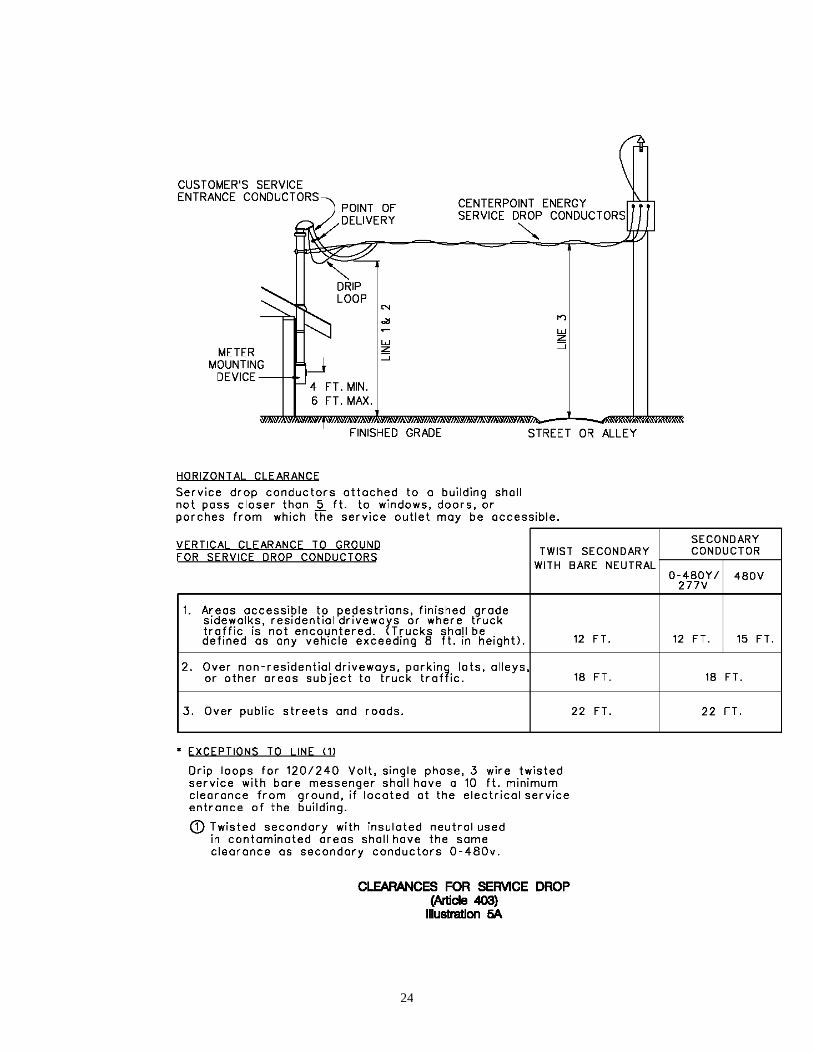
403 CLEARANCE FOR SERVICE DROP
403.1 Service Drop Conductors, when not in excess of 600 volts, shall have the
minimum clearances at the lowest point of the drip loop or service drop as
required by Illustrations 5A and 5B - Clearances for Service Drop, next page.
403.2 If an existing service is being modified and any revision in the service entrance
raceway is made, the modified service must conform to the heights and clearances
outlined in Illustrations 5A and 5B - Clearances for Service Drop, next page.
403.3 Service drop shall be located no closer than 5 ft. to windows, doors or porches
from which the Service Outlet may be accessible. This clearance is an NESC
requirement and must be maintained.
24

25

26
403.4 Clearance near or around swimming pools shall adhere to Illustration 6 -
Clearances of Wires, Conductors or Cables Installed Around Swimming Areas.

27
403.5 Service Drops must be free of contact with trees. The customer shall trim all trees
required to provide the necessary clearances. Customer should not trim trees
around primary lines.
403.6 Under no circumstances will the Company attach its Service Drop to an
intermediate structure installed by the Customer between the Company's
Distribution Lines and the Customer's Service Outlet.
403.7 Where a service pole or poles must be set to provide proper clearance around or
over driveways, garages, trees, or other obstructions on the premises, a charge
shall be made for each such service pole required.

28
404 LOCATION OF SERVICE OUTLET
404.1 Located at a sufficient height above ground level to provide proper clearances for
the Service Drop, as required by Illustration 5A - Clearances for Service Drop,
page 24. For the twisted type Service Drop, the Service Outlet shall not be more
than 18" horizontally, and not less than 6" nor more than 12" above the Point of
Attachment see Illustration 1 - Arrangement of Overhead Service Equipment,
on page 22).
For the open wire type Service Drop, the Service Outlet shall not be less than 6"
nor more than 18" horizontally and not less than 6" nor more than 12" above the
Point of Attachment. (See Illustration 3 - Typical Open Wire Service Mast, on
page 21).
404.2 Located so that the Company's Service Drop or the Customer's Service Entrance
Conductors are not closer than 12" to telephone or communication wires, whether
in the air or on the building.
405 GROUPING SERVICE OUTLETS
If a building has an established Service Outlet location which conforms to the
above requirements, then any additional Service Outlets shall be located within
18" of this established point (See Illustration 17A – Grouping of Service Outlets),
next page. NO MORE THAN SIX WEATHERHEADS SHALL BE
INSTALLED AT EACH SERVICE OUTLET LOCATION. If the established
location does not conform to these requirements, then all Service Outlets shall be
combined at a satisfactory point specified by the Company. When the total cross-
sectional area of all Service Entrance Conductors at a service outlet location
exceed 2-1,000 KCMIL per phase, a bus bar type weatherhead must be used. (See
Illustration 17B – Typical Commercial Open Wire Service Installation), next
page.

29
406 POINT OF ATTACHMENT
406.1 Provisions: A solid Point of Attachment for supporting the Service Drop on the
building shall be provided by the Customer at a point which will comply with the
provisions of ARTICLE 402. The Point of Attachment shall not be more than
25 feet above ground, unless a greater height is required for proper clearance
(See Illustration 1 - Arrangement of Overhead Service Equipment, page 22).
Company personnel will specify on the Service Outlet Location, the height of the
Point of Attachment if it must be less than the minimum or greater than 25 ft.
above grade.
406.2 Clearances: Where the required heights and clearances specified above cannot be
maintained, the Customer shall provide an extension support, which is of a
permanent nature and of sufficient strength to support the Service Drop at the
required minimum clearance. In such cases, the Customer's Service Outlet is to be
located above the service support at a height which will permit the required
clearances. A typical service mast installation is shown in Illustration 2 - Typical
Residential Service Mast, on page 21. In such an installation, 2" or larger
galvanized iron conduit, 2" or larger intermediate metal conduit, or 3" or larger
rigid aluminum conduit shall be used. If a Service Mast will not have sufficient
strength to properly support the Service Drop, installation of a service bracket will
be required.

30
407 ANCHORAGE FOR SERVICE DROP
407.1 Installation: Where the building is of wood construction and permits use of a
screw hook and the structure furnished by the Customer is capable of
withstanding a pull of 300 lbs., the twisted Service Drop support will be furnished
and installed by the Company. Where installation of a screw hook is not practical,
the Customer shall install the Service Drop support in accordance with ARTICLE
407.2. Where an open wire Service Drop is to be used, the Customer shall install
the Service Drop support in accordance with ARTICLE 407.3. The Type of
Service Drop (twisted or open wire) to be installed shall be determined in
accordance with ARTICLE 402. The service drop support must be installed as
securely as possible to minimize damage to the installation from storms, falling
branches, or other hazards.
407.2 Twisted Service Drop: For a twisted Service Drop, when impractical to use a
screw hook, the Customer shall install one 5/8" galvanized machine bolt of
sufficient length for the threaded end of the bolt to extend 2" beyond the surface
of the wall and so installed that it shall be capable of withstanding a pull of 300
lbs.
407.3 Open Wire Drop: For an open wire Service Drop the Customer shall install a
secondary rack fastened to his structure with two 5/8" galvanized machine bolts
of sufficient length for the threaded end of the bolt to extend 2" beyond the
surface of the wall and so installed that each bolt will be capable of withstanding
a pull of 300 lbs. The bolts shall be installed vertically 16" apart with the bottom
bolt not less than 12' - 0" nor higher than 23' - 4" above ground level. When
required ground clearance cannot be obtained otherwise, the Customer's
Contractor shall secure written permission from the Company to install the bolts
horizontally with the same spacing as for vertical installation. The Company will
supply the bolts and rack when requested by the customer. See Illustration 3-
Typical Open Wire Service Mast, page 21.
408 SERVICE ENTRANCE CONDUCTORS
The Service Entrance Conductors, as defined in ARTICLE 127 may be installed
in schedule 40 or greater rigid non-metallic conduit, rigid metal conduit, electrical
metallic tubing(EMT) or intermediate metal conduit except where subject to
physical damage, such as near a parking area, driveway or gate. Only schedule 80
rigid non-metallic conduit, rigid metal conduit or intermediate metal conduit may
be used for the service entrance conduit where subject to physical damage
see Illustration 10- Arrangement of Meter Mounting Device, next page.
The Service Entrance Conductors shall be provided with a weatherproof entrance
fitting where they extend from the Customer’s conduit or raceway. The
connection to the Metering Mounting Device shall be watertight.
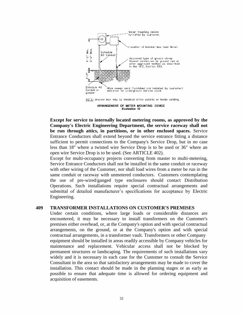
31
Except for service to internally located metering rooms, as approved by the
Company's Electric Engineering Department, the service raceway shall not
be run through attics, in partitions, or in other enclosed spaces. Service
Entrance Conductors shall extend beyond the service entrance fitting a distance
sufficient to permit connections to the Company's Service Drop, but in no case
less than 18" where a twisted wire Service Drop is to be used or 36" where an
open wire Service Drop is to be used. (See ARTICLE 402).
Except for multi-occupancy projects converting from master to multi-metering,
Service Entrance Conductors shall not be installed in the same conduit or raceway
with other wiring of the Customer, nor shall load wires from a meter be run in the
same conduit or raceway with unmetered conductors. Customers contemplating
the use of pre-wired/ganged type enclosures should contact Distribution
Operations. Such installations require special contractual arrangements and
submittal of detailed manufacturer’s specifications for acceptance by Electric
Engineering.
409 TRANSFORMER INSTALLATIONS ON CUSTOMER'S PREMISES
Under certain conditions, where large loads or considerable distances are
encountered, it may be necessary to install transformers on the Customer's
premises either overhead, or, at the Company's option and with special contractual
arrangements, on the ground, or at the Company's option and with special
contractual arrangements, in a transformer vault. Transformers or other Company
equipment should be installed in areas readily accessible by Company vehicles for
maintenance and replacement. Vehicular access shall not be blocked by
permanent structures or landscaping. The requirements of such installations vary
widely and it is necessary in each case for the Customer to consult the Service
Consultant in the area so that satisfactory arrangements may be made to cover the
installation. This contact should be made in the planning stages or as early as
possible to ensure that adequate time is allowed for ordering equipment and
acquisition of easements.

32
410 TEMPORARY INSTALLATIONS
Where service is required for construction or other temporary purposes, the
Customer shall provide a suitable location and anchorage for the Company's
Service Drop and Meter. Temporary service will be installed at the Customer's
expense. (See ARTICLE 422.2 for temporary Meter poles.) Temporary meter
poles may not be placed within the utility easement. Meter mounting devices
used in temporary installations shall be supplied by the Customer or his
Contractor and shall meet the requirements listed under Article 418.2.
UNDERGROUND SERVICE
411 COMMERCIAL UNDERGROUND:
Commercial Customers desiring Underground Service should contact the Service
Consultant in the area so that Electric Engineering may develop the Service
Specifications as required.
412 MOBILE HOME PARKS:
Customers desiring underground service to mobile home parks utilizing self-
contained Meter pedestals should contact the Company's Service Consultant so
that satisfactory arrangements can be made. Such installations generally require
additional contractual arrangements. The Company shall make all connections
between the Company's equipment, cables, or conductors and the Customer's
Service Entrance Conductors. Consult the Company's Service Consultant in the
area for charges for standby time of Company personnel during installation of
service conductors by electrical contractors into three-phase pad-mounted
transformers. Clearance near or around swimming pools shall adhere to the
requirements listed in Illustration 6 - Clearances of Wires, Conductors or Cables
installed around swimming areas, on page 26.
413 UNDERGROUND SERVICE LATERALS IN OVERHEAD AREAS
413.1 Requirements: It is necessary for Customers planning to install secondary
underground service in Overhead Distribution Areas to consult the Service
Consultant in the area to arrange for a Service Outlet Location and Data
Statement as set forth in Article 203 and obtain the necessary Service
Specifications for the installation. The Customer's underground riser conduit may
be installed on CenterPoint Energy-poles where the pole is located on Customer's
property or immediately adjacent in the street right-of-way or utility easement.
No more than four (4) conductors per phase and neutral shall be accepted per
metered service (no more than 16 conductors per pole total for all services).
Customer’s conduit installed on poles shall be only rigid metal, intermediate
metal, or PVC Schedule 80. When the underground service entrance conduit is

33
PVC and the riser on the pole is rigid or intermediate metal conduit, the Customer
or Customer’s contractor shall ground all risers in accordance with requirements
of the National Electrical Code.
Customer’s service riser may be installed on a service pole if located on the
Customer’s property. Service poles will be provided ONLY if the standard
service extension requires them. If service poles are not required for standard
service extension, the Customer shall install and maintain a separate pole for the
underground riser. The maximum conduit riser attached directly to a pole
shall not exceed one 3” conduit. Larger conduit and multiple conduits may be
installed on poles of sufficient strength, but they must be installed on stand-off
brackets (See Illustration 8 – Conduit risers on stand-off brackets, next page).
When the Company’s poles with approved customer equipment attached need to
be relocated or replaced, the customer is responsible for relocating all of their
equipment at their cost within 30 days of receipt of written notification.

34
413.2 Service Conduit: Customer may attach service conduit not larger than 3” inside
diameter directly to the Company's pole. Distribution Operations personnel will
specify on the Service Outlet Location when the Customer must attach the service
conduit directly to the pole, as in residential areas. Conduit risers shall be
permitted in order of service requests as shown by the Illustration 7 - Conduit
Risers Attached Directly to Pole, next page. In the event a primary riser is
attached to the pole, the primary riser shall be considered the #1 Customer, and
any further Customer service risers shall be installed on a stand-off bracket as #2,
#3, or #4 riser on the pole. In the case where two primary risers are attached to the
pole, no other conduit may be attached to the pole. See Illustration 7, next page.

35
Customers must use standoff brackets for service conduit larger than 3" inside
diameter. A maximum conduit size of 4" will be allowed. See Illustration 8 -
Conduit Risers on Stand-off Brackets, for suggested installation, page 34.
413.3 Service Riser Protection: Customer may not install theft deterrents that pose a
safety hazard to CNP personnel.

36
414 UNDERGROUND SERVICE IN UNDERGROUND
RESIDENTIAL AREAS
414.1 Since Underground Residential Distribution (URD) areas are established by
special contractual arrangements, special conditions for service may exist, and the
Customer must request URD Service Specifications through the Company's
Service Consultant in the area.
414.2 In the Underground Residential Distribution Area, the only type of service
available to each Customer shall be the type known as single-phase 120/240 volt,
three-wire, 60 hertz. This service is available to residential Customers only.
415 CUSTOMER INSTALLED UNDERGROUND CONDUCTORS
415.1 Requirements: In URD areas, the Customer or his Contractor shall furnish and
install the service conductors (Service Lateral) in accordance with Illustration 9 -
Arrangement of Residential Underground Equipment. The Company will make
all connections between the Customer's service conductors (Service Lateral) and
the Company's conductors and equipment.

37
NOTES: ARRANGEMENT OF RESIDENTIAL UNDERGROUND EQUIPMENT
1. Meter mounting device shall be furnished by the Customer and installed by
the Customer or Customer's electrical contractor. Location shall be on the side
of the house or garage where accessibility, height, working clearance, etc.
comply with Section 400 of the Service Standards.
2. Customer's contractor shall furnish and install service to the following
specifications:
A. Refer to ARTICLE 415 for conductor requirements.
B. Cable shall be installed a minimum of 2 ft. below grade if using direct
burial cable. Bottom of trench and backfill immediately above cable shall
be fine soil or sand, free of rocks, concrete, or hard objects which might

38
damage cable. Aluminum and aluminum alloy cables require the utmost
care in handling and installation, most installations are especially
susceptible to nicks and scratches, and careless handling may result in
failure of the cable.
3. Customer's contractor shall install service cable to within 1 ft. of secondary
service hole or transformer pad. (Contractor shall contact Distribution
Operations for proper location of service cable connections, if not apparently
evident on ground.) Service brought to transformer pads shall be left opposite
the small notched "V" mark on transformer pad. Ten (10) feet of service cable
shall be left for connection to a secondary pedestal or transformer. The cable
shall be coiled and secured to a stake as to be clear of the ground. Cut ends
shall be made watertight by an approved sealing method immediately after
cutting. Caution should be observed when digging within the area to avoid
damage to telephone, other cables, and gas pipe coatings. Damage to any
utility equipment shall be immediately reported to owner of utility.
CenterPoint Energy will not be responsible for damage by persons other than
its own personnel.
4. Temporary service poles shall be set outside the confines of the utility
easement.
5. For temporary services only, the height of the meter mounting device on
temporary meter poles in URD areas may be reduced below the requirements
of ARTICLE 420, but in no event shall the center line of the meter mounting
device be lower than 3 ft. above grade.
6. All services shall be properly grounded.
7. Breaker box may be installed either outside or inside building.
8. Construction in areas where electrical installations are governed by city
ordinance shall meet requirements of all applicable ordinances and codes.
9. The service entrance conduit may be schedule 40 or greater rigid non-metallic
conduit, electrical metallic tubing (EMT), rigid metal conduit, or intermediate
metal conduit except where subject to physical damage, such as near a parking
area, driveway, or gate. Only schedule 80 rigid non-metallic conduit, rigid
metal conduit or intermediate metal conduit may be used for the service
entrance conduit where subject to physical damage. (See Illustration 10-
Arrangement of Meter Mounting Device, page 31).
415.2 Service Conductors: Conductors shall be listed as “USE” rated and sized for load
according to the National Electrical Code latest edition and shall be clearly
marked as suitable for direct burial. Suitable conductor types are USE, THW,
THHW, TW, RHW, THWN, and XHHW. Direct buried conductors shall be
clearly marked as to type. Other conductor types require CenterPoint Energy
approval. Conductors must be installed with at least 24" of cover. The bottom of
the trench and backfill immediately above the conductors shall be of fine soil or
sand, free of any hard objects which could damage conductors. Conductors in
conduit shall be installed in accordance with the National Electrical Code latest
edition or as approved by the local governing authorities.

39
415.3 Conductors in Conduit: Conduit shall be buried in accordance with the National
Electrical Code latest edition, however, the conduit at the transformer or pedestal
end of the run shall have at least 24" of cover. Cables installed in conduit shall be
of types listed in ARTICLE 415.2. Service cables must be installed within 1 ft. of
the secondary pedestal or transformer pad as shown in the Illustration #11.
415.4 Installation: Service cables brought to transformer pads shall be left adjacent to
the small notch "V" in the transformer pad, (See Illustration 11) or adjacent to the
secondary pedestal. The cable shall be coiled and secured to a stake so as to be
clear of the ground. Cut ends must be made watertight by an approved sealing
method immediately after cutting. Caution should be observed when digging
within the area to avoid damage to other utility facilities. Damage to any utility
equipment must be reported immediately to the owner of such equipment. (See
Lone Star Notification Center, page 97).
415.5 Temporary Service (Underground): Temporary service for home construction
within the URD area will be available only at designated locations adjacent to
existing energized transformers or energized secondary cable junction boxes. The
applicant for temporary service or contractor must install a temporary meter pole.
Temporary meter poles may not be placed within the utility easement. A charge
will be made for the temporary service. Meter mounting devices used for
temporary service shall be supplied by the Customer or his Contractor and shall
meet the requirements listed under ARTICLE 418.2.

40
415.6 Swimming Pools: Underground conductors in the proximity of a swimming pool
or its auxiliary equipment must conform to the latest edition of National Electrical
Code. See Illustration 6 - Clearance of Wires, Conductors or Cables installed
around swimming areas, on page 26.
416 SERVICE TO APARTMENTS, TOWNHOMES OR CONDOMINIUMS
416.1 Requirements: The Company, by special contractual arrangements, will provide
underground service to apartment complexes. This service will be single-phase,
120/240 volt, 60 hertz and metered separately for each apartment unit. The
Company’s Service Consultant in the area should be contacted for contractual
information and Service Specifications for the part of the electrical services
facilities to be installed by the owner of the apartment complex.
416.2 Master-Metering: The apartment complexes that are served from master-metered
distribution system may be converted to individual unit metering, if re-wiring is
done to provide a separate electric service to each unit and special contractual
arrangements are made with the Company. Before making conversion plans the
owner should contact the Company’s Service Consultant in the area for the Terms
and Conditions for converting a master-metered system to a multi-metered
system.
416.3 Cable Terminal Boxes: Whenever more than four sets of Service Entrance
Conductors (maximum of 4 sets of 350 KCMIL conductors) are to be served from
a Company-owned pad-mounted transformer, services shall be supplied from a
cable terminal box. Customer's service equipment must be suitable for the
maximum fault current available or the Customer shall install current limiters.
Current limiters shall not be installed within pad-mounted transformers. The
Company will, upon request, furnish guidelines for the fabrication of a typical
cable terminal box. The use of a cable terminal box must be in accordance with
applicable codes and electrical ordinances. Cable terminal box typical details are
shown in Illustration 12 – Typical Cable Terminal Box Details, next page. All
cable terminal box fabricators shall be pre-approved. For approvals contact
Electric Engineering, Standards and Materials.

41
NOTES: TYPICAL CABLE TERMINAL BOX DETAIL
1. The above reflects general requirements and as such show typical details only.
Any equivalent designs submitted shall be considered.
2. Cable terminal box will be served by service lateral from CenterPoint Energy’s
transformer in CenterPoint Energy’s easement.
3. Cable terminal box and concrete foundation shall be owned, installed and
maintained by the owner. The location of the cable terminal box with respect to
the transformer will be by mutual agreement between CenterPoint Energy and the
contractor or owner.

42
4. Cable terminal box shall be made with two separate compartments; one side for
CenterPoint Energy connections and the other side for owner's connections. Doors
on both sides will be secured by a three point latch system.
5. CenterPoint Energy’s lock will be on CenterPoint Energy’s compartment of cable
terminal box.
6. The owner shall provide for locking the owner's compartment of the cable
terminal box. (Entire cable terminal box shall be tamper proof in accordance with
AMERICAN NATIONAL STANDARD ANSI C57.12.28 latest edition.
7. Fiberglass or other material shall not be acceptable.
8. Aluminum shall be used in all coastal areas such as Galveston and Freeport.
9. Cable terminal box shall be weathertight.
10. Cable terminal box shall be mounted and secured on concrete foundation in a
level position. Foundation to be capable of supporting junction box and
maintaining it in a level position.
11. The owner shall install conduit from CenterPoint Energy service lateral to cable
terminal box before CenterPoint Energy’s transformer and pad is installed.
12. Insulating barriers to be 1/2" thick and meet NEMA Code N-1, XX, GP01 or
GP03.
13. All bus bars shall be rigidly supported.
14. Bus bars shall not be formed inside the cable terminal box.
15. Each phase bus bar shall be a minimum of 1/4" X 4".
16. Aluminum bars shall be tin plated at connection points. Bus requirements of two
thousand Amps and above will consist of a tinned copper design.
17. The owner shall make provisions for 3 sets of 2-hole lugs per bus bar for
CenterPoint Energy’s side of cable terminal box.
18. The owner shall make provisions as required for the owner's requirements on
owner's side of cable terminal box.
19. The cable terminal box shall have sufficient mechanical strength and momentary
rating to withstand short circuit current given on outlet location statement.
20. CenterPoint Energy will connect facilities on its side of the cable terminal box.
The owner shall connect his on his side.
21. All cable terminal box fabricators shall be pre-approved. For approvals contact
Electric Engineering, Standards and Materials.
416.4 High-Rise Apartment/Multi-Unit Building: High-rise apartments or other
multi-unit high-rise complexes that are to be individually metered and served with
120/240 volt single-phase service, may allocate space within the building for
transformers if the total single-phase load exceeds 500 kVA. Additionally, the
Company may require that the Customer's wiring total single-phase load be
separated into two or three equal portions.
416.5 Meter Room Specifications: CNP prefers that meter rooms not be utilized, but if
meter rooms must be used they require approval by CNP Electric Engineering
prior to construction. Contact a CNP Service Consultant for the specification
necessary to address the installation of the advanced metering system (AMS) in
meter rooms for single story and multi-story buildings. AMS uses a wireless

43
communication system which must be incorporated into the design of the meter
room(s) to operate successfully.
CNP shall have 24/7 access to all locations where CNP meters are
installed. A key storage lockbox to open meter room doors is acceptable.
The key storage lockbox shall be easily accessible near the exterior door
closest to the lowest meter room.
For single story and multi-story buildings, where meters cannot be located
on an exterior wall, meter room(s) shall be located as close to an outside
perimeter wall as possible. All meter rooms in multi-story buildings shall
be built in the same relative location on each floor where a metering room
is required.
Modular Metering Units must be approved by CNP Personnel prior to
installation.
417 METER LOOPS
The Customer shall provide the necessary wiring for the Meter Loop with the
wire so arranged that the line (supply) side can be connected to the top terminals
of the meter mounting and the load side to the bottom terminals. All conductors
shall extend into the meter mounting device a minimum distance equal to the
length of the meter mounting device trough. If an aluminum neutral conductor is
used, it must be insulated. Where the service is three-phase, four-wire delta,
ground and phase wires shall be permanently identified in accordance with latest
edition of the National Electrical Code. The conductor serving power load (Hi-
Leg) shall be permanently identified or have a distinctive orange covering. The
Hi-Leg Conductor shall be connected to the far right meter socket terminal (while
facing the meter mounting device) on both the line and load sides. Meter
mounting device shall be furnished and installed by the Customer for all Self-
Contained installations. Only meter mounting devices which meet Company
specifications will be acceptable on the Company’s system. No Meter Loops
shall be allowed on Company poles.
418 METER INSTALLATIONS
Only CenterPoint Energy or its designated representative is authorized to install,
remove or relocate a meter. CenterPoint Energy reserves the right to discontinue
service to anyone violating this ruling.
418.1 Meters and Metering Equipment: The Customer shall furnish and own all self-
contained Meter Mounting Devices. Meter Mounting Devices shall be used for
both indoor and outdoor self-contained installations, and shall be furnished in
accordance with ARTICLE 418.2. Relocation and/or maintenance of the Meter
Mounting Devices will also be the responsibility of the Customer's Contractor.
All connections to the Meter Mounting Devices shall be made by the Customer's
contractor, except instrument transformer rated installations. All connections to

44
the Company's equipment shall be made by Company personnel only. Existing
three-phase residential Customers planning wiring changes shall contact the
nearest Company office before making changes.
METER CAN DECISION FLOW CHART
Illustration 12B
418.2 Meter Mounting Device: It shall be the responsibility of the Customer or his
Contractor to purchase the proper type of meter mounting device for residential or
commercial service in accordance with the Self Contained Meter Mounting
Device Chart, on this page. Meter mounting device shall be installed by the
Customer’s Contractor. The types of meter mounting devices are designed to
carry the continuous current as indicated for the several types of services shown.
Conductors installed in the Meter Mounting Devices shall be within the range of
approved sizes as listed on the UL labeling (lug sizes) within the Meter Mounting
Device or the Company will not install its Meters. The customer’s main service
breaker shall be sized for the meter mounting device used (i.e. up to a 200 amp
main for a 200 amp meter can and up to a 400 amp main for a 320 amp service).
In addition, for 320 Amp Meter Mounting Devices, the 320 Amp Specifications
on page 47 and 48 of these Service Standards also apply. The Customer will be
responsible for any damage to the Company’s metering devices, plus labor
charges to repair.
The conduit shall enter and leave the meter mounting device at location of
existing hubs or knockouts. The Customer or his Contractor shall close all unused

45
openings by means of galvanized metal plugs or hole closer. Line and load
conductors to the meter mounting device shall not be run in the same conduit.
SELF-CONTAINED METER DEVICE CHART
RESIDENTIAL SERVICE
TYPE OF SERVICE Meter Mounting Device
PHASE
WIRE VOLTAGE
(VOLT)
AMPACITY (AMP)
(Continuous Rating)
FIGURE
1 3 (Note 4) 120/208 200 2
1 3 120/240 125 or 200 1
1 3 120/240 320 See 320 Amp Illustration 13A&B, pg 47&48
3 4 (Note 2) 240/120 200 3
3 4 (Note 2) 240/120 320 See 320 Amp Illustration 13A&B, pg 47&48
COMMERCIAL SERVICE
TYPE OF SERVICE Meter Mounting Device
PHASE WIRE VOLTAGE (VOLT)
AMPACITY (AMP)
(Continuous Rating)
FIGURE
1 3 120/240 125 200, or 320 See 320 Amp Illustration 13A&B, pg 47&48
1 3 (Note 4) 120/208 200 2
3 4 240/120 200 or 320 See 320 Amp Illustration 13A&B, pg 47&48
3 4 208/120 200 or 320 See 320 Amp Illustration 13A&B, pg 47&48
3 4 480/277 200 or 320 See 320 Amp Illustration 13A&B, pg 47&48
3 3 (Note 1, 3) 480 200 or 320 See 320 Amp Illustration 13A&B, pg 47&48
Notes:
(1) Requires a bonding conductor, Article 303.
(2) Three-phase residential services are not generally
available. Article 303.
(3) Fifth terminal lug shall be isolated from the can.
(4) Fifth terminal lug shall be bonded to the service neutral conductor.
Service provided for Underground Street Network only (See Article 301)
46
Meter Mounting Device General Specifications
All materials, construction, and testing shall be in accordance with the American National
Standards Institute (ANSI) C12.7, Requirements for Watthour Meter Sockets, latest
revision.
The meter socket housing shall be fabricated of steel, or aluminum in accordance with U/L
Standard 414, latest revision and be suitable for outdoor use in accordance with NEMA 3R,
latest revision.
All meter cans shall be painted after fabrication and finish coats shall provide a tough non-
chalking weather resistant finish.
Performance requirements for meter sockets shall be in accordance with applicable
performance sections of ANSI C12.7 and UL-414 (latest revisions).
Meter socket shall be tested in a certified test lab to meet Underwriters Laboratory (U/L)
Standard 414, latest revision, performance requirements and labeled as such.
Socket jaws shall be rated for 600 volts.
Five terminal cans shall have the fifth terminal located in the 9 o’clock position.
Fifth terminal lug shall be isolated from the can.
Knockouts shall not be above any energized surfaces with the meter in place.
Minimum inside dimensions of the enclosure shall be sufficient to provide ample room for
the distribution of the maximum-size conductors for which the socket is intended. Internal
wiring space shall be such as to allow line or load conductors, or both, entering either or
both ends of the enclosure to be readily routed to the proper terminals.
Meter socket installation shall be in accordance with CenterPoint Energy Service Standards,
latest revision and meet any code requirements that may be enforced by the local Public
Authority.
Maintenance on all Customer owned devices is the responsibility of the Customer.
125 Amp and 200 Amp Meter Mounting Device
Socket jaws shall be rated for 125 amp or 200 amp continuous current capability.
Meter socket bypass devices are not allowed.
All meter sockets will be ring type. Meter sockets with ringless covers will not be allowed.
All single-phase four terminal 125Amp and 200 Amp cans shall have tamper proof lids (TP
Bar construction).

47
320 Amp Meter Mounting Device
Socket jaws shall be rated for continuous current capability.
Meter sockets shall be offset or side wireway models. Exception - 3-Phase, 3-Wire meter
sockets.
(See illustrations # 13A and 13B page 47 & 48)
Terminal jaws shall be equipped with a by-pass feature operable by use of a lever that
controls the clamping of the meter blades (Jaw release) and allows for current by-pass when
the need for meter removal is required. By-pass current capacity shall be 320 amperes
continuous. Horn-type, sliding-type and automatic bypasses are not permitted.
The socket shall be capable of utilizing mechanical or compression lug connectors (3/8” or
1/2” studs) for the following conductor sizes and maintain U/L standards for wire bending
radius requirements.
Single Conductors: (Note: Wire sizes over 500 KCMIL will
4/0 – 500KCMIL (Single Lug Assembly) require CT Rated meter installation)
Parallel Conductors:
1/0 – 250KCMIL (Twin Lug Assembly)
Terminals shall be 3/8” or 1/2” cold headed zinc plated steel studs to accommodate
mechanical or compression lugs. The studs shall be attached to tin-plated mounting plates
compatible with aluminum or copper lugs.
All meter sockets shall have an insulated protective safety shield.
The meter can lid shall have a ringless meter opening only, with a latch and sealing/locking
provision. No screws are allowed on meter can lids.
The cover (lid) of the meter socket shall be such that it cannot be placed over the meter with
the bypass lever in the bypassed position and must be tamper resistant.

48
418.3 Self-Contained Meter Pedestals: Self-contained meter pedestals are to be used
only in mobile home parks served from underground facilities and for power
supply metering of Cable TV (CATV) installations. Where used, self-contained
meter pedestals SHALL BE FURNISHED, INSTALLED AND
MAINTAINED BY THE CUSTOMER after contractual arrangements (See
ARTICLE 412) for the installation of underground facilities have been completed.
The pedestals shall meet the following minimum requirements. The meter
mounting device shall have an ampacity of 200 amps for mobile home park
applications and an ampacity of not less than 50 amps for CATV power supply
applications. At the pedestal, an adequate disconnecting means shall be provided
for each service on the load side of the meter. The ground rod connection shall be
made at ground level for easy access. The neutral conductor shall come into the
pedestal at least to the switch box ground terminal. The pedestal shall extend not
less than 30" below final grade. If required, adequate stabilization material shall
be added to ensure that the pedestal will remain vertical at all times. Customers
contemplating the use of self-contained meter pedestals should submit detailed
manufacturer’s specifications for acceptance by Electric Engineering.

49
418.4 Pre-Wired Modular/Ganged Type Meter Banks: Pre-wired modular/ganged
type meter banks may be utilized under certain conditions. CUSTOMERS
CONTEMPLATING THE USE OF PRE-WIRED/GANGED TYPE
ENCLOSURES SHOULD CONTACT DISTRIBUTION OPERATIONS.
SUCH INSTALLATIONS REQUIRE SPECIAL CONTRACTUAL
ARRANGEMENTS AND SUBMITTAL OF DETAILED
MANUFACTURER'S SPECIFICATIONS FOR ACCEPTANCE BY
ELECTRIC ENGINEERING.
419 METHODS OF INSTALLING METER MOUNTING DEVICES
419.1 Requirements: Meter mounting devices shall not be used as junction boxes for
the Customer's wiring. Customer’s wiring shall be installed in Meter Mounting
Devices, as follows:
419.1.1 Meter Mounting Devices for Socket Type Meters rated at 200
amperes or less: Only one conduit and one set of Service Entrance Conductors
shall be used on the line side, and one conduit and one set of Service Entrance
Conductors shall be used on the load side of meter mounting device.
419.1.2 Meter Mounting Devices for Self-Contained Meters rated at more
than 200 amperes: Meter mounting devices rated at greater than 200 amperes
shall not be used where the anticipated load and service entrance conductors have
a rating of 200 amperes or less. No more than two conduits and two sets of
Service Entrance Conductors shall be used on the line side and no more than two
conduits and two sets of Service Entrance Conductors shall be used on the load
side of the meter mounting device. The conductors do not have to be the same
size for line and load. The Customer or Customer’s contractor shall make all
connections to the Meter Mounting Device, except for instrument transformer
rated installations. (For more information on 320 Amp meter mounting devices,
see ARTICLE 418.2 and Illustration 13A & 13B on previous page.
419.2 Meter Mounting Device
Multiple occupancy service usually requires that Service Entrance Conductors be
in a sealable weatherproof wiring trough similar to the arrangements shown for
single-phase installations in Illustration 15 - Multiple Installation Using Wiring
Gutter and Individual Meter Mounting Devices, next page. Line taps shall be
made in the wiring trough by the electrical contractor. No more than four (4)
weatherheads and four (4) conductors per phase and neutral shall be allowed
in a wiring gutter installation. Pre-wired/ganged type installations shall be
limited to one (1) weatherhead and one (1) conductor per phase and neutral.
Accepted grounding practices for multi-meter installation are shown in
Illustration 16 - Acceptable grounding practices for multi-metering installations,
on page 51.

50

51
419.3 Meter Mounting: Meter Mounting Devices shall be installed so that the display
of the meter is level.
419.4 Clearances: Meter Mounting Devices shall be installed by the Customer or the
Customer’s Contractor with a free space of at least 36" in front and 2" on the
sides, top and bottom, as necessary clearance to install, remove, and to test
equipment. The free space shall be over the Customer's property or public ways
and shall not encroach upon the property of others even though there may be a
utility easement in the area of encroachment.
419.5 Service Cable Tap Box – Multi-Tenant Services: In Multiple-Tenant buildings
where additional services are likely, a bus conductor service cable tap box may be
required similar to Illustration 33A, next page. A Multiple occupancy service
usually requires that Service Entrance Conductors be in a sealable weather-tight
wiring tap box similar to Illustration 33B. Line taps shall be made in the tap box
by the electrical contractor. Accepted grounding practices for multi-meter
installations are shown in Illustration 16. All Service Cable Tap Box
Fabricators shall be pre-approved. For approvals, contact Electric Engineering
Standards & Material.

52

53
NOTES: TYPICAL SERVICE CABLE TAP BOX DETAILS
1. The above reflects general requirements and as such show typical details only.
Any equivalent designs submitted shall be considered.
2. Service Cable Tap Box will be served by service entrance conductors from
CenterPoint Energy’s transformer or customer’s weather-head.
3. Service Cable Tap Box and conductors shall be owned, installed and maintained
by the owner.
4. Service Cable Tap Box shall be lockable and can accept a CenterPoint Energy
lock.
5. Covers shall be fastened with machine screws or bolts. Hinged covers shall not be
permitted.
6. Covers shall have two handles for cover removal.
7. Non-Metallic material such as fiberglass shall not be acceptable.
8. Service Cable Tap Box shall be weather-tight and fabricated from minimum
12GA Steel or equivalent metal.
9. The bottom of Service Cable Tap Box shall be a minimum of 6” above finished
grade.
10. 600V Insulators are required for supporting the energized bus bar.
11. Bus bars shall be sized to physically accommodate the maximum number of
tenant services anticipated and predrilled for conductor tie-ins.
12. All bus bars shall be rigidly supported and protected from physical damage.
13. The phase arrangement on three phase horizontal common power and vertical
buses shall be A-B-C from front to back, top to bottom, or left to right as viewed
from the front of the Service Cable Tap Box. B phase shall be that phase having
the higher voltage to ground on three phase, 4-wire, Delta connected systems. The
phases shall be permanently marked.
14. The bus arrangement shall include 2-hole NEMA spaced holes for cable
termination.
15. Service Cable Tap Box shall have sufficient mechanical strength and momentary
rating to withstand short circuit current given on outlet location statement.
16. All Service Cable Tap Box fabricators shall be pre-approved. For approvals,
contact CNP Electric Engineering, Standards and Materials.
17. For use on service voltages through 480V.
Exception: Residential Occupancies
420 HEIGHT OF METERS
420.1 Socket Bases: The height of meter mounting devices shall be such that the center
of the opening for the meter is between 4 ft. and 6 ft. above ground or floor level.
The meter mounting devices may be mounted at a height greater than 6 ft. above
ground where required due to local building codes which establish minimum
building elevations for flood protection. Contact the Service Consultant in the
area in cases where flood plain construction occurs. The meter mounting devices

54
may be mounted on a stairway and must be mounted so as to provide easy access
to read the meter.
420.2 Pedestals: The height of self-contained meter pedestals used in mobile home
parks shall be such that the center of the opening for the meter is between 3 ft. and
6 ft. above ground level.
421 METER LOCATION
421.1 All metering equipment shall be installed on the supply side of the main switch.
No Customer-owned device(s) shall be allowed ahead of the meter except those
required by the Company. (See ARTICLE 423)
421.2 All residential and combination residential and commercial service meters shall
be installed outdoors. In residential areas where service is supplied underground,
the meter shall be located on the side of the house instead of the rear of the house.
(See Illustration 9, on page 37) In residential areas where service is supplied
overhead and the house is accessible to overhead service drops to a rear
corner, the meter shall be located on the side of the house instead of the rear.
In all cases the meter shall be located in a position that is accessible to
Company employees at all times without Customer assistance. Access to the
meter shall not be blocked by locked gates, walls or fences without prior
approval by the CNP Primary Metering Manager.
421.3 Meters are to be installed immediately above or below line gutter except for
480Y/277 volt service or 480 volt service, in which case the required meter
disconnect will be between the line gutter and the meter and shall be located so
the height of the operating handle is not less than 4 feet and not more than 7 feet
above finish grade. (See Article 423) Also, a minimum 4” clearance should be
provided to the right of the meter disconnect to allow adequate clearance for
locking.
421.4 Meters shall not be located where they will interfere with traffic on sidewalks or
driveways, or where they will obstruct the opening of doors or windows.
421.5 Metering equipment shall be installed on a wall which is a substantial part of the
building itself or on a meter pole. Temporary partitions, etc., which are subject to
replacement or excessive vibration shall not be used. Meters or metering
equipment shall not be installed on the Company's poles.
421.6 Grouping: Where more than one meter is installed, the meters shall be grouped at
a point accessible at all times to the Customer's and Company employees. EACH
METER MOUNTING DEVICE SHALL BE CLEARLY AND
PERMANENTLY MARKED ON THE OUTSIDE TO SHOW THE
APARTMENT AND/OR ADDRESS TO BE SERVED BY THE METER. It
shall be the responsibility of the Customer or his Contractor to ensure the

55
accuracy of the markings with respect to the apartment and/or address. For
changes in existing wiring, the Customer should consult the Service Consultant.
421.7 Wiring Gutter: On apartment buildings which are served 120/240, 120/208 volts,
single phase, the wiring trough with individual meter mounting devices in
Illustration 15 on page 50 may be used. Where space limitations will not permit
placing all meter mounting devices on the same level, the meter installation may
be made by arranging them in two tiers. The center of the opening for the meters
in the lower tier shall not be less than 2.5 ft. above finished grade-level and the
center of the opening for the meters in the upper tier shall not be more than 6.5 ft
above finished grade level. The center of the meter opening for a "building
service" or any meter mounting devices requiring a kVA demand-type meter shall
not be greater than 6 ft above finished grade-level. Where space limitations will
not permit placing meter mounting devices as outlined above, or if the installation
involves multiple three-phase installations and they cannot be arranged at the
same height, consult the Company's Service Consultant or the nearest Company
Office listed on page 4.
422 METER POLE INSTALLATIONS
422.1 Requirements: A meter pole is required in those cases where suitable location,
clearance, and anchorage as called for in Articles 403, 404 and 406 are not
available on the Customer's premises. Even if the conditions set forth in Articles
403, 404 and 406 are satisfied, the Customer has the option to install a meter pole.
Meter poles shall not be installed in utility easements. The use of alternate types
of meter poles must have Company approval before installation. The meter pole,
whether required or at the Customer's option, shall be a round pole or a 4" X 6" or
6" X 6", timber pressure treated with penta or creosote, and installed and
maintained by the Customer at his expense. All meter poles shall provide the
point of attachment, clearances, and anchorage as described herein. The pole
setting depth shall be a minimum of 4 ft., or 2 ft. plus 10% of the pole length,
whichever is greater.
422.2 Temporary Service: Meter poles for temporary service of 125 Amperes or less
may be 4" X 4", or larger, timber if well anchored and braced to withstand the
strain of the Service Drops. Such meter poles may be used only when the
Company's Service Drops will not cross a street or roadway. When the Company's
Service Drops must cross a street or roadway, the Customer may pay the
Company for the cost of installation and removal of a service pole. As an
alternative, the Customer may install a 30 ft., round creosoted meter pole (25 ft.
above ground) on his property and within 70 ft. of the Company's pole so that
proper road clearance of the Service Drops may be maintained. Temporary meter
poles may not be installed in utility easements. Meter Mounting Devices used for
temporary single phase service (T-Saw) installations shall be supplied by the
Customer or his Contractor and shall meet the requirements shown in Article
418.2.
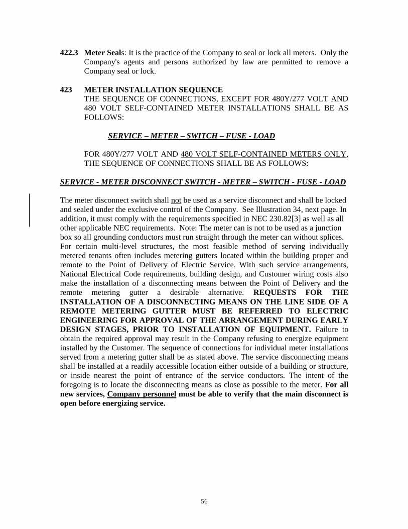
56
422.3 Meter Seals: It is the practice of the Company to seal or lock all meters. Only the
Company's agents and persons authorized by law are permitted to remove a
Company seal or lock.
423 METER INSTALLATION SEQUENCE
THE SEQUENCE OF CONNECTIONS, EXCEPT FOR 480Y/277 VOLT AND
480 VOLT SELF-CONTAINED METER INSTALLATIONS SHALL BE AS
FOLLOWS:
SERVICE – METER – SWITCH – FUSE - LOAD
FOR 480Y/277 VOLT AND 480 VOLT SELF-CONTAINED METERS ONLY,
THE SEQUENCE OF CONNECTIONS SHALL BE AS FOLLOWS:
SERVICE - METER DISCONNECT SWITCH - METER – SWITCH - FUSE - LOAD
The meter disconnect switch shall not be used as a service disconnect and shall be locked
and sealed under the exclusive control of the Company. See Illustration 34, next page. In
addition, it must comply with the requirements specified in NEC 230.82[3] as well as all
other applicable NEC requirements. Note: The meter can is not to be used as a junction
box so all grounding conductors must run straight through the meter can without splices.
For certain multi-level structures, the most feasible method of serving individually
metered tenants often includes metering gutters located within the building proper and
remote to the Point of Delivery of Electric Service. With such service arrangements,
National Electrical Code requirements, building design, and Customer wiring costs also
make the installation of a disconnecting means between the Point of Delivery and the
remote metering gutter a desirable alternative. REQUESTS FOR THE
INSTALLATION OF A DISCONNECTING MEANS ON THE LINE SIDE OF A
REMOTE METERING GUTTER MUST BE REFERRED TO ELECTRIC
ENGINEERING FOR APPROVAL OF THE ARRANGEMENT DURING EARLY
DESIGN STAGES, PRIOR TO INSTALLATION OF EQUIPMENT. Failure to
obtain the required approval may result in the Company refusing to energize equipment
installed by the Customer. The sequence of connections for individual meter installations
served from a metering gutter shall be as stated above. The service disconnecting means
shall be installed at a readily accessible location either outside of a building or structure,
or inside nearest the point of entrance of the service conductors. The intent of the
foregoing is to locate the disconnecting means as close as possible to the meter. For all
new services, Company personnel must be able to verify that the main disconnect is
open before energizing service.

57

58
NOTES:
Service Entrance Conductors: (See Articles 402.1 and 408.) Phase conductors for
permanent installations must not be smaller than #6 CU or #4 AL, unless approved by the
Company.
Service Entrance Raceway: (See Article 408.)
Meter Mounting Device: Meter Mounting Device is to be furnished and installed by the
Customer. (See Article 418.2 of CenterPoint Energy Service Standards for correct size of
meter mounting device)
Service Entrance Disconnect and Overcurrent Protection: Externally and manually
operable with overcurrent protection (fusing or breaker setting) not greater than capacity
of service entrance conductors; May be located inside or outside of building; Must be
rain tight if mounted outdoors, either on a building or on a pole.
Grounding Electrode Conductor: The grounding electrode conductor shall be
continuous without splices from the neutral bus in the service equipment to the grounding
electrode. The grounding electrode conductor, minimum size #8, or its enclosure shall be
securely fastened to the surface on which it is carried. A #4, or larger, conductor may be
exposed but shall be protected if exposed to severe physical damage. A #6 grounding
conductor that is free from exposure to physical damage shall be permitted to be run
along the surface of the building construction without metal covering or protection where
it is rigidly stapled to the construction; otherwise, it shall be in conduit, electrical metallic
tubing, or cable armor. Grounding conductors smaller than #6 shall be in conduit,
electrical metallic tubing, or cable armor. The National Electrical Code requires
grounding to a "Grounding Electrode." A driven ground rod is preferred by CenterPoint
Energy.
Bonding (Jumper) Conductor: A reliable conductor to ensure the required electrical
conductivity between metal parts required to be electrically connected. A bonding
conductor (jumper) shall not be installed on the meter socket neutral lug. The bonding
conductor should be attached to the meter can via the meter can’s bonding lug or other
acceptable method of attachment to the meter can’s metal surface. See Illustration 4.

59
SECTION 500 – LARGE COMMERCIAL INSTRUMENT TRANSFORMER
RATED METER SERVICE INSTALLATIONS
500 GENERAL INFORMATION
The Customer’s wiring installation should conform to the requirements of
the National Electrical Code and the National Electrical Safety Code, State,
Municipal requirements in force at the time the installation is made and the
Company Service Standards as to Service Outlet Location, Service Drop,
Meter Location and height, etc. Compliance with all such codes and
requirements is the sole responsibility of the Customer for all Customer
wiring and equipment. The Company does not inspect Customer wiring and
equipment, and the supplying of Electric Service by the Company does not
mean that Customer wiring and equipment has been inspected or approved
by the Company. General requirements detailed in Section 200 governing
service installations are available from the Company’s Service Consultants in the
area. Large Service Customers should contact the appropriate key Accounts
Representative in the planning stages or as early as possible to ensure
adequate time is allowed for the preparation of individual specifications,
ordering equipment and acquiring easements, if required.
500.1 Motor Starting Currents
Motors generally require a starting current substantially greater than their normal
running current. An abnormal drop in supply voltage results when starting
currents are excessive. It is essential that the Customer’s motors not exceed
allowable starting characteristics to minimize detrimental effects upon equipment.
Contact the Service Consultants upon adding any new motor load of 250
horsepower or more. DC and Adjustable Speed Drive motors generate harmonic
currents that may severely distort the customer’s voltage, and could effect service
to other CenterPoint Energy customers. Therefore, before installing DC or
Adjustable Speed Drive motors totaling over 250 hp, please submit to the Service
Consultants each harmonic current, in percent of fundamental 60 Hertz frequency,
generated by the motor. Where harmonic currents at CenterPoint Energy’s meter
exceed IEEE Standard 519 limits, the customer will be required to filter the
disruptive frequencies. Before placing orders for motor control equipment,
Customers contemplating the installation of large motors shall consult the nearest
Company Office (See page 4) to ascertain the allowable motor starting currents at
the specified location. Customers wanting to operate a group of motors from a
single control shall consult with the Company to ascertain the allowable motor
starting currents at the specified location.

60
500.2 Loads Having Abnormal Electric Characteristics Certain types of equipment have electrical characteristics which may cause
serious fluctuations of voltage and interfere with the service of the Company to its
Customers. In such cases the Company shall decline to serve such equipment
under the Company’s established Rate Schedules until the Customer, at his
expense, has provided suitable apparatus to hold the effects of such fluctuations
within reasonable limits. Circumstances may require such equipment to be
supplied from a separate service and, in such event, the Company may require
additional contractual arrangements and may meter such services separately from
other services supplied to the Customer.
Installation of X-ray equipment may require special equipment on the part of both
the Customer and the Company. The Company shall be consulted before any
special wiring is started for X-ray equipment.
An increasing segment of Customer load today incorporates electronic
components and can cause harmonic distortion in the Customer’s voltage and
current. This distortion can cause negative effects in the Customer’s operations
and can affect the service to other CenterPoint Energy Customers. For this
reason, CenterPoint Energy requires limits to harmonic distortion in compliance
with IEEE Standard 519 and in accordance with CenterPoint Energy
Specification 007-231-83 to insure proper service to all Customers. The
following are examples of harmonic producing equipment devices.
DC or variable frequency AC motors utilized in air conditioning chillers and
blower motors, pump motors and plastic extrusion, etc.
Electronic equipment such as computers and microprocessor controls.
Equipment utilizing arcing devices including:
-Arc furnaces
-Welders, and
-Florescent, sodium and mercury vapor lighting with high-efficiency
electronic ballast controlled lighting.
Power factor correction capacitors can magnify harmonic distortion. Before
installing any of the equipment discussed above or other similar devices
including power factor correction capacitors, contact the Service Consultant
for guidance to ensure the proposed loads will not exceed CenterPoint
Energy’s or IEEE Standard 519 limits.
500.3 Ranges, Ovens And Other Heating Devices
Large heating devices to be operated from 3-wire or 4-wire service shall have the
elements connected so that the load is evenly divided between the wires, or
phases, when such equipment is equipped with automatic control that may cause
frequent connection and disconnection of the load. The Customer shall consult
with the Company concerning the allowable variation in load. The Customer
61
shall consult with the nearest Company office and determine the exact type of
service to be supplied before placing orders for heating equipment other than the
portable or plug-in type.
500.4 Heavy Duty Portable Equipment Contractors, builders and others contemplating the temporary use of heavy-duty
portable equipment such as floor sanders, welders, tile polishers, etc., are required
to apply to the nearest Company Office and make satisfactory arrangements
before connecting any such equipment to convenience out-lets or other light-duty
circuits. In cases of non-compliance with this regulation, they will be held liable
for any damage to the Company’s service facilities.
500.5 Customer Owned Generating Equipment
Before Customer-owned generating equipment may be interconnected to the
Company system, application must be made and approved. (See CenterPoint
Energy Specification 007-231-76.) For more information, contact the Service
Consultant at the nearest Company Office. (See Article 215 page 17).
500.6 Fire Pumps
Fire Pump Services shall be served through a C.T. Metered Service. (See
Instrument Transformer Rated Meter Installation Sequence, Article 517 and
Metering C.T. Box, Article 513.5).
501 SERVICES
The Company will supply to a Customer, at each Point of Delivery, only one
of the Types of Service listed in these Service Standards. The Customer’s
installation is to be so arranged that the Company can measure the power
used by the Customer with one meter.
OVERHEAD SERVICE
502 SERVICE DROP
502.1 Requirements: The Company will install one Service Drop from the Company’s
distribution Lines to the Customer’s Service Outlet. Open wire type Service
Drop, which requires a seven point rack (see Illustration 17), must be used for 480
volt, 3 wire delta service (See Illustration 17 - Typical Commercial Open Wire
Service Installation, page 62). Twist conductor is allowed only for 277/480v, 4
wire service and 240/480v, 3 wire single phase (governmental entities for lighting
only). Where Service Outlets are grouped (See ARTICLE 505), the combined
ampacity of all Service Outlets shall determine the type of Service Drop. (See
Illustration 18 – Arrangement of Overhead Commercial Service Equipment, page
63.)

62

63
502.2 Service Drop Length
The maximum length of Service Drop which the Company installs will be
governed by the amount and Type of Service and will be determined by Company
personnel. Allowable voltage drop and mechanical factors, determined by the
size and number of wires of Service Drop, impose limits on its length.

64
502.3 Service Poles
Where a service pole or poles must be set to provide proper clearance around or
over driveways, garages, trees, or other obstructions on the premises, a charge
shall be made for each such service pole required.
503 CLEARANCE FOR SERVICE DROP
503.1 Service Drop Conductors, when not in excess of 600 volts, shall at least have the
minimum clearances at the lowest point of the drip loop or service drop listed in
Illustration 20 – Clearances for Service Drop.

65
503.2 If an existing service is being modified and any revision in the service entrance
raceway is made, the modified service must conform to the heights and clearances
outlined above.
503.3 Located no closer than 5 ft. to windows, doors or porches from which the Service
Drop may be accessible. This clearance is an NESC requirement and must be
maintained.
503.4 Service Drops must be free of contact with trees. The customer shall trim all trees
required to provide the necessary clearances.
503.5 Under no circumstances will the Company attach its Service drop to an
intermediate structure installed by the Customer between the Company’s
Distribution Lines and the Customer’s Service Outlet.
504 LOCATION OF SERVICE OUTLET
504.1 The location must be at a sufficient height above ground level to provide proper
clearances for the Service Drop, as required by ARTICLE 503. For the open wire
type Service Drop, the Service Outlet shall not be less than 6” no more than 18”
horizontally and not less than 6” nor more than 12” above the Point of
Attachment. (See Illustration 17 – Typical Commercial Open Wire Service
Installation, on page 62).
504.2 Service Outlet shall be located so that neither the Company’s Service Drop nor
the Customer’s Service Entrance Conductors are nearer than 12” to any telephone
or signal wires, whether in the air or on the building.
505 GROUPING OF SERVICE OUTLETS If a building has an established Service Outlet location which conforms to the
above requirements, then any additional Service Outlets shall be located within
18” of this established point. NO MORE THAN SIX WEATHERHEADS
SHALL BE INSTALLED AT EACH SERVICE OUTLET LOCATION. If
the established location does not conform to these requirements, then all Service
Outlets shall be combined at a satisfactory point specified by the Company.
When the total cross-sectional area of all Service Entrance Conductors at a service
outlet location exceed 2-1000 KCMIL per phase, a bus bar type weatherhead must
be used. (See Illustration 18 – Arrangement of Overhead Commercial Service
Equipment, on page 63).

66
506 POINT(S) OF ATTACHMENT
506.1 Provisions: A solid Point of Attachment for supporting the Service Drop on the
building shall be provided by the Customer at a point which will comply with the
provisions of ARTICLES 503 and 505. The Point of Attachment shall not be
more than 25 feet above ground. (See Illustration 20, on page 64). Company
personnel will specify on the Service Outlet Location, the height of the Point of
Attachment if it must be less than the minimum or greater than 25 ft. above grade.
506.2 Clearances: Where the required heights and clearances specified above cannot
be maintained, the Customer shall provide an extension support, which is of a
permanent nature and of sufficient strength to support the Service Drop at the
required minimum clearance. In such cases, the Customer’s Service Outlet is to
be located above the service support at a height which will permit the required
clearance. If a Service Mast will not have sufficient strength to properly support
the Service Drop, installation of a service bracket will be required.
507 ANCHORAGE FOR SERVICE DROP
507.1 Installation: The Customer shall install the Service Drop support in accordance
with ARTICLE 506.2. The type of Service Drop (open wire) to be installed shall
be determined in accordance with ARTICLE 502. The service drop support must
be installed as securely as possible to minimize damage to the installation from
storms, falling branches, or other hazards.
507.2 Open Wire Drop: For an open wire Service Drop the Customer shall install a
secondary rack fastened to his structure with two 5/8” galvanized machine bolts
of sufficient length for the threaded end of the bolt to extend 2” beyond the
surface of the wall and so installed that each bolt will be capable of withstanding
a pull of 300 lbs. The bolts shall be installed vertically 16” apart with the bottom
bolt not less than 12’-0” nor higher than 23’-4” above ground level. When
required ground clearance cannot be obtained otherwise, the Customer’s
Contractor shall secure written permission from the company to install the bolts
horizontally with the same spacing as for vertical installation. The company will
supply the bolts and rack when requested by the customer. When the service
entrance phase conductors exceed 2-500 KCMIL per phase, the Service Drop
anchorage arrangements shall be in accordance with the Illustration 26 –
Weatherhead Arrangement for Outdoor Metering, page 67.

67

68
508 SERVICE ENTRANCE CONDUCTORS The Service entrance Conductors, as defined in ARTICLE 127, shall be installed
in rigid metal conduit, intermediate metal conduit, electrical metallic tubing,
Schedule 80 PVC conduit, or, as permitted by the local governing authority, may
be an approved service entrance cable. The Service Entrance Conductors shall be
provided with a weatherproof entrance fitting where they extend from the
Customer’s conduit or raceway.
Except for service to internally located metering rooms, as approved by the
Company’s Electric Engineering Department, the service raceway shall not
be run through attics, in partitions, or in other enclosed spaces. Service
Entrance Conductors shall extend beyond the service entrance fitting a distance
sufficient to permit connection to the Company’s Service Drop, or 36” where an
open wire Service Drop is to be used. (See Article 502.1.)
Except for multi-occupancy projects converting from master to multi-metering,
Service Entrance Conductors shall not be installed in the same conduit or raceway
with other wiring of the Customer, nor shall load wires from a meter be run in the
same conduit or raceway with unmetered conductors. Customers contemplating
the use of pre-wired/ganged type enclosures should contact Distribution
Operations. Such installations require special contractual arrangements and
submittal of detailed manufacturer’s specifications for acceptance by Electric
Engineering.
509 TRANSFORMER INSTALLATIONS ON CUSTOMER’S PREMISES
Under certain conditions, where large loads or considerable distances are
encountered, it may be necessary to install transformers on the Customer’s
premises either overhead, or, at the Company’s options and with special
contractual arrangements, on the ground, or at the Company’s options and with
special contractual arrangements, in a transformer vault. See Article 512 for
primary underground service in Overhead Areas.
Transformers or other company equipment shall be installed in areas readily
accessible by company vehicles for maintenance and replacement. Vehicular
access shall not be blocked by permanent structures or landscaping. The
requirements of such installations vary widely and it is necessary in each case for
the Customer to consult the Company’s Service Consultant in the area so that
satisfactory arrangements may be made to cover the installation. This contact
should be made as early as possible to ensure that adequate time is allowed for
ordering equipment and acquisition of easements.
510 TEMPORARY INSTALLATIONS
Where service is required for construction or other temporary purposes, the
Customer shall provide a suitable location and anchorage for the Company’s
Service Drop and Meter. Temporary service will be installed at the Customer’s
expense.

69
UNDERGROUND SERVICE
511 COMMERCIAL UNDERGROUND
Commercial Customers desiring Underground Service should contact the Service
Consultant in the area so that Electric Engineering may develop the Service
Specifications as required. The Company shall make all connections between the
Company’s equipment, cables, or conductors and the Customer’s Service
Entrance Conductors. Consult the Company’s Service Consultant in the area for
charges for standby time of Company personnel during installation of service
conductors by electrical contractors into three-phase pad-mounted transformers.
512 UNDERGROUND SERVICE LATERALS IN OVERHEAD AREAS
512.1 Requirements: It is necessary for Customers planning to install Secondary
Underground Service in Overhead Distribution Areas to consult the Service
Consultant in the area to arrange for a Service Outlet Location and Data
Statement as set forth in ARTICLE 203 and obtain the necessary Service
Specifications for the installation. The Customer’s Underground riser conduit
may be installed on CenterPoint Energy poles where the poles are located on
Customer’s property or immediately adjacent in the street right-of-way or utility
easement. Customer’s service riser may be installed on a service pole if located
on the Customer’s property. Service poles will be provided ONLY if the standard
service extension requires them. If service poles are not required for standard
service extension, the Customer shall install and maintain a separate pole for the
underground riser. The maximum riser conduit attached directly to a service
pole shall not exceed one 3” conduit. Larger conduit and multiple conduits may
be installed on poles of sufficient strength, but they must be installed on stand-off
brackets (See Illustration 23 – Conduit Riser on Stand-off Brackets, next page).

70
No more than four (4) conductors per phase and neutral shall be accepted per
metered service (no more than 16 conductors per pole total for all services). (See
ARTICLE 513.5 for limitation of conductors inside a metering current
transformer box.) Customers’ conduit installed on poles shall be only rigid metal,
intermediate metal, or PVC Schedule 80. When the underground service entrance
conduit is PVC and the riser on the pole is rigid or intermediate metal conduit, the
Customer or Customer’s contractor shall ground the riser in accordance with the
National Electrical Code.
512.2 Service Conduit: Customer may attach service conduit not larger than 3”
inside diameter directly to the Company’s pole. Distribution Operations
personnel will specify on the Service Outlet Location when the Customer must
attach the service conduit directly to the pole, as in residential areas. Conduit
risers shall be permitted in order of service requests as shown in Illustration 22 –
Conduit Risers Attached Directly to Pole on page 71. In the event a primary riser
is attached to the pole, the primary riser shall be considered the #1 Customer, and
any further Customer service risers shall be attached at the #2, #3, or #4 riser on
pole. In the case where two primary risers are attached to the pole, no other
conduit may be attached to the pole. See Illustration 22, page 71. Primary

71
Underground Service in the Overhead Distribution Areas shall be supplied where,
in the judgement of the Company, the size or service requirements of the load
make such installation necessary. See ARTICLE 509 for Transformer Installation
on Customer’s premises.
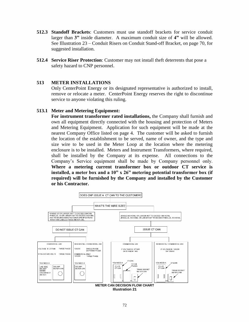
72
512.3 Standoff Brackets: Customers must use standoff brackets for service conduit
larger than 3” inside diameter. A maximum conduit size of 4” will be allowed.
See Illustration 23 – Conduit Risers on Conduit Stand-off Bracket, on page 70, for
suggested installation.
512.4 Service Riser Protection: Customer may not install theft deterrents that pose a
safety hazard to CNP personnel.
513 METER INSTALLATIONS
Only CenterPoint Energy or its designated representative is authorized to install,
remove or relocate a meter. CenterPoint Energy reserves the right to discontinue
service to anyone violating this ruling.
513.1 Meter and Metering Equipment:
For instrument transformer rated installations, the Company shall furnish and
own all equipment directly connected with the housing and protection of Meters
and Metering Equipment. Application for such equipment will be made at the
nearest Company Office listed on page 4. The customer will be asked to furnish
the location of the establishment to be served, name of owner, and the type and
size wire to be used in the Meter Loop at the location where the metering
enclosure is to be installed. Meters and Instrument Transformers, where required,
shall be installed by the Company at its expense. All connections to the
Company’s Service equipment shall be made by Company personnel only.
Where a metering current transformer box or outdoor CT service is
installed, a meter box and a 10” x 26” metering potential transformer box (if
required) will be furnished by the Company and installed by the Customer
or his Contractor.
METER CAN DECISION FLOW CHART
Illustration 21

73
513.2 Instrument Transformer Installations
Applications: When the ampacity of the Service Entrance Conductors is greater
than the ampacity of the Meter Mounting Device Information shown on page 72,
it will be necessary for the Company to use current transformers in the metering
installation. Potential transformers will be required on 480 volt and 480Y/277
volt services.
Overhead Service: Where service is provided by Overhead Service Drops,
current transformers will be mounted in a Metering Current Transformer Box in
accordance with ARTICLE 513.5; or, they may be mounted outdoors without a
Metering Current Transformer Box in accordance with ARTICLE 513.7. When
required, potential transformers shall be mounted in a metering potential
Transformer Box in accordance with Article 513.4. See Illustration 24 – Typical
Outdoor Metering for Single Customer. Service requiring current transformer
installations may be paralleled in accordance with requirements outlined in
Articles 513.3-513.9.

74
513.3 Metering Potential Transformer Box
Where a metering current transformer box or outdoor CT service is installed for
480 volt or 480Y/277 volt service, a 10” x 26” Metering Potential Transformer
Box will be furnished by the Company and installed by the Customer or his
contractor. The 10”x 26” metering potential transformer box shall be mounted
between 4ft and 6ft above ground or floor level. Where a metering current
transformer box is installed, the 10” x 26” metering potential transformer box
shall be connected to the metering current transformer box with 1 ¼” conduit or a
1 ¼” nipple. Where an outdoor CT service is installed, 1 ¼” conduit shall be run
from the 10” x 26” metering potential transformer box to the bottom of the 7 point
rack. An outdoor weatherhead shall be installed on the conduit. The placement of
the 10” x 26” metering potential transformer box shall not exceed 50’ in distance
from the current transformer mounting location.
513.4 Meter Box
Meter box will be installed adjacent to the metering potential transformer box and
connected with a 1 ¼” conduit or nipple using the pre-cut 1 ¼ in. knockout holes
at the base of the meter can. Where a metering potential transformer box is not
required, the meter box will be installed with the same mounting requirements as
the metering potential transformer box as listed in Article 513.3.
INDOOR MOUNTED CURRENT TRANSFORMERS
513.5 Metering Current Transformer Box (C.T. Can)
Metering Current Transformer Boxes will be furnished by the Company and
installed by the Customer or his Contractor. For Services with ampacity in excess
of the Self Contained Meter Device Chart shown on page 44 or 72, a 30” x 42”
Metering Current Transformer Box should be used. (See Article 514.2 for wiring
methods.) The Service Entrance Phase Conductors installed in a Metering
Current Transformer Box may be made up of one wire (600 KCMIL through
1,000 KCMIL conductor) or two identical wires in parallel per phase (300
KCMIL through 500 KCMIL conductors). Each pair of paralleled phase
conductors shall be the same color or shall be taped together or otherwise marked
for easy identification. Conductors may not be paralleled where the total
combined area per phase is less than 600 KCMIL (two 300 KCMIL) or greater
than 1,000 KCMIL (2-500 KCMIL). NO MORE THAN TWO
CONDUCTORS PER PHASE SHALL BE USED REGARDLESS OF
CONDUCTOR SIZE. When the total cross sectional area of Service Entrance
Conductors are greater than 1,000 KCMIL (2-500 KCMIL) per phase, a bus bar
type current transformer installation must be used, as shown in Illustration 25 –
Bus Bar Drilling in Current Transformer Box, next page.

75
513.6 Bus Bar Weatherhead: When the service entrance requires conductors greater
than 2-1000 KCMIL per phase, a bus bar type weatherhead must be used. If the
service entrance requires conductors less than or equal to 2-1,000 KCMIL per
phase, then the Customer may utilize either a bus bar type weatherhead or a
conventional type weatherhead installation (See Illustration 26 – Weatherhead
Arrangement for Outdoor Metering, page 67) or Illustration 24, page 73 with
outdoor current transformers. See ARTICLE 513.7 – 514.2 for outdoor current
transformer installation. Typical details of a bus bar type weatherhead are shown
in the Illustrations 27-30, on pages 76-79. All bus bar weatherheads must be
approved by Company personnel.

76

77

78

79

80
OUTDOOR MOUNTED CURRENT TRANSFORMERS (Outdoor C.T.)
513.7 Service Entrance Phase Conductors: Where a building is designed to be
occupied by a single Customer (one meter) and is served from an Overhead
Service Drop, one set of outdoor mounted current transformers may be utilized.
Where potential transformers are required, see Article 513.3. Service Entrance
Phase Conductors for outdoor metering transformer installations may be made up
of one wire (600 KCMIL through 1,000 KCMIL conductor) or two identical wires
per phase (300 KCMIL through 1000 KCMIL conductors). Each pair of parallel
phase conductors shall be of the same color or shall be taped together securely or
otherwise marked for easy identification. Conductors may not be paralleled
where the total combined area per phase is less than 600 KCMIL (2-300 KCMIL)
or greater than 2,000 KCMIL (2-1000 KCMIL). NO MORE THAN TWO
CONDUCTORS PER PHASE SHALL BE USED REGARDLESS OF
CONDUCTOR SIZE.
513.8 Mounting Devices: Where Service Entrance Conductors do not exceed 2-500
KCMIL per phase, the current transformers will be mounted on a standard
secondary rack installed by the Customer or his Contractor in accordance with
Illustration 26 – Weatherhead Arrangements for Outdoor Metering, on page 67.
The Customer shall attach the rack to his structure with two 5/8” galvanized
machine bolts of such length that the threaded end of the bolt will extend 2”
beyond the surface of the wall, and the bolts are to be anchored so that each bolt
will be capable of withstanding a pull of 300 lbs. Where Service Entrance
Conductors exceed 2-500 KCMIL (1-1,000 KCMIL) per phase, the current
transformers will be mounted on a separate mounting bracket supplied and
installed by the Company. The Customer shall install two ½” galvanized bolts
with the threaded ends protruding 2” from the wall in accordance with Illustration
26 – Weatherhead Arrangements for Outdoor Metering, on page 67.
513.9 Service Mast Installations: Where a service mast type installation is used in
conjunction with outdoor mounted current transformers, the Customer shall
provide 1 ¼” conduit through the roof connecting to the 10” x 26” meter
box/metering potential transformer box.
513.10 Customers Ineligible for Outdoor C.T. Service: In a building where more than
one Customer (more than one meter) is to be served from a single Overhead
Service Drop, outdoor metering shall not be used and each Customer (meter)
requiring current transformers must install a Metering Current Transformer Box
(and a Metering Potential Transformer Box, if required.) However, where service
has been provided to a building occupied by only one Customer (one meter)
utilizing outdoor mounted metering transformers and the building is later divided
so as to add one or more additional Customers (meters), the added Customers will
be served through self-contained metering or current transformer metering as
required. Each added Customer requiring current or potential transformers must
install a metering Current Transformer Box (and a Metering Potential

81
Transformer Box, if required) and a protective meter box. The original outdoor
metered service may be retained, but not more than two additional weatherheads,
with a maximum of 1-1,000 KCMIL per phase in each weatherhead, will be
connected to the Service Drop, provided the total combined load does not exceed
1,500 kVA.
513.11 Meter Equipment Bonding:
The customer is responsible for bonding connections.
All non-current carrying metallic parts to be effectively bonded with
copper conductors.
The Meter Box, PT Box and CT Box shall be bonded with nut/bolt
bonding lugs.
The equipment bonding jumper for CT Box shall be #1/0 CU minimum.
From the Meter Box to the CT Box, the bonding conductor shall be #8 CU
marked in accordance with the NEC.
The Company will install the secondary wiring between the instruments
transformers and the meter. Also, the Company will install the final
bonding connection to system neutral.

82
514 METHODS OF INSTALLING METERING EQUIPMENT
514.1 Metering current and potential transformer boxes and meter boxes shall be
installed by the Contractor with a free space of at least 36” in front and 2” on the
sides, and 6” on top and bottom, as necessary clearance to install, remove, and to
test equipment. The free space shall be over the Customer’s property or public
ways and shall not encroach upon the property of others even though there may be
a utility easement in the area of encroachment. The Customer shall install a meter
box as required at a location which will provide these clearances and which will
meet all conditions listed in Article 513.
514.2 Where a Metering Current Transformer Box is used, it should be mounted with
the service and load conduits entering and leaving on opposite end sections of the
box. If necessary, the conduit may enter the back of the box at the extreme ends.
The length of both line and load leads entering the Metering Current Transformer
Box shall be 48” for 30” x 42” boxes. If both line and load conduits must enter
one end section of the 30” x 42” box, one set of lead must be 72” long and the
other set of leads must be 48” long. Holes cut in Metering Current Transformer
Boxes must be cut with a hole cutter and must not be burned. If hubs are installed
in Metering Current Transformer Boxes, they must not be welded, brazed, or
soldered. See Illustration 32-Current Transformer Box Modification.

83
515 METER LOCATION
515.1 In all cases, the meter shall be located in a position that is readily accessible
to Company employees at all times without Customer assistance. Access to
the meter shall not be blocked by gates, walls or fences.
515.2 All instrument transformer rated meters shall be installed outdoors where
practical. In locations where outdoor installations are impractical, commercial
and industrial meters may be installed indoors; but the Company must be
consulted prior to the installation.
515.3 Meters shall not be located where they will interfere with traffic on sidewalks or
driveways, or where they will obstruct the opening of doors or windows.
515.4 In those special cases where metering equipment is installed indoors, it shall be
located in a clean, dry place, free from vibration and readily accessible during
normal working hours. It shall not be installed in toilets, bathrooms, elevators
shafts, boiler rooms, attics, balconies, kitchens, stairways, ventilators, storage
sheds, moving machinery or hazardous locations.
515.5 Metering equipment shall be installed on a wall which is a substantial part of the
building itself or on a meter pole. Temporary partitions, etc., which are subject to
replacement or excessive vibration shall not be used. Meters or metering
equipment shall not be installed on the Company’s poles.
515.6 Meters or current transformers shall not be installed in or directly on switchgear
cabinets.
516 METER SEALS
It is the regular practice of the Company to seal or lock all meters, meter test
switches, terminal boxes, current transformer cabinets and terminals of current
transformers. No one but the Company’s agents and persons authorized by law
are permitted to remove a Company seal or lock.

84
517 INSTRUMENT TRANSFOMER RATED METER INSTALLATION
SEQUENCE
THE SEQUENCE OF CONNECTIONS SHALL BE AS FOLLOWS:
SERVICE – METER – SWITCH – FUSE - LOAD
For certain multi-level structures, the most feasible method of serving
individually metered tenants often includes metering gutters located within the building
proper and remote to the Point of Delivery of Electric Service. With such service
arrangements, National Electrical Code requirements, building design, and Customer
wiring costs also make the installation of a disconnecting means between the Point of
Delivery and the remote metering gutter a desirable alternative. REQUESTS FOR THE
INSTALLATION OF A DISCONNECTING MEANS ON THE LINE SIDE OF A
REMOTE METERING GUTTER MUST BE REFERRED TO ELECTRIC
ENGINEERING FOR APPROVAL OF THE ARRANGEMENT DURING EARLY
DESIGN STAGES, PRIOR TO INSTALLATION OF EQUIPMENT. Failure to
obtain the required approval may result in the Company refusing to energize equipment
installed by the Customer. The sequence of connections for individual meter installations
served from a metering gutter shall be as stated above. The service disconnecting means
shall be installed at a readily accessible location either outside of a building or structure,
or inside nearest the point of entrance of the service conductors. The intent of the
foregoing is to locate the disconnecting means as close as possible to the meter. For all
new services, Company personnel must be able to verify that the main disconnect is
open before energizing service.

85

86

87
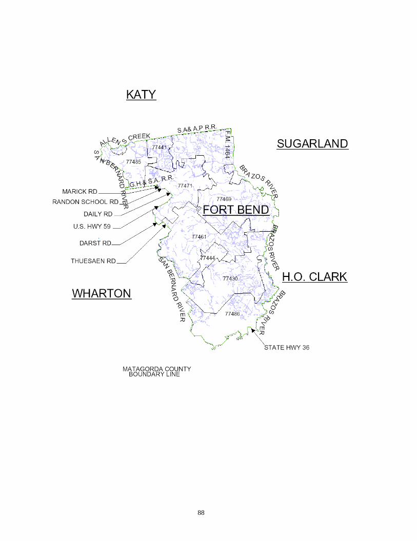
88

89

90

91

92

93

94

95

96

97
LONE STAR NOTIFICATION CENTER
OSHA Rule 1926.651 Requires Previous Notification
CALL BEFORE YOU DIG
713-223-4567
or Toll Free
1-800-669-8344
Or 811 (www.call811.com) nationwide number
When you need to evacuate in the Houston area, there is a single number you can call
to be sure you don’t encounter the inconvenience of digging into underground power lines.
Just call the special operator who is on duty 24 hours a day, seven days a week at 223-
4567 or 1-800-669-8344. Tell the operator who, what, when and where about your excavation
plans at least 48 hours before you begin. You message is relayed to each of the area
utilities. If they have underground lines in the area, they will either contact you directly, or
will stake out the job site with color coded markers to show you where their lines are located.
Here are the colors:
Red – Electric power lines or conduits.
Orange – Communication lines or other hazardous lines.
Yellow – Gas, oil, petroleum or other hazardous lines.
Green – Storm and sanitary sewer lines.
Blue – Water lines
If, for any reason, you should cut an underground line, the same numbers can also be
used to notify any of the utilities. So remember these numbers, and save yourself time and
trouble when you need to dig.
713-223-4567 or Toll Free 1-800-669-8344 or 811