palisades plant - inservice testing program plan fifth 10 ... · (pnp) inservice testing (ist)...
TRANSCRIPT

~Entergy Entergy Nuclear Operations, Inc. Palisades Nuclear Plant 27780 Blue Star Memorial Highway Covert, Ml 49043-9530 Tel 269-764-2000
Jeffery A. Hardy Regulatory Assurance Manager
PNP 2016-006
April 28, 2016
U.S. Nuclear Regulatory Commission ATTN: Document Control Desk Washington, DC 20555-0001
SUBJECT: lnservice Testing Program Plan Fifth 10-year Interval
Palisades Nuclear Plant Docket 50-255 Renewed Facility Operating License No. DPR-20
References: 1. Entergy Nuclear Operations, Inc. letter to NRC, PNP 2015-024, Relief Requests, Proposed Alternatives, for the Fifth 10-Year lnservice Test Interval, dated May 19, 2015 (ADAMS Accession Number ML 15142A643)
2. NRC e-mail to Entergy Nuclear Operations, Inc., Palisades - Request for Additional Information Regarding the Relief Request No. RR 5-2 (MF6248), dated August 19, 2015 (ADAMS Accession Number ML15231A586)
3. Entergy Nuclear Operations, Inc. letter to NRC, PNP 2015-069, Response to Request for Additional Information - Palisades Nuclear Plant Relief Request No. RR 5-2, dated September 09, 2015 (ADAMS Accession Number ML 15253A682)
4. NRC letter to Entergy Nuclear Operations, Inc., Palisades Nuclear PlantRe/ief Request Numbers 5-2 and 5-3, Proposed Alternative to the Requirements of the ASME OM Code for the Fifth 10-Year lnservice Test Interval (GAG No. MF6248), dated December 22, 2015 (ADAMS Accession No. ML 15334A307)
Dear Sir or Madam:
Pursuant to 1 O CFR 50.55a, Codes and standards, and American Society of Mechanical Engineers (ASME) Operation and Maintenance (OM) Code-2004, Code for Operation and Maintenance of Nuclear Power Plants, Section ISTA-3200, Administrative Requirements, Entergy Nuclear Operations, Inc. (ENO) hereby submits the enclosed Palisades Nuclear Plant's (PNP) inservice testing (IST) program plan for the fifth 10-year interval, which began on March 24, 2016. .
Pursuant to 1 O CFR 50.55a(f), lnservice testing requirements, as conditioned by 1 O CFR 50.55a(b), Use and conditions on the use of standards, PNP's plan will comply with the ASME OM Code, 2004 Edition through the 2006 Addenda as altered by 1 O CFR 50.55a(z), Alternatives to codes and standards requirements. fl 11
/1 J.lf-e_

PNP 2016-006 Page 2 of 2
In Reference 1, PNP proposed two alternative, relief requests to the requirements of the ASME OM Code for the duration of the fifth 10-year IST interval, RR 5-2 and HR 5-3. RR 5-2 proposed to apply ASME OM Code Case OMN-20, lnservice Test Frequency, in lieu of the test frequency requirements of the ASME OM Code. RR 5-3 requested relief from the stroke time testing requirements of ASME OM Code, subsection ISTC paragraph ISTC-5131, Valve Stroke Testing, for two pneumatically operated valves, due to impracticality of performance. In Reference 2, the NRC requested additional information (RAI) associated with RR 5-2. In Reference 3, PNP provided a response to the NRC RR 5-2 RAI. In Reference 4, the NRC staff authorized use of the proposed alternatives in requests RR 5-2 and RR 5-3.
This letter contains no new commitments and no revised commitments.
Sincerely,
9~\~(/. JAH/jpm
Enclosure: Entergy Nuclear Operations, Inc., Palisades Nuclear Plant, Palisades lnservice Testing Program Plan Fifth 10-Year Interval
cc: Administrator, Region Ill, USNRC Project Manager, Palisades, USNRC Resident Inspector, Palisades, USNRC
ENCLOSURE
ENTERGY NUCLEAR OPERATIONS, INC.
PALISADES NUCLEAR PLANT
Palisades lnservice Testing Program Plan
Fifth 10-Vear Interval
27 4 pages follow

ENTERGY NUCLEAR OPERATIONS, INC.
PALISADES NUCLEAR PLANT 27780 Blue Star Memorial Highway
Covert, Michigan 49043-9530
Commercial Service Date: December 31, 1971
lnservice Testing (IST) Program Plan
Fifth Ten-Vear Interval March 24, 2016 - March 23, 2026
Page 1
1.0
2.0
3.0
4.0
5.0
Palisades Nuclear Plant lnservice Testing (IST) Program Plan
Fifth Ten-Year Interval
Table of Contents
lnservice Testing Program Description
SEP-PLP-IST-101, lnservice Testing of Plant Valves
SEP-CV-PLP-002, Check Valve Condition Monitoring and lnservice Testing Program
SEP-PLP-IST-102, lnservice Testing of Selected Safety Related Pumps
Deferred Test Justifications
Page 2
Page 3
Page 4
Page 148
Page 194
Page 245
Palisades Nuclear Plant lnservice Testing (IST} Program Plan
Fifth Ten-Vear Interval
Section 1.0
lnservice Testing Program Description
Palisades lnservice Testing (IST) Program plan is implemented through three site Engineering Program Sections. When combined these three Engineering Program Sections describe how the Palisades IST Program satisfies the regulatory requirements of Title 1 O of the Code of Federal Regulations, Part 50, Section 55a (1 O CFR 50.55a, "Codes and Standards") and the ASME OM Code, 2004 Edition, with Addenda through 2006, "Operations and Maintenance of Nuclear Power Plants, Subsections ISTA, ISTB, ISTC, Mandatory Appendix I, and Mandatory Appendix 11". The three IST Engineering Program Sections are:
SEP-PLP-IST-101, "lnservice Testing of Plant Valves" SEP-CV-PLP-002, "Check Valve Condition Monitoring and lnservice Testing Program" SEP-PLP-IST-102, "lnservice Testing of Selected Safety-Related Pumps"
Page3

Palisades Nuclear Plant lnservice Testing (IST) Program Plan
Fifth Ten-Year Interval
Section 2.0
SEP-PLP-IST-101
lnservice Testing of Plant Valves
Page4
(143 pages follow)

Program Section No. SEP-PLP-IST-101 Revision 3
Pagei
INSERVICE TESTING OF PLANT VALVES
ENGINEERING NUCLEAR ENGINEERING PROGRAMS
APPLICABLE SITES
All Sites: D
Specific Sites: ANO D GGNS D IPEC D JAF D PLP rg] PNPS D RBS D VY D W3 D HQN D
Current Revision
3
2
1
Safety Related: Yes No
Program Section Revision Summary Description of Change
Revised section 2.1 to correct the IST interval start and end dates. Revised Attachment 7 to reflect Cold Shutdown Justification 31.
Revised the Program Section to reflect the 10 year code update from The ASME OM Code 2001 Edition through 2003 Addenda to the 2004 Edition through the 2006 Addenda.
Added references to Program Sections SEP-ISl-PLP.:003, "Palisades lnservice Inspection Master Plan Fourth Interval, ASME Section XI, Division 1" and CEP-RR-001, "ASME Section XI Repair/Replacement Program" as 3.2.3.i and 3.2.3.j per WT-WTPLP-2012-00427 CA-37 and WT-PLF~-2012-00427 CA-43
· Added a statement to section 5.5.3 that the check valves in the Condition Monitoring program are identified by the Condition Monitoring Analysis (CMA) number in Attachment 10 perWT-PLP-2012-00427 CA-41
Added references 3.1.16 and 3.1.17 for the NRC correspondence related to Palisades fourth 10 year interval update per WT-WTPLP-2012-00141 CA-1
Added Cold Shutdown justifications CS34, CS35, and CS36 to Attachment 4 per WTWTPLP-2012-00427 CA-45 and added CR-PLP-2013-02543 as reference 3.2.8.j
Revised the approval section of Attachment 8 to require the Preparer of the IST Valve Reference Value(s)/Range(s) Change Form to be a qualified IST Engineer instead of the approver. A non IST qualified individual should not be preparing the change form. This requires the preparer to be qualified and allows approval by the supervisor or another knowledgeable person.
Revised Attachment 10 to reflect the correct Condition Monitoring Analyses (CMA's) per CR-PLP-2014-04891 CA-2 and WT-WTPLP-2013-00044 CA-5.
0
Program Section No. SEP-PLP-IST-101 Rev.ision 3
Page ii
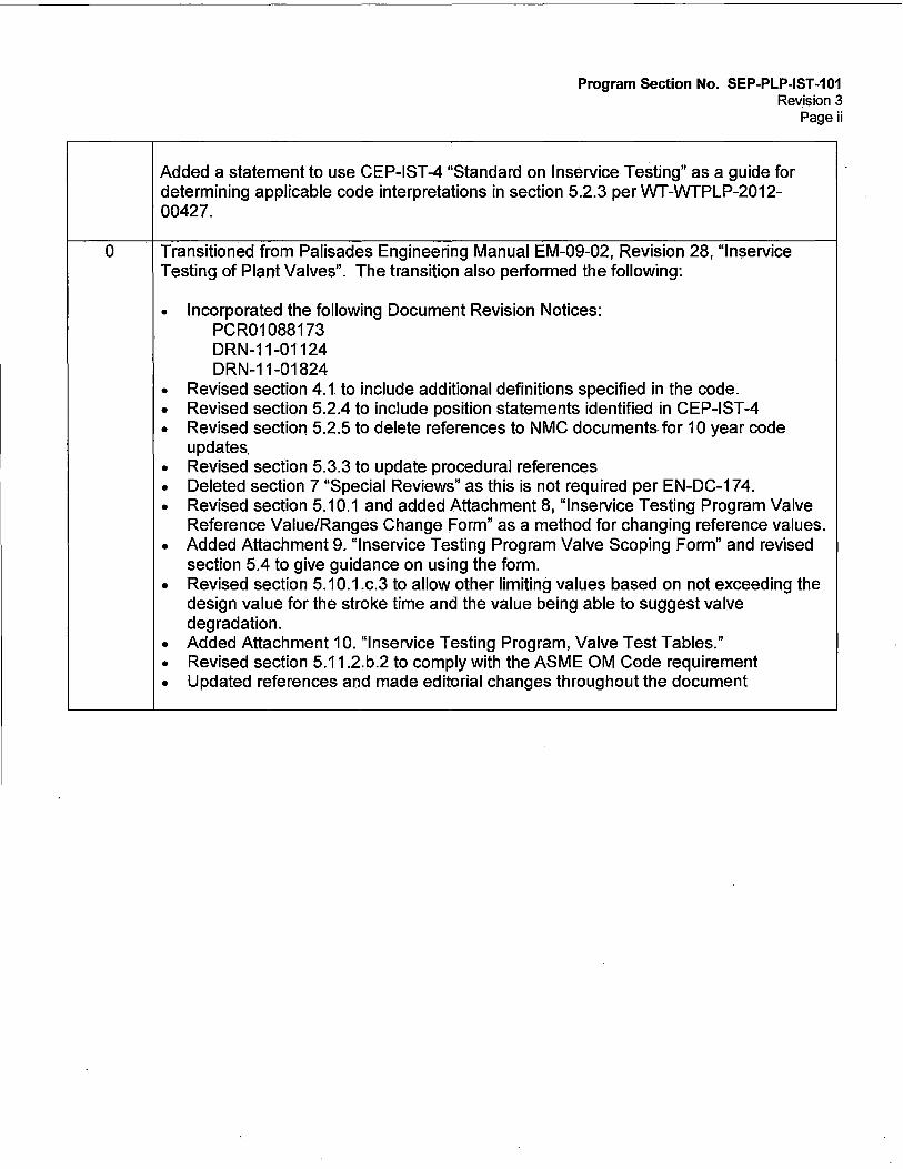
Added a statement to use CEP-IST-4 "Standard on lnservice Testing" as a guide for determining applicable code interpretations in section 5.2.3 per WT-WTPLP-2012-00427.
Transitioned from Palisades Engineering Manual EM-09-02, Revision 28, "lnservice Testing of Plant Valves". The transition also performed the following:
• Incorporated the following Document Revision Notices: PCR01088173 DRN-11-01124 DRN-11-01824
• Revised section 4.1 to include additional definitions specified in the code . • Revised section 5.2.4 to include position statements identified in CEP-IST-4 • Revised section 5.2.5 to delete references to NMC documents for 10 year code
updates. • Revised section 5.3.3 to update procedural references • Deleted section 7 "Special Reviews" as this is not required per EN-DC-174 . • Revised section 5.10.1 and added Attachment 8, "lnservice Testing Program Valve
Reference Value/Ranges Change Forrn" as a method for changing reference values. • Added Attachment 9. "lnservice Testing Program Valve Scoping Form" and revised
section 5.4 to give guidance on using the form. • Revised section 5.10.1.c.3 to allow other limiting values based on not exceeding the
design value for the stroke time and the value being able to suggest valve degradation.
• Added Attachment 10. "lnservice Testing Program, Valve Test Tables." • Revised section 5.11.2.b.2 to comply with the ASME OM Code requirement • Updated references and made editorial changes throughout the document

\ Program Section No. SEP-PLP-IST-101 Revision 3
Page iii REVIEW AND CONCURRENCE SHEET
Program Section Title: lnservice Testing Of Plant Valves
Prepared By: G Katt A.K~ Date: 4-22-16
Checked By: RWhite~ Date: 4-22-16
Reviewed By: N/A N/A (Optional) Date:
ANll: N/A N/A Date:
(Reviewed By or N/ A)
Concurred: hct K<Z*f +or ~M.'.!~t f><r R\ ~ c OA
JM Jerz Date: 4-22-16 Responsible Supervisor

SECTION Main Body Attachment 1 Attachment 2 Attachment 3 Attachment 4 Attachment 5 Attachment 6 Attachment 7
REVISION STATUS SHEET
PAGE NO. All All All All All All All All
Program Section No. SEP-PLP-IST-101 Revision 3
Page iv
REVISION 3 3 3 3 3 3 3 3

/
Table of Contents
Program Section No. SEP-PLP-IST-101 Revision 3
Pagev
1.0 PURPOSE ...................................................................................................................... 1
2.0 SCOPE ........................................................................................................................... 1
3.0 REFERENCES ............................................................................................................... 2
3.1 SOURCE DOCUMENTS ................................................................................ 2
3.2 REFERENCE DOCUMENTS ......................................................................... 5
4.0 DEFINITIONS AND RESPONSIBILITIES .................................................................... 10
4.1 DEFINITIONS ............................................................................................... 10
4.2 RESPONSIBILITIES .................................................................................... 12
5.0 PROCEDURE ............................................................................................................... 13
5.1 PROGRAM DESCRIPTION ......................................................................... 13
5.2 REGULATIONS AND CODES ..................................................................... 13
5.3 PLANT PROCEDURES ............................................................................... 15
5.4 CATEGORIZATION OF VALVES IN IST PROGRAM ................................. 17
5.5 TYPE OF TESTING REQUIRED FOR VALVE CATEGORIES .................... 17
5.6 METHODS OF TESTING VALVE FUNCTIONS .......................................... 17
5.7 GROUPING SIMILAR VALVES FOR TESTING EFFICIENCIES ................ 18
5.8 INTERVALS FOR TESTING VALVES ......................................................... 18
5.9 SCHEDULING VALVE INSERVICE TESTS ................................................ 22
5.10 CRITERIA FOR ACCEPTING TEST RESULTS .......................................... 22
5.11 VALVE FAILURE/CORRECTIVE ACTION .................................................. 26
5.12 TRENDING ................................................................................................... 29
6.0 ATTACHMENTS AND RECORDS ............................................................................... 35
6.1 ATTACHMENTS .......................................................................................... 35
6.2 RECORDS ................................................................................................... 35

Table of Contents
ATTACHMENTS
Attachment 1, "lddeal Concepts Software Suite®" Attachment 2, "Cold Shutdown Justification Index" Attachment 3, "Refueling Outage Justification Index" Attachment 4, "Relief Request Justification Index"
Program Section No. SEP-PLP-IST-101 Revision 3
Page vi
Attachment 5, "lnservice Testing Program Valve Reference Value/Ranges Change Form" Attachment 6, "lnservice Testing Program Valve Scoping Form" Attachment 7, "Valve Summary Listing"

1.0 PURPOSE
Program Section No. SEP-PLP-IST-101 Revision 3
Page 1of36
1.1 To describe how the Palisades lnservice Testing (IST) Valve Program satisfies the regulatory requirements of Title 10 of the Code of Federal Regulations, Part 50, Section 55a (10 CFR 50.55a, "Codes and Standards") and Technical Specifications.
1.2 To provide an overview of the Palisades procedures and processes used to administer and implement the IST Valve Program.
1.3 To identify regulatory, code, and guidance documents that provide specific requirements (including scope, categorization, type and methods of testing, acceptance criteria, corrective actions, and documentation) and guidance (including grouping valves, non intrusive testing techniques, and requests for regulatory relief) for inservice testing of valves.
1.4 To outline the process of scheduling tests, testing valves, evaluating test results, taking corrective actions, trending test results, and documenting valve information pertinent to the Palisades IST Valve Program.
1.5 For details related to the Palisades check valve IST program, refer to Site . Engineering Program SEP-CV-PLP-002, "Check Valve Condition Monitoring and lnservice Testing Program."
2.0 SCOPE
2.1 This procedure is developed to the requirements (with exception of the relief requests) of 10 CFR 50.55a, March 2015 Edition; which incorporates by reference the Code for Operations and Maintenance of Nuclear Power Plants, 2004 Edition with Addenda through 2006 identified in this procedure as the Code.
The requirements of these regulations and codes were implemented on March 24, 2016 and are in effect through Palisades' fifth 120-month interval ending March 23, 2026.
2.2 This procedure applies to ASME Class 1, 2, and 3 valves as specified in 10 CFR 50.55a and in Technical Specifications ADMIN 5.5.7. The Code of Federal Regulation (10 CFR 50.55a(f)(4)) requires valves that are Class 1, 2, and 3 valves be tested in accordance with the ASME OM Code.
2.3 This procedure applies to ASME Class or Non-Class valves that are tested in accordance with commitments Palisades has made with the NRC.
2.4 This procedure may be applicable to Non-Class valves, including:
a. . Certain components that are outside the scope of the Code but have Technical Specifications Surveillance Testing Requirements.

Program Section No .. SEP-PLP-IST-101 Revision 3
Page 2 of 36
b. Certain components that are outside the scope of the Code but have a specific function in shutting down the reactor to Technical Specification Mode 5 or in mitigating the consequences of an accident.
c. Certain components that are outside the scope of the Code, but are deemed important by the owner to test.
2.5 Nothing in the Code shall be construed to supersede the requirements of any Technical Specifications. When requirements of the ASME Code and Technical Specifications conflict, either the Technical Specifications shall be changed, or the provisions of the more stringent program shall be followed.
2.6 Site Engineering Program Section SEP-ISl-PLP-002, "ASME Code Boundaries For ASME Section XI lnservice Inspection Program," provides the ASME boundary classifications for valves, and references the Color Coded P&IDs as a visible means of identifying what we have committed to as the plant Code Boundaries.
2.7 The plant valves that are in scope to the inservice test program are identified in Attachment 10, "lnservice Testing Program, Valve Test Tables".
2.8 The OM Code excludes the following valves from the IST requirements of this procedure, provided that they are not required to perform a specific safety function:
a. Valves used only for operating convenience, such as vent, drain, and instrument and test valves.
b. Valves used only for system control, such as, pressure regulating, temperature control and flow control and without a safety related fail safe function.
c. Valves used only for system or component maintenance.
2.9 In accordance with the OM Code, skid-mounted valves are excluded from the requirements of the IST Program, provided that they are adequately tested as part of the major component
2.10 1 OCFR50.55a(b)(3)(ii) OM condition: Motor-Operated Valve (MOV) testing. Licensees must comply with the provisions for MOV testing in OM Code ISTC 4.2, 1995 Edition with the 1996 and 1997 Addenda, or ISTC-3500, 1998 Edition through the latest edition and addenda incorporated by reference in paragraph (a)(1 )(iv) of that section, and must establish a program to ensure that motor-operated valves continue to be capable of performing their design basis safety functions.
3.0 REFERENCES
3.1 SOURCE DOCUMENTS

Program Section No .. SEP-PLP-IST-101 Revision 3
Page 3 of 36
3.1.1 Technical Specifications SR 3.0.1, SR 3.0.2, ,SR 3.0.3, SR 3.0.4
3.1.2 Technical Specifications ADMIN 5.5.7 3.1.3 Technical Specifications Bases Table B 3.4.14-1
3.1.4 Final Safety Analysis Report - 6.9.2.2
3.1.5 Code of Federal Regulations Title 10, Part 50, Section 55a (10 CFR 50.55a), "Codes and Standards"
3.1.6 Code of Federal Regulations Title 10, Part 50, Appendix B, "Quality Assurance Criteria for Nuclear Power Plant and Fuel Reprocessing Plants"
3.1.7 , Code of Federal Regulations Title 10, Part 50 (10 CFR 50), Appendix J, "Primary Reactor Containment Leakage Testing for Water-Cooled Reactors"
3.1.8 ASME OM Code, 2004 Edition, with Addenda through 2006, "Operations and Maintenance of Nuclear Power Plants, Subsections ISTA, ISTB, ISTC, ISTD, Mandatory Appendix I, and Mandatory Appendix 11"
3.1.9 USNRC NUREGs, Generic Letters, Information Notices, and IE Bulletins
a. Generic Letter 87-06, "Periodic Verification of Leak Tight Integrity of Pressure Isolation Valves" (362111538)
b. Generic Letter 89-04, "Guidance on Developing Acceptable lnservice Testing Programs" (D074/2279)
c. Generic Letter 89-10, "Safety Related Motor Operated Valve Testing and Surveillance" (D121/0323, Supplement D256/0378)
d. Generic Letter 96-05 - Periodic Verification of Design-Basis Capability of Safety-Related Power-Operated Valves
e. Generic Letter 96-06 - Assurance of Equipment Operability and Containment Integrity During Design-Basis Accident Conditions
f. NUREG 0737, "Clarification of TAI Action Plan Requirements" (C/F - 9427/1033)
g. NUREG-1482, Rev 2 "Guidelines for lnservice Testing at Nuclear Power Plants"
h. NUREG/CR-6396, "Examples, Clarifications, and Guidance on Preparing Requests for Relief from Pump and Valve lnservice Testing Requirements"

Program Section No. SEP-PLP-IST-101 Revision 3
Page4 of 36
i. Memorandum: Summary of Public Workshops Held in NRC Regions on Inspection Procedure 73756, "lnservice Testing of Pumps and Valves," and Answers to Panel Questions on lnservice Testing Issues, Joseph Colaccino, July 18, 1997
3.1.10 Entergy Quality Assurance Program Manual (QAPM)
3.1.11 Miscellaneous Correspondence
a. NRC letter dated January 13, 1978 (C/F -2511/2358)
b. NRC Ord~r dated April 20, 1981 regarding Event V PIVs (C/F - 9018/1126)
c. Palisades letter to the NRC dated June 5, 1987, Palisades Plant Response to Generic Letter 87-06 - Periodic Verification of Leak Tight Integrity of Pressure Isolation Valves"
3.1.12 Other Codes, Standards, and Guides
a. ANSI/ANSI 51.1, 1983, "American National Standard Nuclear Safety Criteria for the Design of Stationary Pressurized Water Reactor Plants"
b. Regulatory Guide 1.26, "Quality Group Classifications and Standards for Water, Steam and Radioactive Waste Containing Components of Nuclear Power Plants"
c. ANSI N45.2.6, 1978, "Qualifications of Inspection, Examination and Testing Personnel for Nuclear Power Plants"
d. ANSI N18.7, "Administrative Controls and Quality Assurance for Operational Phase of Nuclear Power Plants"
e. Nuclear Energy Institute (NEI) White Paper entitled, "Standard Format for Requests from Commercial Reactor Licensees Pursuant to 10 CFR 50.55a, Revision 1," dated June 7, 2004 (ADAMS Accession No. ML070100400)
3.1.13 Plant Equipment Data Base (EDB)
3.1.14 Plan·t Piping and Instrument Diagrams (P&IDs)
3.1.15 NRC Letter to Palisades, dated March 22, 2007. "Palisades Nuclear Plant - Request For Relief From lnservice Testing Requirements For The Fourth 10-Year Pump And Valve lnservice Testing Program: (TAC Nos. MD1122, MD1123, MD1124, MD1125, MD1126, MD1127, AND MD1163)"
Program Section No. SEP-PLP-IST-101 Revision 3
Page 5 of 36
3.1.16 NRC Letter to Palisades, dated December 22, 2015, Palisades Nuclear Plant- Relief Request Numbers RR 5-2 and 5-3, Proposed Alternative To The Requirements of the ASME OM Code For The Fifth 10-Year lnservice Test Interval (CAC No. MF6248)
3.2 REFERENCE DOCUMENTS
3.2.1 Final Safety Analysis Report - 5.1.6.6 and 6.9.2.2
3.2.2 Palisades Administrative Procedures:
a. 3.19, "Technical Specifications Programs"
b. 5.19, "Post Maintenance Testing"
c. 9.20, "Technical Specification Surveillance and Special Test Program"
d. 10.51, "Writer's Guideline for Site Procedures"
3.2.3 Site Engineering Manuals and Programs:
a. EM-04-08, "Shutdown Margin Requirements"
b. SEP-APJ-10, "Containment Leak Rate Testing Program"
c. SEP-CV-PLP-002, "Check Valve Condition Monitoring and lnservice Testing Program"
d. SEP-MOV-PLP-001, "Motor Operated Valve Program"
e. SEP-CV-PLP-001, "Check Valve Program"
f. SEP-AOV-PLP-001, "Air and Solenoid Operated Valve Program"
g. SEP-MOV-PLP-002, "Motor Operated Valve (MOV) Periodic Verification and Trending Program"
h. SEP-RV-PLP-001, "Relief Valve Program Standard"
i. Program Section SEP-ISl-PLP-003, "Palisades lnservice Inspection Master Plan Fifth Interval, ASME Section XI, Division 1"
j. Program Section CEP-RR-001, "ASME Section XI Repair/Replacement Program"
3.2.4 Technical Specification Surveillance Procedures:

Program Section No. SEP-PLP-IST-101 Revision 3
Page 6 of 36
a. M0-7A-1, "Emergency Diesel Generator 1-1"
b. M0-7A-2, "Emergency Diesel Generator 1-2"
c. Q0-1, "Safety Injection System"
d. Q0-2, "Recirculation Actuation System"
e. Q0-5, "Valve Test Procedure (Includes Containment Isolation Valves)"
f. Q0-6, "Cold $hutdown Valve Test Procedure (Includes Containment Isolation Valves)"
g. Q0-8B, "ESS Check Valve Operability Test and LPSI Motor Operated Valve Position Verification Test (Modes 5 and 6)"
h. Q0-14, "lnservice Test Procedure - Service Water Pumps"
i. Q0-15, "lnservice Test Procedure - Component Cooling Water Pumps"
j. Q0-16, "lnservice Test Procedure - Containment Spray Pumps"
k. Q0-19, "lnservice Test Procedure - HPSI Pumps and ESS Check Valve Operability Test"
I. Q0-20, "lnservice Test Procedure - Low Pressure Safety Injection Pumps"
m. .Q0-21, "lnservice Test Procedure, Auxiliary Feedwater Pumps"
n. Q0-37, "Main Steam Isolation and Bypass Valve Testing"
o. Q0-41, "Main Feedwater Regulating Valves lnservice Stroke Test"
p. Q0-42, "Section XI Testing of Shutdown Cooling Control Valves"
q. Q0-43," Shutdown Cooling Bypass and Loop Isolation Valves lnservice Test"
r. Rl-17, "Main Steam Isolation Valve Circuits Test and Valve Closure Testing"
s. Rl-115, "Power Operated Relief Valves"
t. RM-29, "Main Steam Safety Valve Setpoint Testing"
u. R0-32, "LLRT - Local Leak Rate Test Main Procedure"
v. R0-52, "Fire Suppression Water System Functional Test and Fire Pump Capacity Test"

Program Section No. SEP-PLP-IST-101 Revision 3
Page 7 of 36
w. R0-65, "High Pressure Safety Injection (HPSI) Trains 1 and 2, and Hot Leg Injection (HLI) Check Valve Test and Cold Leg/Hot Leg Injection Flow Balance Test"
x. R0-98, "LPSI and Containment Spray Comprehensive Pump Test and Check Valves Test"
y. R0-105, "Full Flow Test for SIT Check Valves and PCS Loop Check Valves"
z. R0-112, "Reactor Head/Pressurizer Vent Flow Check"
aa. R0-119, "lnservice Testing of Engineered Safeguards Valves CV-3027 and CV-3056"
ab. R0-127, "Auxiliary Feedwater System, 18 Month Test Procedure"
ac. ·R0-143, "Nonintrusive Testing of Charging Header Check Valves and Charging Header Control Valve Testing"
ad. R0-144, "Comprehensive Pump Test Procedure, Service Water Pumps P-7A, P-78 and P-7C"
ae. R0-145, "Comprehensive Pump Test Procedure, Auxiliary Feedwater Pumps P-8A, P-88 and P-8C"
af. R0-146, "Comprehensive Pump Test Procedure, Component Cooling Water Pumps P-52A, P-528 and P-52C"
ag. R0-147, "Comprehensive Pump Test Procedure, High Pressure Safety Injection Pumps P-66A, P-668 and P-66C"
ah. RT-41, "Pressurizer Safety Valves RV-1039, RV-1040, and RV-1041"
ai. RT-71 L, "Technical Specification ADMIN 5.5.2 Pressure Test of ESS Pump Suction Piping"
aj. RT-116, "Miscellaneous Systems Safety Valve Setpoint Testing"
ak. S0-4A, "Personnel Air Lock Penetration Leak Test"
al. RT-122, "lnservice Test Program - Check Valve Disassembly and Inspection Program"
am. SH0-1, "Operator's Shift Items Modes 1, 2, 3, and 4"

Program Section No. SEP-PLP-IST-101 Revision 3
Page 8 of 36
an. R0-217, "Technical Specification Leak Rate Testing of Engineered Safeguards Check Valves"
ao. Technical Specification Surveillance Procedure RT-41, "Pressurizer Safety Valves RV-1039, RV-1040, and RV-1041"
ap. Technical Specification Surveillance Procedure RT-116, "Miscellaneous Systems Safety Valve Setpoint Testing"
aq. Technical Specification Surveillance Procedure RT-122, "lnservice Test Program - Check Valve Disassembly and Inspection Program"
3.2.5 Entergy Procedures:
a. EN-PL-155, "Entergy Nuclear Change Management"
b. EN-DC-167, "Classification of Structures, Systems, and Components"
c. EN-OP-104, "Operability Determination Process"
d. EN-DC-324, "Preventive Maintenance Program"
e. EN-WM-100, "Work Request (WR) Generation, Screening and Classification"
f. EN-AD-101, "Procedure Process"
g. EN-AD-103, "Document Control and Records Management Programs "
h. EN-DC-332, "lnservice Testing Duties and Responsibilities"
i. EN-Ll-102, "Corrective Action Process"
j. EN-WM-102, 'Work Implementation and Closeout."
k. EN-WM-101, "On line Work Management Process"
3.2.6 Other Procedures:
a. GOP-2, "Mode 5 to Mode 3 ~ 525°F"
b. GOP-9, "Mode 3 ~ 525°F to Mode 4 or Mode 5"
c. CH 6.30, "Process Monitor Operational Check - Quarterly"
d. Preoperational Test Procedure #12, "Engineered Safeguards System and Shutdown Cooling System"

Program Section No. SEP-PLP-IST-101 Revision 3
Page 9 of 36
e. MSM-M-60, "ASME Safety/Relief Valve Testing For Valves Included in ASME Section XI Scope"
f. MSM-M-70, "In-Place Testing of Safety/Relief Valves Using the KT3000 AccuTEST System"
g. SEP-ISl-PLP-002, "ASME Code Boundaries For ASME Section XI lnservice Inspection Progra,m
3.2.7 Preventive Maintenance Activities:
a. PMID 50085190-01, " CV-0884NOP-0884, Rebuild Valve/Operator"
b. PMID 50085191-01, "CV-0884NOP-0884, Rebuild Valve/Operator"
c. PMID 50083972-01, "FPS/SWS to AFW Valve PM"
d. PMID 50085512-01, "Manual Isolation Valve PM Program (CDS)"
e. PMID 50083974-01, "Manual Stroke of CV-2008 and CV-2010"
f. PMID 50083975-01, "Manual Operation of CV-0736A and CV-0737A"
3.2.8 Miscellaneous References:
a. Action Item Report A-RE-82-002, "Required SIRW Tank Volume" (C/F - 9084/0461)
b. Facility Change FC-441, Hot Leg Injection (0869/0536 and 9126/0004)
c. NOMIS. Report Request 90-04-081/Report Number 8163A (Located in Document Control Center)
d. Tech Data Book (Located in Document Control Center)
e. C-PAL-97-1380, "CV-0703 Failed Valve Position Verification" (4613/0420)
f. CEP-COS-100, Control and Use of lddeal Concepts Software
g. lddeal Concepts Software Suite®
h. Engineering Assistance Request EAR 99-0081, "CVCS Declassification"
i. Corporate Engineering Program CEP-IST-4 "Standard on lnservice Testing"
j. CR-PLP-2013-02543

4.0 DEFINITIONS AND RESPONSIBILITIES
4.1 DEFINITIONS
Program Section No. SEP-PLP-IST-101 Revision 3
Page 10 of 36
4.1.1 Exercising - A demonstration based on direct visual or indirect positive indications that the moving parts of a component function.
4.1.2 Full Stroke Time - The time interval from initiation of the actuating signal to the indication of the end of the operating stroke.
4.1.3 lnservice Test - A test to assess the operational readiness of a system, structure, or component .after first electrical generation by nuclear heat.
4.1.4 Instrument Loop - two or more instruments or components working together to provide a single output.
4.1.5 Instrument Loop Accuracy - The accuracy of an instrument loop based on the square root of the sum of the squares of the inaccuracies of each instrument or component in the loop when considered separately. Alternatively, the allowable inaccuracy of the instrument loop may be based on the output for a known input into the instrument loop.
4.1.6 Maintenance - The replacement of parts, adjustments, and similar actions that do not change the design (configuration and material) of an item.
4.1.7 Modification - The alteration in the design of a system, structure, or component. \
4.1.8 Monitoring - The continuous or periodic observation or measurement to ascertain the performance or obtain characteristics of a system, structure, or component.
4.1.9 Nonintrusive Testing - Testing that is performed on a component without disassembly or disturbing the boundary of the component.
4.1.10 Obturator - The valve closure member (disk, gate, plug, etc.).
4.1.11 Operational Readiness - The ability of a component to perform its specified functions.
4.1.12 Overpressure Protection - The means by which components are protected from overpressure by the use of pressure-relieving devices or other design provisions as required by the BPV Code, Section Ill, or other applicable construction codes.
4.1.13 Owner: - An organization owning or operating a facility where items are installed or used.

Program Section No. SEP-PLP-IST-101 Revision 3
Page 11 of 36·
4.1.14 Performance Testing - A test to determine whether a system or component meets specified acceptance criteria.
4.1.15 Plant Operation - The conditions of startup, operation at power, hot standby, and reactor cooldown, as defined by plant technical specifications.
4.1.16 Power Operated Relief Valve (PORV) - A power-operated valve that can perform a pressure-relieving function and is remotely actuated by either a signal from a pressure-sensing device or a control switch. A power-operated relief valve is not capacity certified under ASME Section Ill overpressure protection requirements.
4.1.17 Preservice Test-A test performed after completion of construction activities related to the component and before first electrical generation by nuclear heat, or in an operating plant, before the component is initially placed in service.
4.1.18 Preservice Test Period - The period of time following completion of construction activities related to the component and before first electrical generation by nuclear heat, in which component and system testing takes place, or in an operating plant prior to the component being initially placed in service.
4.1.19 Qualitative Testing - Testing that is performed to establish parameters without determining the specific measure of the parameter.
4.1.20 Quantitative Testing - Testing that is performed to establish the specific measure or limit of a parameter, such as that required to establish that a parameter is within a specified range.
4.1.21 Reactor Coolant System Pressure Isolation - That function that prevents intersystem overpressurization between the reactor coolant system and connected low pressure systems.
4.1.22 Reference Point - A point of operation at which reference values are established and inservice test parameters are measured for comparison with applicable acceptance criteria.
4.1.23 Reference Values - One or more values of parameters as measured or determined when the equipment is known to be operating acceptably. Reference values provide baseline values for comparison in subsequent IST for detecting pump or valve degradation. Reference values are determined from the results of a baseline preoperational or inservice test. They shall be at points of operation which are readily duplicated during subsequent inservice testing, the results of which are compared to these reference values.
4.1.24 Relief Request - A written request to the NRG seeking relief from certain Code requirements when those requirements are impractical, cause unreasonable hardship without a compensating increase in safety or when a proposed alternative provides an acceptable level of quality and safety.

Program Section No. SEP-PLP-IST-1.01 Revision 3
Page 12 of 36
4.1.25 Repair - The process of restoring a degraded item to its original design requirements.
4.1.26 Routine Servicing - The performance of planned, preventive maintenance.
4.1.27 Skid-mounted Pumps and Valves - Pumps and valves integral to or that support operation of major components, even though these pumps and valves may not be located directly on the skid. In general, these pumps and valves are supplied by the manufacturer of the major component.
4.1.28 Substitute Examination or Test - An examination or test Which replaces a Coderequired examination or test when the Code requirements are considered to be impractical.
4.1.29 System Resistance - The hydraulic resistance to flow.
4.1.30 Trending - A comparison of current data to previous data obtained under similar conditions for the same equipment.
4.1.31 Valves, Active - Valves that are required to change obturator position to accomplish a specific function in shutting down a reactor to the safe shutdown condition, maintaining the safe shutdown condition, or mitigating the consequences of an accident.
4.1 .32 Valves, Passive - Valves that maintain obturator position and are not required to change obturator position to accomplish the required function(s) in shutting down a reactor to the safe shutdown condition, maintaining the safe shutdown condition, or mitigating the consequences of an accident.
4.2 RESPONSIBILITIES
4.2.1 Procedure EN-DC-332, "lnservice Testing,'' identifies division of responsibilities at the Department level for each Entergy site.
4.2.2 IST Coordinator - That individual assigned to oversee performance of the pump testing program. The IST Coordinator performs the following: , evaluate test data, and identify the need for corrective action to the appropriate System Engineer. • Develops and implements the IST Program and Plan. • Reviews and records IST test results and informs applicable department head(s)
of recommended corrective actions or new IST values. • Reviews inservice and pre-service test results and determines appropriate
reference values, when required. • Notifies appropriate plant departments of the need for special inservice testing. • Reviews surveillance procedures used to implement the IST Program with
respect to applicability and compliance with the IST Program.

Program Section No. SEP-PLP-IST-101 Revision 3
Page 13 of 36
• Reviews plant modifications and other information provided by the Design Engineering Manager with respect to activities that have a potential impact on the scope of the IST Program.
• Provides assistance to the Operations Manager in determining the post-work test requirements including the testing required for establishing revised IST values and limits.
• Ensures all tests and test parameter measurements are properly documented and in compliance with the requirements of the IST Program for Pumps and Valves.
• Provides a copy of the IST Program Plan, including subsequent revisions, to the Licensing Manager for submittal to the NRC as necessary.
4.2.3 Technical Specification Surveillance Program Administrator (TSSPA). - The individual responsible for the administration of the Technical Specification Surveillance Program.
4.2.4 System Engineer - Service manager for the system in question.
5.0 PROCEDURE
5.1 PROGRAM DESCRIPTION
The Palisades Valve lnservice Testing Program is designed to satisfy the requirements of the Code of Federal Regulations 10 CFR 50.55a, "Codes and Standards," and Technical Specifications ADMIN 5.5.7.
5.2 REGULATIONS AND CODES
5.2.1 10 CFR 50.55a, "Codes and Standards"
The Code of Federal Regulations (CFR) is a "living document" that is revised on a periodic basis. The current Palisades Valve lnservice Testing Program is based on the ASME OM Code, 2001 Edition with Addenda through 2003. Title 10 of the Code of Federal Regulations, Part 50, Section 55a, requires that each licensee of a nuclear power facility have an inservice testing program as described in paragraph (f), (ie, 10 CFR 50.55a(f)).
10 CFR 50.55a(f)(4)(ii) requires that each licensee comply with the requirements of the ASME OM Code as specified in 10 CFR 50.55a(b)(3).
5.2.2 ASME/ANSI Code For Operation And Maintenance Of Nuclear Power Plants
The ASME OM Code is a "living document" that is revised on a periodic basis. Similar to the ASME B&PV Code, the OM Code also has addenda that are approved on a more frequent interval and editions that incorporate desired addenda, updated on a less frequent interval.

Program Section No. SEP-PLP-IST-101 Revision 3
Page 14 of 36
The current Palisades Valve lnservice Testing Program is established based on the ASME OM Code, 2004 Edition with Addenda through 2006. Subsection ISTC covers .in service testing of valves in nuclear power plants, including requirements for testing of safety and relief valves, which is contained in Mandatory Appendix I.
5.2.3 ASME OM Interpretations
In the case where interpretations are incorporated, they will be discussed in the applicable section of this procedure. CEP-IST-4 "Standard on lnservice Testing" may also be used as a resource for identifying applicable code interpretations.
In some cases ASME has issued interpretations to clarify the requirements or the intent of Code specifications. Interpretations provide valuable direction for implementation of an inspection program.
5.2.4 Technical Position Statements
In some cases, items such as Code rules and interpretations, 10 CFR 50 rules and industry standards are subject to interpretation and, therefore, require further clarification on their implementation and use. Position statements and clarifications developed for the program will be included in the applicable sections. Corporate IST position statements are included in CEP-IST-4 "Standard on lnservice Testing". They include:
Position 1, Category A Valves - Designation Criteria Position 2, Position on Component Preconditioning Position 3, On-Line Maintenance Impact on IST Position 4, IST Relief Valve Additional Tests Position 5, IST Relief Valve Temperature Correlation
5.2.5 Regulation And Code Updates
Requirements within the Code of Federal Regulations change as revisions occur. However, the new requirements may not be effective immediately upon the revision date; certain amounts of time are usually allowed to implement new requirements.
10 CFR 50.55a(f)(4) requires licensees to update their valve inservice testing program every 120 months. The program is to be updated to include the requirements of the latest ASME OM Code, approved for incorporation by reference ' by the Director of the Federal Register, in 10 CFR 50.55a(b)(3), including limitations and modifications. The latest ASME OM Code, is the Code that is referenced in 10 CFR 50.55a(b)(3), twelve (12) months before the start of the licensees next 120 month interval (reference 10 CFR 50.55a(f)(4)(ii)).
The Palisades Plant lnservice Valve Testing Program Code of record will be in effect through the fifth 120-month interval and will be updated in accordance with 10 CFR 50.55a (f).
5.3 PLANT PROCEDURES
Program Section No. SEP-PLP-IST-101 Revision 3
Page 15 of 36
5.3.1 Procedures/Specifications Requiring the Valve lnservice Testing Program
The following documents require an inservice test program to exist:
a. Technical Specifications ADMIN 5.5.7, "lnservice Testing Program"
b. Palisades Administrative Procedure 3.19, "Technical Specifications Programs"
5.3.2 Procedure Development
There are numerous plant procedures used to administer and implement the valve inservice test program. These procedures are developed and revised in accordance with the following:
a. Palisades Administrative Procedure 10.51, "Writer's Guideline for Site Procedures"
b. Palisades Administrative Procedure 9.20, "Technical Specification Surveillance and Special Test Program"
5.3.3 Valve IST Governing Procedures
a. The primary procedure governing the valve inservice test program, which incorporates the Regulatory and Code requirements, is:
• Site Engineering Program SEP-PLP-IST-101, "lnservice Testing of Plant Valves"
b. The primary procedure governing the condition monitoring of check valves is:
• Site Engineering Program SEP-CV-PLP-002, "Check Valve Condition Monitoring and lnservice Testing Program"
c. The primary tool used to hold relevant information, trend data and provide reports on an as needed basis, is the lddeal Concepts Software Suite®
d. Other procedures used to assist in the administration of the valve inservice test program are:
• Condition Report Entergy Procedure EN-Ll-102, "Corrective Action Process"
• Entergy Procedure EN-OP-104, "Operability Determination Process"

Program Section No. SEP-PLP-IST-101 Revision 3
Page 16 of 36
• Entergy Procedure EN-WM-100, 'Work Request (WR) Generation, Screening and Classification"
• Entergy Procedure EN-DC-324, "Preventive Maintenance Program"
• Entergy Procedure EN-WM-107, "Post Maintenance Testing"
• Palisades Administrative Procedure 9.20, "Technical Specification Surveillance and Special Test Program"
• Site Engineering Program SEP-APJ-010, "Containment Leak Rate Testing Program"
• Site Engineering Program SEP-CV-PLP-002, "Check Valve Condition Monitoring and lnservice Testing Program"
• Site Engineering Program SEP-MOV-PLP-001, "Motor Operated Valve Program"
• Site Engineering Program SEP-CV-PLP-001, "Check Valve Program"
• Site Engineering Program SEP:..AOV-PLP-001, "Air and Solenoid Operated Valve Program"
• Site Engineering Program SEP-MOV-PLP-002, "Motor Operated Valve (MOV) Periodic Verification and Trending Program"
• Site Engineering Program SEP-RV-PLP-001, "Relief Valve Program Standard"
5.3.4 Valve IST Implementing Procedures/Processes
a. Valves in the scope of the inservice testing program are tested under one of the following:
• Technical Specification Surveillance Procedure
• Departmental Procedure (eg, Operations, Maintenance, etc)
• Maintenance Work Order
• Preventive Maintenance Program
• Operations Log

Program Section No. SEP-PLP-IST-101 Revision 3
Page 17 of 36
b. A listing of the procedures/processes used to test valves in scope to the inservice testing program are in Attachment 10, "lnservice Testing Program, Valve Test Tables".
5.4 CATEGORIZATION OF VALVES IN IST PROGRAM
In accordance with the ASME OM Code, Subsection ISTC, valves within the scope shall be placed in one or more of the following categories. When more than one distinguishing category characteristic is applicable, all requirements of each of the individual categories are applicable, although duplication or repetition of common testing requirements is not necessary.
a. Category A -
b. Category B -
c. Category C -
d. Category D -
Valves for which seat leakage is limited to a specific maximum amount in the closed position for fulfillment of their required safety function(s),
Valves for which seat leakage in the closed position is inconsequential for fulfillment of the required safety function(s), ·
Valves which are self-actuating in response to some system characteristic, such as pressure (relief valves) or flow direction (check valves) for fulfillment of the required safety function(s),
Valves which are actuated by an energy source capable of only one operation, such as rupture disks or explosively actuated valves. Palisades has no valves in Category D.
The categorization of each valve in scope to the inservice test program is contained in the lddeal Concepts Software Suite® and also located in Attachment 10, "lnservice Testing Program, Valve Test Tables". New valves to be considered for incorporation into the lnservice Testing Program can be scoped using Attachment 9, "lnservice Testing Program Valve Scoping Form" or an equivalent form containing the scoping information required by the code.
5.5 TYPE OF TESTING REQUIRED FOR VALVE CATEGORIES
The types of inservice testing required for the four (4) categories of valves are described in ASME OM Code, Subsections ISTC-3500 and ISTC-5100. Refer to the Code for specific details on the various valve categories. The type of tests required for each valve in scope to the inservice test program are contained in the lddeal Concepts Software Suite®.
5.6 METHODS OF TESTING VALVE FUNCTIONS

Program Section No. SEP-PLP-IST-101 Revision 3
Page 18 of 36
The test methods to assess that a valve is capable of performing its safety function(s) are located in the ASME OM Code, Subsection ISTC-5100, ISTC-5200 and Mandatory Appendix I. Refer to the Code for specific test methods that are acceptable.
5.7 GROUPING SIMILAR VALVES FOR TESTING EFFICIENCIES
5.7.1 Safety and Relief Valves
ASME OM Code, Mandatory Appendix I, Sections l-1320(a) and l-1350(a) permit valves of the same type and manufacture may be tested as a group.
5.8 INTERVALS FOR TESTING VALVES
The frequency required for performing each test type is identified in ASME OM Code, Subsection ISTC-3510.
Unless otherwise specified each inservice test surveillance requirement (SR) shall be performed within the specified time interval in accordance with the ASME OM Code or as allowed by Relief Request RR 5-2 which incorporates the requirements of ASME OM code case OMN-20 "IST Frequencies for Pumps and Valves."
Test frequencies for valve tests are identified in the lddeal Concepts Software Suite®.
5.8.1 Quarterly Testing Intervals
Ensuring valves can perform their open or close safety functions (including Fail Safe functions) is to be done on a quarterly basis (ie, every 92 days) if practicable. Further detail is provided in ASME OM Code, Subsection ISTC-3521 and ISTC-3522 which identifies the test periodicity requirements if quarterly testing is not practicable. Documentation of justifications is described in NUREG-1482 Revision 2.
5.8.2 18 Month/2 Year Testing Intervals
a. Valves with Position Indication Functions
Ensuring remote valve indication matches actual valve position is required to be done every 2 years by ASME OM Code, Subsection ISTC-3700. Typically, Palisades performs this testing on an 18 month interval to coincide with refueling outages and comply with Technical Specification Surveillance Require!'Dent SR 3.3.7.2 for Containment Isolation Valve Position.
b. Valves with Containment Isolation and PCS Pressure Isolation Functions

Program Section No. SEP-PLP-IST-101 Revision 3
Page 19 of 36 ·
Valves with both of these functions shall be tested in accordance with 10 CFR 50, Appendix J. They shall also be tested at least once every 2 years as identified in ASME OM Code, Subsection ISTC-3630(a).
c. Valves with Functions Other Than Containment Isolation
Valves that have close safety functions where seat leakage is limited shall be tested at least once every 2 years as identified in ASME OM Code, Subsection ISTC-3630(a).
5.8.3 Appendix J Testing - Valves With Containment Isolation Function Only
Valves whose only safety function is to isolate containment are tested on an interval as specified in 10 CFR 50, Appendix J, which is implemented in accordance with Site Engineering Program SEP-APJ-010, "Containment Leak Rate Testing Program."
5.8.4 Cold Shutdown Testing Intervals
a. . If it is not practicable to perform quarterly testing of a valve or group of valves at power, then a justification shall be written and documented in the IST Program for performing required testing during cold shutdowns as specified in Subsections ISTC-3521 (c) and ISTC-3522(b).
b. Valve exercising during cold shutdowns shall commence within 48 hours of achieving cold shutdown, and continue until all testing is complete or the plant is ready to return to power as specified in Subsections ISTC-3521 (g) and ISTC-3522(e).
1. For extended outages, testing need not be commenced in 48 hours provided all valves required to be tested during cold shutdown will be tested prior to plant startup.
2. It is not required to keep the plant in cold shutdown (Technical Specifications Mode 5) in order to complete cold shutdown testing. If cold shutdown testing is not completed, then a justification shall be written documenting why the testing was not completed, per Palisades Administrative Procedure 9.20, "Technical Specification Surveillance and Special Test Program."
c. Cold Shutdown Justifications are contained in the lddeal Concepts Software Suite®. An index of these justifications is provided in Attachment 4, "Cold Shutdown Justification Index.

5.8.5 Refueling Outage Testing Intervals
Program Section No. SEP-PLP-IST-101 Revision 3
Page 20of 36
a. If it is not practicable to perform quarterly or cold shutdown testing of a valve or group of valves, then a justification shall be written and documented in the IST Program for performing required testing during refueling outages (Technical Specifications Mode 6) as specified in Subsections ISTC-3521 (e) and ISTC-3522(c).
b. All valve testing required to be performed during a refueling outage shall be completed prior to returning the plant to operation.
c. Refueling Outage Justifications are contained in the lddeal Concepts Software Suite®. An index of these justifications is provided in Attachment 5, "Refueling Outage Justification Index.
5.8.6 Group I Sample Testing Intervals
Relief Valve Setpoint Testing
a. A sample relief valve testing plan may be used per ASME OM Code, Mandatory Appendix I, Subsections l-1320(a) and l-1350(a).
b. Class 1 Pressure Relief Devices and Main Steam Safety Valves
• Setpoints shall be verified every five years.
• 20% of the valves in each group shall be tested within any 24 month period.
• If there is only one valve in a valve group, then that valve will require testing every 24 month period.
• In the event that the 20% minimum calculation produces a fractional value, then the fractional value will be rounded up to the nearest whole number (eg, 1.4 valves will be rounded to 2 valves).
• The valves tested shall consist of valves that have not been previously tested during the current five year period.

c. Class 2 and 3 Pressure Relief Devices
Program Section No. SEP-PLP-IST-101 Revision 3
Page 21of36
• Setpoints shall be verified every ten years.
• 20% of the valves in each group shall be tested within any 48 month period.
• If there is only one valve in a valve group, then that valve will require testing every 48 month period.
• In the event that the 20% minimum calculation produces a fractional value, then the fractional value will be rounded up to the nearest whole number (eg, 1.4 valves will be rounded to 2 valves).
• The valves tested shall consist of valves that have not been previously tested during the current ten year period.
d. Relief valves that are used solely for thermal relief applications shall be tested or replaced at least once every ten years per ASME OM Code, Appendix I, Subsection 1-1390. The sampling requirements of Subsection l-1350(a) are not applicable for relief valves utilized solely for thermal relief applications.
e. Palisades relief valve groupings for setpoint testing and the testing frequencies are identified in Technical Specification Surveillance Basis Procedures RT-116, "Miscellaneous Systems Safety Valve Setpoint Testing," and RT-41, "Pressurizer Safety Valves RV-1039, RV-1040, and RV-1041."
5.8.7 Changes To Testing Intervals
It is the responsibility of the IST Coordinator to notify the Technical Specification Surveillance Procedure Program Administrator (TSSPA) of any change in the testing frequency for a particular piece of equipment. This change shall be documented in the test record.
5.8.8 Exceptions to Testing At Code Intervals
If Code required testing cannot be met, then a Relief Request shall be submitted for approval to the NRC as required by 10 CFR 50.55a(f)(5). Relief requests shall be prepared in accordance with NUREG-1482, Revision 2, "Guidelines for lnservice Testing at Nuclear Power Plants," Section 2.5, "Relief Requests and Proposed Alternatives," and Nuclear Energy Institute (NEI) White Paper entitled, "Standard Format for Requests from Commercial Reactor Licensees Pursuant to 10 CFR 50.55a, Revision 1," dated June 7, 2004 (ADAMS Accession No. ML070100400).

5.8.9 Testing Interval Identification/Reference
Program Section No. SEP-PLP-IST-101 Revision 3
Page 22 of 36
Relief Requests associated with Code testing interval exceptions, are contained in the lddeal Concepts Software Suite®. An index of the Relief Requests is provided in Attachment 6, "Relief Request Justification Index."
5.9 SCHEDULING VALVE INSERVICE TESTS
5.9.1 Technical Specification Surveillance Procedures
Most valve inservice tests are documented in Technical Specification Surveillance Procedures. These procedures are written to be conducted during specific plant mode(s) and are scheduled to be conducted in accordance with Palisades Administrative Procedure 9.20, "Technical Specification Surveillance and Special Test Program."
5.9.2 Departmental Procedures
Other valve inservice tests are documented in operating procedures such as General Operating Procedures (GOPs) and department procedures such as Chemistry (CH) procedures. These procedures are scheduled in accordance with the Entergy Work Control Process.
5.9.3 Preventive Maintenance
Several valve inservice tests are a part of the Preventive Maintenance Program. Preventive Maintenance activities are controlled by Entergy Procedure EN-DC-324, "Preventive Maintenance Program."
5.9.4 Work Orders
Valve inservice testing may also be accomplished with Work Orders. Work Orders are scheduled in accordance with Entergy Procedure EN-WM-100, "Work Request (WR) Generation, Screening and Classification"
5.9.5 Operations Logs
Various operational occurrences may verify that a valve is performing its safety function. These operational occurrences may be used as inservice tests if they are performed within required frequencies and when acceptable results are documented as required by ISTA-9230 lnservice Test and Examination Results.
5.10 CRITERIA FOR ACCEPTING TEST RESULTS
Acceptance criteria and corrective action requirements are provided in ASME OM Code, Subsections ISTC-5100 and ISTC-5200.

5.10.1
Program Section No. SEP-PLP-IST-101 Revision 3
Page 23 of 36
Open And Close Stroke Time Tests - Power Operated Valves
a. Reference Values
The criterion, for acceptance of stroke time test results, is based on reference values. Reference Values are discussed in detail in ASME OM Code, Subsections ISTC-3300, ISTC-3310 and ISTC-3320. Consult these sections when determining reference values for valves. Following is an overview.
1. Reference Values are defined as one or more values of test parameters measured or determined when the valve is known to be operating acceptably.
2. Reference Values shall be determined under conditions as near as practicable to those expected during subsequent inservice testing.
3. When timing the (open or close) stroke of a valve, the reference value is the time interval from initiation of the actuating signal to the indication of the end of the stroke. Stroke times are typically measured to the nearest tenth of a second; however, valves with long stroke times may be measured to the nearest second.
4. Reference Values are established based on past operating data, if available. If such information is not available, then the value is based on initial testing (single or multiple strokes) after the valve has been added to the program, or initial testing after maintenance, as appropriate.
5. When a reference value or set of values may have been affected by repair or routine servicing of a valve, a new reference value or set of values shall be determined or the previous values reconfirmed by an inservice test run prior to declaring the valve operable. Attachment 8, "lnservice Testing Program Valve Reference Value/Ranges Change Form" (or equivalent) should be used as the engineering evaluation to establish, calculate, and evaluate any new reference values and acceptance limits.
b. Acceptance Criteria
Acceptance Criteria for stroke time tests is calculated in accordance with ASME OM Code, Subsections ISTC-5114, ISTC-5122, ISTC-5132, ISTC-5142, ISTC-5152, ISTC-5210, and ISTC-5220. When establishing acceptance criteria for valve stroke times, consult that section. Following is an overview:
Program Section No. SEP-PLP-IST-101 Revision 3
Page 24 of 36
1. Acceptance Criteria for stroke time tests are typically values that bracket the reference value by a predetermined percentage. (Valves that stroke in less than 2 seconds may only have an upper criterion.)
2. The purpose of the stroke time acceptance criteria is to identify an adverse condition, and allow corrective actions to be performed, before the valve becomes inoperable.
3. The acceptance criteria percentages are usually less than, but never greater than, the stroke time limiting value percentage of the reference value.
c. Limiting Values
With the issuance of NRC Generic Letter 89-04, "Guidance on Developing Acceptable lnservice Testing Programs," it became a requirement to base the limiting stroke time on the expected stroke time (ie, reference value) for each valve, as opposed to a system required time.
1. ASME OM Code, Subsections ISTC-5113(b), ISTC-5121(b), ISTC-5131(b), ISTC-5141(b) and ISTC-5151(b), "Valve Stroke Testing," allows each utility the freedom to establish its own limiting value for each valve; however, the Generic Letter specifies that this value must be based on the components reference value and set at a value that will most likely suggest valve degradation.
2. The purpose of the limiting value is to identify a degraded condition that renders a valve inoperable when exceeded.
3. The limiting value percentage is usually greater than, but never less than, the acceptance criteria percentage(s) of the reference value. The following guidance is used for developing the limiting values for Palisades. Different limiting values are acceptable provided they do not exceed the minimum Technical Specifications or FSAR Design Basis Accident value and are set at a value that will most likely suggest valve degradation.
Motor Operated Valve Limiting Value
• The Lim_iting Value for valves with reference stroke times greater than 10 seconds should be the lesser of the minimum Technical Specifications or FSAR Design Basis Accident value, or +25% change in stroke time when compared to the reference value.
5.10.2
Program Section No. SEP-PLP-IST-101 Revision 3
Page 25 of 36
• The Limiting Value for valves with reference stroke times less than or equal to 10 seconds should be the lesser of the minimum Technical Specifications or FSAR Design Basis Accident value, or +50% change in stroke time when compared to the reference value.
Power Operated Valves other than Motor Operated Limiting Stroke Values
• The Limiting Value for valves with reference stroke times greater than 10 seconds should be the lesser of the minimum Technical Specifications or FSAR Design Basis Accident value, or +50% change in stroke time when compared to the reference value.
• The Limiting Value for valves with reference stroke times less than or equal to 10 seconds should be the lesser of the minimum Technical Specifications or FSAR Design Basis Accident value, or + 75% change in stroke time when compared to the reference value.
Rapid Acting Valves
• Valves with stroke times less than 2.0 seconds may be considered rapid acting valves. Criteria for Limiting Values for rapid acting valves are in accordance with the ASME OM Code, Subsections ISTC-5114(c), ISTC-5122(c), ISTC-5132(c), ISTC-5142(c) and ISTC-5152(c).
• Valves that stroke in less than 2 seconds may be exempted from the Limiting Value timing criteria specified above. In such cases, the maximum limiting stroke time shall be 2 seconds.
Leak Rate Tests
a. For containment isolation valves with leak rate requirements, the acceptance criteria for the Leak Rate tests shall be in accordance with 10 CFR 50, Appendix J, for containment isolation valves. Site Engineering Program SEPAPJ-010, "Containment Leak Rate Testing Program," provides the acceptance criteria that shall be satisfied for containment isolation valves.
b. For valves with safety functions (in addition to), or other than, containment isolation, acceptance criteria shall (also) be in accordance with the ASME OM Code, Subsection ISTC-3630.
5.10.3 Set Pressure/Seat Tightness Tests
Program Section No. SEP-PLP-IST-101 Revision·3
Page 26 of 36
Safety and Relief Valve acceptance criteria for set pressure and seat tightness tests shall be in accordance with the ASME OM Code, Appendix I.
5.10.4 Position Indication Tests
Valve position indication shall be performed in accordance with the ASME OM Code, Subsection ISTC-3700, Position Verification Testing.
5.10.5 Acceptance Criteria Outside of Code Allowed
a. If acceptance criteria used is outside Code allowed acceptance criteria, then a Relief Request shall be submitted for approval to the NRC as required by 10 CFR 50.55a(f)(5). Relief requests shall be prepared in accordance with NUREG-1482, Revision 2, "Guidelines for lnservice Testing at Nuclear Power Plants," Section 2.5, "Relief Requests and Proposed Alternatives" and Nuclear Energy Institute (NEI) White Paper entitled, "Standard Format for Requests from Commercial Reactor Licensees Pursuant to 10 CFR 50.55a, Revision 1," dated June 7, 2004 (ADAMS Accession No. ML070100400).
b. Relief Requests are contained in the lddeal Concepts Software Suite®. An index of the Relief Requests is provided in Attachment 6, "Relief Request Justification Index."
5.10.6 Acceptance Criteria Identification/Reference
5.11
5.11.1
The acceptance criteria for each valve test is maintained in the document used to perform the test (ie, the implementing procedures).
VALVE FAILURE/CORRECTIVE ACTION
Processing Test Discrepancies
Test discrepancies identified shall be processed in accordance with Entergy Procedure EN-Ll-102, "Corrective Action Process" Condition Report
5.11.2 Failure Of A Valve
Corrective action requirements are Category A, B, C and D valve tests are contained in ASME OM Code, Subsections ISTC-5115, ISTC-5123, ISTC-5133, ISTC-5143 and ISTC-5153, "Stroke Test Corrective Action."

a. Category A Valve - Leak Testing
Program Section No. SEP-PLP-IST-101 Revision 3
Page 27 of 36
In accordance with ASME OM Code, Subsection ISTC,.3630(f);
1 . Valves or valve combinations with leakage rates in excess of those specified in the appropriate test procedure shall be declared inoperable and either repaired or replaced.
2. A successful retest shall be performed prior to declaring the valve operable.
b. Category A and B Valves - Stroke Time/Position Indication Tests
In accordance with ASME OM Code, Subsections ISTC-5115, ISTC-5123, ISTC-5133, ISTC-5143, ISTC-5153, and ISTC-5224, "Corrective Action."
1. If a valve fails to exhibit the required change of obturator position or exceeds the limiting values of full-stroke time, the valve shall be immediately declared inoperable.
2. Valves with measured stroke times that do not meet the acceptance criteria shall be immediately retested or declared inoperable.
Retest - Satisfactory
• If the second set of data meets the acceptance criteria, the cause of the initial deviation shall be analyzed and the results documented in the record of tests.
Retest - Unsatisfactory
• If the valve is retested and the second set of data also does not meet the acceptance criteria, the data shall be analyzed within 96 hrs to verify that the new stroke time represents acceptable valve operation, or the valve shall be declared inoperable.
3. Valves declared inoperable may be repaired, replaced, or the data may be analyzed to determine the cause of the deviation and the valve shown to be operating acceptably.
4. Valve operability based upon analysis shall have the results of the analysis recorded in the record of tests.
5. Prior to returning a repaired or replacement valve to service, a test demonstrating satisfactory operation shall be performed.

5.11.3
Program Section No. SEP-PLP-IST-101 Revision 3
Page 28 of 36
c. Category A and B Valves - Position Indication
NUREG-1482, Revision 2 clearly implies that the intent of verifying valve remote position indication is to assure accuracy when performing valve exercising and/or timing. Therefore, the following applies for Category A and B valves that do not have Technical Specification· position indication requirements:
• Failure of remote position indication to accurately reflect actual valve position does not in itself cause a valve to be inoperable. When remote position indication fails to accurately indicate actual valve position, an Condition Report should be initiated in accordance with Entergy Procedure EN-Ll-102, "Corrective Action Process" Condition Report and operability determined in accordance with Entergy Procedure EN-OP-104, "Operability Determination Process."
• However,. valves that are stroke-timed by observing remote position indication do become inoperable when their inservice testing stroke time is due, and their remote position indication fails to accurately reflect actual valve position.
Failure of A Valve In A Group
a. Safety and Relief Valves
1. ASME OM Code, Appendix I, Sections 1-1320 and 1-1350 provide requirements for additional testing of other valves in the same group, should a valve in a group fail a test.
2. For Category C safety and relief valve testing, the following action shall be taken if any valve fails the "As Found" set pressure test. The "As Found" set pressure test is defined as the first test actuation after removal from the system.
• Additional valves shall be tested on the basis of two additional valves to be tested for each valve failure within the original sample set, up to the total number of valves within the valve group.
• If any of the additional valves tested fails the "As Found" set pressure acceptance criteria, then all valves of the valve group shall be tested.
• The cause of failure shall be determined and corrected, and the valve shall successfully pass a retest before it is returned to service.

Program Section No. SEP-PLP-IST-101 Revision 3
Page 29 of 36
• Based on the evaluation, the need for testing to address any generic concerns that could apply to valves in the same or other valve groups shall be determined.
5.12 TRENDING
The IST Coordinator is responsible to record and trend test data in order to predict when valve degradation will exceed limits. The goal of this trending is to identify when a valve's ability to perform its function is degrading, allowing performance of needed repairs during convenient times prio.r to the valve becoming inoperable. Trending is typically accomplished with the lnservice Testing (IST) Pump and Valve Database Computer Program "PVPlus."
The IST Coordinator may issue a Program Heath Assessment rating the health of the IST Valve program, and summarizing Corrective Actions. This periodic summary should be available for review by auditors and Plant personnel.
5.13 PRESSURE ISOLATION VALVES (PIV'S)
Pursuant to the guidance provided by NUREG-1482 Rev. 2, pressure isolation valves are defined as two normally closed valves in series that isolate the reactor coolant system (RCS) from an attached low-pressure system. Palisades PIV's were identified in response to Generic Letter 87-06 "Periodic Verification of Leak Tight Integrity of Pressure Isolation Valves". NUREG-1482 R2 recommends that the PIV's be tested in accordance with subsection ISTC-3600. The following is the. listing of Palisades PIV's and a description of how they are tested.
Component Description Test Code Requirement ID CK-ES3101 HP SAFETY INJECTION CHECK S0-9 ISTC-3630
" VALVE (LOOP 1A)
CK-ES3104 HIGH PRESS INJECTION CHECK S0-9 ISTC-3630 .
VALVE LOOP 1A CK-ES3116 HP SAFETY INJECTION CHECK S0-9 ISTC-3630
VALVE (LOOP 18) CK-ES3119 HIGH PRESS INJECTION CHECK S0-9 ISTC-3630
VALVE LOOP 18 CK-ES3131 HP SAFETY INJECTION CHECK S0-9 ISTC-3630
VALVE (LOOP 2A) CK-ES3134 HIGH PRESS INJECTION CHECK S0-9 ISTC-3630
VALVE LOOP 2A CK-ES3146 HP SAFETY INJECTION CHECK S0-9 ISTC-3630
VALVE (LOOP 28) CK-ES3149 HIGH PRESS INJECTION CHECK S0-9 ISTC-3630
VAL VE LOOP 28 CK-ES3103 LOW PRESSURE INJECTION S0-9 ISTC-3630
CHECK VALVE

CK-ES3118
CK-ES3133
CK-ES3148
M0-3015 M0-3016 CK-ES3102
CK-ES3117
CK-ES3132
CK-ES3147
CV-3038
CV-3047
CV-3046
CV-3042
Program Section No. SEP-PLP-IST-101 Revision 3
Page 30 of 36
LOW PRESSURE INJECTION S0-9 ISTC-3630 CHECK VALVE LOW PRESSURE INJECTION S0-9 ISTC-3630 CHECK VALVE LOW PRESSURE INJECTION S0-9 ISTC-3630 CHECK VALVE SOC FROM PCS None ISTC-3610 SOC FROM PCS None ISTC-3610 SAFETY INJECTION TANK T-82A None ISTC-3610 CHECK VALVE SAFETY INJECTION TANK T-828 None ISTC-3610 CHECK VALVE SAFETY INJECTION TANK T-82C None ISTC-3610 CHECK VALVE SAFETY INJECTION TANK T-820 None ISTC-3610 CHECK VALVE SAFETY INJECTION TANK T-820 None ISTC-3610 PRESSURE CONTROL SAFETY INJECTION TANK T-82C None ISTC-3610 PRESSURE CONTROL SAFETY INJECT TANK T-828 None ISTC-3610 PRESSURE CONTROL SAFETY INJECTION TANK T-82A None ISTC-3610 PRESSURE CONTROL
ISTC-3610 states that "Category A valves shall be leakage tested, except that valves which function in the course of plant operation in a manner that demonstrates functionally adequate seat leak tightness need not be additionally leakage tested. In such cases the valve record shall provide the basis for the conciusion that operational observations constitute satisfactory demonstration." The following is the basis for the PIV's that are tested in accordance with IST-3610.
a. M0-3015, "SOC FROM PCS"
Per Palisades' response to Generic letter 87-06, no periodic test is performed on M0-3015 based on the following: "If these valves leak, it would pressurize in-line relief valves RV-0401 and RV-3164. These would discharge to the quench tank and primary coolant tank respectively which have high level alarms." The following operational observations provide demonstration of satisfactory seat leak tightness.
• Technical Specification Surveillance Requirement (SR) 3.4.14.2 verifies the suction interlock prevents the valve from opening with a PCS pressure ;:: 280 psia.
Program Section No. SEP-PLP-IST-101 Revision 3
Page 31of36
• PCS leak rate monitoring in accordance with Technical Specification Surveillance Requirement SR 3.4.13.1 and DW0-1, "Operators Daily/Weekly Items Modes 1, 2, 3, and 4"
• Level Monitoring of the Primary System Drain Tank (T-74) in Operator Rounds (23~89%)
b. M0-3016, "SDC FROM PCS"
Per Palisades' response to Generic letter 87-06, a periodic test is performed based on the following: "If these valves leak, it would pressurize in-line relief valves RV-0401 and RV-3164. These would discharge to the quench tank and primary coolant tank respectively which have high level alarms." The following operational observations provide demonstration of satisfactory seat leak tightness.
• Technical Specification Surveillance Requirement (SR) 3.4.14.2 verifies the suction interlock prevents the valve from opening with a PCS pressure;::: 280 psia
• PCS leak rate monitoring in accordance with Technical Specification Surveilrance Requirement SR 3.4.13.1 and DW0-1, "Operators Daily/Weekly Items Modes 1, 2, 3,c and 4"
c. CK-ES3102, "SAFETY INJECTION TANK T-82A CHECK VALVE"
Per Palisades' response to Generic letter 87-06, the following periodic test is performed: "Each tank level is monitored (if check valve leaks, tank level rises." The following operational observations provide demonstration of satisfactory seat leak tightness.
• PCS leak rate monitoring in accordance with Technical Specification Surveillance Requirement SR 3.4.13.1 and DW0-1, "Operators Daily/Weekly Items Modes 1, 2, 3, and 4"
• Shiftly Level Monitoring of the Safety Injection Tank T-82A recorded in SH0-1, "Operator's Shift Items Modes 1, 2, 3, and 4"
• Level trend monitoring hourly per NCO Control Room Data Sheet (Group 11 Trend Check)
• Safety Injection tank alarms EK-1313 (high level alarms at 48% level) and EK-1314 (high level alarms at 62% level). Reference Alarm Response Procedure ARP-8 "Safeguards Safety Injection and Isolation Scheme EK-13 (EC-13)"
d. CK-ES3117, "SAFETY INJECTION TANK T-828 CHECK VALVE"
Per Palisades' response to Generic letter 87-06, the following periodic test is performed: "Each tank level is monitored (if check valve leaks, tank level .rises." The following operational observations provide demonstration of satisfactory seat leak tightness.
Program Section No. SEP-PLP-IST-101 Revision 3
Page 32 of 36
• PCS leak rate monitoring in accordance with Technical Specification Surveillance Requirement SR 3.4.13.1 and DW0-1, "Operators Daily/Weekly Items Modes 1, 2, 3, and 4"
• Shiftly Level Monitoring of the Safety Injection Tank T-828 recorded in SH0-1, "Operator's Shift Items Modes 1, 2, 3, and 4"
• Level trend monitoring hourly per NCO Control Room Data Sheet (Group 11 Trend Check)
• Safety Injection tank alarms EK-1319 (high level alarms at 48% level) and EK-1320 (high level alarms at 62% level). Reference Alarm Response Procedure ARP-8 "Safeguards Safety Injection and Isolation Scheme EK-13 (EC-t3)"
e. CK-ES3132, "SAFETY INJECTION TANK T-82C CHECK VALVE"
Per Palisades' response to Generic letter 87-06, the following periodic test is performed: "Each tank level is monitored (if check valve leaks, tank level rises." The following operational observations provide demonstration of satisfactory seat leak tightness.
• PCS leak rate monitoring in accordance with Technical Specification. Surveillance Requirement SR 3.4.13.1 and DW0-1, "Operators Daily/Weekly Items Modes 1, 2, 3, and 4"
• Shiftly Level Monitoring of the Safety Injection Tank T-82C recorded in SH0-1, "Operator's Shift Items Modes 1, 2, 3, and 4"
• Level trend monitoring hourly per NCO Control Room Data Sheet (Group 11 Trend Check)
• Safety Injection tank alarms EK-1325 (high level alarms at 48% level) and EK-1326 (high level alarms at 62% level). ReferenceAlarm Response Procedure ARP-8 "Safeguards Safety Injection and Isolation Scheme EK-13 (EC-13)"
f. CK-ES3147, "SAFETY INJECTION TANK T-82D CHECK VALVE"
Per Palisades' response to Generic letter 87-06, the following periodic test is performed: "Each tank level is monitored (if check valve leaks, tank level rises." The following operational observations provide demonstration of satisfactory seat leak tightness.
• PCS leak rate monitoring in accordance with Technical Specification Surveillance Requirement SR 3.4.13.1 and DW0-1, "Operators Daily/Weekly Items Modes 1, 2, 3, and 4"
• Shiftly Level Monitoring of the Safety Injection Tank T-82D recorded in SH0-1, "Operator's Shift Items Modes 1, 2, 3, and 4"
• Level trend monitoring hourly per NCO Control Room Data Sheet (Group 11 Trend Check)
Program Section No. SEP-PLP-IST-101 Revision 3
Page 33 of 36
• Safety Injection tank alarms EK-1331 (high level alarms at 48% level) and EK-1332 (high level alarms at 62% level). Reference Alarm Response Procedure ARP-8 "Safeguards Safety Injection and Isolation Scheme EK-13 (EC-13)"
g. CV-3038, "SAFETY INJECTION TANK T-820 PRESSURE CONTROL"
CV-3038 was not included as a PIV in Palisades' response to Generic letter 87-06. Per Palisades' response to Generic letter 87-06, no periodic test is performed based on the following: "Several other drain valves which drain to the Primary System Drain Tank were also not included on the valve list. The Primary System Drain Tank is equipped with level and pressure alarms which would identify any excessive leakage from the primary system. Additionally the daily PCS leak rate surveillance provides early detection of leakage and verification of PCS integrity." CV-3038 drains to the Primary System Drain Tank through valve CV-3069, "SIT DRAIN TO PSDT". However, this valve is normally closed. Leakage past CV-3038 would pressurize the line downstream of the valve and cause RV-3161, "SIT DRAINS TO QUENCH TANK T-73" to lift. RV-3161 drains to the Quench Tank which will alarm on high level (EK-0733). The following operational observations provide demonstration of satisfactory seat leak tightness.
• PCS leak rate monitoring in accordance with Technical Specification Surveillance Requirement SR 3.4.13.1 and DW0-1, "Operators Daily/Weekly Items Modes 1, 2, 3, and 4". CV-3038 leakage would be manifested in the PCS unidentified leak rate.
h. CV-3047, "SAFETY INJECTION TANK T-82C PRESSURE CONTROL"
CV-3047 was not included as a PIV in Palisades' response to Generic letter 87-06. Per Palisades' response to Generic letter 87-06, no periodic test is performed based on the following: "Several other drain valves which drain to the Primary System Drain Tank were also not included on the valve list. The Primary System Drain Tank is equipped with level and pressure alarms which would identify any excessive leakage from the primary system. Additionally the daily PCS leak rate surveillance provides early detection of leakage and verification of PCS integrity." CV-3047 drains to the Primary System Drain Tank through valve CV-3069, "SIT DRAIN TO PSDT". However, this valve is normally closed. Leakage past CV-3047 would pressurize the line downstream of the valve and cause RV-3161, "SIT DRAINS TO QUENCH TANK T-73" to lift. RV-3161 drains to the Quench Tank which will alarm on high level (EK-0733). The following operational observations provide demonstration of satisfactory seat leak tightness.
• PCS leak rate monitoring in accordance with Technical Specification Surveillance Requirement SR 3.4.13.1 and DW0-1, "Operators

Program Section No. SEP-PLP-IST-101 Revision 3
Page 34 of 36
Daily/Weekly Items Modes 1, 2, 3, and 4". CV-3047 leakage would be manifested in the PCS unidentified leak rate.
i. CV-3046, "SAFETY INJECTION TANK T-828 PRESSURE CONTROL"
CV-3046 was not included as a PIV in Palisades' response to Generic letter 87-06. Per Palisades' response to Generic letter 87-06, no periodic test is performed based on the following: "Several other drain valves which drain to the Primary System Drain Tank were also not included on the valve list. The Primary System Drain Tank is equipped with level and pressure alarms which would identify any excessive leakage from the primary system. Additionally the daily PCS leak rate surveillance provides early detection of leakage and verification of PCS integrity." CV-3046 drains to the Primary System Drain Tank through valve CV-3069, "SIT DRAIN TO PSDT". However, this valve is normally closed. Leakage past CV-3046 would pressurize the line downstream of the valve and cause RV-3161, "SIT DRAINS TO QUENCH TANK T-73" to lift. RV-3161 drains to the Quench Tank which will alarm on high level .(EK-0733). The following operational observations provide demonstration of satisfactory seat leak tightness.
• PCS leak rate monitoring in accordance with Technical Specification Surveillance Requirement SR 3.4.13.1 and DW0-1, "Operators Daily/Weekly Items Modes 1, 2, 3, and 4". CV-3046 leakage would be manifested in the PCS unidentified leak rate.
j. CV-3042, "SAFETY INJECTION TANK T-82A PRESSURE CONTROL"
CV-3042 was not included as a PIV in Palisades' response to Generic letter 87-06. Per Palisades' response to Generic letter 87-06, no periodic test is performed based on the following: "Several other drain valves which drain to the Primary System Drain Tank were also not included on the valve list. The Primary System Drain Tank is equipped with level and pressure alarms which would identify any excessive leakage from the primary system. Additionally the daily PCS leak rate surveillance provides early detection of leakage and verification of PCS integrity." CV-3042 drains to the Primary System Drain Tank through valve CV-3069, "SIT DRAIN TO PSDT". However, this valve is normally closed. Leakage past CV-3042 would pressurize the line downstream of the valve and cause RV-3161, "SIT DRAINS TO QUENCH TANK T-73" to lift. RV-3161 drains to the Quench Tank which will alarm on high level (EK-0733). The following operational observation~ provide demonstration of satisfactory seat leak tightness.
• PCS leak rate monitoring in accordance with Technical Specification Surveillance Requirement SR 3.4.13.1 and DW0-1, "Operators Daily/Weekly Items Modes 1, 2, 3, and 4". CV-3042 leakage would be manifested in the PCS unidentified leak rate.

6.0 ATTACHMENTS AND RECORDS
6.1 ATTACHMENTS
6.1.1 Attachment 1, lddeal Concepts Software Suite®.
Program Section No. SEP-PLP-IST-101 Revision 3
Page 35 of 36
6.1.2 Attachment 2, "Cold Shutdown Justification Index"
6.1.3 Attachment 3, "Refueling Outage Justification Index"
6.1.4 Attachment 4, "Relief Request Justification Index"
6.1.5 Attachment 5, "lnservice Testing Program Valve Reference Value/Ranges Change Form"
6.1.6 Attachment 6, "lnservice Testing Program Valve Scoping Form"
6.1.7 Attachment 7, "Valve Summary Listing"
6.2 RECORDS
6.2.1 A record is maintained for each valve covered in the IST Program. The records include and are maintained as follows:
a. The valve manufacturer and associated model numbers, serial numbers, or other unique identification numbers, are maintained in the Plant Equipment Data Base.
b. Limiting values of full stroke time, category of each valve, justification for deferral of stroke testing are maintained in site procedures and Site Engineering Program Sections and are controlled by Administrative Procedure 10.41 "Site Procedure and Policy Processes" and EN-DC-174, "Engineering Program Sections."
6.2.2 Each completed preservice and inservice test is considered a record and is controlled by Administrative Procedure 9.20 "Technical Specification Surveillance and Special Test Program" and EN-WM-102, "Work Implementation and Closeout." Each completed test procedure includes the following:
a. Valve identification
b. Date of test.
c. Reason for test.
d. Test procedure that was used

e. Identification of instruments used.
Program Section No. SEP-PLP-IST-101 Revisi9n 3
Page 36 of 36
f. Calibration records or identification of calibrated equipment
g. Values of measured and observed parameters.
h. Comparisons with allowable ranges of test values and analysis of deviations.
i. Requirement for corrective action.
j. Evaluation and justification for changes to reference values.
k. Signature of the person or persons responsible for conducting and analyzing the test. ·
6.2.3 Corrective actions required by the ASME OM Code are considered records and are controlled in accordance with Entergy Procedure EN-Ll-102, "Corrective Action Process'.'. lnservice Testing related corrective actions include the following:
a. Summary of the corrective actions made
b. lnservice Test used for conformation of operational adequacy
c. Identification of the person(s) responsible for the corrective action

Program Section No. SEP-PLP-IST-101 ATTACHMENT 1
Revision 3 Page 1of5
lddeal Concepts Software Suite®.
The IDDEAL Software Suite® integrates information from specific user defined examination programs to facilitate ease and efficiency in organizing, scheduling and tracking of all inspection and examination work. This integrated Data Management program provides ' simplified input methods and multi-functional management and tracking features for Engineering and Inspection needs.
• IDDEAL Software Suite® provides the following features:
• Component information recommended by NUREG-1482 Revision 2 for the IST Basis Document can be input, kept, updated and reported.
• Test procedures that implement the inservice tests required for each valve can be input, kept, updated and reported.
• Data from IST surveillance tests can be input, kept as an accurate and complete record of past test results, and trended using graphic capabilities.
• Allows for acceptance criteria (eg, flow, stroke time, differential pressure) to be assigned for each type of test.
• Allows for comments to be associated for each test.
• Justifications for performing tests during cold shutdowns or refueling outages, and relief requests; can be input, kept, updated and reported.
• Provides different levels of security such as read only, read and write access, and approval of data entry.
Acronyms. Abbreviations and Definitions
Valve Code Class Database Standardization
ASME Class 1 1 ASME Class 2 2 ASME Class 3 3 Not Applicable NA Non Code NC
Valve Category Database Standardization
A - Seat Leakage Limited A A/C Both Categories A and C A/C

Program Section No. SEP-PLP-IST-101 ATTACHMENT 1
Revision 3 Page 2 of 5
lddeal Concepts Software Suite®.
Valve Category Database Standardization
B - Seat Leakage Not Required B B/C - Both Categories B and C B/C C - Self Actuating Valves c D - Single Use Valves D N/A = included as a N/A Commitment
Valve Type Database Standardization
Air release AR Angle ANG Ball BA Butterfly BF Check CK Clevis CL Diaphragm DIA Gate GA Globe GL Needle NOL Plug PLG Pressure Control PCV Relief or Safety RV Rupture Disk RD Shear Plug (explosive actuated) XA Sluice Gate SG Stop Check SCK Temperature control TC Three-way 3W Vacuum Relief VRV
Normal Position Database Standardization
Closed c De-energized D Energized E Locked Closed LC Locked Open LO Open 0 Open or Closed O/C System Condition Dependent SYS

Program Section No. SEP-PLP-IST-101 ATTACHMENT 1
Revision 3 Page 3 of 5
lddeal Concepts Software Suite®.
Normal Position Database Standardization
Throttled TH
Safety Position Database Standardization
Closed c De-energized D De-energized/Energized D/E Energized E Open/Actuator Key Locked OKL Closed/Actuator Key Locked CKL Locked Closed LC Locked Open LO Locked Th rattled LT No Safety Related Position NIA Open 0 Open and Closed O/C Throttled TH
Fail Position Database Standardization
Closed c Fail As-is FAI Open 0 No Safety Related Position NIA
Actuator Type Database Standardization
Air AO Explosive charge EXP Hand ( manual) H Hydraulic HO Hydraulic/pneumatic HP Motor MO Self (system) actuated SA Solenoid so
Valve Test Type Database Standardization
Check Valve Bi-directional BOC Closed Check Valve Bi-directional Open BOO

Program Section No. SEP-PLP-IST-101 ATTACHMENT 1
Revision 3 Page4 of 5
lddeal Concepts Software Suite®.
Valve Test Type Dat~base Standardization
Check Valve Close eve Check Valve Open cvo Check Valve Partial Stroke Test CVP Condition Monitoring CM Diagnostic Test DIAG Disassembly & Inspect D&I Exercise Test Closed ETC Exercise Test Open ETO Explosive Test EXP Fail Safe Closed (P/F) FSC Fail Safe Closed FSC Fail Safe Open (P/F) FSO Fail Safe Open FSO Leak Rate Test App J LTJ Leak Rate Test App J (P/F) LTJ Leak Rate Test LT Leak Rate Test (P/F) LT Leak Rate Test PIV LT-PIV Leak Rate Test CIV LT-CIV Partial Stroke Close PSC Partial Stroke Open PSO Partial Stroke Exercise PSE Position Indication Test RPI Relief Valve Test RV Relief Valve Setpoint RV-SET Rupture Disk RD Stroke Time Closed STC Stroke Time Open STO
Frequency Database Standardization
1 Squibb each 24 months; 100% S2 in 120 months 50% each Refueling Outage P1 Appendix J AppJ Cold Shutdown cs Condition Monitoring CM Disassembly and Inspection DIF Program Freq Every 10 years 10Y

Program Section No. SEP-PLP-IST-101 ATTACHMENT 1
Revision 3 Page 5 of 5
lddeal Concepts Software Suite®.
Frequency Database Standardization
Every 2 years 2Y Every 5 years SY Every 6 years 6Y Every 18 Months 18M Normal Operation NO Per the MOV Program MOV Quarterly Q Refueling Outage R Skid Mounted SK Technical Specification TS Variable v

CSJ-01:
CSJ-02:
CSJ-04:
CSJ-08:
CSJ-10:
CSJ-13:
CSJ-14:
CSJ-15:
CSJ-17:
CSJ-20:
CSJ-24:
Program Section No. SEP-PLP-IST-101 1 ATTACHMENT2
COLD SHUTDOWN JUSTIFICATION INDEX
Cold Shutdown Exercise Testing of Reactor Vessel Vent Valves • PRV-1067 PRV-1069 PRV-1071 • PRV-1068 PRV-1070 PRV-1072
Revision 3 Page 1 of2
Cold Shutdown Testing of Containment Isolation Valves for Primary Coolant Pump • CV-2083 • CV-2099
Cold Shutdown Exercise Testing of Containment Isolation Valves for Let Down Flow • CV-2009
Cold Shutdown Testing of Containment Spray Valves • CV-3001 • CV-3002
Cold Shutdown Exercise Testing of SIRW Minimum Recirculation Isolation Valves • CV-3027 • CV-3056
Cold Shutdown Exercise Testing of SIRW Tank Outlet Valves • CV-3031 • CV-3057
Cold Shutdown Testing of Containment Sump Isolation Valves • CV-3029 • CV-3030
Cold Shutdown Exercise Testing of the Main Steam Isolation Valves • CV-0501 • CV-0510
Cold Shutdown Exercise Testing of Component Cooling Containment Valves • CV-0910 CV-0940 • CV-0911 CK-CC910
Cold Shutdown Exercise Testing of Service Water Containment Valves • CV-0824 • CV-0847
Cold Shutdown Testing of PORV Block Valves • M0-1042A • M0-1043A

CSJ-31:
CSJ-33:
CSJ-34:
CSJ-35:
CSJ-36:
CSJ-37:
CSJ-38:
CSJ-39:
Program Section No. SEP-PLP-IST-101 ATTACHMENT 2
Revision 3 Page 2 of2
COLD SHUTDOWN JUSTIFICATION INDEX
Cold Shutdown Testing of Shutdown Cooling Heat Exchanger to LPSI Valve • CV-3006
Cold Shutdown Testing of Service Water Non-Critical Header Isolation Valve • CV-1359
Cold Shutdown Testing of Letdown Stop and Bypass Valves (Reference CRPLP-2013-02543) • CV-2001 • CV-2002 • CV-2003 • CV-2004 • CV-2005
Cold Shutdown Testing of Charging Line Containment Isolation (Reference CRPLP-2013-02543) • CV-2111
Cold Shutdown Testing of SIRW Tank Outlet to Charging Pumps (Reference CRPLP-2013-02543) • M0-2160
Cold Shutdown Testing of Main Feedwater Supply Check Valves • CK-FW701 • CK-FW702
Cold Shutdown Testing of Low Pressure Safety Injection Pump Discharge Check Valves • CK-ES3201 • CK-ES3192
Cold Shutdown Testing of Low Pressure Injection Check Valves • CK-ES3103 • CK-ES3118 • CK-ES3133 • CK-ES3148

ROJ-01
ROJ-02
ROJ-03
ROJ-04
ROJ-05
ROJ-06
ROJ-07
ROJ-08
Program Section No. SEP-PLP-IST-101 ATTACHMENT 3
Revision 3 Page 1of1
REFUELING OUTAGE JUSTIFICATION INDEX
Refueling Outage Testing of HPSI Hot Leg Injection Check Valve • CK-ES3410
Refueling Outage Testing of High Pressure Safety Injection Check Valves • CK-ES3104 • CK-ES3119 • CK-ES3134 • CK-ES3149
Refueling Outage Testing of High Pressure Safety Injection Check Valves • CK-ES3250 • CK-ES3251 • CK-ES3252 • CK-ES3253
Refueling Outage Testing of Hot Leg Injection Check Valves • CK-ES3408 • CK-ES3409
Refueling Outage Testing of Service Water Pump Discharge Check Valves • CK-SW401 • CK-SW402 • CK-SW403
Refueling Outage Testing of Safety Injection Tank Check Valves • CK-ES3102 • CK-ES3117 • CK-ES3132 • CK-ES3147
Refueling Outage Testing of PCS Loop Check Valves • CK-ES3101 • CK-ES3116 • CK-ES3131 • CK-ES3146
Refueling Outage Testing of Containment Spray Pump Discharge Check Valves • CK-ES3208 • CK-ES3220 • CK-ES3230

RR No 5-2
5-3
Program Section No. SEP-PLP-IST-101 ATTACHMENT 4
Revision 3 Page 1of1
RELIEF REQUEST JUSTIFICATION INDEX
Description Use of OMN-20 IST Frequencies for Pumps and Valves
Program Valve Stroke Testing (CV-0944 and CV-09778)

Program Section No. SEP-PLP-IST-101 ATTACHMENT 5
Revision 3 Page 1of3
INSERVICE TESTING PROGRAM VALVE REFERENCE VALUE/RANGES
CHANGE FORM
COMPONENT AND CODE IDENTIFICATION
Component ID:
Component Description:
IST Parameter Being Changed:
Applicable ASME Code: ASME OM Code 2004, OMb-2006, Subsection ISTA, ISTB, ISTC, Mandatory Appendix I and Mandatory Appendix II.
REASON FOR REFERENCE VALUE/ACCEPTANCE CRITERIA CHANGE
Reason for the Reference. Value/Acceptanc,e Criteria Change:
0 Valve or Control System Replaced (ISTC-3310)
0 Valve or Control System Repaired (ISTC-3310)
0 Valve ·or Control System has undergone maintenance that could affect the valve's performance (ISTC-3310)
0 New component (ISTC-3300)
0 Establishment of Additional Set of Reference Values (ISTC-3320)
0 Other:----------------------------
Description of the reason for the Reference Value/Acceptance Criteria change:
BASIS FOR REFERENCE VALUE/ACCEPTANCE CRITERIA CHANGE
Test used to establish Reference Value/Acceptance Criteria:
0 Preservice Test: ------------------~ Date:
Work Order:
0 lnservice Test: Date: Work Order:
0 Other: Date: Work Order:
Current IST Reference Value/Range
Reference Value Acceptance Criteria Limiting Value

Program Section No. SEP-PLP-IST-101 ATTACHMENT 5
Revision 3 Page 2 of 3
INSERVICE TESTING PROGRAM VALVE REFERENCE VALUE/RANGES
CHANGE FORM
New IST Reference Value/Range
Reference Value Acceptance Criteria Limiting Value
Does the valve have a minimum Technical Specification Value?
D Yes D No
Description of value: NIA.__ ________________ _
Does the valve have a FSAR Design Basis Accident Value?
D Yes D No
Description of value:
Basis for New IST Reference Value/Acceptance Criteri;:t
ANALYSIS OF NEW REFERENCE VALUE/ACCEPTANCE CRITERIA
Analysis of deviations between the previous and new reference values:
Verification that the new reference value/ranges represent acceptable operation:
DOCUMENT UPDATES
Is a Surveillance Test Procedure Change Required?
D Yes D No
If Yes, document the procedure and ORN No.
Are Changes to Other Documents Required?
D Yes D No
If Yes, then Describe:
APPROVALS
Prepared by by Qualified IST Engineer:

Name: Signature: Date:
Approved by:
Name: Signature: Date:
Program Section No. SEP-PLP-IST-101 ATTACHMENT 5
Revision 3 Page 3 of 3
INSERVICE TESTING PROGRAM VALVE REFERENCE VALUE/RANGES
CHANGE FORM

Program Section No. SEP-PLP-IST-101 ATTACHMENT 6
Revision 3 Page 1 of2
INSERVICE TESTING PROGRAM VALVE SCOPING FORM
PART 1COMPONENT DISPOSITION INFORMATION
Valve ID No.:
System Safety Function:
References:
Component Safety Function Determination:
Valve QA Category: Valve Operator QA Category: Valve Operator Power Supply: Valve Safety Function: References: Safety Related?
ASME Code Class Determination
System Process Fluid: Containment Isolation Valve? ASME OM Code Classified?
Active/Passive Determination
Valve Safety Function Position(s): Valve Normal Position from P&ID: Valve Function(s) in Other than Normal Position:
System:
DYes
0Yes
DYes
Active Valve? D Yes Remarks:
0No
0No
DNo
0No

Program Section No. SEP-PLP-IST-101 ATTACHMENT 6
Revision 3 Page 2of2
INSERVICE TESTING PROGRAM VALVE SCOPING FORM
PART 2 IST PROGRAM DATA
Recommended for Inclusion in the IST Program? 0Yes DNo
IST Coordinator:
System Engineer:
Remarks:
Valve ID: P&ID:
P&ID Coordinates:
ASME Class:
01
ASME OM Valve Category:
DA Valve Size:
Valve Type:
ASME OM Code Test(s):
Relief Request(s):
Cold Shutdown Justifications(s):
Alternate Test(s):
Remarks:
Print Sign ·Date
Print Sign Date
02 03 0NC
DB De DD _______ In. Valve Setpoint:
Actuator Type:

VALVE SUMMARY LISTING
Program Section No. SEP-PLP-IST-101 ATTACHMENT 7
Revision 3 Page 1of87
The following table provides the details of the valves that are in the scope of the lnservice Testing Program.

Palisades IST Program Manual 5th Interval PAL Unit 1 Interval 5 IST Schedule
VALVE ID FUNCTION DRAWING/COOR
MV-FW506A K-8 STM SUPP STM TRAP M205-2 I F-6 ST-05228 INL (MZ-2)
MV-FW508A K-8 STM SUPP STM TRAP M205-21 F-6 ST-05228 BIP (MZ-2)
MV-FW711 K-8 STEAM SUPPLY M205-2 I F-6 DRAIN FROM E-50A (MZ-2)
MV-FW712 ST-05228 WYE STRAINER M205-2 I F-6 YS-0521 DRAIN (MZ-2)
MV-FW718 AFW SUPPLY TO SIG E- M207-2/ D-3 508 DRAIN (MZ-73)
MV-FW720 AFW SUPPLY TO SIG E- M207-2 I A-3 50A DRAIN (MZ-9)
MV-MS152 K-8 STEAM SUPPLY M205-2 I H-3 FROM E-508 ISOL (MZ-3)
MV-CA122 Service Air Containment M212-1 I A-3 Isolation Valve
MV-CA142 SERVICE AIR TO CONT M212-1 I A-3 PEN TEST (MZ-10)
CK-CA400 Instrument Air Containment M212-4 I E-2 Isolation Valve
MV-CA612 PENETRATION MZ-65 M212-4 I E-2 INSTRUMENT AIR TEST
MV-CA728 Service Air Containment M212-1 I A-3 Isolation Valve
MV-CIS500 Penetration MZ-51 M232-2 I F-6 Equipment Hatch Test Tap
CAT ACT/ PASS
B PASS
B PASS
B PASS
B PASS
B PASS
B PASS
B PASS
A PASS
B PASS
A/C AGT
B PASS
A PASS
B PASS
Valve Summary Listing
Page 1 of 86
CLASS SIZE TYPE ACT POSITION
NORM SAFE
2 0.75 GA H 0 0
2 0.75 GA H LC c
2 GA H LC c
2 GA H LC c
2 0.75 GL H LC c
2 GL H LC c
2 4 GA H LC c
2 2 GA H LC c
2 GA H LC c
2 2 CK SA 0 c
2 GL H LC c
2 2 GA H LC c
2 0.25 GA H LC c
TEST
FAIL REQ
NIA NTR
NIA NTR
NIA NTR
NIA NTR
NIA NTR
NIA NTR
NIA NTR
NIA LTJ
NIA NTR
NIA LTJ
BOO
eve
NIA NTR
NIA LTJ
NIA NTR
·FREQ
NR
NR
NR
NR
NR
NR
NR
AppJ
NR
AppJ
CM
CM
NR
AppJ
NR
Standard Code ISTC
IST 1.0.4
Page 1 of 86
PROCEDURE NOTES
NTR
NTR
NTR
NTR
NTR
NTR
NTR
R0-032-10
NTR
R0-032-65
CMJ-CAS-C-01 CMJ-CAS-C-01
CMJ-CAS-C-01 CMJ-CAS-C-01
NTR
R0-032-10
NTR

Palisades IST Program Manual 5th Interval PAL Unit 1 Interval 5 IST Schedule
VALVE ID FUNCTION DRAWING/COOR
CV-0910 Component Cooling Water M209-1 / E-2 Inlet Containment Isolation Valve
CV-0911 Component Cooling Water M209-1 / B-2 Return Containment Isolation Valve
CV-0913 ESS Pumps Seal Cooling M209-2 / F-3 Service Water Supply
CV-0915 Component Cooling Surge M209-3 / H-4 Tank T-3 Vent
RV-0915 Component Cooling Surge M209-3/G-3 Tank T-3 Relief
CAT ACT/ PASS
B ACT
B ACT
B PASS
B ACT
c ACT
Valve Summary Listing
Page 2 of 86
CLASS SIZE TYPE ACT POSITION
NORM SAFE
2 10 BF AO c c
2 10 BF AO c c
3 4 GL AO 0 0
3 2 3W AO 0 c
3 2 RV SA c c
TEST FREQ
FAIL REQ
0 RPI 2Y
ETC cs
FSO cs
STC cs
0 RPI 2Y
ETC cs
FSO cs
STC cs
0 RPI 2Y
c RPI 2Y
ETC Q
FSC Q
N/A RV 10Y
Standard Code ISTC
IST 1.0.4
Page 2 of 86
PROCEDURE NOTES
Q0-06
Q0-06 CSJ-17 CCS Water To and From CTMT lsol Vlvs
Q0-06 CSJ-17 CCS Water To and From CTMT lsol Vlvs
Q0-06 CSJ-17 CCS Water To and From CTMT lsolVlvs
Q0-06
Q0-06 CSJ-17 CCS Water To and From CTMT lsol Vlvs
Q0-06 CSJ-17 CCS Water To and From CTMT lsol Vlvs
Q0-06 CSJ-17 CCS Water To and From CTMT lsol Vlvs
Q0-06
CH-6.30
CH-6.30
CH-6.30
RT-116

Palisades IST Program Manual 5th Interval PAL Unit 1 Interval 5 IST Schedule
VALVE ID FUNCTION DRAWING/COOR
CV-0937 Shutdown Cooling Heat . M209-3/G-7 Exchanger E-60A/B Inlet Valve
CV-0938 Shutdown Cooling Heat M209-3/ G-7 Exchanger E-60A/B Inlet Valve
CV-0940 Component Cooling Water M209-1 / B-1 Return Containment Isolation Valve
CAT ACT/ PASS
B ACT
B ACT
B ACT
Valve Summary Listing
Page 3 of 86
CLASS SIZE TYPE ACT POSITION
NORM SAFE
3 18 BF AO c 0
3 18 BF AO c 0
2 10 BF AO 0 c
TEST FREQ
FAIL REQ
0 RPI 2Y
ETO Q
FSO Q
STO Q
0 RPI 2Y
ETO Q
FSO Q
STO Q
0 RPI 2Y
eve cs
ETC cs
FSO cs
STC cs
Standard Code ISTC
IST 1.0.4
Page 3 of 86
PROCEDURE NOTES
Q0-05
Q0-05
Q0-05
Q0-05
Q0-05
Q0-05
Q0-05
Q0-05
Q0-06
Q0-06 CSJ-17 CCS Water To and From CTMT lsol Vlvs
Q0-06 CSJ-17 CCS Water To and From CTMT lsol Vlvs
Q0-06 CSJ-17 CCS Water To and From CTMT lsol Vlvs
Q0-06 CSJ-17CCS Water To and FromCTMT lsol Vlvs

Palisades IST Program Manual 5th Interval PAL Unit 1. Interval 5 IST Schedule
VALVE ID FUNCTION DRAWING/COOR
CV-0944 Rad waste Evaporator M209-3 / E-8 Cooling Water Supply
CV-0944A Spent Fuel Pool and Rad M209-3 / E-7 Waste Evaporator Cooling Water Supply
CV-0945 Component Cooling Heat M209-3 / E-5 Exchanger E-54A Inlet Valve
CV-0946 Component Cooling Heat M209-3 / F-5 Exchanger E-54B Inlet Valve
CV-0947 ESG Pump Seal Cooling M209-2 / E-4 Water Isolation
CV-0948 ESG Pump Seal Cooling M209-2 / B-4 Water Isolation
CV-0949 ESG Pump Seal Cooling M209-2 / D-3 Water Isolation
CV-0950 ESG Pump Seal Cooling M209-2 / D-7 Water Outlet Isolation
CV-0951 ESG Pump Seal Cooling M209-2/ C-7 Service Water Isolation
CAT ACT/ PASS
B ACT
B ACT
B PASS
B PASS
B PASS
B PASS
B PASS
B PASS
B PASS
Valve Summary Listing
Page 4 of 86
CLASS SIZE TYPE ACT POSITION
NORM SAFE
3 10 BF AO 0 c
3 14 BF AO 0 c
3 16 BF AO 0 0
3 16 BF AO 0 ·o
3 3 GL AO ELO 0
3 3 GL AO ELO 0
3 4 GL AO ELO 0
3 4 GL AO 0 0
3 4 GL AO c c
TEST FREQ
FAIL REQ
c RPI 2Y
STC NR
ETC Q
FSC Q
c RPI 2Y
ETC Q
FSC Q
STC Q
0 RPI 2Y
0 RPI 2Y
0 RPI 2Y
0 RPI 2Y
0 RPI 2Y
0 RPI 2Y
c RPI 2Y
Standard Code ISTC IST 1.0.4
Page 4 of 86
PROCEDURE NOTES
Q0-01
Q0-01 RR 5-3 Stroke Time Testing Component Cooling Water Valves
Q0-01
Q0-01
Q0-05
Q0-05
Q0-05
Q0-05
Q0-06
Q0-06
Q0-06
/ Q0-06
Q0-06
Q0-06
Q0-06

Palisades IST Program Manual 5th Interval
PAL Unit 1 Interval 5 IST Schedule
VALVE ID FUNCTION DRAWING/COOR
CV-0977B Rad waste Evaporator M209-3 I D-1 Cooling Water Return Isolation Valve
RV-2109 Spent Fuel Pool Heat M221-2 I D,E-8 Exchanger Relief Valve
MV-CC103 SID CLG HX E-60A CCW M209-2 I H-7 OUT
MV-CC104 SID CLG HX E-60B CCW M209-2 IG-7 OUT
MV-CC134 CCW SURGE TK T-3 M209-3 I E-4 CHEM ADD SUPPLY
MV-CC137 CONT SPRAY PP P-54C M209-2 I D-5 SEAL HEAT EXCH OUTLET
MV-CC138 CONT SPRAY PP P-54C M209-2 I Dc5 BEARING CLG OUTLET
MV-CC141 CONT SPRAY PP P-54B M209-2 I C-5 SEAL HEAT EXCH OUTLET
MV-CC142 CONT SPRAY PP P-54B M209-2 IC-5 BEARING CLG OUTLET
MV-CC148 CONT SPRAY PP P-54A M209~2 IB-5 SEAL HEAT EXCH OUTLET
MV-CC149 CONT SPRAY PP P-54A M209-2 IB-5 BEARING CLG OUTLET
MV-CC159 CHARGING PP P-55A M209-3 I D-2 CCW CLG OUTLET
MV-CC162 CHARGING PP P-55B M209-3 I D-2 CCW CLG RETURN
CAT ACT/ PASS
B ACT
c ACT
B PASS
B PASS
~ PASS
B PASS
B PASS
B PASS
B PASS
B PASS
B PASS
B PASS
B PASS r
Valve Summary Listing
Page 5 of 86
CLASS SIZE TYPE ACT POSITION
NORM SAFE
3 10 BF AO 0 c
3 1 RV SA c OIC
3 12 BF H LT 0
3 12 BF H LT 0
3 GL H c c
3 112" GL H LT 0
3 1" GL H LT 0
3 112" GL H LT 0
3 1" GL H LT 0
3 112" GL H LT 0
3 1" GL H LT 0
3 1" GL H LT 0
3 1.5" GL H LT 0
TEST FREQ
FAIL REQ
c RPI 2Y
STC NR
ETC Q
FSC Q
NIA RV 10Y
NIA NTR NR
NIA NTR NR
NIA NTR NR
N/A NTR NR
NIA NTR NR
N/A NTR NR
NIA NTR NR
NIA NTR NR
NIA NTR NR
NIA NTR NR
NIA NTR NR
Standard Code ISTC IST 1.0.4
Page 5 of 86
PROCEDURE NOTES
Q0-01
Q0-01 RR 5-3 Stroke Time Testing Component Cooling Water Valves
Q0-01
Q0-01
RT-116
NTR
NTR
NTR
NTR
NTR
NTR
NTR
NTR
NTR
NTR
NTR

Palisades IST Program Manual 5th Interval PAL Unit 1 Interval 5 IST Schedule
VALVE ID FUNCTION DRAWING/COOR
MV-CC164 CHARGING PP P-55C M209-3 I C-2 CCW CLG RETURN
MV-CC177 CCW SURGE TK T-3 M209-3 I G-4 CHEM ADD INLET
MV-CC199 HPSI PP P-66A SEAL M209-2 I A-6 WATER FLOW CONTROL
MV-CC200 HPSI PP P-668 SEAL M209-2 I C-5 WATER FLOW CONTROL
MV-CC3278 LPSI PUMP P-67A COMP M209-2 I 8-6 COOLING WATER OUTLET
MV-CC3279 LPSI PUMP P-678 COMP M209-21 D-6 COOLING WATER OUTLET
CK-CC401 CCW Return Line From · M209-2 I C-7 West Engineered Safeguards Pump Room
CK-CC402 CCW Return Line From M209-2 I 8-7 East Engineered Safeguards Room
MV-CC507 CCWSUPPTO M209-1 / E-2 CONTAINMENT TEST !SOL (MZ-14)
CAT ACT/ PASS
8 PASS
8 PASS
8 PASS
8 PASS
8 PASS
8 PASS
c ACT
c ACT
8 PASS
Valve Summary Listing
Page 6 of 86
CLASS SIZE TYPE ACT POSITION
NORM SAFE
3 1.5" GL H LT 0
3 GL H c c
3 1" GL H LT 0
3 1" GL H LT 0
3 314" GL H LT 0
3 314" GL H LT 0
3 3 CK SA 0 O/C
3 3 CK SA 0 O/C
2 0.75 GL H LC c
TEST FREQ
FAIL REQ
NIA NTR NR
NIA NTR NR
NIA NTR NR
NIA NTR NR
NIA NTR NR
NIA NTR NR
N/A eve CM
cvo CM
NIA eve CM
cvo CM
N/A NTR NR
Standard Code ISTC IST 1.0.4
Page 6 of 86
PROCEDURE NOTES
NTR
NTR
NTR
NTR
NTR
NTR
CMJ-CCW-S-03 CMJ-CCW-S-03
CMJ-CCW-S-03 CMJ-CCW-S-03
CMJ-CCW-S-03 CMJ-CCW-S-03
CMJ-CCW-S-03 CMJ~CCW-S-03
NTR

Palisades IST Program Manual 5th Interval PAL Unit 1 Interval 5 IST Schedule
VALVE ID FUNCTION DRAWING/COOR
CK-CC910 Component Cooling Water M209-1 I E-1 Inlet Containment Isolation Valve
CK-CC941 Component Cooling Water M209-3 /C-4 Pump P-52A Discharge Check Valve
CK-CC943 Component Cooling Water M209-3 /B-4 Pump P-52B Discharge Check Valve
CK-CC944 Component Cooling Water M209-3 / A-4 Pump P-52C Discharge Check Valve
MV-CD129 CONDENSATE REJECT M207-1B/C-3 CV-0731 BYPASS
MV-CD130 Manual Isolation Valve M207-18 I C-3 Adjacent to CV-0731
MV-CD132 Hotwell 3" Makeup CV- M207-1B I B,C-3 0732 Inlet
MV-CD135 Hotwell 6" Make-up Inlet M207-18 I B-3 Valve
MV-CD138 Manual Isolation Valve M207-18 I B-3 Adjacent to CV-0733
MV-CD139 HOTWELL 12" MAKEUP M207-1B I B-3 CV-0733 BYPASS
CAT ACT/ PASS
c ACT
c ACT
c ACT
c ACT
B PASS
B ACT
B ACT
B ACT
B PASS
B PASS
Valve Summary Listing
Page 7 of 86
CLASS SIZE TYPE ACT POSITION
NORM SAFE
2 10 CK SA 0 c
3 16 CK SA O/C O/C
3 16 CK SA OIC OIC
3 16 CK SA O/C c
3 3 GI H c c
3 6 GA H 0 c
3 3 GA H 0 c
3 6 GA H 0 c
3 12 GA H 0 c
3 8 GL H c c
TEST FREQ
FAIL REQ
N/A BOO CM
eve CM
eve cs
N/A eve Q
cvo Q
N/A eve Q
cvo Q
N/A eve Q
cvo Q
N/A NTR NR
N/A MS 2Y
N/A MS 2Y
N/A MS 2Y
N/A NTR NR
N/A NTR NR
Standard Code ISTC IST 1.0.4
Page 7 of 86
PROCEDURE NOTES
CMJ-CCW-C-02 CMJ-CCW-C-02
CMJ-CCW-C-02 CMJ-CCW-C-02
Q0-06 CSJ-17 CCS Water To and FromCTMT lsol Vlvs
Q0-15
Q0-15
Q0-15
Q0-15
Q0-15
Q0-15
NTR
PMID 50085512-01
PMID 50085512-01
PMID 50085512-01
NTR
NTR

Palisades IST Program Manual 5th Interval PAL Unit 1 Interval 5 IST Schedule
VALVE ID FUNCTION DRAWING/COOR
MV-CD146 SIG Recirc Line to M220-1 I C-5 Condensate Storage Tank T-2
MV-CD171 CONDENSATE M220-1 I B-7 TRANSFER PUMP P-11 DISCHARGE
MV-CD177 CONDENSATE XFER M220-1 I B-7 PUMP P-11 DISCH LINE ISOL
CK-CD401 Penetration MZ-11 Shield M221-1 I D-2 Cooling Surge TK T-62 Inlet
MV-CD536 PEN MZ-11 SHIELD M221-1 I D-2 COOLING SURGE TK TEST TAP
MV-ES3217 A-CONT SPRAY M203"21 C-2 RECIRCULATION ISOL (MZ-31)
MV-ES3227 B-CONT SPRAY M203-2 I D-2 RECIRCULATION ISOL (MZ-30)
MV-ES3237 SI RECIRCULATION ISOL M204-1 I G-7
MV-ES3344 B-CONT SPRAY HDR M203-21 C-3 TEST CONN (MZ-30)
MV-ES3346 A-CONT SPRAY HDR M203-2 I B-3 TEST CONN (MZ-31)
MV-SW101 NON-CRITICAL SW HOR M2131 G-5 ISOLATION CV-1359 BIP
MV-SW117 CR A/C CONDENSER VC- M208-1 A I E-4 1ASWINLETT
MV-SW120 CR A/C CONDENSER VC- M208-1A I E-3 1ASWOUTLET
CAT ACT/ PASS
B ACT
B PASS
B PASS
A/C ACT
B PASS
B PASS
B PASS
B PASS
B PASS
B PASS
B PASS
B PASS
B PASS
Valve Summary Listing
Page 8 of 86
CLASS SIZE TYPE ACT POSITION
NORM SAFE
3 3 GA H 0 c
3 4 GA H LC c
3 GA H LC c
2 1.5 CK SA 0 c
2 1 GL H LC c
2 1 GL H LC c
2 1 GL H LC c
2 BA H LC c
2 1 GL H LC c
2 1 GL H LC c
3 24 BF H LC c
3 GA H LC c
3 GA H LC c
TEST FREQ
FAIL REQ
NIA MS 2Y
NIA NTR NR
NIA NTR NR
NIA LTJ AppJ
BDO CM
eve CM
NIA NTR NR
NIA NTR NR
NIA NTR I NR
NIA NTR NR
NIA NTR NR
NIA NTR NR
NIA NTR NR
NIA NTR NR
NIA NTR NR
I
Standard Code ISTC
IST 1.0.4
Page 8 of 86
PROCEDURE NOTES
PMID 50085512-01
NTR
NTR
R0-032-11
CMJ-CIS-S-05 CMJ-CIS-S-05
CMJ-CIS-S-05 CMJ-CIS-S-05
NTR
NTR
NTR I NTR
NTR
NTR
NTR
NTR
NTR

Palisades IST Program Manual 5th Interval PAL Unit 1 Interval 5 IST Schedule
VALVE ID FUNCTION DRAWING/COOR
MV-SW125 CR A/C CONDENSER VG- M208-1A I E-3 1BSWINLET
MV-SW126 CR A/C CONDENSER VG- M208-1A/ E-3 1BSWOUTLET
MV-SW206 SIG TEST CLRS E-71 M208-1B I D-8 SUPPLY
MV-SW207 SIG TEST CLRS E-71 M208-1 BI C-8 RETURN
MV-SW278 DIG 1-1 SW OUTLET M208-1A I H-3
MV-SW279 DIG 112 SW OUTLET M208-1A I G-2
MV-SW340 SW RETURN FROM M208-1A I H-2 COOLING WATER ISOLATION
MV-SW342 SW PUMP P-7A MINI- M213 I E-4 FLOW
MV-SW343 SW PUMP P-7B MINI- M213 I E-3 FLOW
MV-SW344 SW PUMP P-7C MINI- M2131 E-2 FLOW
MV-SW571 SW SUPPLY TO CONT M208-1 BI D-2 VENT (MZ-12)
MV-SW572 SW RETURN FROM M208-1 BI D-3 CONTAINMENT VENT (MZ-13)
CAT ACT/ PASS
B PASS
B PASS
B PASS
B PASS
B PASS
B PASS
B PASS
B PASS
B PASS
B PASS
B PASS
B PASS
Valve Summary Listing
Page 9 of 86
CLASS SIZE TYPE ACT POSITION
NORM SAFE
3 GA H LC c
3 GA H LC c
3 GL H LC c
3 GL H LC c
3 6 GA H LT 0
3 6 GA H LT 0
3 GA H c c
3 GA H LC c
3 GA H LC c
3 GA H LC c
2 GA H LC c
2 GA H LC c
TEST
FAIL REQ
N/A NTR
NIA NTR
NIA NTR
N/A NTR
NIA NTR
NIA NTR
NIA NTR
NIA NTR
NIA NTR
NIA NTR
NIA NTR
NIA NTR
FREQ
NR
NR
NR
NR
NR
NR
NR
NR
NR
NR
NR
NR
Standard Code ISTC
IST 1.0.4
Page 9 of 86
PROCEDURE NOTES
NTR
NTR
NTR
NTR
NTR
NTR
NTR
NTR
NTR
NTR
NTR
NTR

Palisades IST Program Manual 5th Interval PAL Unit 1 Interval 5 IST Schedule
VALVE ID FUNCTION DRAWING/COOR
CV-2001 Regenerative Heat M202-1B I C-7 Exchanger E-56 Letdown Stop Valve
CV-2002 Letdown Orifice Bypass M202-1B I E-8 Valve
CAT ACT/ PASS
B ACT
B ACT
Valve Summary Listing
Page 10 of 86
CLASS SIZE TYPE ACT POSITION
NORM SAFE
1 2 GL AO 0 c
1 1.5 GL AO c c
TEST FREQ
FAIL REQ
0 RPI 2Y
ETC cs
FSO cs
STC cs
c RPI 2Y
ETC cs
FSC cs
STC cs
Standard Code ISTC IST 1.0.4
Page 10 of 86
PROCEDURE NOTES
Q0-06
Q0-06 CSJ-34 Letdown Orifice Bypass and Stop Valves
Q0-06 CSJ-34 Letdown Orifice Bypass and Stop Valves
Q0-06 CSJ-34 Letdown Orifice Bypass and Stop Valves
Q0-06
Q0-06 CSJ-34 Letdown Orifice Bypass and Stop Valves
Q0-06 CSJ-34 Letdown Orifice Bypass and Stop Valves
' Q0-06 CSJ-34 Letdown Orifice Bypass and Stop Valves

Palisades IST Program Manual 5th Interval PAL Unit 1 Interval 5 IST Schedule
VALVE ID FUNCTION DRAWING/COOR
CV-2003 Letdown Orifice Stop Valve M202-18 I E-7
CV-2004 Letdown Orifice Stop Valve M202-1B I E-7
CAT ACT/ PASS
B ACT
B ACT
Valve Summary Listing
Page 11 of 86
CLASS SIZE TYPE ACT POSITION
NORM SAFE
1 1 GL AO O/C c
1 1 GL AO O/C c
TEST FREQ
FAIL REQ
c RPI 2Y
ETC cs
FSC cs
STC cs
c RPI 2Y
ETC cs
FSC cs
STC cs
Standard Code ISTC IST 1.0.4
Page 11 of 86
PROCEDURE NOTES
Q0-06
Q0-06 CSJ-34 Letdown Orifice Bypass and Stop Valves
Q0-06 CSJ-34 Letdown Orifice Bypass and Stop Valves
Q0-06 CSJ-34 Letdown Orifice Bypass and Stop Valves
Q0-06
Q0-06 CSJ-34 Letdown Orifice Bypass and Stop Valves
Q0-06 CSJ-34 Letdown Orifice Bypass and Stop Valves
Q0-06 CSJ-34 Letdown Orifice Bypass and Stop Valves

Palisades IST Program Manual 5th Interval PAL Unit 1 Interval 5 IST Schedule
VALVE ID FUNCTION DRAWING/COOR
CV-2005 Letdown Orifice Stop Valve M202-1 B I E-6
RV-2006 Letdown Heat Bech E-58 M202-1 BI G-7 Inlet Safety Relief
CV-2009 Containment Letdown M202-1 / E-8 Isolation
CAT ACT/ PASS
B ACT
c ACT
A ACT
Valve Summary Listing
Page 12 of 86
CLASS SIZE TYPE ACT POSITION
NORM SAFE
1 1 GL AO OIC c
3 2 RV SA c O/C
2 2.0 GL AO 0 c
TEST FREQ
FAIL REQ
c RPI 2Y
ETC cs
FSC cs
STC cs
N/A RV 10Y
c RPI 2Y
LTJ AppJ
ETC cs
FSC cs
STC cs
Standard Code ISTC
IST 1.0.4
Page 12 of 86
PROCEDURE NOTES
Q0-06
Q0-06 CSJ-34 Letdown Orifice Bypass and Stop Valves
Q0-06 CSJ-34 Letdown Orifice Bypass and Stop Valves
Q0-06 CSJ-34 Letdown Orifice Bypass and Stop Valves
RT-116
Q0-06
R0-032-36
Q0-06 CSJ-04 Containment Letdown Isolation
Q0-06 CSJ-04 Containment Letdown Isolation
Q0-06 CSJ-04 Containment Letdown Isolation

Palisades IST Program Manual 5th Interval
PAL Unit 1 Interval 5 IST Schedule
VALVE ID FUNCTION DRAWING/COOR
CV-2083 Primary Coolant Pumps M202-1 / G-4 Controlled Bleedoff Containment Isolation
CV-2099 PCP P-50A,B,C&D M202-1 / G-4 Controlled Bleedoff
CAT ACT/ PASS
A ACT
A ACT
Valve Summary Listing
Page 13 of 86
CLASS SIZE TYPE ACT POSITION
NORM SAFE
2 0.75 GL AO 0 c
2 0.75 GL AO 0 c
TEST FREQ
FAIL REQ
c RPI 2Y
LTJ AppJ
ETC cs
FSC cs
STC cs
c RPI 2Y
LTJ AppJ
ETC cs
FSC cs
STC cs
Standard Code ISTC IST 1.0.4
Page 13 of 86
PROCEDURE NOTES
Q0-06
R0-032-44
Q0-06 CSJ-02 PCS Pumps Controlled Bleed off
Q0-06 CSJ-02 PCS Pumps Controlled Bleed off
Q0-06 CSJ-02 PCS Pumps Controlled Bleed off
Q0-06
R0-032-44
Q0-06 CSJ-02 PCS Pumps Controlled Bleed off
Q0-06 CSJ-02 PCS Pumps Controlled Bleed off
Q0-06 CSJ-02 PCS Pumps Controlled Bleed off

Palisades IST Program Manual 5th Interval PAL Unit 1 Interval 5 IST Schedule
VALVE ID FUNCTION DRAWING/COOR
CV-2111 Charging Line Stop Valve M202-18 I E-5
CV-2113 Charging Loop 1 A Stop M202-18 I B-7 Valve
CV-2115 Charging Loop 2A Stop M202-1B I B-7 Valve
CV-2117 Pressurizer Auxiliary Spray M202-1B/A-7 Valve
CAT ACT/ PASS
B ACT
B ACT
B ACT
B ACT
Valve Summary Listing
Page 14 of 86
CLASS SIZE TYPE ACT POSITION
NORM SAFE
2 2 GL AO 0 c
1 2 GL AO 0 c
1 2 GL AO 0 c
1 2 ANG AO c c
TEST
FAIL REQ
0 RPI
ETC
FSO
STC
0 RPI
ETC
FSO
STC
0 RPI
ETC
FSO
STC
c RPI
ETC
FSC
STC
FREQ
2Y
cs
cs
cs
2Y
Q
Q
Q
2Y
Q
Q
Q
2Y
Q
Q
Q
Standard Code ISTC IST 1.0.4
Page 14 of 86
PROCEDURE NOTES
Q0-06
Q0-06 CSJ-35 Charging Line Containment lsol Valve
Q0-06 CSJ-35 Charging Line Containment lsolValve
Q0-06 CSJ-35 Charging Line Containment lsol Valve
Q0-06
Q0-05
Q0-05
Q0-05
Q0-06
Q0-05
Q0-05
Q0-05
Q0-06
Q0-06
Q0-06
Q0-06

Palisades IST Program Manual 5th Interval PAL Unit 1 Interval 5 IST Schedule
VALVE ID FUNCTION DRAWING/COOR
M0-2160 SIRW Tank to Charging M202-1A/ D-6 Pumps Isolation
'
MV-CVC2083 PCP Controlled Bleedoff M202-1 / G-4,5 Penetration 44 Test Tap
CK-CVC2110 Charging Line Containment M202-1 B I E-5 Isolation Check
CK-CVC2112 Charging Line Loop-1A M202-1B I C-7 Relief Check Valve
CK-CVC2114 Charging Line Loop 1A M202-1B/C-7 Check Valve
CK-CVC2116 Charging Line Loop 2A M202-1B I B-7 Check Valve
CK-CVC2118 Pressurizer Aux Spray Line M202-1B I A-7 Check
CAT ACT/ PASS
B ACT
B PASS
c ACT
c ACT
c ACT
c ACT
c ACT
Valve Summary Listing
Page 15 of 86
CLASS SIZE TYPE ACT POSITION
NORM SAFE
2 3 .GA MO c c
2 0.75 GL H LC c
2 2 CK SA 0 c
1 2 CK SA c OIC
1 2 CK SA 0 c
1 2 CK SA 0 c
1 2 CK SA c c
TEST FREQ
FAIL REQ
FAI RPI 2Y
ETC cs
STC cs
N/A NTR NR
N/A eve CM
cvo CM
N/A eve CM
cvo CM
N/A eve CM
cvo CM
N/A eve CM
cvo CM
N/A BDO CM
eve CM
Standard Code ISTC IST 1.0.4
Page 15 of 86
PROCEDURE NOTES
Q0-06
Q0-06 CSJ-36 SIRWTT-58 Outlet To Charging Pumps
Q0-06 CSJ-36 SIRWTT-58 Outlet To Charging Pumps
NTR
CMJ-CVC-S-02 CMJ-CVC-S-02
CMJ-CVC-S-02 CMJ-CVC-S-02
CMJ-CVC-S-01 CMJ-CVC-S-01
CMJ-CVC-S-01 CMJ-CVC-S-01
CMJ-CVC-S-02 CMJ-CVC-S-02
CMJ-CVC-S-02 CMJ-CVC-S-02
CMJ-CVC-S-02 CMJ-CV,C-S-02
CMJ-CVC-S-02 CMJ-CVC-S-02
CMJ-CVC-S-01 CMJ-CVC-S-01
CMJ-CVC-S-01 CMJ-CVC-S-01

Palisades IST Program Manual 5th Interval PAL Unit 1 Interval 5 IST Schedule
VALVE ID FUNCTION DRAWING/COOR
MV-CVC2157 Blended Boric Acid to SIRW M202-1A/ D-6 Tank Stop Valve
CV-2010 Demineralizers to CST T-2 M220-1 / E-3 Inlet Control
MV-DMW138 Derilineralizers to CST T-2 M220-1 / E-3 Inlet Control
CK-DMW400 Condensate Tank Inlet M220-1 / D-3 Check
RV-0401 Shutdown Cooling Relief M204-1 I G-1
RV-0402 Shutdown Cooling Heat M204-1 I F-6 Exch E-60A Tube Side
RV-0403 Shutdown Cooling Heat M204-1 I B-6 Exch E-60B
CAT ACT/ PASS
B PASS
B ACT
B PASS
c ACT
c ACT
c ACT
c ACT
Valve Summary Listing
Page 16 of 86
CLASS SIZE TYPE ACT POSITION
NORM SAFE
2 3 GL H c c
3 3 GL AO c O/C
3 GL H LC c
3 4 CK SA OIC OIC
2 0.75 RV SA c OIC
2 0.75 RV SA c OIC
2 0.75 RV SA c O/C
TEST
FAIL REQ
NIA NTR
c RPI
NIA NTR
NIA eve
cvo
NIA RV
NIA RV
NIA RV
FREQ
NR
2Y
NR
CM
CM
10Y
10Y
10Y
Standard Code ISTC
IST 1.0.4
Page 16 of 86
PROCEDURE NOTES
NTR
PMID 50083974
NTR
CMJ-DMW-S-01 CMJ-DMW-S-01
CMJ-DMW-S-01 CMJ-DMW-S-01
RT-116
RT-116
RT-116
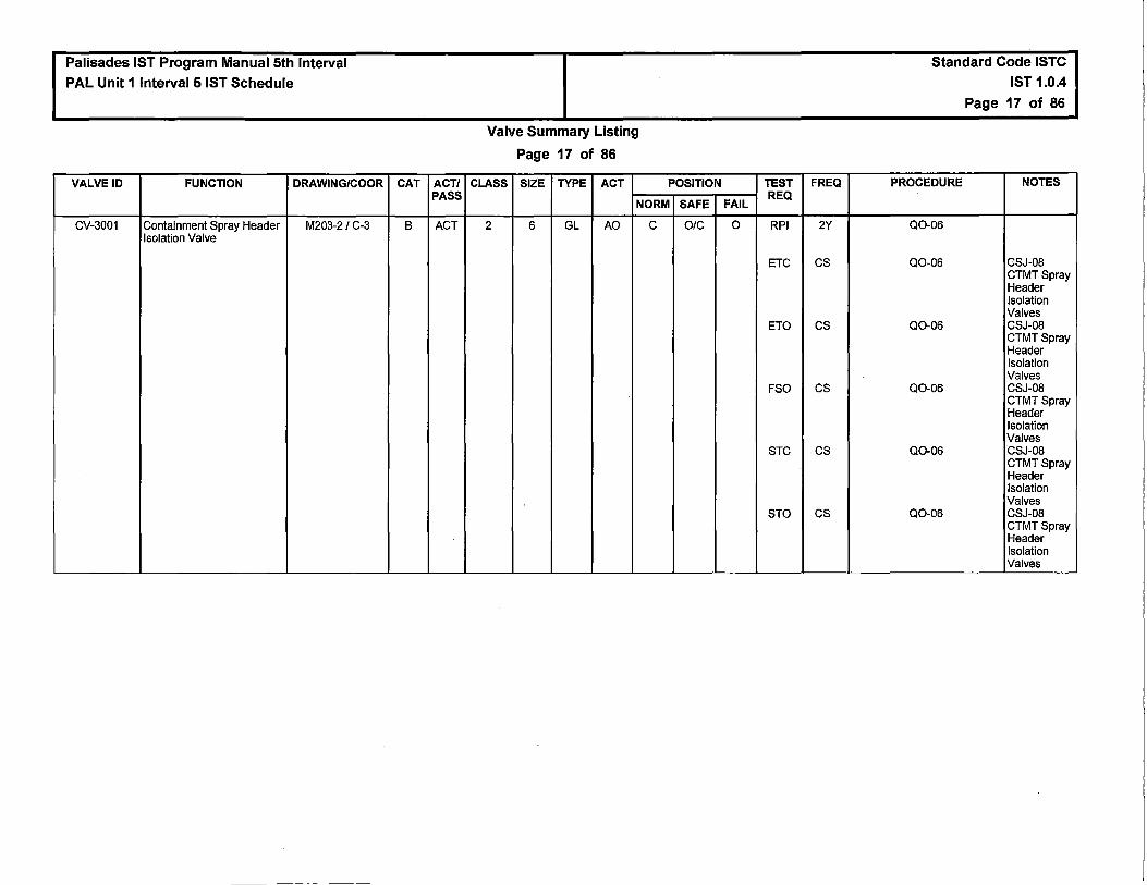
Palisades IST Program Manual 5th Interval PAL Unit 1Interval5 IST Schedule
VALVE ID FUNCTION DRAWING/COOR
CV-3001 Containment Spray Header M203-2/ C-3 Isolation Valve
CAT ACT/ PASS
B ACT
Valve Summary Listing
Page 17 of 86
CLASS SIZE TYPE ACT POSITION
NORM SAFE
2 6 GL AO c O/C
TEST FREQ
FAIL REQ
0 RPI 2Y
ETC cs
ETO cs
FSO cs
STC cs
STO cs
Standard Code ISTC IST 1.0.4
Page 17 of 86
PROCEDURE NOTES
Q0-06
Q0-06 CSJ-08 CTMTSpray Header Isolation Valves
Q0-06 CSJ-08 CTMTSpray Header Isolation Valves
Q0-06 CSJ-08 CTMT Spray Header Isolation Valves
Q0-06 CSJ-08 CTMT Spray Header Isolation Valves
Q0-06 CSJ-08 CTMTSpray Header Isolation Valves

Palisades IST Program Manual 5th Interval PAL Unit 1 Interval 5 IST Schedule
VALVE ID FUNCTION DRAWING/COOR
CV-3002 Containment Spray Header M203-2 / B-3 Isolation Valve
CV-3003 Safety Injection Tank T-82D M203-1 / E-2 Fill And Drain
CV-3004 Safety Injection Tank T-82C M203~1 / E-4 Fill And Drain
CAT ACT/ PASS
B ACT
B PASS
B PASS
Valve Summary Listing
Page 18 of 86
CLASS SIZE TYPE ACT POSITION
NORM SAFE
2 6 GL AO c O/C
2 1 GL AO c c
2 1 GL AO c c
TEST FREQ
FAIL REQ
0 RPI 2Y
ETC cs
ETO cs
FSO cs
STC cs
STO cs
c NTR NR
c NTR NR
Standard Code ISTC IST 1.0.4
Page 18 of 86
PROCEDURE NOTES
Q0-06
Q0-06 CSJ-08 CTMT Spray Header Isolation Valves
Q0-06 CSJ-08 CTMT Spray Header Isolation Valves
Q0-06 CSJ-08 CTMT Spray Header Isolation Valves
Q0-06 CSJ-08 CTMT Spray Header Isolation Valves
Q0-06 CSJ-08 CTMT Spray Header Isolation Valves
NTR
NTR

Palisades IST Program Manual 5th Interval PAL Unit 1 Interval 5 IST Schedule
VALVE ID FUNCTION DRAWING/COOR
CV-3006 LPSI Shutdown CLG Heat M204-1 / A-6 Exchangers Bypass
M0-3007 HPSI To Reactor Coolant M203-2/G-8 Loop ·1A Train 1
M0-3008 LPSI To Reactor Coolant M203-2 / F-7 Loop 1A
M0-3009 HPSI To Reactor Coolant M203-2 / F-7 Loop 18
M0-3010 LPSI To Reactor Coolant M203-2 / D-7 Loop 1B
M0-3011 HPSI To Reactor Coolant M203-2 / D-7 Loop 2A
CAT ACT/ PASS
B ACT
B ACT
B ACT
B ACT
B ACT
B ACT
Valve Summary Listing
Page 19 of 86
CLASS SIZE TYPE ACT POSITION
NORM SAFE
2 12 GL AO ELO O/C
2 2 GL MO c 0
2 6 GL MO c 0
2 2 GL MO c 0
2 6 GL MO c 0
2 2 GL MO c 0
TEST
FAIL REQ
0 ETC
ETO
FSO
STC
STO
FAI RPI
ETO
STO
FAI RPI
ETO
STO
FAI RPI
ETO
STO
FAI RPI
ETO
STO
FAI RPI
ETO
STO
FREQ
cs
cs
cs
cs
cs
2Y
Q
Q
2Y
Q
Q
2Y
Q
Q
2Y
Q
Q
2Y
Q
Q
Standard Code ISTC IST 1.0.4
Page 19 of 86
PROCEDURE NOTES
Q0-43 CSJ-31
Q0-43 CSJ-31
Q0-43 CSJ-31
Q0-43 CSJ-31
Q0-43 CSJ-31
Q0-05
Q0-05
Q0-05
Q0-05
Q0-05
Q0-05
Q0-05
Q0-05
Q0-05
Q0-05
Q0-05
Q0-05
Q0-05
Q0-05
Q0-05

Palisades IST Program Manual 5th Interval PAL Unit 1 Interval 5 IST Schedule
VALVE ID FUNCTION DRAWING/COOR
M0-3012 LPSI To Reactor Coolant M203-2 / C-7 Loop 2A
M0-3013 HPSI To Reactor Coolant M203-2 / 8-7 Loop 28
M0-3014 LPSI To Reactor Coolant M203-2 / A-7 Loop 28
M0-3015 Shutdown Cooling From M204-1 / G-1 Reactor Coolant Loop 2
M0-3016 Shutdown CLG From M204-1 / G-1 Reactor Coolant Loop 2
CV-3018 HPSI train cross connnect M204-1A I G-7 isolation valve
CAT ACT/ PASS
8 ACT
8 ACT
8 ACT
A PASS
A PASS
8 PASS
Valve Summary Listing
Page 20 of 86
CLASS SIZE TYPE ACT POSITION
NORM SAFE
2 6 GL MO c 0
2 2 GL MO c 0
2 6 GL MO c 0
1 12 GA MO ELC c
1 12 GA MO ELG c
2 4 GA AO ELC c
TEST
FAIL REQ
FAI RPI
ETO
STO
FAI RPI
ETO
STO
FAI RPI
ETO
STO
FAI LT
RPI
FAI LT
RPI
c RPI
FREQ
2Y
Q
Q
2Y
Q
Q
2Y
Q
Q
2Y
2Y
2Y
2Y
2Y
Standard Code ISTC IST 1.0.4
Page 20 of 86
PROCEDURE NOTES
Q0-05
Q0-05
Q0-05
Q0-05
Q0-05
Q0-05
Q0-05
Q0-05
Q0-05
Q0-43
Q0-43
Q0-43
Q0-43
Q0-05

Palisades IST Program Manual 5th Interval PAL Unit 1Interval5 IST Schedule
VALVE ID FUNCTION DRAWING/COOR
CV-3025 Shutdown Cooling Heat M204-1 / B-7 Exchanger To LPSI isolation valve
CV-3027 SIRWTank T-58 M204-1 BI G-7 Recirculation
CAT ACT/ PASS
B ACT
A ACT
Valve Summary Listing
Page 21 of 86
CLASS SIZE TYPE ACT POSITION
NORM SAFE
2 10 GL AO ELG O/C
2 6 GA MO 0 O/C
TEST FREQ
FAIL REQ
c ETC Q
ETO Q
FSC Q
STC Q
STO Q
FAI LT 2Y
RPI 2Y
ETC cs
ETO cs
STC cs
STO cs
Standard Code ISTC IST 1.0.4
Page 21 of 86
PROCEDURE NOTES
Q0-42
Q0-42
Q0-42
Q0-42
Q0-42
R0-119
Q0-02
Q0-02 CSJ-10 SIRWTank T-58 Recirculation Valves
Q0-02 C$J-10 SIRWTank T-58 Recirculation Valves
Q0-02 CSJ-10 SIRWTank T-58 Recirculation Valves
Q0-02 CSJ-10 SIRWTank T-58 Recirculation Valves

Palisades IST Program Manual 5th Interval PAL Unit 1 Interval 5 IST Schedule
VALVE ID FUNCTION DRAWING/COOR
CV-3029 Containment Sump M204-1A I E-3 Isolation to East Engineered Safeguards Room
CAT ACT/ PASS
B ACT
Valve Summary Listing
Page 22 of 86
CLASS SIZE TYPE ACT POSITION
NORM SAFE
2 24 GA AO c O/C
TEST FREQ
FAIL REQ
FAI RPI 2Y
ETC cs
ETO cs
STC cs
STO cs
Standard Code ISTC IST 1.0.4
Page 22 of 86
PROCEDURE NOTES
Q0-02
Q0-02 CSJ-14 Containment Sump Isolation Valves
Q0-02 CSJ-14 Containment Sump Isolation Valves
Q0-02 CSJ-14 Containment Sump Isolation Valves
Q0-02 CSJ-14 Containment Sump Isolation Valves
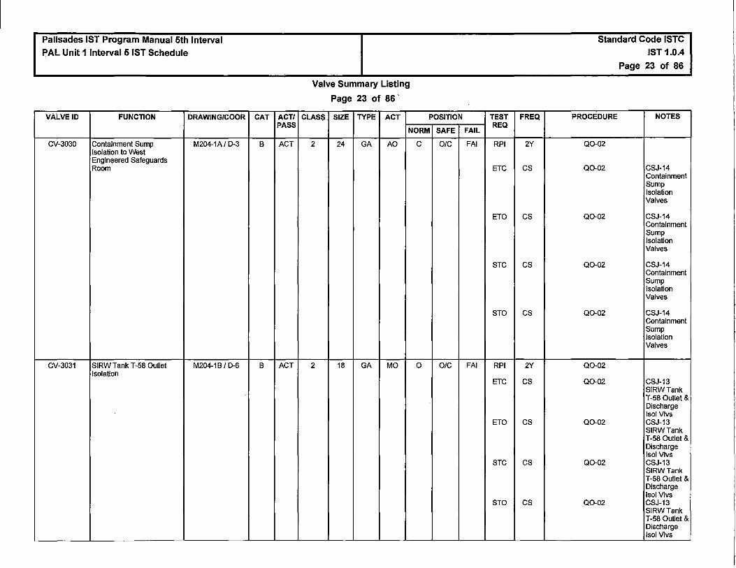
Palisades IST Program Manual 5th Interval PAL Unit 1 Interval 5 IST Schedule
VALVE ID FUNCTION DRAWING/COOR
CV"3030 Containment Sump M204-1A/ D-3 Isolation to West Engin~ered Safeguards Room
CV-3031 SIRW Tank T-58 Outlet M204-1 BI D-6 Isolation
CAT ACT/ PASS
B ACT
B ACT
Valve Summary Listing
Page 23 of 86 '
CLASS SIZE TYPE ACT POSITION
NORM SAFE
2 24 GA AO c OIC
2 18 GA MO 0 O/C
TEST FREQ
FAIL REQ
FAI RPI 2Y
ETC cs
ETO cs
STC cs
STO cs
FAI RPI 2Y
ETC cs
ETO cs
STC cs
STO cs
Standard Code ISTC IST 1.0.4
Page 23 of 86
PROCEDURE NOTES
Q0-02
Q0-02 CSJ-14 Containment Sump Isolation Valves
Q0-02 CSJ-14 Containment Sump Isolation Valves
Q0-02 CSJ-14 Containment Sump Isolation Valves
Q0-02 CSJ-14 Containment Sump Isolation Valves
Q0-02
Q0-02 CSJ-13 SIRWTank T-58 Outlet & Discharge lsol Vlvs
Q0-02 CSJ-13 SIRWTank T-58 Outlet & Discharge lsol Vlvs
Q0-02 CSJ-13 SIRWTank T-58 Outlet & Discharge lsol Vlvs
Q0-02 CSJ-13 SIRWTank T-58 Outlet & Discharge lsol Vlvs

Palisades IST Program Manual 5th Interval PAL Unit 1 Interval 5 IST Schedule
VALVE ID FUNCTION DRAWING/COOR
CV-3036 P-66A to HPSI Train 2 M204-1A/C-6 Isolation Valve
CV-3037 P-66A to HPSJ Train 1 M204-1 A I C-6 Isolation Valve
CV-3038 Safety Inject Tank T-82D M203-1 / D-2 Pressure Control
CV-3039 Safety Injection Tank T-82A M203-1 / E-7 Fill & Drain
CV-3040 Safety Injection Tank T-82A M203-1 / G-6 Nitrogen Fill
M0-3041 Safety Injection Tank T-82A M203-1 / E-6 Outlet Isolation Valve
CV-3042 Safety Injection Tank T-82A M203-1 / D-7 Pressure Control
CV-3043 SI Tank T-828 Fill & Drain M203-1 / E-6 Isolation
CAT ACT/ PASS
B PASS
B PASS
A ACT
B PASS
B PASS
B PASS
A ACT
B PASS
Valve Summary Listing
Page 24 of 86
CLASS SIZE TYPE ACT POSITION
NORM SAFE
2 3 GA AO ELO 0
2 3 GA AO ELC c
1 1 GL AO O/C c
2 1 GL AO c c
2 1 GL AO c c
2 12 GA MO ELO 0
1 1 GL AO O/C c
2 1 GL AO c c
TEST
FAIL REQ
0 RPI
c RPI
c LT
RPI
ETC
FSC
STC
c NTR
c RPI
FAI RPI
c LT
RPI
ETC
FSC
STC
c NTR
FREQ
2Y
2Y
2Y
2Y
Q
Q
Q
NR
2Y
2Y
2Y
2Y
Q
Q
Q
NR
Standard Code ISTC IST 1.0.4
Page 24 of 86
PROCEDURE NOTES
Q0-05
Q0-05
Q0-06
Q0-06
Q0-06
Q0-06
Q0-06
NTR
Q0-06
R0-105
Q0-06
Q0-06
Q0-06
Q0-06
Q0-06
NTR

Palisades IST Program Manual 5th Interval PAL Unit 1.lnterval 5 IST Schedule
VALVE ID FUNCTION DRAWING/COOR
CV-3044 Safety Injection Tank T-828 M203-1 / G-5 Nitrogen Fill
M0-3045 Safety Injection Tank T-828 M203-1 / E-5 Outlet Isolation Valve
CV-3046 Safety Inject Tank T-828 M203-1 / D-5 Pressure Control
-
CV-3047 Safety Inject Tank T-T82C M203-1 / D-4 Pressure Control
CV-3048 Safety Injection TK T-82C M203-1 / G-3 Nitrogen Supply
M0-3049 Safety Injection Tank T-82C M203-1 / E-4 Outlet Isolation Valve
CV-3050 Safety Injection Tank T-820 M203-1 / G-2 Nitrogen Fill
CAT ACT/ PASS
8 PASS
8 PASS
A ACT
A ACT
8 PASS
8 PASS
8 PASS
Valve Summary Listing
Page 25 of 86
CLASS SIZE TYPE ACT POSITION
NORM SAFE
2 1 GL AO c c
2 12 GA MO ELO 0
1 1 GL AO O/C c
1 1 GL AO O/C c
2 1 GL AO c c
2 12 GA MO ELO 0
2 1 GL AO c c
TEST
FAIL REQ
c RPI
FAI RPI
c LT
RPI
ETC
FSC
STC
c LT
RPI
ETC
FSC
STC
c RPI
FAI RPI
c RPI
FREQ
2Y
2Y
2Y
2Y
Q
Q
Q
2Y
2Y
Q
Q
Q
2Y
2Y
2Y
Standard Code ISTC IST 1.0.4
Page 25 of 86
PROCEDURE NOTES
Q0-06
R0-105
Q0-06
Q0-06
Q0-06
Q0-06
Q0-06
Q0-06
Q0-06
Q0-06
Q0-06
Q0-06
Q0-06
R0-105
Q0-06

Palisades IST Program Manual 5th Interval PAL Unit 1 Interval 5 IST Schedule
VALVE ID FUNCTION DRAWING/COOR
CV-3051 Safety Injection Tank T-820 M203-1 / F-2 Vent Valve
M0-3052 Safety Injection Tank T-820 M203-1 / E-2 Discharge Isolation Valve
CV-3055 Shutdown Cooling Inlet To M204-1 / C-5 Shutdown HX
CV-3056 SIRWTank T-58 M204-18 I G-7 Recirculation Shutoff
CAT ACT/ PASS
B PASS
B PASS
B ACT
A ACT
Valve Summary Listing
Page 26 of 86
CLASS SIZE TYPE ACT POSITION
NORM SAFE
2 1 GL AO c c
2 12 GA MO ELO 0
2 12 GA AO ELG c
2 6 GA MO 0 O/C
TEST FREQ
FAIL REQ
c RPI 2Y
FAI RPI 2Y
c RPI 2Y
ETC a FSC a STC a
FAI LT 2Y
RPI 2Y
ETC cs
ETO cs
STC cs
STO cs
Standard Code ISTC
IST 1.0.4
Page 26 of 86
PROCEDURE NOTES
Q0-06
R0-105
Q0-42
Q0-42
Q0-42
Q0-42
R0-119
Q0-02
Q0-02 CSJ-10 SIRWTank T-58 Recirculation Valves
Q0-02 CSJ-10 SIRWTank T-58 Recirculation Valves
Q0-02 CSJ-10 SIRWTank T-58 Recirculation Valves
Q0-02 CSJ-10 SIRWTank T-58 Recirculation Valves

Palisades IST Program Manual 5th Interval PAL Unit 1 Interval 5 IST Schedule
VALVE ID FUNCTION DRAWING/COOR
CV-3057 SIRWTank T-58 Discharge M204-1B I C-6 Shutoff Valve
CV-3059 P-668 to HPSI Train 1 M204-1A I G-6 Isolation Valve
M0-3062 HPSI Train 2 to Reactor M203-2 / 8-7 Coolent Loop 28
CV-3063 Safety Injection Tank T-82C M203-1 / F-4 Vent Valve
M0-3064 HPSI Train 2 to Reactor M203-2 / C-7 Coolant Loop 2A
CV-3065 Safety Injection Tank T-828 M203-1 / F-5 Vent Valve
CAT ACT/ PASS
8 ACT
8 PASS
8 ACT
8 PASS
8 ACT
8 PASS
Valve Summary Listing
Page 27 of 86
CLASS SIZE TYPE ACT POSITiON
NORM SAFE
2 18 GA MO 0 O/C
2 4 GA AO ELO 0
2 2 GL MO c 0
2 1 GL AO c c
2 2 GL MO c 0
2 1 GL AO c c
TEST
FAIL REQ
FAI RPI·
ETC
ETO
STC
STO
0 RPI
FAI RPI
ETO
STO
c RPI
FAI RPI
ETO
STO
c RPI
FREQ
2Y
cs
cs
cs
cs
2Y
2Y
a a
2Y
2Y
a
a
2Y
Standard Code ISTC IST 1.0.4
Page 27 of 86
PROCEDURE NOTES
Q0-02
Q0-02 CSJ-13 SIRWTank T-58 Outlet & Discharge lsol Vlvs
Q0-02 CSJ-13 SIRWTank T-58 Outlet & Discharge Isol Vlvs
Q0-02 CSJ-13 SIRWTank T-58 Outlet & Discharge lsol Vlvs
Q0-02 CSJ-13 SIRWTank T-58 Outlet & Discharge lsol Vlvs
Q0-05
Q0-05
Q0-05
Q0-05
Q0-06
Q0-05
Q0-05
Q0-05
Q0-06

Palisades IST Program Manual 5th Interval PAL Unit 1 Interval 5 IST Schedule
VALVE ID FUNCTION DRAWING/COOR
M0-3066 HPSI Train 2 to Reactor M203-2 / E-7 Coolant Loop 1 B
CV-3067 Safety Injection Tank T-82A M203-1/ F-7 Vent Valve
M0-3068 HPSI Train 2 to Reactor M203-2/ G-7 Coolant Loop 1A
CV-3069 SI Tank Drain To Primary M203-1 / C-7 System Drain Tank
CV-3070 HPSI Pump P-668 M204-1 / H-6 Subcooling Isolation Valve
CAT ACT/ PASS
B ACT
B PASS
B ACT
B PASS
B ACT
Valve Summary Listing
Page 28 of 86
CLASS SIZE TYPE ACT POSITION
NORM SAFE
2 2 GL MO c 0
2 1 GL AO c c
2 2 GL MO c 0
NC 2 GL AO O/C c
2 4 GA AO c O/C
TEST
FAIL REQ
FAI RPI
ETO
STO
c RPI
FAI RPI
ETO
STO
c RPI
c RPI
ETC
ETO
FSC
STC
STO
FREQ
2Y
Q
Q
2Y
2Y
Q
a
2Y
2Y
Q
Q
Q
Q
a
Standard Code ISTC IST 1.0.4
Page 28 of 86
PROCEDURE NOTES
Q0-05
Q0-05
Q0-05
Q0-06
Q0-05
Q0-05
Q0-05
Q0-06
Q0-05
Q0-05
Q0-05
Q0-05
Q0-05
Q0-05

Palisades IST Program Manual 5th Interval
PAL Unit 1 Interval 5 IST Schedule
VALVE ID FUNCTION DRAWING/COOR
CV-3071 High Press Safety Inject P- M204-1A I B-4 66A Subcooling
M0-3072 From Charging PP Line to M204-1A/C-8 SI Test Line lsol
M0-3080 HPSI Hot Leg Injection M203-2 / F-5 Mode Select Valve
CAT ACT/ PASS
B ACT
B ACT
B ACT
Valve Summary Listing
Page 29 of 86
CLASS SIZE TYPE ACT POSITION
NORM SAFE
2 4 GA AO c DIC
2 2 GL MO ELC c
2 6 GA MO ELO O/C
TEST
FAIL REQ
c RPI
ETC
ETO
FSC
STC
STO
FAI RPI
ETC
STC
FAI RPI
ETC
ETO
STC
STO
FREQ
2Y
Q
Q
Q
Q
Q
2Y
Q
Q
2Y
Q
Q
Q
Q
Standard Code ISTC IST 1.0.4
Page 29 of 86
PROCEDURE NOTES
Q0-05
Q0-05
Q0-05
Q0-05
Q0-05
Q0-05
Q0-06
Q0-06
QQ,06
Q0-06
Q0-05
Q0-05
Q0-05
Q0-05
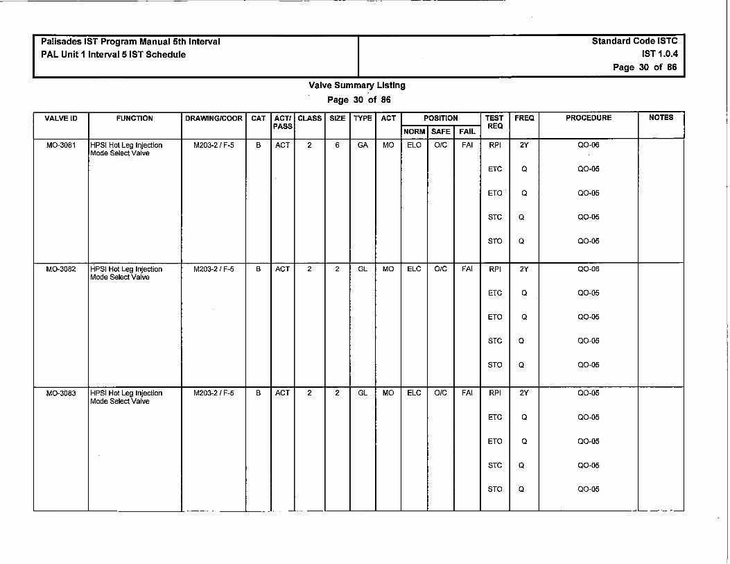
Palisades IST Program Manual 5th Interval
PAL Unit 1 Interval 5 IST Schedule
VALVE ID FUNCTION DRAWING/COOR
M0-3081 HPSI Hot Leg Injection M203-2 / F-5 Mode Select Valve
M0-3082 HPSI Hot Leg Injection M203-2 / F-5 Mode Select Valve
M0-3083 HPSI Hot Leg Injection M203-2 / F-5 Mode Select Valve
CAT ACT/ PASS
B ACT
B ACT
B ACT
Valve Summary Listing
Page 30 of 86
CLASS SIZE TYPE ACT POSITION
NORM SAFE
2 6 GA MO ELO OIC
2 2 GL MO ELC O/C
2 2 GL MO ELC O/C
TEST
FAIL REQ
FAI RPI
ETC
ETO
STC
STO
FAI RPI
ETC
ETO
STC
STO
FAI RPI
ETC
ETO
STC
STO
FREQ
2Y
Q
Q
Q
Q
2Y
Q
Q
Q
Q
2Y
Q
Q
Q
Q
Standard Code ISTC IST 1.0.4
Page 30 of 86
PROCEDURE NOTES
Q0-06
Q0-05
Q0-05
Q0-05
Q0-05
Q0-06
Q0-05
Q0-05
Q0-05
Q0-05
Q0-05
Q0-05
Q0-05
Q0-05
Q0-05

Palisades IST Program Manual 5th Interval
PAL Unit 1 Interval 5 IST Schedule
VALVE ID FUNCTION DRAWING/COOR
CV-3084 HPSI Hot Leg Drain M201-1/8-3 Isolation
RV-3113 Safety Injection Tank T-82A M203-1 I G-7 Relief Valve
RV-3128 Safety Injection Tank T-828 M203-1 I G-5 Relief Valve
RV-3143 Safety Injection Tank T-82C M203-1 I G-4 Relief Valve
RV-3158 Safety Injection Tank T-820 M203-1 I G-2 Relief Valve
RV-3162 Low Pressure Injection M203-2 I E-6 Relief Valve
RV-3164 Shutdown Cooling Relief M204-1 IE-1
RV-3165 High Press Safety Injection M203-21 H-6 Relief Valve Train 1
M0-3189 LPSI Pump P-678 Inlet M204-1A I F-4 from SIRW Tank
M0-3190 LPSI pump P-678 M204-1 I D-2 Shutdown Cooling inlet
M0-3198 LPSI Pump P-67A Inlet M204-1A I E-4 from SIRW Tank
CAT ACT/ PASS
8 ACT
c ACT
c ACT
c ACT
c ACT
c ACT
c ACT
c ACT
8 PASS
8 ACT
8 PASS
Valve Summary Listing
Page 31 of 86
CLASS SIZE TYPE ACT POSITION
NORM SAFE
1 1 GL AO c c
2 1 RV SA c OIC
2 1 RV SA c OIC
2 1 RV SA c OIC ·
2 1 RV SA c OIC
2 2 RV SA c OIC
2 1.5 RV SA c OIC
2 0.5 RV SA c OIC
2 14 GA MO ELO 0
2 14 GA MO ELG OIC
2 14 GA MO ELO 0
TEST
FAIL REQ
c RPI
ETC
FSC
STC
NIA RV
NIA RV
NIA RV
NIA RV
NIA RV
NIA RV
NIA RV
FAI RPI
FAI RPI
ETC
ETO
STC
STO
FAI RPI
FREQ
2Y
Q
Q
Q
10Y
10Y
10Y
10Y
10Y
10Y
10Y
2Y
2Y
Q
Q
Q
Q
2Y
Standard Code ISTC IST 1.0.4
Page 31 of 86
PROCEDURE NOTES
Q0-06
Q0-06
Q0-06
Q0-06
RT-116
RT-116
RT-116
RT-116
RT-116
RT-116
RT-116
Q0-05
Q0-05
Q0-05
Q0-05
Q0-05
Q0-05
Q0-05

Palisades IST Program Manual 5th Interval PAL Unit 1 Interval 5 IST Schedule
VALVE ID FUNCTION DRAWING/COOR
M0-3199 LPSI Pump P-67A Inlet M204-1A I F-4 from Shutdown Cooling
CV-3212 Shutdown Cooling Heat M204-1/8-6 Exchanger E-608 Inlet Valve
CV-3213 Shutdown Cooling Heat M204-1 / D-6 Exchanger E-608 Outlet Valve
CV-3223 Shutdown Cooling Heat M204-1 / G-6 Exchanger E-60A Inlet Valve
CV-3224 Shutdown Cooling Heat M204-1 / E-6 Exchanger E-60A Outlet Valve
RV-3264 HP Safety Injection Relief- M203-2 /G-6 Train 2
RV-3266 HP Pumps Discharge M204-1 A I H-6 Header Relief
RV-3267 P-66A Discharge Relief M204-1A/ C-6
MV-ES113 CSTOCVC PCS M203-2 /C-2 CLEANUP HEADER ISOL VALVE
CK-ES3101 PCS Loop Check Valve M203-1/8-8 (Loop 1A)
CAT
8
8
8
8
8
c
c
c
8
A/C
ACT/ PASS
ACT
PASS
PASS
PASS
PASS
ACT
ACT
ACT
PASS
ACT
Valve Summary Listing
Page 32 of 86
CLASS SIZE TYPE ACT POSITION
NORM SAFE
2 14 GA MO ELC O/C
2 10 GA MO ELO 0
2 10 GA MO ELO 0
2 10 GA MO ELO 0
2 10 GA MO ELO 0
2 0.5 RV SA c OIC
2 0.5 RV SA c O/C
2 0.5 RV SA c O/C
2 2 PLG H c c
1 12 CK SA c O/C
TEST
FAIL REQ
FAI RPI
ETC
ETO
STC
STO
FAI RPI
FAI RPI
FAI · RPI
FAI RPI
N/A RV
N/A RV
N/A RV
N/A NTR
NIA LT
eve
cvo
FREQ
2Y
Q
Q
Q
Q
2Y
2Y
2Y
2Y
10Y
10Y
10Y
NR
2Y
Q
R
Standard Code ISTC
IST 1.0.4
Page 32 of 86
PROCEDURE NOTES
Q0-05
Q0-05
Q0-05
Q0-05
Q0-05
Q0-42
Q0-42
Q0-42
Q0-42
RT-116
RT-116
RT-116
NTR
S0-9
DW0-1
R0-105 ROJ-07 ESS PCS Loop Check Valves (Loop 1A. 18, 2A&28)

Palisades IST Program Manual 5th Interval
PAL Unit 1 Interval 5 IST Schedule
VALVE ID· FUNCTION DRAWING/COOR
CK-ES3102 Safety Injection Tank T-82A M203-1 / D-7 Check Valve
CK-ES3103 Low Pressure Injection M203-2 / F-8 Check Valve
CK-ES3104 High Pressure Injection M203-2/G-8 Check Valve
CK-ES3116 PCS Loop Check Valve M203-1/8-7 (Loop 18)
CAT ACT/ PASS
A/C ACT
A/C ACT
A/C ACT
A/C ACT
Valve Summary Listing
Page 33 of 86
CLASS SIZE TYPE ACT POSITION
NORM SAFE
1 12 CK SA c O/C
~
1 6 CK SA c O/C
1 2 CK SA c O/C
1 12 CK SA c O/C
TEST FREQ
FAIL REQ
N/A LT 2Y
eve Q
cvo R
NIA LT 2Y
eve cs
cvo cs
N/A LT 2Y
eve R
cvo R
N/A LT 2Y
eve Q
cvo R
Standard Code ISTC IST 1.0.4
Page 33 of 86
PROCEDURE NOTES
SH0-1
SH0-1
R0-105 ROJ-06 ESS Safety Injection Tanks T-82A, 8, C&D Check Valves
S0-9
Q0-32 CSJ-39 Low Pressure Injection Check Valves
Q0-088 CSJ-39 Low Pressure Injection Check Valves
S0-9
S0-9 ROJ-02 High Pressure Injection Check Valves
R0-65 ROJ-02 High Pressure Injection Check Valves
S0-9
DW0-1
R0-105 ROJ-07 ESS PCS Loop Check Valves (Loop 1A. 18, 2A&28)
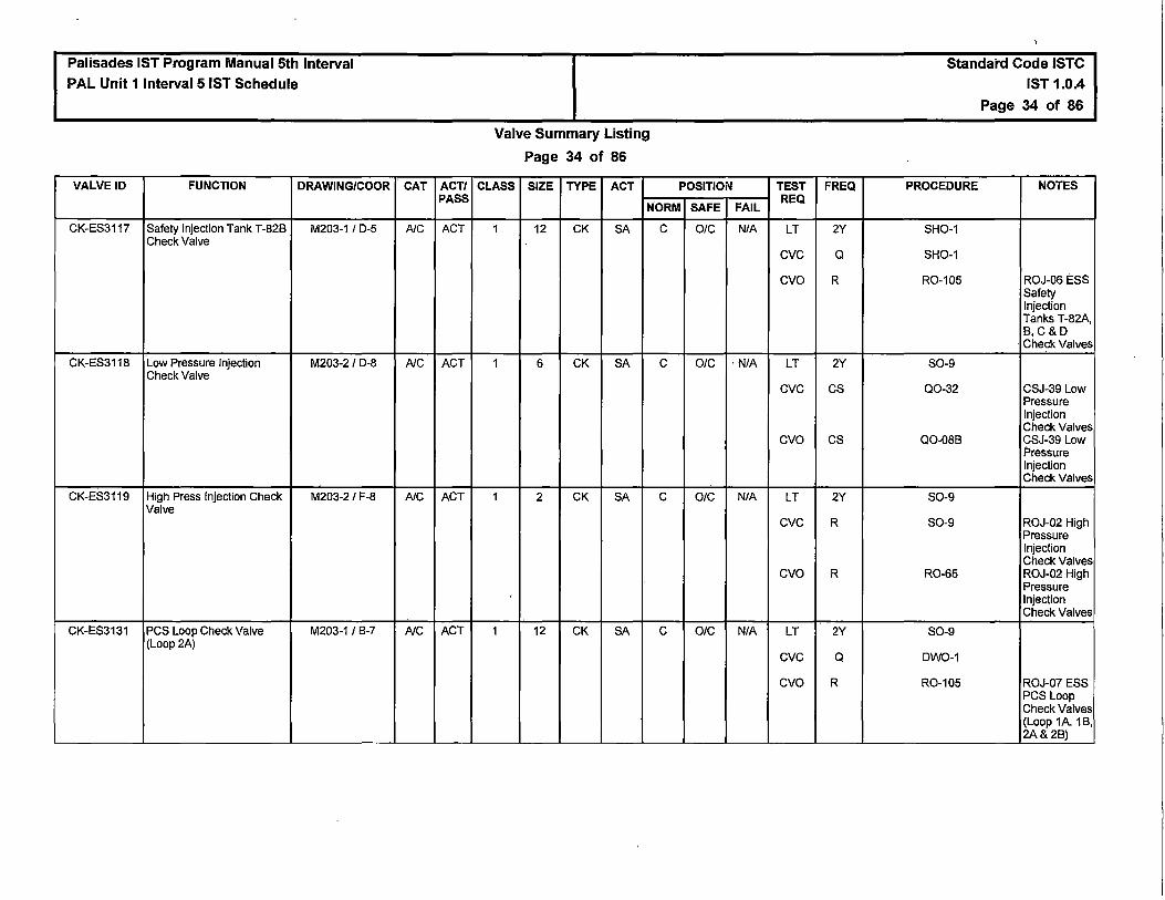
Palisades IST Program Manual 5th Interval PAL Unit 1 Interval 5 IST Schedule
VALVE ID FUNCTION DRAWING/COOR
CK-ES3117 Safety Injection Tank T-828 M203-1 I D-5 Check Valve
CK-ES3118 Low Pressure Injection M203-2 / D-8 Check Valve
CK-ES3119 High Press Injection Check M203-2 / F-8 Valve
CK-ES3131 PCS Loop Check Valve M203-1/8-7 (Loop 2A)
CAT ACT/ PASS
A/C ACT
A/C ACT
AIC ACT
A/C ACT
Valve Summary Listing
Page 34 of 86
CLASS SIZE TYPE ACT POSITION
NORM SAFE FAIL
1 12 CK SA c O/C N/A
1 6 CK SA c O/C · N/A
1 2 CK SA c O/C N/A
1 12 CK SA c 0/C NIA
TEST FREQ REQ
LT 2Y
eve a cvo R
LT 2Y
eve cs
cvo cs
LT 2Y
eve R
cvo R
LT 2Y
eve a cvo R
Standard Code ISTC IST 1.0.4
Page 34 of 86
PROCEDURE NOTES
SH0-1
SH0-1
R0-105 ROJ-06 ESS Safety Injection Tanks T-82A, 8,C&D Check Valves
S0-9
Q0-32 CSJ-39 Low Pressure Injection Check Valves
Q0-088 CSJ-39 Low Pressure Injection Check Valves
S0-9
S0-9 ROJ-02 High Pressure Injection Check Valves
R0-65 ROJ-02 High Pressure Injection Check Valves
S0-9
DW0-1
R0-105 ROJ-07 ESS PCS Loop Check Valves (Loop 1A. 18, 2A&28)

Palisades IST Program Manual 5th Interval PAL Unit 1 Interval 5 IST Schedule
VALVE ID FUNCTION DRAWING/COOR
CK-ES3132 Safety Injection Tank T-82C M203-1 / D-3 Check Valve
CK-ES3133 Low Pressure Injection M203-2 / C-8 Check Valve
CK-ES3134 High Pressure Injection M203-2 / D-8 Check Valve
CK-ES3146 PCS Loop Check Valve M203-1 I 8-7 (Loop 28)
CAT ACT/ PASS
NC ACT
NC ACT
NC ACT
NC ACT
Valve Summary Listing
Page 35 of 86
CLASS SIZE TYPE ACT POSITION
NORM SAFE
1 12 CK SA c O/C
1 6 CK SA c O/C
1 2 CK SA c O/C
1 12 CK SA c O/C
TEST FREQ
FAIL REQ
N/A LT 2Y
eve Q
cvo R
NIA LT 2Y
eve cs
cvo cs
N/A LT 2Y
eve R
cvo R
NIA LT 2Y
eve Q
cvo R
Standard Code ISTC IST 1.0.4
Page 35 of 86
PROCEDURE NOTES
SH0-1
SH0-1
R0-105 ROJ-06 ESS Safety Injection Tanks T-82A, 8, C&D Check Valves
S0-9
Q0-32 CSJ-39 Low Pressure Injection Check Valves
Q0-088 CSJ-39 Low Pressure Injection Check Valves
S0-9
S0-9 ROJ-02 High Pressure Injection Check Valves
R0-65 ROJ-02 High Pressure Injection Check Valves
S0-9
DW0-1
R0-105 ROJ-07 ESS PCS Loop Check Valves (Loop 1A. 18, 2A&28)

Palisades IST Program Manual 5th Interval PAL Unit 1 Interval 5 IST Schedule
VALVE ID FUNCTION DRAWING/COOR
CK-ES3147 Safety Injection Tank T-820 M203-1 / D-2 Check Valve
CK-ES3148 Low Pressure Injection M203-2 I A-8 Check Valve
CK-ES3149 High Pressure Injection M203-2 / 8-8 Check Valve
CK-ES3166 Containment Sump Outlet M204-1A I D-3 Check Valve West
CK-ES3168 HPSI Pump P-668 Intake M204-181C-7 Check
CAT ACT/ PASS
A/C ACT
A/C ACT
A/C ACT
c ACT
c ACT
Valve Summary Listing
Page 36 of 86
CLASS SIZE TYPE ACT POSITION
NORM SAFE
1 12 CK SA c O/C
1 6 CK SA c OIG
1 2 CK SA c OIG
2 24 CK SA c OIG
2 8 CK SA c OIG
TEST FREQ
FAIL REQ
NIA LT 2Y
eve Q
cvo R
NIA LT 2Y
eve cs
cvo cs
NIA LT 2Y
eve R
cvo R
NIA eve CM
cvo CM
NIA eve CM
cvo CM
Standard Code ISTC IST 1.0.4
Page 36 of 86
PROCEDURE NOTES
SH0-1
SH0-1
R0-105 ROJ-06 ESS Safety Injection Tanks T-82A, 8, C&D Check Valves
S0-9
Q0-32 CSJ-39 Low Pressure Injection Check Valves
Q0-088 CSJ-39 Low Pressure Injection Check Valves
S0-9
S0-9 ROJ-02 High Pressure Injection Check Valves
R0-65 ROJ-02 High Pressure Injection Check Valves
CMJ-ESS-C-19 CMJ-ESS-C-19
CMJ-ESS-C-19 CMJ-ESS-C-19
CMJ-ESS-S-03 CMJ-ESS-S-03
CMJ-ESS-S-03 CMJ-ESS-S-03

.)
Palisades IST Program Manual 5th Interval PAL Unit 1 Interval 5 IST Schedule
VALVE ID FUNCTION DRAWING/COOR
CK-ES3177 High Pressure Pump P-66B M204-1 / G-4 Discharge Check Valve
CK-ES3181 Containment Sump Outlet M204-1A I E-3 Check Valve East
CK-ES3183 HPSI Pump P-66A Intake M204-1A/C-4 Check Valve
CK-ES3186 HPSI Pump P-66A M204-1A/C-6 Discharge Check Valve
CK-ES3192 Low Press Pump P-67B M204-1 / E-4 Discharge Check Valve
CAT ACT/ PASS
c ACT
c ACT
c ACT
-
c ACT
c ACT
Valve Summary Listing
Page 37 of 86
CLASS SIZE TYPE ACT POSITION
NORM SAFE
2 3 CK SA c 0
2 24 CK SA c O/C
2 6 CK SA c O/C
2 3 CK SA c 0
2 10 CK SA c O/C
TEST FREQ
FAIL REQ
N/A BOC CM
cvo CM
N/A eve CM
cvo CM
N/A eve CM
cvo CM
NIA BOC CM
cvo CM
NIA eve cs
cvo cs
Standard Code ISTC IST 1.0.4
Page 37 of 86
PROCEDURE NOTES
CMJ-ESS-S-05 CMJ-ESS-S-05
CMJ-ESS-S-05 CMJ-ESS-S-05
CMJ-ESS-C-19 CMJ-ESS-C-19
CMJ-ESS-C-19 CMJ-ESS-C-19
CMJ-ESS-S-03 CMJ-ESS-S-03
CMJ-ESS-S-03 CMJ-ESS-S-03
CMJ-ESS-S-05 CMJ-ESS-S-05
CMJ-ESS-S-05 CMJ-ESS-S-05
Q0-08B CSJ-38 Low Pressure Pump P-67A &B Discharge Check Valves
Q0-08B CSJ-38 Low Pressure Pump P-67A &B Discharge Check Valves

Palisades IST Program Manual 5th Interval
PAL Unit 1 Interval 5 IST Schedule
VALVE ID FUNCTION DRAWING/COOR
CK-ES3201 LPSI Pump P-67A M204-1A I E-6 Discharge Check
CK-ES3208 Containment Spray Pump M204-1 / D-4 P-54C Discharge Check Valve
CK-ES3216 Containment Spray Check M203-2 / 8-3 Valve
CK-ES3220 Containment Spray Pump M204-1 / 8-4 P-548 Discharge Check Valve
CAT ACT/ PASS
c ACT
c ACT
c ACT
c ACT
Valve Summary Listing
Page 38 of 86
CLASS SIZE TYPE ACT POSITION
NORM SAFE
2 10 CK SA c O/C
2 8 CK SA c O/C
2 8 CK SA c OIC
2 8 CK SA c O/C
TEST FREQ
FAIL REQ
N/A eve cs
cvo cs
N/A eve R
cvo R
N/A eve CM
cvo CM
N/A eve R
cvo R
Standard Code ISTC IST 1.0.4
Page 38 of 86
PROCEDURE NOTES
Q0-088 CSJ-38 Low Pressure Pump P-67A &8 Discharge Check Valves
Q0-088 CSJ-38 Low Pressure Pump P-67A &8 Discharge Check Valves
R0-98 ROJ-08 ESS Containment Spray Pump P-54A, 8 &C DSCH CK VLVS
R0-98 ROJ-08 ESS Containment Spray Pump P-54A, 8 &C DSCH CK VLVS
CMJ-ESS-S-16 CMJ-ESS-S-16
CMJ-ESS-S-16 CMJ-ESS-S-16
R0-98 ROJ-08 ESS Containment Spray Pump P-54A, 8 &C DSCH CK VLVS
R0-98 ROJ-08 ESS Containment Spray Pump P-54A, 8 &C DSCH CK VLVS

Palisades IST Program Manual 5th Interval PAL Unit 1 Interval 5 IST Schedule
VALVE ID FUNCTION DRAWING/COOR
CK-ES3226 Containment Spray Check M203-2 / C-3 Valve
CK-ES3230 Containment Spray Pump M204-1A I D-5 P-54A Discharge Check Valve
CK-ES3233 Pump P-67 A Miniflow M204-1A I F-4 Check Valve
MV-ES3234 Safety Injection Tank Drain M204-1 / H-8 Line Isolation Valve
MV-ES3234A Safety Injection Tank Drain M204-1 I H-8 Line Isolation Valve
CK-ES3239 SIRW Tank T-58 Discharge M204-1 BI D-6 Check (Trairi B)
CK-ES3240 SIRWTank T-58 Discharge M204-1 BI D-6 Check (Train A)
CAT ACT/ PASS
c ACT
c ACT
c ACT
A PASS
A PASS
c ACT
c ACT
Valve Summary Listing
Page 39 of 86
CLASS SIZE TYPE ACT POSITION
NORM SAFE
2 8 CK SA c O/C
2 8 CK SA c OIG
2 3 CK SA c OIG
2 2 GA H c c
2 2 GA H c c
2 18 CK SA c OIG
2 18 CK SA c O/C
TEST FREQ
FAIL REQ
N/A eve CM
cvo CM
NIA eve R
cvo R
NIA eve CM
cvo CM
NIA LTJ AppJ
NIA LTJ AppJ
NIA eve CM
cvo CM
NIA eve CM
cvo CM
Standard Code ISTC
IST 1.0.4
Page 39 of 86
PROCEDURE NOTES
CMJ-ESS-S-16 CMJ-ESS-S-16
CMJ-ESS-S-16 CMJ-ESS-S-16
R0-98 ROJ-08 ESS Containment Spray Pump P-54A, B &C DSCH CK VLVS
R0-98 ROJ-08 ESS Containment Spray Pump P-54A, B & C DSCH CK VLVS
CMJ-ESS-S-17 CMJ-ESS-S-17
CMJ-ESS-S-17 CMJ-ESS-S-17
R0-032-33
R0-032-33
CMJ-ESS-S-01 CMJ-ESS-S-01
CMJ-ESS-S-01 CMJ-ESS-S-01
CMJ-ESS-S-01 CMJ-ESS-S-01
CMJ-ESS-S-01 CMJ-ESS-S-01
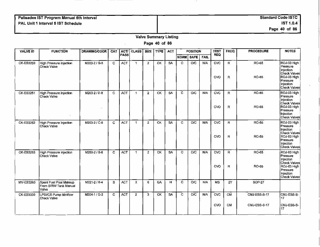
Palisades IST Program Manual 5th Interval PAL Unit 1 Interval 5 IST Schedule
VALVE ID FUNCTION DRAWING/COOR
CK-ES3250 High Pressure Injection M203-2/ G-8 Check Valve
CK-ES3251 High Pressure Injection M203-2 / E-8 Check Valve
CK-ES3252 High Pressure Injection M203-2 / C-8 Check Valve
CK-ES3253 High Pressure Injection M203-2 / B-8 Check Valve
MV-ES3263 Spent Fuel Pool Makeup M221-2 / B-4 From SIRW Tank Manual Valve
CK-ES3330 LPSl/CS Pump Miniflow M204-1 / G-2 Check Valve
CAT ACT/ PASS
c ACT
c ACT
c ACT
c ACT
B ACT
c ACT
Valve Summary Listing
Page 40 of 86
CLASS SIZE TYPE ACT POSITION
NORM SAFE
1 2 CK SA c O/C
1 2 CK SA c O/C
1 2 CK SA c OIC
1 2 CK SA c O/C
2 6 GA H c OIC
2 3 CK SA c O/C
TEST FREQ
FAIL REQ
N/A eve R
cvo R
N/A eve R
cvo R
N/A eve R
cvo R
N/A eve R
cvo R
N/A MS 2Y
NIA eve CM
cvo CM
Standard Code ISTC IST 1.0.4
Page 40 of 86
PROCEDURE NOTES
R0-65 ROJ-03 High Pressure Injection Check Valves
R0-65 ROJ-03 High Pressure Injection Check Valves
R0-65 ROJ-03 High Pressure Injection Check Valves
R0-65 ROJ-03 High Pressure Injection Check Valves
R0-65 ROJ-03 High Pressure Injection Check Valves
R0-65 ROJ-03 High Pressure Injection Check Valves
R0-65 ROJ-03 High Pressure Injection Check Valves
R0-65 ROJ-03 High Pressure Injection Check Valves
SOP-27
CMJ-ESS-S-17 CMJ-ESS-S-17
CMJ-ESS-S-17 CMJ-ESS-S-17

Palisades IST Program Manual 5th Interval PAL Unit 1 Interval 5 IST Schedule
VALVE ID FUNCTION DRAWING/COOR
CK-ES3331 HPSl/LPSI Pump Miniflow M204-1 / H-2 Check Valve
CK-ES3332 HPSl/LPSl/CS Pump M204-1 I H-2 Miniflow Check Valve
CK-ES3339 HPSI Pump P-66B Miniflow M204-1 / G-3 Check
CK-ES3340 Pump P-66A Miniflow M204-1 A I C-4 Check Valve
CK-ES3408 Hot .Leg Injection Check M203-2 / E-5 Valve
CK-ES3409 Hot Leg Injection Check M203-2 / E-5 Valve
CK-ES3410 HPSI Hot Leg Injection M201-1 /C-3 Check Valve
CAT ACT/ PASS
c ACT
c ACT
c ACT
c ACT
c ACT
c ACT
c ACT
Valve Summary Listing
Page 41 of 86
CLASS SIZE TYPE ACT POSITION
NORM SAFE
2 4 CK SA c 0
2 4 CK SA c 0
2 2 CK SA c O/C
2 2 CK SA c O/C
1 2 CK SA c O/C
1 2 CK SA c O/C
1 2 CK SA c O/C
TEST FREQ
FAIL REQ
N/A BOC CM
cvo CM
N/A BOC CM
cvo CM
N/A eve CM
cvo CM
N/A eve CM
cvo CM
N/A eve R
cvo R
N/A eve R
cvo R
NIA eve Q
cvo R
Standard Code ISTC IST 1.0.4
Page 41 of 86
PROCEDURE NOTES
CMJ-ESS-S-18 CMJ-ESS-S-18
CMJ-ESS-S-18 CMJ-ESS-S-18
CMJ-ESS-S-18 CMJ-ESS-S-18
CMJ-ESS-S-18 CMJ-ESS-S-18
CMJ-ESS-S-06 CMJ-ESS-S-06
CMJ-ESS-S-06 CMJ-ESS-S-06
CMJ-ESS-S-06 CMJ-ESS-S-06
CMJ-ESS-S-06 CMJ-ESS-S-06
R0-147 ROJ-04 ESS Hot Leg Injection Check Valves
R0-147 ROJ-04 ESS Hot Leg Injection Check Valves
R0-147 ROJ-04 ESS Hot Leg Injection Check Valves
R0-147 ROJ-04 ESS Hot Leg Injection Check Valves
Q0-19
R0-147 ROJ-01 HPSI Hot Leg Injection Check Valve

Palisades IST Program Manual 5th Interval PAL Unit 1 Interval 5 IST Schedule
VALVE ID FUNCTION DRAWING/COOR
CK-ES3411 HPSI P-66A Discharge M204-1A/ C-6 Check Valve
MV-FP130 Critical SW Header B & Fire M213 / H-1 SYS Crosstie
MV-FP131 Critical SW Header A & Fire M213 / G-4 SYS Crosstie
RV-0521A Steam Supply To Auxiliary M205-2 / E-2 Feed Pump
RV-05216 Steam Supply To Auxiliary M205-2 / E-1 Feed Pump
CV-0727 Auxiliary Feedwater Flow to M207-2/ G-4 Steam Generator E-50B from P-8A and P-8B
CAT
c
B
B
c
c
B
ACT/ PASS
ACT
ACT
ACT
ACT
ACT
ACT
Valve Summary Listing
Page 42 of 86
CLASS SIZE TYPE ACT POSITION
NORM SAFE
2 3 CK SA c 0
3 12 GA H c O/C
3 12 GA H c O/C
3 4 RV SA c O/C
3 4 RV SA c O/C
3 4 GL AO c O/C
TEST
FAIL REQ
N/A BOC
cvo
NIA MS
N/A MS
N/A RV
N/A RV
0 RPI
ETC
ETO
FSO
STC
STO
FREQ
CM
CM
2Y
2Y
10Y
10Y
2Y
Q
Q
Q
Q
Q
Standard Code ISTC
IST 1.0.4
Page 42 of 86
PROCEDURE NOTES
CMJ-ESS-S-07 CMJ-ESS-S-07
CMJ-ESS-S-07 CMJ-ESS-S-07
R0-52
R0-52
RT-116
RT-116
R0-127
Q0-05
Q0-05
Q0-05
Q0-05
Q0-05

Palisades IST Program Manual 5th Interval PAL Unit 1 Interval 5 IST Schedule
VALVE ID FUNCTION DRAWING/COOR
CV-0736 Auxiliary Feedwater Flow M207-2 / C-4 Control Bypass to E-50B
CV-0736A Auxiliary Feedwater Pump M207-2 / C-4 P-8C Flow Control to Steam Generator E-50B
CV-0737 Auxiliary Feedwater Flow M207-2 / A-4 Control Bypass to E-50A
CAT ACT/ PASS
B ACT
B ACT
B ACT
Valve Summary Listing
Page 43 of 86
CLASS SIZE TYPE ACT POSITION
NORM SAFE
3 1.5 GL AO c c
3 4 GL AO c OIC
3 1.5 GL AO c c
TEST
FAIL REQ
c RPI
ETC
FSC
STC
0 RPI
ETC
ETO
FSO
STC
STO
c RPI
ETC
FSC
STC
FREQ
2Y
a
a
a
2Y
a
a
a
Q
Q
2Y
a
a
Q
Standard Code ISTC IST 1.0.4
Page 43 of 86
PROCEDURE NOTES
R0-127
Q0-05
Q0-05
Q0-05
R0-127
Q0-05
Q0-05
Q0-05
Q0-05
Q0-05
R0-127
Q0-05
Q0"05
Q0-05
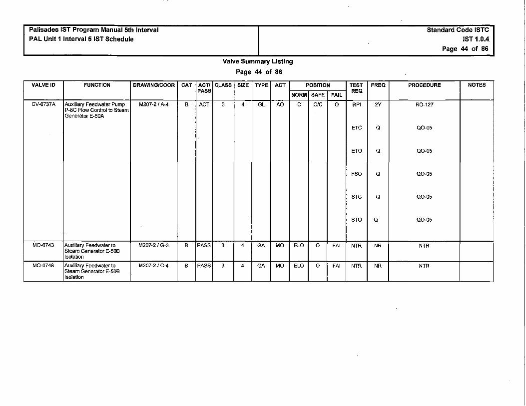
Palisades IST Program Manual 5th Interval PAL Unit 1 Interval 5 IST Schedule
VALVE ID FUNCTION DRAWING/COOR
CV-0737A Auxiliary Feedwater Pump M207-2 / A-4 P-BC Flow Control to Steam Generator E-50A
M0-0743 Auxiliary Feedwater to M207-2 /G-3 Steam Generator E-508 Isolation
M0-0748 Auxiliary Feedwater to M207-2 /C-4 Steam Generator E-508 Isolation
CAT ACT/ PASS
8 ACT
8 PASS
8 PASS
Valve Summary Listing
Page 44 of 86
CLASS SIZE TYPE ACT POSITION
NORM SAFE
3 4 GL AO c O/C
3 4 GA MO ELO 0
3 4 GA MO ELO 0
TEST
FAIL REQ
0 RPI
ETC
ETO
FSO
STC
STO
FAI NTR
FAI NTR
FREQ
2Y
Q
Q
Q
Q
Q
NR
NR
Standard Code ISTC IST 1.0.4
Page 44 of 86
PROCEDURE NOTES
R0-127
Q0-05
Q0-05
Q0-05
Q0-05
Q0-05
NTR
NTR

Palisades IST Program Manual 5th Interval PAL Unit 1 Interval 5 IST Schedule
VALVE ID FUNCTION DRAWING/COOR
CV-0749 Auxiliary Feedwater Flow to M207-2 / E-4 Steam Generator E-50A from P-8A and P-88
M0-0753 Auxiliary Feedwater to M207-2 / E-3 Steam Generator E-50A Isolation
M0-0754 Auxiliary Feedwater to M207-2 / A-4 Steam Generator E-50A Isolation
M0-0755 Auxiliary Feedwater to M207-2 / C-3 Steam Generator E-508 Isolation
M0-0759 Auxiliary Feedwater to M207-2 / A-3 Steam Generator E-50A Isolation
M0-0760 Auxiliary FeedWater to M207-2 / E-3 Steam Generator E-50A Isolation
RV-0783 Auxiliary Feedwater Pumps M207-2 / F-5 P-8A/8 Discharge
M0-0798 Auxiliary Feedwater to M207-2/ G-3 Steam Generator E-508 Isolation
CAT ACT/ PASS
8 ACT
8 PASS
8 PASS
8 PASS
8 PASS
8 PASS
c ACT
8 PASS
Valve Summary Listing
Page 45 of 86
CLASS SIZE TYPE ACT POSITION
NORM SAFE
3 4 GL AO c O/C
3 4 GA MO ELO 0
3 4 GA MO ELO 0
3 4 GA MO ELO 0
3 4 GA MO ELO 0
3 4 GA MO ELO 0
3 2.5 RV SA c O/C
3 4 GA MO ELO 0
TEST
FAIL REQ
0 RPI
ETC
ETO
FSO
STC
STO
FAI NTR
FAI NTR
FAI NTR
FAI NTR
FAI NTR
N/A RV
FAI NTR
FREQ
2Y
Q
Q
Q
Q
Q
NR
NR
NR
NR
NR
10Y
NR
Standard Code ISTC IST 1.0.4
Page 45 of 86
PROCEDURE NOTES
R0-127
Q0-05
Q0-05
Q0-05
Q0-05
Q0-05
NTR
NTR
NTR
NTR
NTR
RT-116
NTR

Palisades IST Program Manual 5th Interval PAL Unit 1 Interval 5 IST Schedule
VALVE ID FUNCTION DRAWING/COOR
MV-FW211 Auxiliary Feedwater Pump M205-2 / C-8 Turbine Cooling Water Outlet 3-Way Valve
MV-FW218 CHEM ADD SUPPLY TO P- M220-2 / A-7 8A/B SUCTION
CK-FW411 Auxiliary Feedwater Line M207-2 I G-6 From P-8B to T-2
CK-FW412 Auxiliary Feedwater Line M207-21 E-6 From P-8A to T-2
CK-FW420 CHEMICAL ADDITION M220-1 I C-6 LINE TO AFW P-8C
CK-FW701 Feedwater Containment M207-1A I G-5 Isolation Valve Loop B
CK-FW702 Feedwater Containment M207-1A I G-6 Isolation Valve Loop A
CAT ACT/ PASS
B ACT
B PASS
c ACT
c ACT
c ACT
c ACT
c ACT
Valve Summary Listing
Page 46 of 86
CLASS SIZE TYPE ACT POSITION
NORM SAFE
3 1.5 3W H N OIC
3 1 GA H c c
3 2 CK SA c 0
3 2 CK SA c 0
3 1 CK SA OIC c
2 18 CK SA 0 c
2 18 CK SA 0 c
TEST FREQ
FAIL REQ
NIA MS 2Y
NIA NTR NR
NIA BOC CM
cvo CM
NIA BOC CM
cvo CM
NIA BOO CM
eve CM
NIA eve cs
cvo cs
NIA eve cs
cvo cs
Standard Code ISTC IST 1.0.4
Page 46 of 86
PROCEDURE NOTES
PMID 50084033-01
NTR
CMJ-AFW-C-01 CMJ-AFW-C-01
CMJ-AFW-C-01 CMJ-AFW-C-01
CMJ-AFW-C-01 CMJ-AFW-C-01
CMJ-AFW-C-01 CMJ-AFW-C-01
CMJ-AFW-C-06 CMJ-AFW-C-06
CMJ-AFW-C-06 CMJ-AFW-C-06
Q0-24 CSJ-37 MFW Supply to SIG E-50B Check Valves
Q0-24 CSJ-37 MFW Supply to SIG E-50B Check Valves
Q0-24 CSJ-37 MFW Supply to SIG E-508 Check Valves
Q0-24 CSJ-37 MFW Supply to SIG E-50B Check Valves
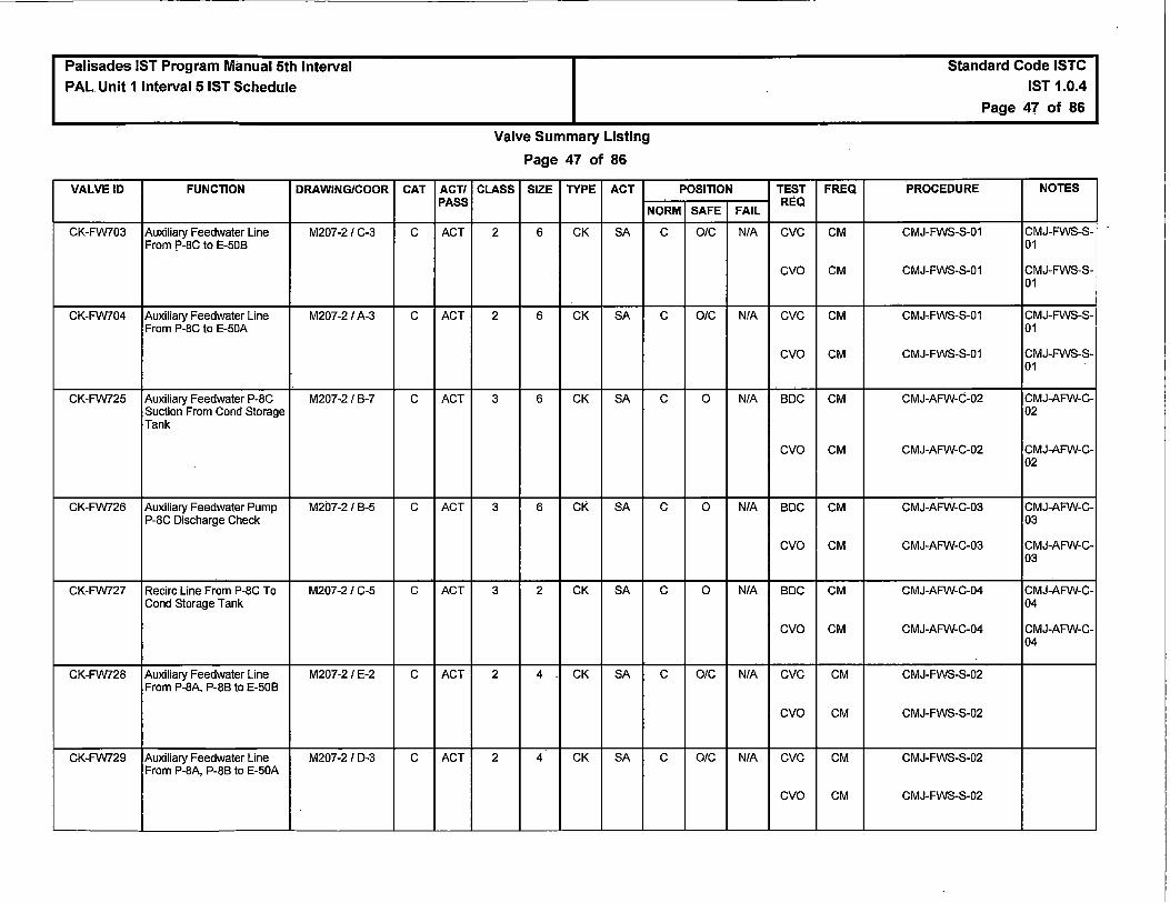
Palisades IST Program Manual 5th Interval
PAL Unit 1 Interval 5 IST Schedule
VALVE ID FUNCTION DRAWING/COOR
CK-FW703 Auxiliary Feedwater Line M207-2 / C-3 From P-8C to E-50B
CK-FW704 Auxiliary Feedwater Line M207-2 / A-3 From P-8C to E-50A
CK-FW725 Auxiliary Feedwater P-8C M207-2 / B-7 Suction From Cond Storage Tank
CK-FW726 Auxiliary Feedwater Pump M207-2 / B-5 P-8C Discharge Check
CK-FW727 Recirc Line From P-8C To M207-2 / C-5 Cond Storage Tank
CK-FW728 Auxiliary Feedwater Line M207-2 / E-2 From P-8A, P-8B to E-50B
CK-FW729 Auxiliary Feedwater Line M207-2 / D-3 From P-8A, P-8B to E-50A
CAT ACT/ PASS
c ACT
c ACT
c ACT
c ACT
c ACT
c ACT
c ACT
Valve Summary Listing
Page 47 of 86
CLASS SIZE TYPE ACT POSITION
NORM SAFE
2 6 CK SA c OIC
2 6 CK SA c O/C
3 6 CK SA c 0
3 6 CK SA c 0
3 2 CK SA c 0
2 4 CK SA c OIC
2 4 CK SA c O/C
TEST FREQ
FAIL REQ
N/A eve CM
cvo CM
N/A eve CM
cvo CM
N/A BOC CM
cvo CM
N/A BOC CM
cvo CM
N/A BOC CM
cvo CM
N/A eve CM
cvo CM
N/A eve CM
cvo CM
Standard Code ISTC IST 1.0.4
Page 47 of 86
PROCEDURE NOTES
CMJ-FWS-S-01 CMJ-FWS-S-01
CMJ-FWS-S-01 CMJ-FWS-S-01
CMJ-FWS-S-01 CMJ-FWS-S-01
CMJ-FWS-S-01 CMJ-FWS-S-01
CMJ-AFW-C-02 CMJ-AFW-C-02
CMJ-AFW-C-02 CMJ-AFW-C-02
CMJ-AFW-C-03 CMJ-AFW-C-03
CMJ-AFW-C-03 CMJ-AFW-C-03
CMJ-AFW-C-04 CMJ-AFW-C-04
CMJ-AFW-C-04 CMJ-AFW-C-04
CMJ-FWS-S-02
CMJ-FWS-S-02
CMJ-FWS-S-02
CMJ-FWS-S-02

Palisades IST Program Manual 5th Interval PAL Unit 1 Interval 5 IST Schedule
VALVE ID FUNCTION DRAWING/COOR
CK-FW741 Auxiliary Feedwater Pump M207-2 I E-6 P-8A Discharge
CK-FW743 Auxiliary Feedwater Pump M207-2 I H-6 P-88 Discharge
MV-FW746 MAIN FW TO SIG E-50A M207-1A I H-7 TEST CONN (MZ-7)
MV-FW747 MAIN FW TO SIG E-508 M207-1A I H-5 TEST CONN (MZ-8)
MV-FW750 Service Water to Auxiliary M207-2 I A-7 Feedwater Pump P-8C Isolation
MV-FW750A Service Water to Auxiliary M207-2 I B-7 Feedwater Pump P-8C Isolation
MV-FW759 Service Water to Auxiliary M207-2 I B-7 Feedwater Pump P-8C Vent
MV-FW774 Auxiliary Feedwater Pumps M207-21 H-7 P-8NB Fire Water Supply Downstream Isolation
MV-ES116 FLEX HPSI CONNECTION M204-1AI H-5 ISO VALVE
MV-ES117 FLEX HPSI CONNECTION M204-1A I H-5 ISO VALVE
MV-ES3007A CK-3104 TEST TAP M203-21G-8
MV-ES3009A CK-3119 TEST TAP M203-2 I E-7
MV-ES3011A CK-3134 TEST TAP M203-2 I D-8
MV-ES3013A CK-3149 TEST TAP M203-2 I B-7
CAT ACT/ PASS
c ACT
c ACT
B PASS
B PASS
B ACT
B ACT
B ACT
B ACT
B PASS
B PASS
B PASS
B PASS
B PASS
B PASS
Valve Summary Listing
Page 48 of 86
CLASS SIZE TYPE ACT POSITION
NORM SAFE
3 6 CK SA c OIC
3 6 CK SA c OIC
2 0.75 GA H LC c
2 0.75 GA H LC c
3 4 GA H LC OIC
3 4 GA H LC OIC
3 1 GL H 0 c
3 4 GA H LC OIC
2 4 GA H LC c
2 4 GA H LC c
2 0.75 GL H LC c
2 0.75 GL H LC c
2 0.75 GL H LC c
2 0.75 GL H LC c
TEST FREQ
FAIL REQ
NIA eve CM
cvo CM
NIA eve CM
cvo CM
NIA NTR NR
NIA NTR NR
NIA MS 2Y
NIA MS 2Y
NIA MS 2Y
NIA MS. 2Y
NIA NTR NR
NIA NTR NR
NIA NTR NR
NIA NTR NR
NIA NTR NR
NIA NTR NR
Standard Code ISTC
IST 1.0.4
Page 48 of 86
PROCEDURE NOTES
CMJ-AFW-C-07 CMJ-AFW-C-07
CMJ-AFW-C-07 CMJ-AFW-C-07
CMJ-AFW-C-07 CMJ-AFW-C-07
CMJ-AFW-C-07 CMJ-AFW-C-07
NTR
NTR
PMID 50083972-01
PMID 50083972-01
PMID 50083972-01
PMID 50083972-01
NTR
NTR
NTR
NTR
NTR
NTR

Palisades IST Program Manual 5th Interval
PAL Unit 1 Interval 5 IST Schedule
VALVE ID FUNCTION DRAWING/COOR
MV-ES3008 CK-3103 TEST TAP ROOT M203-2 / F-8
MV-ES3010 TEST TAP TO CK-ES3118 M203-2 / D-8
MV-ES3012 CK-3133 TEST TAP ROOT M203-2 / C-8
MV-ES3014 CK-3148 TEST TAP ROOT M203-2 / A-8
CV-1398 Nitrogen Supply M222-1 / D-3 Containment Isolation Valve
CAT ACT/ PASS
B PASS
B PASS
B PASS
B PASS
A ACT
Valve Summary Listing
Page 49 of 86
CLASS SIZE TYPE ACT POSITION
NORM SAFE
2 0.75 GL H LC c
2 0.75 GL H LC c
2 0.75 GL H LC c
2 0.75 GL H LC c
2 1 GL AO O/C O/C
TEST
FAIL REQ
N/A NTR
N/A NTR
N/A NTR
N/A NTR
c RPI
LTJ
ETC
ETO
FSC
STC
STO
FREQ
NR
NR
NR
NR
2Y
AppJ
Q
Q
Q
Q
Q
Standard Code ISTC
IST 1.0.4
Page 49 of 86
PROCEDURE NOTES
NTR
NTR
NTR
NTR
Q0-05
R0-032-26
Q0-05
Q0-05
Q0-05
Q0-05
Q0-05

Palisades IST Program Manual 5th Interval PAL Unit 1 Interval 5 IST Schedule
VALVE ID FUNCTION DRAWING/COOR
SV-2412A Containment Hydrogen M224-2 / C-8 Monitoring Suction CfV (Right Channel)
SV-24128 Containment Hydrogen M224-2 / C-7 Monitoring Suction CIV (Right Channel)
CAT ACT/ PASS
A ACT
A ACT
Valve Summary Listing
Page 50 of 86
CLASS SIZE TYPE ACT POSITION
NORM SAFE
2 0.5 GL so c OIC
2 0.5 GL so c O/C
TEST
FAIL REQ
c RPI
LTJ
ETC
ETO
FSC
STC
STO
c RPI
LTJ
ETC
ETO
FSC
STC
STO
FREQ
2Y
AppJ
Q
Q
Q
Q
Q
2Y
AppJ
Q
Q
Q
Q
Q
Standard Code ISTC IST 1.0.4
Page 50 of 86
PROCEDURE NOTES
R0-11
R0-032-408
Q0-05
Q0-05
Q0-05
Q0-05
Q0-05
R0-11
R0-032-408
Q0-05
Q0-05
Q0-05
Q0-05
Q0-05

Palisades IST Program Manual 5th Interval PAL Unit 1 Interval 5 IST Schedule
VALVE ID FUNCTION DRAWING/COOR
SV-2413A Containment Hydrogen M224-2 / F-8 Monitoring Suction CIV (Left Channel)
SV-24138 Containment Hydrogen M224-2/ F-7 Monitoring Suction CIV (Left Channel)
CAT ACT/ PASS
A ACT
A ACT
Valve Summary Listing
Page 51 of 86
CLASS SIZE TYPE ACT POSITION
NORM SAFE
2 0.5 GL so c OIC
2 0.5 GL so c O/C
TEST
FAIL REQ
c RPI
LTJ
ETC
ETO
FSC
STC
STO
c RPI
LTJ
ETC
ETO
FSC
STC
STO
FREQ
2Y
AppJ
Q
Q
Q
Q
Q
2Y
AppJ
Q
Q
Q
Q
Q
Standard Code ISTC IST 1.0.4
Page 51 of 86
PROCEDURE NOTES
R0-11
R0-032-21A
Q0-05
Q0-05
Q0-05
Q0-05
Q0-05
R0-11
R0-032-21A
Q0-05
Q0-05
Q0-05
Q0-05
Q0-05

Palisades IST Program Manual 5th Interval PAL Unit 1 Interval 5 IST Schedule
VALVE ID FUNCTION DRAWING/COOR
SV-2414A Containment Hydrogen M224-2/ D-8 Monitoring Discharge CIV (Right Channel)
SV-24148 Containment Hydrogen M224-2 / D-7 Monitoring Discharge CIV (Right Channel)
CAT ACT/ PASS
A ACT
A ACT
Valve Summary Listing
Page 52 of 86
CLASS SIZE TYPE ACT POSITION
NORM SAFE
2 0.5 GL so c O/C
2 0.5 GL so c OIC
TEST
FAIL REQ
c RPI
LTJ
ETC
ETO
FSC
STC
STO
c RPI
LTJ
ETC
ETO
FSC
STC
STO
FREQ
2Y
AppJ
Q
Q
Q
Q
Q
2Y
AppJ
Q
Q
Q
Q
Q
Standard Code ISTC IST 1.0.4
Page 52 of 86
PROCEDURE NOTES
R0-11
R0-032-40A
Q0-05
Q0-05
Q0-05
Q0-05
Q0-05
R0-11
R0-032-40A
Q0-05
Q0-05
Q0-05
Q0-05
Q0-05

Palisades IST Program Manual 5th Interval
PAL Unit 1 Interval 5 IST Schedule
VALVE ID FUNCTION DRAWING/COOR
SV-2415A Containment Hydrogen M224-2 IG-8 Monitoring Discharge CIV (Left Channel)
SV-24158 Containment Hydrogen M224-2 IG-7 Monitoring Discharge CIV (Left Channel)
MV-N21312 ISOL FOR WEST UPPER M222-31 F-4 PENETRATIONS NORTH
MV-N21313 ISOL FOR EAST UPPER M222-3 I F-4 PENETRATIONS NORTH
CAT ACT/ PASS
A ACT
A ACT
B PASS
B PASS
Valve Summary Listing
Page 53 of 86
CLASS SIZE TYPE ACT POSITION
NORM SAFE
2 0.5 GL so c OIC
2 0.5 GL so c OIC
2 GA H 0 0
2 GA H 0 0
TEST
FAIL REQ
c RPI
LTJ
ETC
ETO
FSC
STC
STO
c RPI
LTJ
ETC
ETO
FSC
STC
STO
NIA NTR
NIA NTR
FREQ
2Y
AppJ
Q
Q
Q
Q
Q
2Y
AppJ
Q
Q
Q
Q
Q
NR
NR
Standard Code ISTC IST 1.0.4
Page 53 of 86
PROCEDURE NOTES
R0-11
R0-032-21
Q0-05
Q0-05
Q0-05
Q0-05
Q0-05
R0-11
R0-032-21
Q0-05
Q0-05
Q0-05
Q0-05
Q0-05
NTR
NTR

Palisades IST Program Manual 5th Interval PAL Unit 1 lnterval 5 IST Schedule
VALVE ID FUNCTION DRAWING/COOR
MV-N2/314 ISOLATION FOR LOWER M222-3 / F-4 PENETRATIONS NORTH
MV-N2/331 N2 STATION 7 UPPER M222-3/G-6 PENETRATIONS ISOL
MV-N2/332 N2 STATION 7 MIDDLE M222-3/G-6 PENETRATIONS ISOL
MV-N2/333 N2 STATION 7 LOWER M222-3/ G-6 PENETRATIONS ISOL
MV-N2/335 N2 STATION 7 Pl-2286 / M222-3 /G-5 EZ-0144 ISOL
MV-N2/337 NITROGEN ISOLATION M222-3 / F-3 FOR EZ-0249
CK-N2/400 Nitrogen Supply M222-1 / D-3 Containment Isolation Valve
CK-N2/462 North Electrical Penetration M222-3 /E-4 N2 Supply Check
CK-N2/465 South Electrical Penetration M222-3/G-7 N2 Supply Check
MV-N2/581 CONTAINMENT M222-1 / D-3 PENETRATION TEST TAP ISOLATION
MV-N2/585 N2 STATION 6 TEST M222-3 / F-4 CONN (NORTH)
CAT ACT/ PASS
B PASS
B PASS
B PASS
B PASS
B PASS
B PASS
A/C ACT
A/C ACT
A/C ACT
B PASS
B PASS
Valve Summary Listing
Page 54 of 86
CLASS SIZE TYPE ACT POSITION
NORM SAFE
2 GA H 0 0
2 GA H 0 0
2 GA H 0 0
2 GA H 0 0
2 GA H 0 0
2 GA H 0 0
2 1 CK SA O/C c
2 0.5 CK SA O/C OIC
2 0.375 CK SA O/C O/C
2 1 GL H LC c
2 GA H LC c
TEST FREQ
FAIL REQ
N/A NTR NR
N/A NTR NR
N/A NTR NR
NIA NTR NR
N/A NTR NR
N/A NTR NR
N/A LTJ AppJ
BOO CM
eve CM
N/A LTJ AppJ
eve CM
cvo CM
N/A LTJ AppJ
eve CM
cvo CM
N/A NTR NR
N/A NTR NR
Standard Code ISTC
IST 1.0.4
Page 54 of 86
PROCEDURE NOTES
NTR
NTR
NTR
NTR
NTR
NTR
R0-032-26
CMJ-CIS-S-04 CMJ-CIS-S-04
CMJ-CIS-S-04 CMJ-CIS-S-04
R0-032-North
CMJ-CIS-C-06 CMJ-CIS-C-06
CMJ-CIS-C-06 CMJ-CIS-C-06
R0-032-South
CMJ-CIS-C-06 CMJ-CIS-C-06
CMJ-CIS-C-06 CMJ-CIS-C-06
NTR
NTR

I
Palisades IST Program Manual 5th Interval PAL Unit 1 Interval 5 IST Schedule
VALVE ID FUNCTION DRAWING/COOR
MV-N2/588 N2 STATION 7 TEST M222-3 / F-6 CONN (SOUTH)
CV-0501 Main Steam Isolation Valve M205-1 / G-8 SG E-508 to HP Turbine
M0-0501 Steam Generator E-508 M205-1 / G-7 MSIV Bypass Valve
CAT ACT/ PASS
B PASS
B/C ACT
B PASS
Valve Summary Listing
Page 55 of 86
CLASS SIZE TYPE ACT POSITION
NORM SAFE
2 GA H LC c
2 30 CK AO 0 c
2 3 GA MO c c
TEST FREQ
FAIL REQ
N/A NTR NR
c RPI 2Y
eve cs
ETC cs
FSC cs
STC cs
FAI RPI 2Y
Standard Code ISTC IST 1.0.4
Page 55 of 86
PROCEDURE NOTES
NTR
Q0-37
Q0-37 CSJ-15 Main Steam Isolation Valves to HP Turbine
Q0-37 CSJ-15 Main Steam Isolation Valves to HP Turbine
Q0-37 CSJ-15 Main Steam Isolation Valves to HP Turbine
Q0-37 CSJ-15 Main Steam Isolation Valves to HP Turbine
Q0-37

Palisades IST Program Manual 5th Interval PAL Unit 1 Interval 5 IST Schedule
VALVE ID FUNCTION DRAWING/COOR
CV-0510 Main Steam Isolation Valve M205-1 / G-7 SG E-50A to HP Turbine
M0-0510 Steam Generator E-50A M205-1 / G-7 MSIV Bypass Valve
CV-05228 Steam Supply From E-50A M205-2 / F-7 To Auxiliary Feed Pump Turbine
CAT ACT/ PASS
B/C ACT
B PASS
B ACT
Valve Summary Listing
Page 56 of 86
CLASS SIZE TYPE ACT POSITION
NORM SAFE
2 30 CK AO 0 c
2 3 GA MO c c
2 4 GL AO c O/C
TEST FREQ
FAIL REQ
c RPI 2Y
eve cs
ETC cs
FSC cs
STC cs
FAI RPI 2Y
c RPI 2Y
ETC Q
ETO Q
FSC Q
STC Q
STO Q
Standard Code ISTC IST 1.0.4
Page 56 of 86
PROCEDURE NOTES
Q0-37
Q0-37 CSJ-15 Main Steam Isolation Valves to HP Turbine
Q0-37 CSJ-15 Main Steam Isolation Valves to HP Turbine
Q0-37 CSJ-15 Main Steam Isolation Valves to HP Turbine
Q0-37 CSJ-15 Main Steam Isolation Valves to HP Turbine
Q0-37
Q0-05
Q0-05
Q0-05
Q0-05
Q0-05
Q0-05

Palisades IST Program Manual 5th Interval PAL Unit 1 Interval 5 IST Schedule
VALVE ID FUNCTION DRAWING/COOR
CV-0738 Steam Generator B M226-1 / C-7 Slowdown Valve
CV-0739 Steam Generator A M226-1 / D-7 Slowdown Valve
CV-0767 Steam Generator E-50A M226-1 / F-8 Bottom Slowdown Valve
CV-0768 Steam Generator E-508 M226-1 / E-8 Bottom Slowdown Valve
CV-0779 Steam Generator E-508 M207-1 / F-4 Atmospheric Dump
CV-0780 Steam Generator E-508 M207-1 / F-4 Atmospheric Dump
CV-0781 Steam Generator E-50A M207-1 / F-5 Atmospheric Dump
CAT ACT/ PASS
B ACT
B ACT
' B ACT
B ACT
,_
B PASS
B PASS
B PASS
Valve Summary Listing
Page 57 of 86
CLASS SIZE TYPE ACT POSITION
NORM SAFE
2 2 ANG AO O/C c
2 2 ANG AO OIC c
2 2 ANG AO OIC c
2 2 ANG AO O/C c
2 8 GL AO c c
2 8 GL AO c c
2 8 GL AO c c
TEST
FAIL REQ
c RPI
ETC
FSC
STC
c RPI
ETC
FSC
STC
c RPI
ETC
FSC
STC
c RPI
ETC
FSC
STC
c RPI
c RPI
c RPI
FREQ
2Y
Q
Q
Q
2Y
Q
Q
Q
2Y
Q
Q
Q
2Y
Q
Q
Q
2Y
2Y
2Y
Standard Code ISTC
IST 1.0.4
Page 57 of 86
PROCEDURE NOTES
Q0-05
Q0-05
Q0-05
Q0-05
Q0-05
Q0-05
Q0-05
Q0-05
Q0-05
Q0-05
Q0-05
Q0-05
Q0-05
Q0-05
Q0-05
Q0-05
Q0-06
Q0-06
Q0-06

Palisades IST Program Manual 5th Interval PAL Unit 1 Interval 5 IST Schedule
VALVE ID FUNCTION DRAWING/COOR
CV-0782 Steam Generator E-50A M207-1 / F-5 Atmospheric Dump
CK-MS402 Steam Supply from E-50A M205-2/ F-7 ,- to Auxiliary Feedwater
Pump P-8B Check Valve
MV-MS500 MAIN STEAM TO CV- M205-21 F-6 0522B BLEED (MZ-2)
MV-MS515 CV-0782 STEAM TRAP ST- M207-1 I F-6 0792 INLET (MZ-2)
MV-MS517 CV-0781 STEAM TRAP ST- M207-1 I F-6 0791 BYPASS (MZ-2)
MV-MS518 E-50A ASDV CV-0781 M207-1 / F-6 INLET DRAIN (MZ-2)
MV-MS519 CV-0781 STEAM TRAP ST- M207-1 I F-6 0791 INLET (MZ-2)
MV-MS521 CV-0782 STEAM TRAP ST- M207-1 /F-6 0792 BYPASS (MZ-2)
MV-MS522 E-50A ASDV CV-0782 M207-1 I E-6 INLET DRAIN (MZ-2)
MV-MS523 CV-0779 STEAM TRAP ST- M207-1 I F-4 0789 INLET (MZ-3)
MV-MS525 CV-0779 STEAM TRAP ST- M207-1 I F-4 0789 BYPASS (MZ-3)
MV-MS526 E-50B ASDV CV-0779 M207-1 I E-4 INLET DRAIN (MZ-3)
MV-MS527 CVc0780 STEAM TRAP ST- M207-1 / F-4 0790 INLET (MZ-3)
MV-MS529 CV-0780 STEAM TRAP ST- M207-1 I F-4 0790 BYPASS (MZ-3)
MV-MS530 E-50B ASDV CV-0780 M207-1 I F-3 INLET DRAiN (MZ-3)
CV-0101 Flange Leak Drain M201-1 I G-5
CAT ACT/ PASS
B PASS
c ACT
B PASS
B PASS
B PASS
B PASS
B PASS
B PASS
B PASS
B PASS
B PASS
B PASS
B PASS
B PASS
B PASS
B PASS
Valve Summary Listing
Page 58 of 86
CLASS SIZE TYPE ACT POSITION
NORM SAFE
2 8 GL AO c c
3 4 CK SA c 0
2 0.75 GL H LC c
2 0.75 GA H 0 0 . 2 0.75 GL H LC c
2 0.75 GA H LC c
2 0.75 GA H 0 0
2 0.75 GL H LC c
2 0.75 GA H LC c
2 0.75 GA H 0 0
2 0.75 GL H LC c
2 0.75 GA H LC c
2 0.75 GA H 0 0
2 0.75 GL H LC c
2 0.75 GA H LC c
2 0.5 GL AO c c
TEST
FAIL REQ
c RPI
NIA BDC
cvo
NIA NTR
NIA NTR
NIA NTR
NIA NTR
NIA NTR
NIA NTR
NIA NTR
NIA NTR
NIA NTR
NIA NTR
NIA NTR
NIA NTR
NIA NTR
c RPI
FREQ
2Y
CM
CM
NR
NR
NR
NR
NR
NR
NR
NR
NR
NR
NR
NR
NR
2Y
Standard Code ISTC IST 1.0.4
Page 58 of 86
PROCEDURE NOTES
Q0-06
CMJ-MSS-S-01 CMJ-MSS-S-01
CMJ-MSS-S-01 CMJ-MSS-S-01
NTR
NTR
NTR
NTR
NTR
NTR
NTR
NTR
NTR
NTR
NTR
NTR
NTR
Q0-05

Palisades IST Program Manual 5th Interval PAL Unit 1 Interval 5 IST Schedule
VALVE ID FUNCTION DRAWING/COOR
CV-0155 Quench Tank T-73 Makeup M201-2 / G-7 Water Isolation Valve
M0-1042A Power Relief Valve Isolation M201-2 / D-6 Valve
PRV-10428 Power Operated Relief M201-2 / E-6 Valve
CAT ACT/ PASS
A ACT
B ACT
B ACT
Valve Summary Listing
Page 59 of 86
CLASS SIZE TYPE ACT POSITION
NORM SAFE
2 2 GL AO OIC c
1 4 GA MO c OJC
1 4 PORV so c OIC
TEST FREQ
FAIL REQ
c RPI 2Y
LTJ AppJ
ETC Q
FSC Q
STC Q
FAI RPI 2Y
ETC cs
ETO cs
STC cs
STO cs
c ETC 18M
ETO 18M
FSC 18M
STO 18M
RPI 2Y
Standard Code ISTC IST 1.0.4
Page 59 of 86
PROCEDURE NOTES
Q0-05
R0-032-42
Q0-05
Q0-05
Q0-05
Q0-06
Q0-06 CSJ-24 PORVBlock Valves
Q0-06 CSJ-24 PORV Block Valves
Q0-06 CSJ-24 PORVBlock Valves
Q0-06 CSJ-24 PORVBlock Valves
Rl-115
Rl-115
Rl-115
Rl-115
Rl-115

Palisades IST Program Manual 5th Interval PAL Unit 1 Interval 5 IST Schedule
VALVE ID FUNCTION DRAWING/COOR
M0-1043A Power Relief Valve Isolation M201-2 / D-7 Valve
PRV-1043B Power Operated Relief M201-2 / E-7 Valve
CAT ACT/ PASS
B ACT
B ACT
Valve Summary Listing
Page 60 of 86
CLASS SIZE TYPE ACT POSITION
NORM SAFE
1 4 GA MO c O/C
1 4 PORV so c O/C
'
TEST FREQ
FAIL REQ
FAI RPI 2Y
ETC cs
ETO cs
STC cs
STO cs
c ETC 18M
ETO 18M
FSC 18M
STO 18M
RPI 2Y
Standard Code ISTC
IST 1.0.4
Page 60 of 86
PROCEDURE NOTES
Q0-06
Q0-06 CSJ-24 PORV Block Valves
Q0-06 CSJ-24 PORV Block Valves
Q0-06 CSJ-24 PORVBlock Valves
Q0-06 CSJ-24 PORV Block Valves
Rl-115
Rl-115
Rl-115
Rl-115
Rl-115
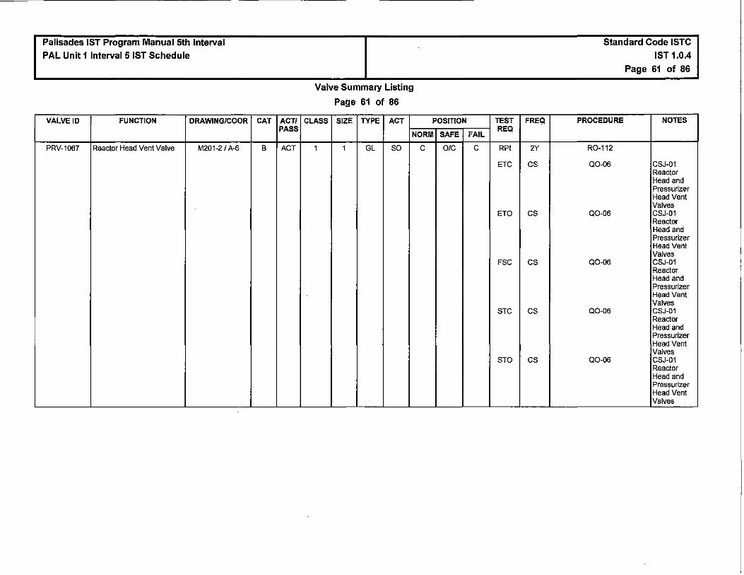
Palisades IST Program Manual 5th Interval
PAL Unit 1 Interval 5 IST Schedule
VALVE ID FUNCTION DRAWING/COOR
PRV-1067 Reactor Head Vent Valve M201-2 / A-6
CAT ACT/ PASS
B ACT
Valve Summary Listing
Page 61 of 86
CLASS SIZE TYPE ACT POSITION
NORM SAFE
1 1 GL so c O/C
TEST FREQ
FAIL REQ
c RPI 2Y
ETC cs
ETO cs
FSC cs
STC cs
STO cs
Standard Code ISTC
IST 1.0.4
Page 61 of 86
PROCEDURE NOTES
R0-112
Q0-06 CSJ-01 Reactor Head and Pressurizer Head Vent Valves
Q0-06 CSJ-01 Reactor Head and Pressurizer Head Vent Valves
Q0-06 CSJ-01 Reactor Head and Pressurizer Head Vent Valves
Q0-06 CSJ-01 Reactor Head and Pressurizer Head Vent Valves
Q0-06 CSJ-01 Reactor Head and Pressurizer Head Vent Valves

Palisades IST Program Manual 5th Interval
PAL Unit 1 Interval 5 IST Schedule
VALVE ID FUNCTION DRAWING/COOR
PRV-1068 Reactor Head Vent Valve M201-2 / A-6
CAT ACT/ PASS
8 ACT
Valve Summary Listing
Page 62 of 86
CLASS SIZE TYPE ACT POSITION
NORM SAFE
1 1 GL so c O/C
TEST FREQ
FAIL REQ
c RPI 2Y
ETC cs
ETO cs
FSC cs
STC cs
STO . cs
Standard Code ISTC IST 1.0.4
Page 62 of 86
PROCEDURE NOTES
R0-112
Q0-06 CSJ-01 Reactor Head and Pressurizer Head Vent Valves
Q0-06 CSJ-01 Reactor Head and Pressurizer Head Vent Valves
Q0-06 CSJ-01 Reactor Head and Pressurizer Head Vent Valves
Q0-06 CSJ-01 Reactor Head and Pressurizer Head Vent Valves
Q0-06 CSJ-01 Reactor Head and Pressurizer Head Vent Valves
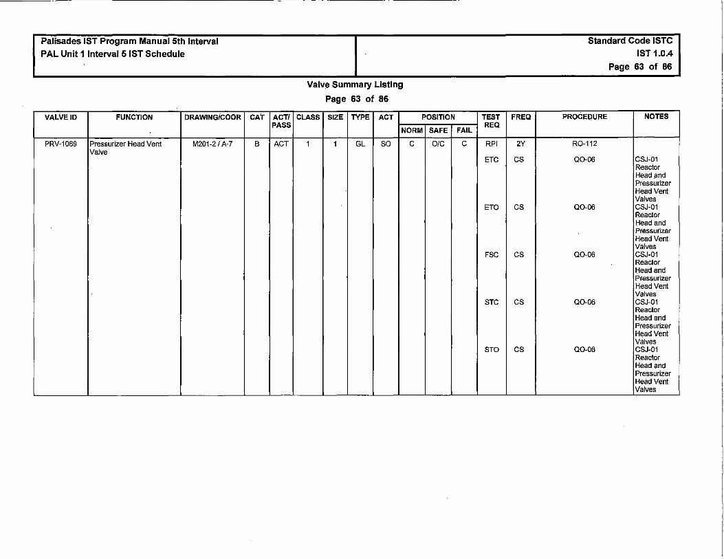
Palisades IST Program Manual 5th Interval PAL Unit 1 Interval 5 IST Schedule
VALVE ID FUNCTION DRAWING/COOR
\
PRV-1069 Pressurizer Head Vent M201-2 / A-7 Valve
CAT ACT/ PASS
B ACT
Valve Summary Listing
Page 63 of 86
CLASS SIZE TYPE ACT POSITION
NORM SAFE
1 1 GL so c OIC
TEST FREQ
FAIL REQ
c RPI 2Y
ETC cs
ETO cs
FSC cs
STC cs
STO cs
Standard Code ISTC IST 1.0.4
Page 63 of 86
PROCEDURE NOTES
R0-112
Q0-06 CSJ-01 Reactor Head and Pressurizer Head Vent Valves
Q0-06 CSJ-01 Reactor Head and Pressurizer Head Vent Valves
Q0-06 CSJ-01 Reactor Head and Pressurizer Head Vent Valves
Q0-06 CSJ-01 Reactor Head and Pressurizer Head Vent Valves
Q0-06 CSJ-01 Reactor Head and Pressurizer Head Vent Valves
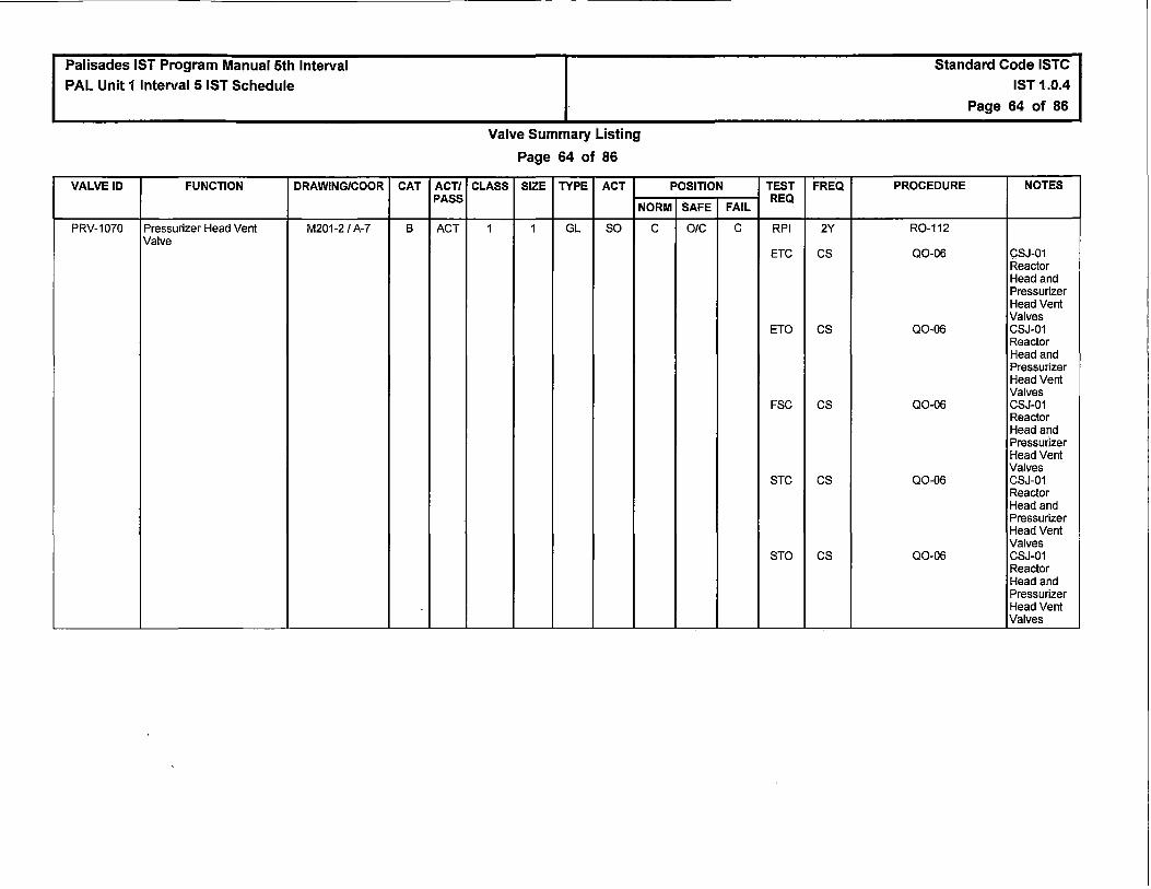
Palisades IST Program Manual 5th Interval PAL Unit 1 Interval 5 IST Schedule
VALVE ID FUNCTION DRAWING/COOR
PRV-1070 Pressurizer Head Vent M201-2 / A-7 Valve
CAT ACT/ PASS
B ACT
Valve Summary Listing
Page 64 of 86
CLASS SIZE TYPE ACT POSITION
NORM SAFE
1 1 GL so c O/C
TEST FREQ
FAIL REQ
c RPI 2Y
ETC cs
ETO cs
FSC cs
STC cs
STO cs
Standard Code ISTC IST 1.0.4
Page 64 of 86
PROCEDURE NOTES
R0-112
Q0-06 CSJ-01 Reactor Head and Pressurizer Head Vent Valves
Q0-06 CSJ-01 Reactor Head and Pressurizer Head Vent Valves
Q0-06 CSJ-01 Reactor Head and Pressurizer Head Vent Valves
Q0-06 CSJ-01 Reactor Head and Pressurizer Head Vent Valves
Q0-06 CSJ-01 Reactor Head and Pressurizer Head Vent Valves

Palisades IST Program Manual 5th Interval PAL Unit 1 Interval 5 IST Schedule
VALVE ID FUNCTION DRAWING/COOR
PRV-1071 Reactor Head and M201-2 / B-8 Pressurizer Head Combined Vent Valve
CAT ACT/ PASS
B ACT
Valve Summary Listing
Page 65 of 86
CLASS SIZE TYPE ACT POSITION
NORM SAFE
1 1 GL so c OIC
TEST FREQ
FAIL REQ
c RPI 2Y
ETC cs
ETO cs
FSC cs
STC cs
STO cs
Standard Code ISTC IST 1.0.4
Page 65 of 86
PROCEDURE NOTES
R0-112
Q0-06 CSJ-01 Reactor Head and Pressurizer Head Vent Valves
Q0-06 CSJ-01 Reactor Head and Pressurizer Head Vent Valves
Q0-06 CSJ-01 Reactor Head and Pressurizer Head Vent Valves
Q0-06 CSJ-01 Reactor Head and Pressurizer Head Vent Valves
Q0-06 CSJ-01 Reactor Head and Pressurizer Head Vent Valves

Palisades IST Program Manual 5th Interval PAL Unit 1 Interval 5 IST Schedule
VALVE ID FUNCTION DRAWING/COOR
PRV-1072 Reactor Head and M201-2 / 8-7 Pressurizer Head Combined Vent Valve
CV-1910 Primary System Sampling M219-1B/C-8 Isolation Valve
CAT ACT/ PASS
B ACT
A ACT
Valve Summary Listing
Page 66 of 86
CLASS SIZE TYPE ACT POSITION
NORM SAFE
1 1 GL so c O/C
1 0.5 GL AO 0 c
TEST FREQ
FAIL REQ __
c RPI 2Y
ETC cs
ETO cs
FSC cs
STC cs
STO cs
c RPI 2Y
LTJ AppJ
ETC Q
FSC Q
STC Q
Standard Code ISTC IST 1.0.4
Page 66 of 86
PROCEDURE NOTES
R0-112
Q0-06 CSJ-01 Reactor Head and Pressurizer Head Vent Valves
Q0-06 CSJ-01 Reactor Head and Pressurizer Head Vent Valves
Q0-06 CSJ-01 Reactor Head and Pressurizer Head Vent Valves
Q0-06 CSJ-01 Reactor Head and Pressurizer Head Vent Valves
Q0-06 CSJ-01 Reactor Head and Pressurizer Head Vent Valves
Q0-05
R0-032-40
Q0-05
Q0-05
Q0-05

Palisades IST Program Manual 5th Interval PAL Unit 1 Interval 5 IST Schedule
VALVE ID FUNCTION DRAWING/COOR
CV-1911 Primary System Sampling M219-1B/B-8 Isolation Valve
MV-PC1033A Loop Drain Isolation Valve M201-1 / F-8
MV-PC1033B Loop Drain Isolation Valve M201-1 / F-8
MV-PC1060A RX N-50 HEAD VENT M201-1 FF-4
MV-PC1060B RX N-50 HEAD VENT M201-1 / G-4
MV-PC1060C RX N-50 HEAD VENT M201-1 / H-4
MV-PC1060D RX N-50 HEAD VENT M201-1 / H-4
MV-PC1094A PCS LOOP 1 HOT LEG M201-1 / C-3 DRAIN I HOT LEG INJ
MV-PC1094B Loop Drain Isolation Valve M201-1 I B,C-3,4
MV-PC1094C Loop Drain Isolation Valve M201-1 / B,C-3,4
MV-PC1126 QUENCH TANK M201-2 / G-7 ISOLATION VALVE TEST
MV-PC1170A PEN MZ-40 PRIMARY M219-1B I B-8 COOLANT SYS SAMPLE TEST
CK-PC1558 Quench Tank T-73 Makeup M201-2 / G-7 Water Isolation Valve
CAT ACT/ PASS
A ACT
B PASS
B PASS
B PASS
B PASS
B PASS
B PASS
B PASS
B PASS
B PASS
B PASS
B PASS
NC ACT
Valve Summary Listing
Page 67 of 86
CLASS SIZE TYPE ACT POSITION
NORM SAFE
2 0.5 GL AO 0 c
1 2 GL H c c
1 2 GL H c c
1 3/4 GA H LO 0
1 3/4 GA H c c
1 GA H c c
1 GA H c c
1 GA H LO 0
1 2 GL H LC c
1 2 GL H LC c
2 1 GL H LC c
2 0.5 NOL H LC c
2 2 CK SA c c
TEST FREQ
FAIL REQ
c RPI 2Y
LTJ AppJ
ETC Q
FSC Q
STC Q
NIA NTR NR
N/A NTR NR
N/A NTR NR
N/A NTR NR
N/A NTR NR
N/A NTR NR
N/A NTR NR
'
N/A NTR NR
N/A NTR NR
N/A NTR NR
N/A NTR NR
N/A LTJ AppJ
BOO CM
eve CM
Standard Code ISTC
IST 1.0.4
Page 67 of 86
PROCEDURE NOTES
Q0-05
R0-032-40
Q0-05
Q0-05
Q0-05
NTR
NTR
NTR
NTR
NTR
NTR
NTR
NTR
NTR
NTR
NTR
R0-032-42
CMJ-CIS-S-02 CMJ-CIS-S-02
CMJ-CIS-S-02 CMJ-CIS-S-02

Palisades IST Program Manual 5th Interval PAL Unit 1 Interval 5 IST Schedule
VALVE ID FUNCTION DRAWING/COOR
CK-PC437 Quench Tank Sample M219-1B I E/F-7 Isolation Check Valve
MV-PC514 PZR T-72 VENT M201-2 / D-6
MV-PC515 PZR T-72 VENT M201-2 / D-6
MV-PC516 PZR T-72 TEST TAP M201-2 /D-7
MV-PC517 PZR T-72 TEST TAP M201-2 / D-7
CV-1001 Primary System Drain Tank M210-2 / E-5, 6 Recirculation Valve
CV-1002 Primary System Drain Tank M210-2 / C-7 Outlet Isolation Valve
CAT ACT/ PASS
c ACT
B PASS
B PASS
B PASS
B PASS
A ACT
A ACT
Valve Summary Listing
Page 68 of 86
CLASS SIZE TYPE ACT POSITION
NORM SAFE
1 0.5 CK SA O/C c
1 2 GL H c c
1 2 GL H c c
1 2 GL H c c
1 2 GL H c c
2 1.5 GL AO O/C c
2 4 GL AO O/C c
TEST
FAIL REQ
N/A eve
BDO
N/A NTR
NIA NTR
N/A NTR
N/A NTR
c RPI
LTJ
ETC
FSC
STC
c RPI
LTJ
ETC
FSC
STC
FREQ
CM
Q
NR
NR
NR
NR
2Y
AppJ
Q
Q
Q
2Y
AppJ
Q
Q
Q
Standard Code ISTC IST 1.0.4
Page 68 of 86
PROCEDURE NOTES
CMJ-PCS-C-01
CMJ-PCS-C-01
NTR
NTR
NTR
NTR
Q0-05
R0-032-37
Q0-05
Q0-05
Q0-05
Q0-05
R0-032-47
Q0-05
Q0-05
Q0-05

Palisades IST Program Manual 5th Interval
PAL Unit 1 Interval 5 IST Schedule
VALVE ID FUNCTION DRAWING/COOR
CV-1004 Degasifier Pump Discharge M210-1A I H-8 Valve
CV-1007 Primary System Drain Tank M210-2 / B-7 Outlet Isolation Valve
CV-1036 Pump P-70 Inlet Valve M210-1A I B-6
CV-1037 Clean Waste Tank M210-1A I B-4 Recirculation
CAT
A
A
A
A
ACT/ PASS
ACT
ACT
ACT
ACT
Valve Summary Listing
Page 69 of 86
CLASS SIZE TYPE ACT POSITION
NORM SAFE
2 3 GL AO O/C c
2 4 GL AO O/C c
2 6 GL AO 0 c
2 3 GL AO 0 c
TEST FREQ
FAIL REQ
c RPI 2Y
LTJ AppJ
ETC Q
FSC Q
STC Q
c RPI 2Y
LTJ AppJ
ETC Q
FSC Q
STC Q
c RPI 2Y
LTJ AppJ
ETC Q
FSC Q
STC Q
c RPI 2Y ,
LTJ AppJ
ETC Q
FSC Q
STC Q
Standard Code ISTC IST 1.0.4
Page 69 of 86
PROCEDURE NOTES
Q0-05
R0-032-41
Q0-05
00"05
Q0-05
Q0-05
R0-032-47
Q0-05
Q0-05
Q0-05
Q0-05
R0-032-49
Q0-05
Q0-05
Q0-05
Q0-05
R0-032-67
Q0-05
Q0-05
Q0-05
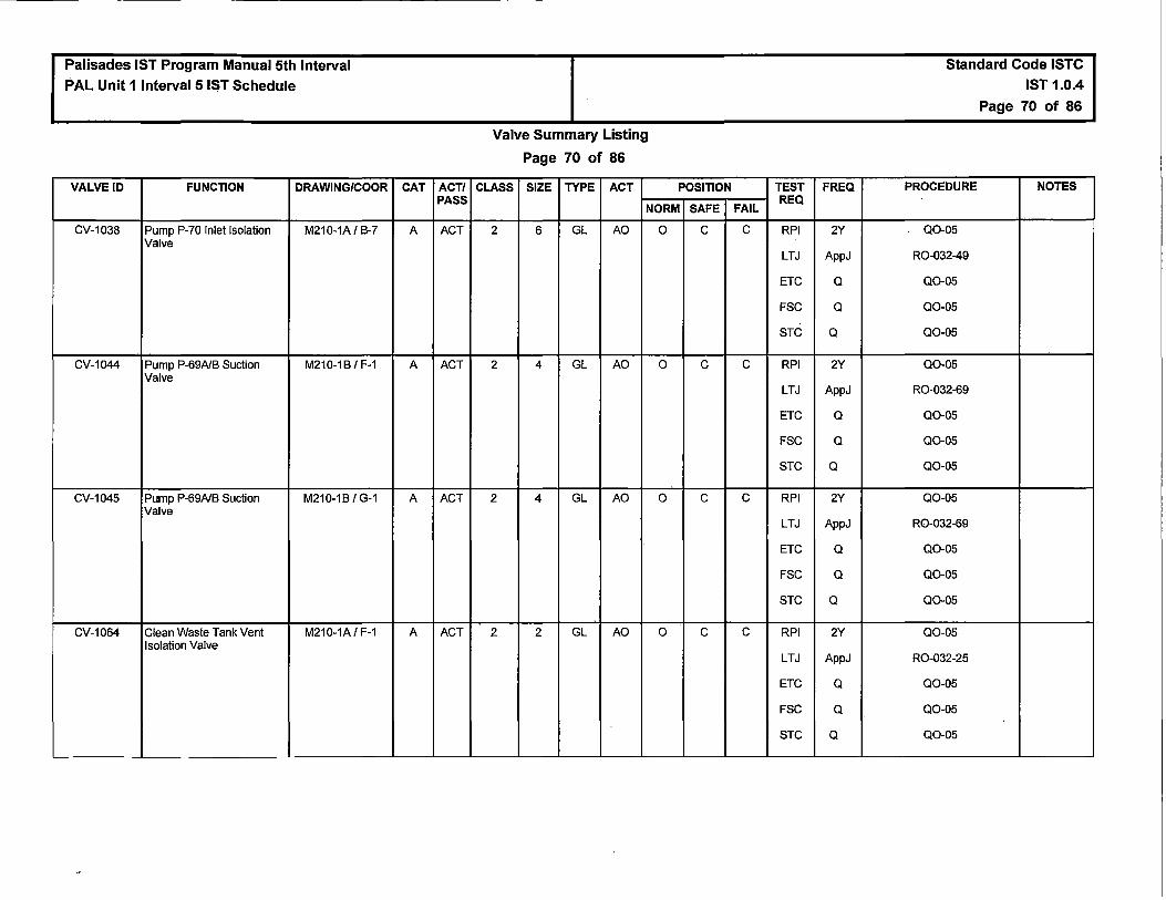
Palisades IST Program Manual 5th Interval
PAL Unit 1 Interval 5 IST Schedule
VALVE ID FUNCTION DRAWING/COOR
CV-1038 Pump P-70 Inlet Isolation M210-1A I B-7 Valve
CV-1044 Pump P-69A/B Suction M210-1 BI F-1 Valve
CV-1045 Pump P-69A/B Suction M210-1B/G-1 Valve
CV-1064 Clean Waste Tank Vent M210-1A I F-1 Isolation Valve
CAT ACT/ PASS
A ACT
A ACT
A ACT
A ACT
Valve Summary Listing
Page 70 of 86
CLASS SIZE TYPE ACT POSITION
NORM SAFE
2 6 GL AO 0 c
2 4 GL AO 0 c
2 4 GL AO 0 c
2 2 GL AO 0 c
TEST
FAIL REQ
c RPI
LTJ
ETC
FSC
STC
c RPI
LTJ
ETC
FSC
STC
c RPI
LTJ
ETC
FSC
STC
c RPI
LTJ
ETC
FSC
STC
FREQ
2Y
AppJ
Q
Q
Q
2Y
AppJ
Q
Q
Q
2Y
AppJ
Q
Q
Q
2Y
AppJ
Q
Q
Q
Standard Code ISTC
IST 1.0.4
Page 70 of 86
PROCEDURE NOTES
Q0-05
R0-032-49
Q0-05
Q0-05
Q0-05
Q0-05
R0-032-69
Q0-05
Q0-05
Q0-05
Q0-05
R0-032-69
Q0-05
Q0-05
Q0-05
Q0-05
R0-032-25
Q0-05
Q0-05
Q0-05

Palisades IST Program Manual 5th Interval PAL Unit 1 Interval 5 IST Schedule
VALVE ID FUNCTION DRAWING/COOR
CV-1065 Clean Waste Tank Vent M210-1A I F-1 Isolation Valve
CV-1103 Containment Sump Drain M211-1 I F-7 Isolation
CV-1104 Containment Sump Drain M211-1 I F-7 Isolation
rviV-CRW175 RADWASTE M210-1C I G-7 DEMINERALIZERS TO SIRWTT-58
CK-CRW403 Primary System Drain Tank M210-2 I E-5 Recirculation Valve
CAT ACT/ PASS
A ACT
A ACT
A ACT
B PASS
NC ACT
Valve Summary Listing
Page 71 of 86
CLASS SIZE TYPE ACT POSITION
NORM SAFE
2 2 GL AO 0 c
2 4 BA AO OIC c
2 4 BA AO OIC c
2 3 GA H c c
2 1.5 CK SA 0 ; c
TEST
FAIL REQ
c RPI
LTJ
ETC
FSC
STC
c RPI
LTJ
ETC
FSC
STC
c RPI
LTJ
ETC
FSC
STC
NIA NTR
NIA LTJ
BOO
eve
FREQ
2Y
AppJ
Q
Q
Q
2Y
AppJ
Q
Q
Q
2Y
AppJ
Q
Q
Q
NR
AppJ
CM
CM
Standard Code ISTC IST 1.0.4
Page 71 of 86
PROCEDURE NOTES
Q0-05
R0-032-25
Q0-05
Q0-05
Q0-05
Q0-05
R0-032-52
Q0-05
Q0-05
Q0-05
Q0-05
R0-032-52
Q0-05
Q0-05
Q0-05
NTR
R0-032-37
CMJ-CIS-S-03 CMJ-CIS-S-03
CMJ-CIS-S-03 CMJ-CIS-S-03

Palisades IST Program Manual 5th Interval PAL Unit 1 Interval 5 IST Schedule
VALVE ID FUNCTION DRAWING/COOR
CK-CRW407 Degasifier Pump Discharge M210-1AIH-8 Check Valve .
CK-CRW408 Clean Waste Receiver M210-1A I B-5 Tanks Recirculation Valve
MV-CRW502 PRI SYS DRN TK T-74 M210-2 I C-7 DISCH PENET MZ-47 TEST
MV-CRW503 PRI SYS DRAIN TK PPS P- M210-2 I E-5 71A/B RECIRC TEST
MV-CRW506 VACUUM DEGASIFIER M210-1A/ H-8 TANK T-57 ISOLATION TEST
MV-CRW512 CWRT VENT HEADER M210-1A I F-1 !SOL (MZ-25) TEST TAP
MV-CRW513 CLEAN WASTE RECIRC M210-1AIB-7 PP INLET ISOLATION TEST
MV-CRW515 CLEAN WASTE RECIRC M210-1A I B-5 PUMP OUTLET ISOL TEST
MV-CRW518 CLEAN TANK ISOLATION M210-1 BI G-2 VALVE TEST
MV-DRW500 Containment Sump Drain M211-1 I F-7 Test Conn (MZ-52)
MV-DRW618 Sensing Line to L T-0382 M232-2A I C-1 Isolation Valve
MV-DRW618A Sensing Line To L T-0382 M232-2A I B-2 Isolation Valve
CAT ACT/ PASS
A/C ACT
A/C ACT
B PASS
B PASS
B PASS
B PASS
- B PASS
B PASS
B PASS
B PASS
B PASS
B PASS
Valve Summary Listing
Page 72 of 86
CLASS SIZE TYPE ACT POSITION
NORM SAFE
2 3 CK SA OIG c
2 3 CK SA OIG c
2 1 GL H LC c
2 1 GL H LC c
2 GL H LC c
2 1 GL H LC c
2 1 GL H LC c
..
2 GL H LC c
2 1 GL H LC c
2 1 GL H LC c
2 1 GL H LO 0
2 0.375 GL H LO 0
TEST FREQ
FAIL REQ
NIA LTJ AppJ
BDO CM
eve CM
NIA LTJ AppJ
BDO CM
eve CM
NIA NTR NR
NIA NTR NR
NIA NTR NR
NIA NTR NR
NIA NTR NR
NIA NTR NR
NIA NTR NR
NIA NTR NR -
NIA NTR NR
NIA NTR NR
Standard Code ISTC IST 1.0.4
Page 72 of 86
PROCEDURE NOTES
R0-032-41
CMJ-CIS-S-01 CMJ-CIS-S-01
CMJ-CIS-S-01 CMJ-CIS-S-01
R0-032-67
CMJ-CIS-S-01 CMJ-CIS-S-01
CMJ-CIS-S-01 CMJ-CIS-S-01
NTR
NTR
NTR
NTR
NTR
NTR
NTR
NTR
R0-032-52A
NTR

Palisades IST Program Manual 5th Interval PAL Unit 1 Interval 5 IST Schedule
VALVE ID FUNCTION DRAWING/COOR
MV-DRW6188 L T-0382 Equalizing Valve M232-2A I 8-1
MV-DRW618C Test Connection To LT- M232-2A I 8-1 0382
MV-DRW618D Test Connection To LT- M232-2A I 8-1 0382
MV-DRW618E Seal Pot To L T-0382 M232-2A I C-1
MV-DRW618F Seal Pot To L T-0382 M232-2A I C-1
MV-DRW618G Seal Pot To L T-0382 M232-2AI C-1
MV-DRW618H Seal Pot To L T-0382 M232-2AI C-1
MV-DRW619 L T-0383 Sensing Line M232-2A I C-2
MV-DRW619A Sensing Line To L T-0383 M232-2A I 8-2
MV-DRW6198 L T-0383 Equalizing Valve M232-2A I 8-2
MV-DRW619C Test Connection To LT- M232-2A I 8-2 0383
MV-DRW619D Test Connection To LT- M232-2A I 8-2 0383
MV-DRW619E Seal Pot To L T-0383 M232-2A I C-2
MV-DRW619F Seal Pot To L T-0383 M232-2A I C-2
MV-DRW619G Seal Pot To L T-0383 M232-2A I C-2
MV-DRW619H Seal Pot To LT-0383 M232-2A I C-3
MV-VA1814E Sensing Line To L T-0382 M232-2A I 8-2 Isolation Valve
MV-VA606A Sensing Line To L T-0383 M232-2A I 8-2
CAT ACT/ PASS
8 PASS
A PASS
A PASS
A PASS
A PASS
A PASS
A PASS
8 PASS
8 PASS
8 PASS
A PASS
A PASS
A PASS
A PASS
A PASS
A PASS
8 PASS
8 PASS
Valve Summary Listing
Page 73 of 86
CLASS SIZE TYPE ACT POSITION
NORM SAFE
2 0.375 GL H LC c
2 0.375 GL H LC c
2 0.375 GL H LC c
2 0.375 GL H LC c
2 0.375 GL H LC c
2 0.375 GL H LC c
2 0.375 GL H LC c
2 1 GL H LO 0
2 0.375 GL H 0 0
2 0.375 GL H LC c
2 0.375 GL H LC c
2 0.375 GL H LC c
2 0.375 GL H LC c
2 0.375 GL H LC c
2 0.375 GL H LC c
2 0.375 GL H LC c
2 0.375 GL H LO 0
2 0.375 GL H LO 0
TEST
FAIL REQ
N/A NTR
NIA LTJ
NIA LTJ
NIA LTJ
N/A LTJ
NIA LTJ
NIA LTJ
NIA NTR
NIA NTR
NIA NTR
N/A LTJ
N/A LTJ
NIA LTJ
N/A LTJ
NIA LTJ
N/A LTJ
NIA NTR
N/A NTR
FREQ
NR
AppJ
AppJ
AppJ
AppJ
AppJ
AppJ
NR
NR
NR
AppJ
AppJ
AppJ
AppJ
AppJ
AppJ
NR
NR
Standard Code ISTC
IST 1.0.4
Page 73 of 86
PROCEDURE NOTES
NTR
R0-032-52A
R0-032-52A
R0-032-52A
R0-032-52A
R0-032-52A
R0-032-52A
R0-032-528
NTR
NTR
R0-032-528
R0-032-528
R0-032-528
R0-032-528
R0-032-528
R0-032-528
R0-032-52A
R0-032-528

Palisades IST Program Manual 5th Interval PAL Unit 1 Interval 5 IST Schedule
VALVE ID FUNCTION DRAWING/COOR
CV-0939 MZ-11 Shield Cooling M221-1 / D-2 Surge TK T-62 Inlet Isolation
MV-ES3163 SHUTDOWN COOLING M204-1 / E-1 CROSSOVER FROM LP INJECT
MV-ES3205 TEMPORARY M204-1 / C-2 CONNECTION FOR SFP COOLING
MV-ES3214 SHUTDOWN COOLING TO M204-1 / E-7 SPENT FUEL POOL
-MV-SFP105 RECIRC BSTR PP P-82 M221-2 / 8-4 SUCT FROM SFP SKIMMERS
MV-SFP109 SFP FILTER F-50 INLET M221-2 / F-4
MV-SFP110 SFP FILTER F-50 OUTLET M221-2 / E-4
MV-SFP117 MZ-72 Reactor Cavity M221-2 / C-2 Drain & Recirc Inlet
MV-SFP118 MZ-72 Reactor Cavity M221-2 / C-4 Drain & Recirc Outlet
MV-SFP119 Spent Fuel Pool Supply to M221-2 / E-6 Reactor Cavity Isolation Valve
MV-SFP120 MZ-64 Reactor Cavity Fill & M221-2 / D-2 Recirc Inlet
CAT ACT/ PASS
A ACT
B PASS
B PASS
B PASS
B PASS
B PASS
B PASS
A PASS
A PASS
B PASS
A PASS
Valve Summary Listing
Page 74 of 86
CLASS SIZE TYPE ACT POSITION
NORM SAFE
2 1.5 GL AO 0 c
2 1 GL H LC c
2 8 GA H LC c
2 8 GL H LC c
3 4 GA H c c
3 3 GA H c c
3 3 GL H c c
2 8 GA H LC c
2 8 GA H LC c
3 6 GL H LC c
2 6 GA H LC c
TEST
FAIL REQ
c RPI
LTJ
ETC
FSC
STC
N/A NTR
N/A NTR
N/A NTR
N/A NTR
N/A NTR
N/A NTR
N/A LTJ
N/A LTJ
NIA NTR
N/A LTJ
FREQ
2Y
AppJ
Q
Q
Q
NR
NR
NR
NR
NR
NR
AppJ
AppJ
NR
AppJ
Standard Code ISTC IST 1.0.4
Page 74 of 86
PROCEDURE NOTES
Q0-05
R0-032-11
Q0-05
Q0-05
Q0-05
NTR
NTR
NTR
NTR
NTR
NTR
R0-032-72
R0-032-72
NTR
R0-032-64

Palisades IST Program Manual 5th Interval
PAL Unit 1 Interval 5 IST Schedule
VALVE ID FUNCTION DRAWING/COOR
MV-SFP121 MZ-64 Reactor Cavity Fill & M221-2 / D-2 Recirc Outet
MV-SFP122 SFP DEMIN T-50 OUTLET M221-2 / D-6 TO REACTOR CAVITY
MV-SFP123 SIRW Tank Supply to Fuel M221-2 / C-5 Tilt Mechanism Pit Isolation Valve
MV-SFP124 Spent Fuel Pool Supply To M221-2 / C-4 Fuel Tiit Mechanism Pit Manual Valve
MV-SFP126 Spent Fuel Pool Return To M221-2 / C-6 SIRW Tank Manual Valve
MV-SFP127 SFP DEMIN T-50 OUTLET M221-2 / C-7 TO SIRWT T-58
MV-SFP129 Spent Fuel Pool Supply To M221-2 / C-4 Fuel Storage North Pit Manual Valve
MV-SFP130 Spent Fuel Pool Heat M221-2 / C-4 Exchanger Bypass Manual Valve
MV-SFP131 Spent Fuel Pool/Shutdown M221-2/ A-4 Cooling System Suction Isolation Valve
MV-SFP132 Spent Fuel Pool/Shutdown M221-2 / F-6 Cooling System Return Isolation Valve
MV-SFP133 Fire Protection Supply to M221-2 / F-6 Spent Fuel Pool Isolation Valve
MV-SFP135 SFP DEMIN T-50 OUTLET M221-2 / E-2 TO REACTOR CAVITY
MV-SFP136 SFP DEMIN T-50 RESIN M221-2 / F-2 INLET
MV-SFP140 SIRWT T-58 TO T-90 M221-2 / E-5 TRANSFER HOSE CONN ISOL
CK-SFP403 SERVICE AIR TO FUEL M221-2 / E-2 POOL DEMIN T-50
CAT ACT/ PASS
A PASS
B PASS
B PASS
B PASS
B PASS
B PASS
B PASS
B PASS
B PASS
B PASS
B PASS
B PASS
B PASS
B PASS
c ACT
Valve Summary Listing
Page 75 of 86
CLASS SIZE TYPE ACT POSITION
NORM SAFE
2 6 GA H LC c
3 3 BA H c c
3 6 GA H LC c
3 4 GL H LC c
2 6 GA H LC c
2 3 GA H LC c
3 4 GL H LC c
3 4 GA H LC c
>
3 8 GA H LC c
3 8 GA H LC c
3 6 GA H LC c
3 3 BA H c c
3 3 'BA H c c I
3 2 GL H c c
3 1 CK SA O/C c
TEST FREQ
FAIL REQ
N/A LTJ AppJ
N/A NTR NR
NIA NTR NR
NIA NTR NR
N/A NTR NR
N/A NTR NR
N/A NTR NR
N/A NTR NR
NIA NTR NR
NIA NTR NR
NIA NTR NR
N/A NTR NR
NIA NTR NR
N/A NTR NR
N/A DIS CM
Standard Code ISTC IST 1.0.4
Page 75 of 86
PROCEDURE NOTES
R0-032-64
NTR
NTR
NTR
NTR
NTR
NTR
NTR
NTR
NTR
NTR
NTR
NTR
NTR
CMJ-SFP-C-01 CMJ-SFP-C-01

Palisades IST Program Manual 5th Interval PAL Unit 1 Interval 5 IST Schedule
VALVE ID FUNCTION DRAWING/COOR
MV-SFP514 CONTAINMENT M221-2 / D-2 PENETRATION MZ-64 TEST TAP
MV-SFP515 CONTAINMENT M221-2 / C-2 PENETRATION MZ-72 TEST TAP
MV-SFP516 SFP DEMINERALIZER T- M221-2 / E-2 50 DRAIN
MV-SFP517 SFP DEMINERALIZER T- M221-2 / F-3 50VENT
MV-SFP518 T-50 OUTLET WYE M221-2 / E-3 STRAINER YS-2101 DRAIN
MV-SFP532 SFP RECIRC BOOSTER M221-2 / F-5 PP P-82 SUCTION VENT
MV-SFP533 SIRWT TO SFP SPOOL M221-2 / C-5 PIECE RSP-SFP2100 DRAIN
MV-SFP601 P-51A DISCH PRESS TAP M221-2 / B-5 PX-2120 ISOLATION
MV-SFP602 P-51B DISCH PRESS TAP M221-2 / B-5 PX-2121 ISOLATION
MV-SFP606 P-518 DISCHARGE M221-2 / C-6 SAMPLE SX-2121 ISOLATION
MV-SFP613 F-50 OUTLET SAMPLE M221-2 / D-4 SX-2102 ISOLATION
MV-SFP617 T-50 OUTLET SAMPLE M221-2 / D-3 SX-2103 ROOT
MV-ES3348A SIT DRAIN LINE TEST M204-1 / G-8 CONN (MZ-33)
MV-ES3271 T-58 RECIRC PUMP P-74 M204-1 BI D-2 DISCH TO RADWASTE
CAT .ACT/ PASS
B PASS
B PASS
B PASS
B PASS
B PASS
B PASS
B PASS
B PASS
B PASS
B PASS
B PASS
B PASS
B PASS
B PASS
Valve Summary Listing
Page 76 of 86
CLASS SIZE TYPE ACT POSITION
NORM SAFE
2 1 GL H LC c
2 1 GL H LC c
3 2 GL H c c
3 1.5 GL H c c
3 BA H c c
3 0.5 GA H c c 3 2 GA H c c
3 0.75 BA H c c
3 0.75 BA H c c
3 0.75 BA H c c
3 GA H c c
3 GL H c c
NC 1 BA H LC c
2 3 GA H LC c
TEST
FAIL REQ
N/A NTR
N/A NTR I N/A NTR
N/A NTR
N/A NTR
N/A NTR
NIA NTR
N/A NTR
N/A NTR
N/A NTR
N/A NTR
N/A NTR
N/A NTR
N/A NTR
FREQ
NR
NR I NR
NR
NR
NR
NR
NR
NR
NR
NR
NR
NR
NR
Standard Code ISTC
IST 1.0.4
Page 76 of 86
PROCEDURE NOTES
NTR
NTR I NTR
NTR
NTR
NTR
NTR
NTR
NTR
NTR
NTR
NTR
NTR
NTR

Palisades IST Program Manual 5th Interval PAL Unit 1 Interval 5 IST Schedule
VALVE ID FUNCTION DRAWING/COOR
CV-0821 CCW Heat Exchanger E- M208-1A I B-7 54A Temperature Control Valve
CV-0822 CCW Heat Exchanger E- M208-1A/ A-7 548 Temperature Control Valve
CV-0823 CCW Heat Exchanger E- M208-1A I B-7 54A Service Water Outlet
CAT ACT/ PASS
B ACT
B ACT
B ACT
Valve Summary Listing
Page 77 of 86
CLASS SIZE TYPE ACT POSITION
NORM SAFE
3 4 GL AO 0 c
3 4 GL AO 0 c
3 16 BF AO c 0
TEST
FAIL REQ
c RPI
ETC
FSC
STC
c RPI
ETC
FSC
STC
0 RPI
ETO
FSO
STO
FREQ
2Y
Q
Q
Q
2Y
Q
Q
Q
2Y
Q
Q
Q
Standard Code ISTC IST 1.0.4
Page 77 of 86
PROCEDURE NOTES
Q0-05
Q0-05
Q0-05
Q0-05
Q0-05
Q0-05
Q0-05
Q0-05
Q0-05
Q0-05
Q0-05
Q0-05

Palisades IST Program Manual 5th Interval PAL Unit 1 Interval 5 IST_Schedule
VALVE ID FUNCTION DRAWING/COOR
CV-0824 Containment Air Coolers M208-1 BI D-3,4 Service WrR Return
CV-0825 East ESG Room Cooler M208-1A I E-6 Service Water Inlet (VHX-27A)
CV-0826 CCW Heat Exchanger E- M208-1A I A-7 54B Service Water Outlet
CV-0844 Critical Header B Isolation M208-1A I G-4
CV-0845 Critical Header A Isolation M208-1A/F-5
CV-0846 Critical Header A & B M208-1A I A-5 Cross-Tie
CAT ACT/ PASS
A ACT
B PASS
B ACT
B PASS
B PASS
B PASS
Valve Summary Listing
Page 78 of 86
CLASS SIZE TYPE ACT POSITION
NORM SAFE
2 16 BF AO ELO O/C
3 3 GA AO ELO 0
3 16 BF AO c 0
-3 24 BF AO 0 0
3 24 BF AO 0 0
3 24 BF AO 0 0
TEST
FAIL REQ
0 RPI
ETC
ETO
FSO
STC
STO
0 RPI
0 RPI
ETO
FSO
STO
0 RPI
0 RPI
0 RPI
FREQ
2Y
Q
Q
Q
Q
Q
2Y
2Y
Q
Q
Q
2Y
2Y
2Y
Standard Code ISTC IST 1.0.4
Page 78 of 86
PROCEDURE NOTES
Q0-06
Q0-06
Q0-06
Q0-06
Q0-06
Q0-06
Q0-06
Q0-05
Q0-05
Q0-05
Q0-05
Q0-06
Q0-06
Q0-06

Palisades IST Program Manual 5th Interval PAL Unit 1 Interval 5 IST Schedule
VALVE ID FUNCTION DRAWING/COOR
CV-0847 Containment Air Coolers M208-1 BI C-2 Service Water Supply
CV-0857 Critical Header A & B M208-1A I A,B-4,5 Cross-Tie
CV-0861 Containment Air Cooler M208-1 B I F-5 VHX-1 Service Water Outlet
CV-0862 Containment Air Cooler M208-1B I E-6 VHX-1 Service Water Inlet
CV-0864 Containment Air Cooler M208-1B I A-5 VHX-2 Service Water Outlet
CAT ACT/ PASS
A ACT
B PASS
B ACT
B PASS
B ACT
Valve Summary Listing
Page 79 of 86
CLASS SIZE TYPE ACT POSITION
NORM SAFE
2 16 BF AO ELO O/C
3 24 BF AO 0 0
3 8 BF AO O/C 0
3 8 BF AO ELO 0
3 8 BF AO O/C 0
TEST
FAIL REQ
0 RPI
ETC
ETO
FSO
STC
STO
0 RPI
0 RPI
ETO
FSO
STO
0 RPI
0 RPI
ETO
FSO
STO
FREQ
2Y
Q
Q
Q
Q
Q
2Y
2Y
Q
Q
Q
2Y
2Y
Q
Q
Q
Standard Code ISTC IST 1.0.4
Page 79 of 86
PROCEDURE NOTES
Q0-06
Q0-06
Q0-06
Q0-06
Q0-06
Q0-06
Q0-06
Q0-05
Q0-05
Q0-05
Q0-05
Q0-05
Q0-05
Q0-05
Q0-05
Q0-05

Palisades IST Program Manual 5th Interval PAL Unit 1Interval5 IST Schedule
VALVE ID FUNCTION DRAWING/COOR
CV-0865 Containment Air Cooler M208-1 B I C-6 VHX-2 Service Water Inlet
CV-0867 Containment Air Cooler M208-1B I F-7 VHX-4 Service Water Outlet
CV-0869 Containment Air Cooler M208-1B I D-7 VHX-4 Service Water Inlet
CV-0870 Containment Air Cooler M208-18 I D-7 VHX-3 Service Water Inlet
CV-0873 Containment Air Cooler M208-1B I B-7 VHX-3 Service Water Outlet
CV-0876 Diesel Generator 1 & 2 and M208-1A I F-4 VC-10 Cooling Supply
CAT ACT/ PASS
B PASS
B ACT
B ACT
B PASS
B ACT
B PASS
Valve Summ;;try Listing
Page 80 of 86
CLASS SIZE TYPE ACT POSITION
NORM SAFE
3 8 BF AO ELO 0
3 8 BF AO O/C 0
3 8 BF AO 0 c
3 8 BF AO ELO 0
3 8 BF AO O/C 0
3 6 BF AO 0 0
TEST
FAIL REQ
0 RPI
0 RPI
ETO
FSO
STO
c RPI
ETC
FSC
STC
0 RPI
0 RPI
ETO
FSO
STO
0 RPI
FREQ
2Y
2Y
Q
Q
Q
2Y
Q
Q
Q
2Y
2Y
Q
Q
Q
2Y
Standard Code ISTC
IST 1.0.4
Page 80 of 86
PROCEDURE NOTES
Q0-05
Q0-05
Q0-05
Q0-05
Q0-05
Q0-05
Q0-05
Q0-05
Q0-05
Q0-05
Q0-05
Q0-05
Q0-05
Q0-05
Q0-05
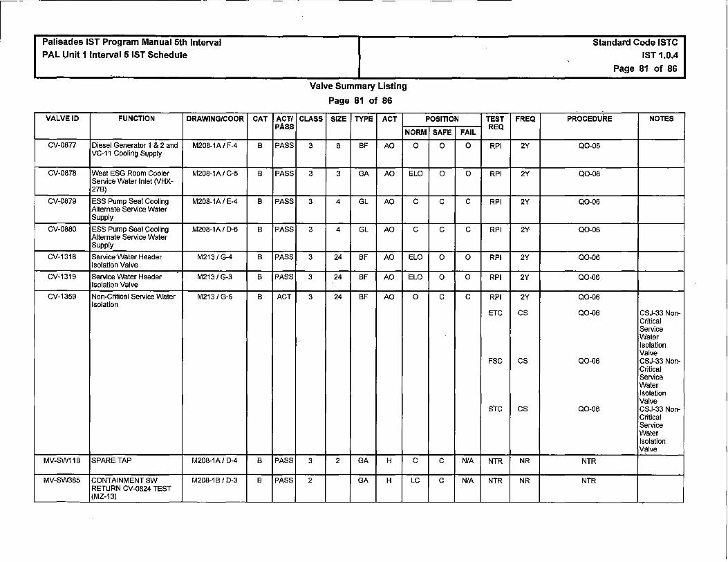
Palisades IST Program Manual 5th Interval PAL Unit 1 Interval 5 IST Schedule
VALVE ID FUNCTION DRAWING/COOR
CV-0877 Diesel Generator 1 & 2 and M208-1A I F-4 VC-11 Cooling Supply
CV-0878 West ESG Room Cooler M208-1A I C-5 Service Water Inlet (VHX-27B)
CV-0879 ESS Pump Seal Cooling M208-1A I E-4 Alternate Service Water Supply
CV-0880 ESS Pump Seal Cooling M208-1A I D-6 Alternate Service Water Supply
CV-1318 Service Water Header M213/G-4 Isolation Valve
CV-1319 Service Water Header M213/G-3 Isolation Valve
CV-1359 Non-Critical Service Water M213 / G-5 Isolation
MV-SW118 SPARE TAP M208-1A I D-4
MV-SW385 CONTAINMENT SW M208-1 BI D-3 RETURN CV-0824 TEST (MZ-13)
CAT ACT/ PASS
B PASS
B PASS
B PASS
B PASS
B PASS
B PASS
B ACT
B PASS
B PASS
Valve Summary Listing
Page 81 of 86
CLASS SIZE TYPE ACT POSITION
NORM SAFE
3 6 BF AO 0 0
3 3 GA AO ELO 0
3 4 GL AO c c
3 4 GL AO c c
3 24 BF AO ELO 0
3 24 BF AO ELO 0
3 24 BF AO 0 c
3 2 GA H c c
2 GA H LC c
TEST FREQ
FAIL REQ
0 RPI 2Y
0 RPI 2Y
c RPI 2Y
c RPI 2Y
0 RPI 2Y
0 RPI 2Y
c RPI 2Y
ETC cs
FSC cs
STC cs
N/A NTR NR
NIA NTR NR
Standard Code ISTC IST 1.0.4
Page 81 of 86
PROCEDURE NOTES
Q0-05
Q0-06
Q0-06
Q0-06
Q0-06
Q0-06
Q0-06
Q0-06 CSJ-33 Non-Critical Service Water Isolation Valve
Q0-06 CSJ-33 Non-Critical Service Water Isolation Valve
Q0-06 CSJ-33 Non-Critical Service Water Isolation Valve
NTR
NTR

Palisades IST Program Manual 5th Interval PAL Unit 1 Interval 5 IST Schedule
VALVE ID FUNCTION DRAWING/COOR
CK-SW401 Service Water Pump P-7A M213 / F-4 Discharge Check
CK-SW402 Service Water Pump P-78 M213 / F-3 Discharge Check
CK-SW403 Service Water Pump P-7C M213 / F-2 Discharge Check
CK-SW410 Containment Air Cooler M208-1B I F-7 VHX-4 Outlet
CV-1805 Containment Purge Air M218-2 / D-6 Exhaust Valve
CV-1806 Containment Purge Air M218-2 / D-6 Exhaust Valve
CV-1807 Containment Purge Air M218-2 / D-6 Exhaust Valve
CV-1808 Containment Purge Air M218-2 / D-6 Exhaust Valve
CAT ACT/ PASS
c ACT
c ACT
c ACT
c ACT
A PASS
A PASS
A PASS
A PASS
Valve Summary Listing
Page 82 of 86
CLASS SIZE TYPE ACT POSITION
NORM SAFE
3 16 CK SA O/C OIC
3 16 CK SA OIC O/C
3 16 CK SA OIC O/C
3 8 CK SA 0 O/C
2 8 BF AO ELC/O c
2 8 BF AO ELC/O c
2 8 BF AO ELC/O c
2 8 BF AO ELC/O c
TEST FREQ
FAIL REQ
NIA eve Q
cvo R
N/A eve Q
cvo R
N/A eve Q
cvo R
N/A eve CM
cvo CM
c RPI 2Y
LTJ AppJ
c RPI 2Y
LTJ AppJ
c RPI 2Y
LTJ AppJ
c RPI 2Y
LTJ AppJ
Standard Code ISTC IST 1.0.4
Page 82 of 86
PROCEDURE NOTES
Q0-14
R0-144 ROJ-05 Service WaterPmps P-7A,B &C Discharge Checks
Q0-14
R0-144 ROJ·05 Service WaterPmps P-7A,B & C Discharge Checks
Q0-14
R0-144 ROJ-05 Service WaterPmps P-7A,B &C Discharge Checks
CMJ-SWS-S-02 CMJ-SWS-S-02
CMJ-SWS-S-02 CMJ-SWS-S-02
Q0-06
R0-032-01A
Q0-06
R0-032-01A
Q0-06
R0-032-01C
Q0-06
R0-032-01C
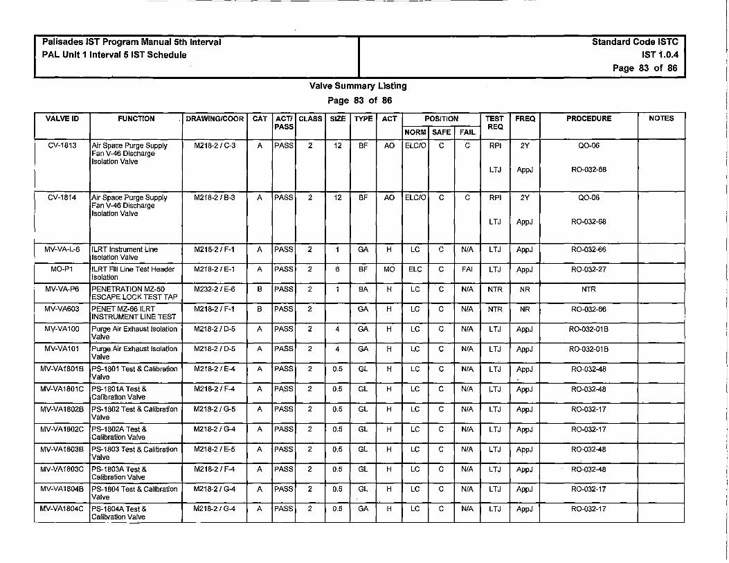
Palisades IST Program Manual 5th Interval PAL Unit 1 Interval 5 IST Schedule
VALVE ID FUNCTION DRAWING/COOR
CV-1813 Air Space Purge Supply M218-2 I C-3 Fan V-46 Discharge Isolation Valve
CV-1814 Air Space Purge Supply M218-2 I B-3 Fan V-46 Discharge Isolation Valve
MV-VA-L-6 ILRT Instrument Line M218-2 I F-1 Isolation Valve
MO-P1 ILRT Fill Line Test Header M218-2 I E-1 Isolation
MV-VA-P6 PENETRATION MZ-50 M232-2 IE-6 ESCAPE LOCK TEST TAP
MV-VA603 PENET MZ-66 ILRT M218-2 I F-1 INSTRUMENT LINE TEST
MV-VA100 Purge Air Exhaust Isolation M218-2 I D-5 Valve
MV-VA101 Purge Air Exhaust Isolation M218-2 I D-5 Valve
MV-VA1801B PS-1801 Test & Calibration M218-2 I E-4 Valve
MV-VA1801C PS-1801A Test & M218-2 I F-4 Calibration Valve
MV-VA1802B PS-1802 Test & Calibration M218-21G-5 Valve
MV-VA1802C PS-1802A Test & M218-2 I G-4 Calibration Valve
MV-VA1803B PS-1803 Test & Calibration M218-2 I E-5 Valve
MV-VA1803C PS-1803A Test & M218-2 I F-4 Calibration Valve
MV-VA1804B PS-1804 Test & Calibration M218-2 I G-4 Valve
MV-VA1804C PS-1804A Test & M218-2 I G-4 Calibration Valve
CAT ACT/ PASS
A PASS
A PASS
A PASS
A PASS
B PASS
B PASS
A PASS
A PASS
A PASS
A PASS
A PASS
A PASS
A PASS
A PASS
A PASS
A PASS
Valve Summary Listing
Page 83 of 86
CLASS SIZE TYPE ACT POSITION
NORM SAFE
2 12 BF AO ELCIO c
2 12 BF AO ELCIO c
2 1 GA H LC c
2 6 BF MO ELG c
2 1 BA H LC c
2 GA H LC c
2 4 GA H LC c
2 4 GA H LC c
2 0.5 GL H LC c
2 0.5 GL H LC c
2 0.5 GL H LC c
2 0.5 GL H LC c
2 0.5 GL H LC c
2 0.5 GL H LC c
2 0.5 GL H LC c
2 0.5 GA H LC c
TEST
FAIL REQ
c RPI
LTJ
c RPI
LTJ
NIA LTJ
FAI LTJ
NIA NTR
NIA NTR
NIA LTJ
NIA LTJ
NIA LTJ
NIA LTJ
NIA LTJ
NIA LTJ
N/A LTJ
NIA LTJ
NIA LTJ
NIA LTJ
FREQ
2Y
AppJ
2Y
AppJ
AppJ
AppJ
NR
NR
AppJ
AppJ
AppJ
-AppJ
AppJ
AppJ
AppJ
AppJ
AppJ
AppJ
Standard Code ISTC
IST 1.0.4
Page 83 of 86
PROCEDURE NOTES
Q0-06
R0-032-68
Q0-06
R0-032-68
R0-032-66
R0-032-27
NTR
R0-032-66
R0-032-01B
R0-032-01B
R0-032-48
R0-032-48
R0-032-17
R0-032-17
R0-032-48
R0-032-48
R0-032-17
R0-032-17

Palisades IST Program Manual 5th Interval PAL Unit 1 Interval 5 IST Schedule
VALVE ID FUNCTION DRAWING/COOR
MV-VA1805A PT-1805 Test & Calibration M218-2 / E-4 Valve
MV-VA1805C PT-1805A Test & M218-2 I E-4 Calibration Valve
MV-VA1812A PT-1812 Test & Calibration M218-2 I G-5 Valve
MV-VA1812C PT-1812 Test & Calibrntion M218-2 I G-4 Valve
MV-VA1814A PT-1814 Test & Calibration M218-2 I F-4 Valve
MV-VA18148 Test & Calibration Tap M218-2 I H-5 Isolation Valve
MV-VA1814F Test Connection to L T-0382 M232-2A I 8-1
MV-VA1814G Test Connection to L T-0382 M232-2A I 8-1
MV-VA1815A PS-1815 Test & Calibration M218-2 I F-5 Valve
MV-VA18158 Test & Calibration Tap M218-2 I F-5 Isolation Valve
MV-VA505 CONT PURGE SUPPLY M218-2 I C-2 TEST CONN (MZ-68)
MV-VA506 CONT PURGE EXHAUST M218-2 I D-6 TEST CONN (MZ-1A)
MV-VA507 PENETRATION MZ-18 M218-2 I D-5 PURGE AIR EXHAUST TEST
MV-VA508 CONT PURGE EXHAUST M218-2 I D-6 TEST CONN (MZ-1C)
MV-VA532 PERSONNEL AIRLOCK M232-1 I G-2 MZ-19 INNER DOOR TEST
MV-VA533 Personnel Airlock MZ-19 M232-1 I G-2 Test Valve
MV-VA601 ILRT Instrument Line M218-2/F-2 Isolation Inside Containment
MV-VA602 PENET MZ-66 ILRT M218-2 I F-1 INSTRUMENT LINE TEST
MV-VA603 ILRT Instrument Line Test M218-2 I F-1 Valve
CAT ACT/ PASS
A PASS
A PASS
A PASS
A PASS
A PASS
A PASS
A PASS
A PASS
A PASS
A PASS
B PASS
B PASS
B PASS
B PASS
B PASS
B PASS
A PASS
B PASS
B PASS
Valve Summary Listing
Page 84 of 86
CLASS SIZE TYPE ACT POSITION
NORM SAFE
2 0.5 GL H LC c
2 0.5 GL H LC c
2 0.5 GL H LC c
2 0.5 GL H LC c
2 0.5 GL H LC c
2 0.5 GL H LC c
2 0.375 GL H LC c
2 0.375 GL H LC c
2 0.5 GL H LC c
2 0.5 GL H LC c
2 1 GL H LC c
2 1 GA H LC c
2 0.5 GL H LC c
2 1 GA H LC c
2 0.25 BA H LC c
2 0.75 GA H LC c
2 1.5 GA H LC c
2 1.5 GL H LC c
2 1.5 GA H LC c
TEST
FAIL REQ
N/A LTJ
NIA LTJ
NIA LTJ
NIA LTJ
NIA LTJ
NIA LTJ
NIA LTJ
NIA LTJ
NIA LTJ
N/A LTJ
N/A NTR
NIA NTR
NIA NTR
NIA NTR
N/A NTR
NIA NTR
NIA LTJ
NIA NTR
N/A NTR
FREQ
AppJ
AppJ
AppJ
AppJ
AppJ
AppJ
AppJ
AppJ
AppJ
AppJ
NR
NR
NR
NR
NR
NR
AppJ
NR
NR
Standard Code ISTC IST 1.0.4
Page 84 of 86
PROCEDURE NOTES
R0-032-48
R0-032-48
R0-032-17
R0-032-17
R0-032-17
R0-032-17
R0-032-52A
R0-032-52A
R0-032-48
R0-032-48
NTR
NTR
NTR
NTR
NTR
NTR
R0-032-66
NTR
R0-032-66
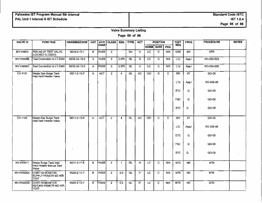
Palisades IST Program Manual 5th Interval PAL Unit 1 Interval 5 IST Schedule
VALVE ID FUNCTION DRAWING/COOR
MV-VA604 PEN MZ-27 TEST VALVE M218-2 / E-1 (LOCKED CLOSED)
MV-VA6068 Test Connection to L T-0383 M232-2A I 8-2
MV-VA606C Test Connection to L T-0383 M232-2A I 8-2
CV-1101 Waste Gas Surge Tank M211-2 / G-7 Inlet Vent Header Valve
CV-1102 Waste Gas Surge Tank M211-2 / G-6 Inlet Vent Header Valve
.
MV-WG511 Waste Surge Tank Inlet M211-2 / F-6 Vent Header Manual Test Valve
MV-WG530A CONT H2 MONITOR M224-2/C-7 SUPPLY PENETR MZ-408 TEST .
MV-WG5308 CONT H2 MONITOR M224-2 / D-7 RETURN PENETR MZ-40A TEST
CAT ACT/ PASS
8 PASS
A PASS
A PASS
A ACT
A ACT
8 PASS
8 PASS
8 PASS
Valve Summary Listing
Page 85 of 86
CLASS SIZE TYPE ACT POSITION
NORM SAFE
2 GA H LC c
2 0.375 GL H LC c
2 0.375 GL H LC c
2 4 GL AO O/C c
2 4 GL AO O/C c
2 1 GL H LC c
2 0.5 GL H LC c
2 0.5 GL H LC c
TEST
FAIL REQ
N/A NTR
N/A LTJ
N/A LTJ
c RPI
LTJ
ETC
FSC
STC
c RPI
LTJ
ETC
FSC
STC
N/A NTR
NIA NTR
N/A NTR
FREQ
NR
AppJ
AppJ
2Y
AppJ
Q
Q
Q
2Y
AppJ
.Q
Q
Q
NR
NR
NR
Standard Code ISTC IST 1.0.4
Page 85 of 86
PROCEDURE NOTES
NTR
R0-032-528
R0-032-528
Q0-05
R0-032-46
Q0-05
Q0-05
Q0-05
Q0-05
R0-032-46
Q0-05
Q0-05
Q0-05
NTR
NTR
NTR

Palisades IST Program Manual 5th Interval PAL Unit 1 Interval 5 IST Schedule
VALVE ID FUNCTION DRAWING/COOR
MV-WG531A CONT H2 MONITOR M224-2 / F-7 SUPPLY PENETR MZ-21A TEST
MV-WG531B CONT H2 MONITOR M224-2/ G-7 RETURN PENETR MZ-21 TEST
CAT ACT/ PASS
B PASS
B PASS
Valve Summary Listing
Page 86 of 86
CLASS SIZE TYPE ACT POSITION
NORM SAFE
2 0.5 GL H LC c
2 0.5 GL H LC c
TEST
FAIL REQ
N/A NTR
N/A NTR
FREQ
NR
NR
Standard Code ISTC IST 1.0.4
Page 86 of 86
PROCEDURE NOTES
NTR
NTR

Palisades Nuclear Plant lnservice Testing (IST) Program Plan
Fifth Ten-Year Interval
Section 3.0
SEP-CV-PLP-002
Check Valve Condition Monitoring And
lnservice Testing Program
Page 148
( 45 pages follow)

Program Section No. SEP-CV-PLP-002 Revision 3
Page 1 of45
CHECK VALVE CONDITION MONITORING AND INSERVICE TESTING PROGRAM
ENGINEERING NUCLEAR ENGINEERING PROGRAMS
APPLICABLE SITES
All Sites: D
Specific Sites: ANO D GGNS D IPEC D JAF D PLP !XI PNPS D RBS D VY D W3 D HQN D
Current Revision
3
1
Safety Related: Yes No
Program Section Revision Summary Description of Change
Revised the Program Section to reflect the 10 year code update from The ASME OM Code 2001 Edition through 2003 Addenda to the 2004 Edition through the 2006 Addenda. Current: Revision 2 issued in order to reflect the cancellation of RT-122.
Previous: Revision 1 issued in order to reflect INPO's change from the EPIX and the Nuclear Network to INPO Consolidated Event System (ICES).
Revision 0 Transitioned from Palisades Engineering Manual EM-09-18, Revision 7, "CHECK VALVE CONDITION MONITORING AND INSERVICE TESTING PROGRAM".
REFERENCE USE
• Procedure and Procedure Precautions and Limitations are at the work location for reference.
• Review and understand segments before performing any steps.
• Signoff steps are completed, when included, before starting the next step.
• Place keep in accordance with EN-HU-102, "Human Performance Tools."
• Review the Procedure to verify segments have been completed.

Program Section Title:
Program Section No. SEP-CV-PLP-002 Revision 3
Page 2 of 45
CHECK VALVE CONDITION MONITORING AND INSERVICE TESTING PROGRAM
Prepared By: G Katt )} (A"' rPJt- Date: 'b/1!))/b
Checked By: R White RM'kk/~ Date: '3--l'Yt6
Reviewed By: Date: (Optional)
ANll: N/A Date: N/A
(Reviewed By or N/A)
Concurred: :JI"\ Tt..rt_ !fL /fl 1a Date: '3jts/1~
Responsible Supervisor

SECTION PAGE NO. Main Body All
Attachment 1 All Attachment 2 All Attachment 3 All Attachment 4 All Attachment 5 All Attachment 6 All
REVISION 3 3 3 3 3 3 3
Program Section No. SEP-CV-PLP-002 Revision 3
Page 3 of45

Table of Contents
Program Section No. SEP-CV-PLP-002 Revision 3
Page4 of 45
1.0 PURPOSE ..................................................................................... ~ ................................ 6
2.0 SCOPE ........................................................................................................................... 6
3.0 REFERENCES ............................................................................................................... 7
3.1 SOURCE DOCUMENTS ................................................................................ 7
3.2 REFERENCE DOCUMENTS ......................................................................... 9
4.0 DEFINITIONS AND RESPONSIBILITIES .................................................................... 12
4.1 DEFINITIONS ............................................................................................... 12
5.0 PROCEDURE ............................................................................. · ............................•..... 16
5.1 PROGRAM DESCRIPTION ......................................................................... 16
5.2 REGULATIONS AND CODES ..................................................................... 17
5.2.1 10 CFR 50.55a, "Codes and Standards" .............................. 17
5.2.2 Code of Federal Regulation 1 OCFR50.55a(b)(3)(iv) Modifications to Appendix II, "Check Valve Condition Monitoring Program" ............................................................ 17
5.2.3 ASME/ANSI Code for Operation and Maintenance of Nuclear Power Plants ........................................................... 17
5.2.4 ASME OM Code Interpretations ........................................... 17
5.2.5 Technical Position Statements ............................................ 18
5.2.6 Regulation and Code Updates ............................................. 18
5.2.7 Relief Requests ..................................................................... 18
5.3 PLANT PROCEDURES ............................................................................... 18
5.3.1 Related Procedures and Specifications .............................. 18
5.3.2 Procedure Development ....................................................... 19
5.3.3 Check Valve Testing Program Procedures ......................... 19
5.3.4 Check Valve Implementing Procedures and Processes .... 19
5.4 CATEGORIZATION OF CHECK VALVES .................................................. 20
5.5 APPENDIX II, CONDITION MONITORING (CM) REQUIREMENTS ........... 20
5.5.1 CM Check Valve Groupings ................................................. 20
5.5.2 Analysis of CM Test and Maintenance Activities ............... 21
5.5.3 CM Activities ......................................................................... 22
5.5.4 Condition Monitoring Analysis (CMA) ................................. 23
5.5.5 Implementation and Review of CM Activities ..................... 24

Table of Contents
Program Section No. SEP-CV-PLP-002 Revision 3
Page 5 of45
5.5.6 CM Corrective Maintenance ................................................. 25
5.5.7 Required Records for CM ..................................................... 25
5.6 SUBSECTION ISTC, CHECK VALVE INSERVICE TESTING (IST) REQUIREMENTS ......................................................................................... 25
5.6.1 Type of Testing Required for Check Valve Categories ...... 25
5.6.2 Grouping Check Valves for Testing .................................... 26
5.6.3 Intervals for Testing Valves ........................................... : ..... 27
5.6.4 Scheduling Valve lnservice Tests ........................................ 28
5.6.5 Criteria for Accepting Test Results ..................................... 29
5.6.6 Acceptance Criteria Outside of Code Allowed ................... 30
5.6.7 Valve Failure and Corrective Action .................................... 31
5.7 TRENDING .................................................................................................... 32
6.0 ATTACHMENTS AND RECORDS ............................................................................... 33
6.1 ATTACHMENTS .......................................................................................... 33
6.2 RECORDS ................................................................................................... 33
7.0 SPECIAL REVIEWS .................................................................................................... 33
ATTACHMENTS ·
Attachment 1, "Cold Shutdown Justification Index" Attachment 2, "Refueling Outage Justification Index" Attachment 3, "Relief Request Justification Index" Attachmer:it 4, "Condition Monitoring Analysis Form" Attachment 5, "Folder Checklist" Attachment 6, "Appendix II Program Flow Chart"

1.0 PURPOSE
Program Section No. SEP-CV-PLP-002 Revision 3
Page 6 of 33
1.1 To describe how the Palisades Check Valve Condition Monitoring (CM) Program satisfies the regulatory requirements of Title 10 of the Code of Federal Regulations, Part 50, Section 55a (10 CFR 50.55a, "Codes and Standards") and Technical Specifications ADMIN 5.5.7.
1.2 This procedure establishes the requirements for implementing and maintaining a Check Valve Condition Monitoring Program per the Code for Operations and Maintenance of Nuclear Power Plants, 2004 Edition with Addenda through 2006, Appendix II, "Check Valve Condition Monitoring Program."
1.3 This procedure identifies regulatory, code, and guidance documents that provide specific requirements (including scope, categorization, type and methods of testing, acceptance criteria, corrective actions, and documentation) and guidance (including grouping valves, nonintrusive testing techniques, and requests for regulatory relief) for the CM Program.
1.4 To outline the process of scheduling tests, testing valves, evaluating test results, taking corrective actions, trending test results, and documenting valve information pertinent to the Palisades CM Program.
2.0 SCOPE
2.1 This procedure is developed to the requirements (with exception of the relief requests) of 10 CFR 50.55a which incorporates by reference the Code for Operations and Maintenance of Nuclear Power Plants, 2004 Edition with Addenda through 2006, otherwise identified in this procedure as the Code.
The requirements of these regulations and codes became effective on March 24, 2016, which is the beginning date of the 5th lnservice Test Interval. They will remain in effect through Palisades' fifth 120-month interval ending March 23, 2026.
2.2 This procedure applies to ASME Class 1, 2, and 3 check valves as specified in 10 CFR 50.55a and in Technical Specifications ADMIN 5.5.7. The Code of Federal Regulation (10 CFR 50.55a(f)(4)) requires valves that are classified as ASME Code Class 1, 2, and 3 to be tested in accordance with the Code.
2.3 This procedure may be applicable to Non-Class valves, including:
a. Certain check valves that are outside the scope of the Code but have Technical Specifications Surveillance Testing Requirements.
b. Certain check valves that are outside the scope of the Code but have a specific function in shutting down the reactor to Technical Specification Mode 5 or in mitigating the consequences of an accident.

Program Section No. SEP-CV-PLP-002 Revision 3
Page7 of 33
c. Certain check valves that are outside the scope of the Code, but are deemed important to test.
d. Certain check valves that are outside of the Code, but are tested in accordance with commitments Palisades has made with the NRC.
2.4 The test requirements for all other ASME Class 1, 2, or 3 valves are described in SEP-PLP-IST-101, "lnservice Test of Plant Valves." Reference SEP-PLP-IST-101 for a description of the relationships between codes and standards, the code of federal regulation, technical specification, condition monitoring, inservice testing and plant implementing procedures.
2.5 When requirements of the Code and Technical Specifications conflict, either the Technical Specifications shall be changed, or the provisions of the more stringent program shall be followed.
2.6 Program Section SEP-ISl-PLP-002, "ASME Code Boundaries for ASME Section XI lnservice Inspection Program", provides the ASME boundary classifications for valves, and references the Color Coded P&IDs as a visible means of identifying what we have committed to as the plant Code Boundaries.
2.7 Plant check valves that are in scope are identified in the lddeal Concepts Software Suite®.
2.8 Per Subsection ISTC-1200 of the OM Code, the following are excluded from the IST Program requirements provided that they are not required to perform a specific safety function:
a. Valves used only for operating convenience, such as vent, drain, and instrument and test valves.
b. Valves used only for system control, such as, pressure regulating, temperature control and flow control and without a safety related fail safe function.
c. Valves used only for system or component maintenance.
d. Skid mounted equipment adequately tested during testing of the larger skid components.
3~ REFERENCES
3.1 SOURCE DOCUMENTS
3.1.1 Technical Specifications SR 3.0.1, SR 3.0.2, SR 3.0.3, SR 3.0.4, SR 3.3.7.2

'
L
Program Section No. SEP-CV-PLP-002 Revision 3
Page 8 of 33
3.1.2 Technical Specifications ADMIN 5.5.7
3.1.3 Technical Specifications Bases Table B 3.4.14-1
3.1.4 Final Safety Analysis Report - 6.9.2.2
3.1.5 Entergy Quality Assurance Program Manual (QAPM)
3.1.6 Code of Federal Regulations Title 10, Part 50, Section 55a (10 CFR 50.55a), "Codes and Standards"
3.1.7 Code of Federal Regulations Title 10, Part 50 (10 CFR 50), Appendix J, "Primary Reactor Containment Leakage Testing for Water-Cooled Reactors"
3.1 .8 ASME OM Code 2004 Edition with Addenda Through 2006, Operations and Maintenance of Nuclear Power Plants, Subsection ISTA, ISTC and Appendix II, "Check Valve Condition Monitoring"
3.1.9 USNRC NUREGs, Generic Letters, Information Notices, and IE Bulletins
a. Generic Letter 87-06, "Periodic Verification of Leak Tight Integrity of Pressure Isolation Valves" (3621/1538)
b. Information Notice 88-70, "Check Valve lnservice Testing Program Deficiencies" (C/F - 3758/1494)
c. Nuclear Energy Institute (NEI) White Paper entitled, "Standard Format for Requests from Commercial Reactor Licensees Pursuant to 10 CFR 50.55a, Revision 1," dated June 7, 2004 (ADAMS Accession No. ML070100400)
d. Information Notice 2000-21, "Detached Check Valve Disc Not Detected By Use of Acoustic and Magnetic Nonintrusive Test Techniques"
. e. Memorandum: Summary of Public Workshops Held in NRC Regions on Inspection Procedure 73756, "lnservice Testing of Pumps and Valves," and Answers to Panel Questions on lnservice Testing Issues, Joseph Colaccino, July 18, 1997
3.1.10 Miscellaneous Correspondence
3.1.11
a. NRC Order dated April 20, 1981 regarding Event V PIVs (C/F - 9018/1126)
Other Codes, Standards, and Guides
a. ANSI/ANSI 51.1, 1983, "American National Standard Nuclear Safety Criteria for the Design of Stationary Pressurized Water Reactor Plants"

Program Section No. SEP-CV-PLP-002 Revision 3
Page 9 of 33
b. Regulatory Guide 1.26, "Quality Group Classifications and Standards for Water, Steam and Radioactive Waste Containing Components of Nuclear Power Plants"
c. ANSI N45.2.6, 1978, "Qualifications of Inspection, Examination and Testing Personnel for Nuclear Power Plants"
d. ANSI N18.7, "Administrative Controls and Quality Assurance for Operational Phase of Nuclear Power Plants"
3.1.12 Plant Equipment Data Base (EDB)
3.1.13 Plant Piping and Instrument Diagrams (P&IDs)
3.2 REFERENCE DOCUMENTS
3.2.1 Final Safety Analysis Report - 5.1.6.6 and 6.9.2.2
3.2.2 Palisades Administrative Procedures:
a. 3.19, ''Technical Specifications Programs"
b. 5.19, "Post Maintenance Testing"
c. 9.20, "Technical Specification Surveillance and Special Test Program"
d. 10.51, "Writer's Guideline for Site Procedures"
3.2.3 Engineering Procedures
a. SEP-PLP-IST-101, "lnservice Testing of Plant Valves"
b. SEP-ISl-PLP-001, "lnservice Inspection"
c. SEP-CV-PLP-001, "Check Valve Program"
d. EN-DC-334, "Primary Containment Leakage Rate Testing (Appendix J)"
e. SEP-ISl-PLP-002, "ASME Code Boundaries for ASME Section XI lnservice Inspection Program"
3.2.4 Permanent Maintenance Procedures
a. MSl-1-14, "Nonintrusive Diagnostic Check Valve Test Procedure"
b. MSl-1-16, "Nonintrusive Diagnostic Valve Test Procedure (Using Viper/UDS Platform)"

Program Section No. SEP-CV-PLP-002 Revision 3
Page 10 of 33
3.2.5 Technical Specification Surveillance Procedures
a. Q0-6, "Cold Shutdown Valve Test Procedure (Includes Containment Isolation Valves)"
b. Q0-8B, "LPSI Check Valve Operability Test and LPSI Motor Operated Valve Open Stop Verification Test (Modes 5 and 6)"
c. X0-11, "Containment Isolation Check Valve Test"
d. Q0-14, "lnservice Test Procedure - Service Water Pumps"
e. Q0-15, "lnservice Test Procedure - Component Cooling Water Pumps"
f. Q0-16, "lnservice Test Procedure - Containment Spray Pumps"
g. Q0-19, "lnservice Test Procedure - HPSI Pumps and ESS Check Valve Operability Test"
I
h. Q0-20, "lnservice Test Procedure - Low Pressure Safety Injection Pumps"
i. Q0-21, "lnservice Test Procedure, Auxiliary Feedwater Pumps"
j. Q0-24, "Verify Closure of Main Feedwater Check Valves"
k. Q0-32, "Closure Verification of HPSI Train 2 and LPSI Injection Check Valves"
I. Q0-37, "Main Steam Isolation and Bypass Valve Testing"
m. Rl-17, "Main Steam Isolation Valve Circuits Test and Valve Closure Testing"
n. R0-32, "LLRT - Local Leak Rate Test Main Procedure"
o. R0-65, "High Pressure Safety Injection (HPSI) Trains 1 and 2, and Hot Leg Injection (HLI) Check Valve Test and Cold Leg/Hot Leg Flow Balance Test"
p. R0-98, "LPSI and Containment Spray Comprehensive Pump Test and Check Valves Test"
q. R0-105, "Full Flow Test For SIT Check Valves and PCS Loop Check Valves"
r. R0-141, "Containment Sump Check Valves lnservice Test"
s. R0-143, "Nonintrusive Testing of Charging Header Check Valves"

Program Section No. SEP-CV-PLP-002 Revision 3
Page 11of33
t. R0-144, "Comprehensive Pump Test Procedure Service Water Pumps P-7A, P-78 and P-7C"
u. R0-145, "Comprehensive Pump Test Procedure Auxiliary Feedwater Pumps P-8A, P-88 and P-8C"
v. R0-146, "Comprehensive Pump Test Procedure - Component Cooling Water Pumps P-52A, P-528 and P-52C"
w. R0-147, "Comprehensive Pump Test Procedure - HPSI Pumps P-66A and P-668 and ESS Check Valve Operability Test"
x. RT-71 L, "Technical Specification ADMIN 5.5.2 Pressure Test of ESS Pump Suction Piping"
y. SH0-1, "Operator's Shift Items Modes 1, 2, 3, and 4"
z. S0-9, "Primary Coolant System Pressure Isolation Check Valves"
3.2.6 Entergy Procedures
a. EN-DC-131, "Check Valve Maintenance and Monitoring Program"
b. EN-PL-155, "Change Management Policy" (History)
c. EN-OP-104, "Operability Determination Process"
d. EN-WM-100, "Work Request (WR) Generation, Screening and Classification"
e. EN-WM-105, "Planning"
f. EN-DC-324, "Preventive Maintenance Program"
g. EN-AD-103, "Document Control and Records Management Programs"
h. EN-HU-102, "Human Performance Tools"
i. EN-DC-334, "Primary Containment Leakage Rate Testing (Appendix J)"
3.2. 7 Other Procedures
a. Preoperational Test Procedure #12, "Engineered Safeguards System and Shutdown Cooling System"
b. Entergy Procedure EN-Ll-102, "Corrective Action Process"

3.2.8 Periodic Activities
Program Section No. SEP-CV-PLP-002 Revision 3
Page 12 of 33
a. PMID 50083261, "CK-CD407, Nonintrusive Check Valve Test"
b. PMID 50083415, "CK-DMW400, Nonintrusive Check Valve Test"
c. PMID 50080969, "CK-ES3340, Disassemble, Inspect and Repair Check Valve"
d. PMID 50081298, "Exercise CK-SW410 VHX-4 Outlet Check Valve"
3.2.9 Miscellaneous References
a. Facility Change FC-441, Hot Leg Injection (0869/0536 and 9126/0004)
b. Entergy Procedure EN-WM-101, "On-Line Work Management Process"
c. lddeal Concepts Software Suite®
d. Check Valve Program, "Check Valves at Palisades," (Condition Monitoring database)
e. Nuclear Industry Check (NIC) Valve Group Web Page, www.checkvalve.org
4.0 DEFINITIONS AND RESPONSIBILITIES
4.1 DEFINITIONS
4.1 Additional definitions applicable to valve inservice testing are found in the Code.
4.2 Baseline Test - The initial test of a check valve's safety function,. using nonintrusive testing (NIT) techniques that subsequent tests will be assessed against. A Baseline Test shall only be established when/after the check valve is known to be operating acceptably.
4.3 Condition Monitoring Analysis (CMA) - The CMA establishes the basis for specifying inservice testing, examination and preventive maintenance activities for a specific check valve component or check valve group.

Program Section No. SEP-CV-PLP-002 Revision 3
Page 13 of 33
4.4 Condition Monitoring Program - The Condition Monitoring Program is an alternative to the check valve inservice testing program described in Subsection ISTC of the OM Code. The purpose of this program is both to improve valve performance and to optimize testing, examination, and preventive maintenance activities in order to maintain the continued acceptable performance of a selected group of check valves.
4.5 Condition Monitoring Program Test Plan - The Condition Monitoring Program Test Plan conforms to the requirements of the OM Code, Appendix II, Paragraph II 6000, "Documentation" and includes the following elements:
a. A list of valves in the program.
b. A list of valves in each valve· group.
c. Dates valves were added to or deleted from the program and the reason for their addition or deletion.
d. Analyses forming the basis of the program.
e. Identified failure or maintenance history patterns for each check valve.
f. Condition monitoring program activities, including the trended attributes and the bases for the associated intervals for each valve or valve group.
4.6 IST Coordinator
a. Develops and administers the IST program for Plant valves.
b. Review and trend check valve IST results, notifying the Check Valve Program Engineer of any abnormal or erratic trends with check valves within the scope of SEP-CV-PLP-002, "Check Valve Condition Monitoring and lnservice
·Testing Program."
c. Ensures the necessary condition monitoring analyses (CMA) reviews and changes are properly performed, approved, and documented.
d. Tracks action plans and activities to completion for the condition monitoring program.
e. Provides Code and regulatory expertise for CMAs performed per this procedure.

4. 7 System Engineer
Program Section No. SEP-CV-PLP-002 Revision 3
Page 14 of 33
a. Acts as the service manager for assigned system(s).
b. Responsible for the maintenance and operating aspects of tested equipment.
c. Coordinates system activities including maintenance, testing, Appendix J requirements, and monitoring for the CM program.
d. Provides system expertise for CMAs performed, when requested.
4.8 Component Engineer (Check Valves)
a. Reviews the results of inspections, non-intrusive testing and corrective maintenance actions for check valves in the condition monitoring program.
b. Provides technical direction and condition monitoring feedback for the CMAs performed.
c. Provides component expertise for CMAs performed per this procedure.
4.9 CMA Reviews and Approvals
4.9.1 CMA Review Panel generally consists of combination of the following individuals:
a. IST Program Engineer
b. Check Valve Program Engineer
c. System Engineer
d. Operations Representative
e. PSA Group Representative
f. Others at the discretion of the IST Program Engineer
4.9.2 Approvers ensure that an acceptable basis exists to justify the selected testing strategy and that the tests, examinations, and preventive maintenance activities are in keeping with ALARA and industrial safety practices, and that cost savings are optimal.
4.9.3 Approvers ensure that the selected trend param~ters or data analysis techniques are adequate to monitor valve condition.
4.10 Technical Specification Surveillance Program Administrator (TSSPA) - responsible to oversee scheduling and administrative performance of the required Technical Specification Surveillance Test.
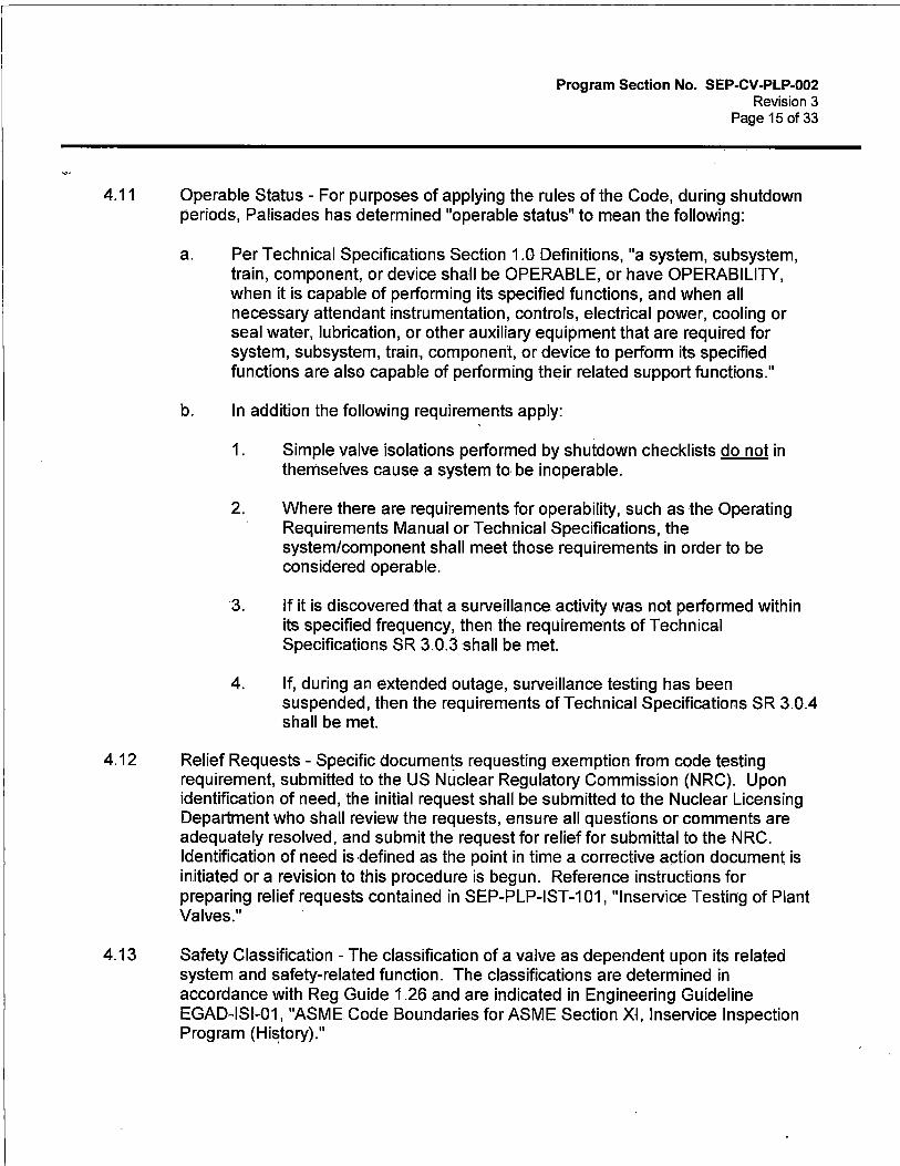
Program Section No. SEP-CV-PLP-002 Revision 3
Page 15 of 33
4.11 Operable Status - For purposes of applying the rules of the Code, during shutdown periods, Palisades has determined "operable status" to mean the following:
a. Per Technical Specifications Section 1.0 Definitions, "a system, subsystem, train, component, or device shall be OPERABLE, or have OPERABILITY, when it is capable of performing its specified functions, and when all necessary attendant instrumentation, controls, electrical power, cooling or seal water, lubrication, or other auxiliary equipment that are required for system, subsystem, train, component, or device to perform its specified functions are also capable of performing their related support functions."
b. In addition the following requirements apply:
1. Simple valve isolations performed by shutdown checklists do not in themselves cause a system to be inoperable.
2. Where there are requirements for operability, such as the Operating Requirements Manual or Technical Specifications, the system/component shall meet those requirements in order to be considered operable.
3. If it is discovered that a surveillance activity was not performed within its specified frequency, then the requirements of Technical Specifications SR 3.0.3 shall be met.
4. If, during an extended outage, surveillance testing has been suspended, then the requirements of Technical Specifications SR 3.0.4 shall be met.
4.12 Relief Requests - Specific documents requesting exemption from code testing requirement, submitted to the US Nuclear Regulatory Commission (NRC). Upon identification of need, the initial request shall be submitted to the Nuclear Licensing Department who shall review the requests, ensure all questions or comments are adequately resolved, and submit the request for relief for submittal to the NRC. Identification of need is defined as the point in time a corrective action document is initiated or a revision to this procedure is begun. Reference instructions for preparing relief requests contained in SEP-PLP-IST-101, "lnservice Testing of Plant Valves."
4.13 Safety Classification - The classification of a valve as dependent upon its related system and safety-related function. The classifications are determined in accordance with Reg Guide 1 .26 and are indicated in Engineering Guideline EGAD-ISl-01, "ASME Code Boundaries for ASME Section XI, lnservice Inspection Program (Hi~tory)."

Program Section No. SEP-CV-PLP-002 Revision 3
Page 16 of 33
4.14 Valve Is Known To Be Operating Acceptably - It is the owner's responsibility to verify that a check valve is operating acceptably before reference values are established, and before or concurrent with Baseline testing. Also, the method(s) used for this verification is the owner's responsibility.
1f a check valve is being assigned a new safety function and only NIT technologies are being used for verification of that function, a minimum of two NIT technologies shall be used to verify that a valve is operating acceptably. Based on NRG Information Notice 2000-21, Palisades has determined that it is NOT acceptable to solely use acoustic NIT to establish that "the valve is known to be operating acceptably." One or a combination of the methods shall.be used to provide "positive proof' (vs, "reasonable assuredness") that the check valve internals are intact (eg, leak testing, differential pressure, reverse flow, radiography, ultrasonics).
4.15 Abbreviations CM - Condition Monitoring PSA - Probabilistic Safety Assessment CMA - Condition Monitoring Analysis OCMA - Optimization of Condition Monitoring Activities PIA - Performance Improvement Activities
4.16 CM Program - Attachment 6, "Appendix 11 Program Flow Chart," provides a process flow diagram for the CM program (adapted from the OM Part 22 Working Group's attempt at diagramming Appendix II). The CM Program is a process driven by Appendix II, which integrates predictive and preventive maintenance practices, and the current prescriptive test requirements, to monitor check valve condition and improve valve performance and reliability.
5.0 PROCEDURE
5.1 PROGRAM DESCRIPTION
The Palisades Check Valve Condition Monitoring Program is designed to satisfy the requirements of the Code of Federal Regulations 10 CFR 50.55a, "Codes and Standards" and Technical Specifications ADMIN 5.5.7. The requirements for implementing and maintaining a Check Valve Condition Monitoring Program per the OM Code 2004 Edition with Addenda through 2006, Appendix II, "Check Valve Condition Monitoring Program" are contained in this section.
SEP-CV-PLP-002 does r:10t apply to other valves in the IST Program such as power operated, relief, and etcetera.

5.2 REGULATIONS AND CODES
5.2.1 10 CFR 50.55a, "Codes and Standards"
Program Section No. SEP-CV-PLP-002 Revision 3
Page 17 of 33
This procedure applies to ASME Class 1, 2, and 3 check valves as specified in 10 CFR 50.55a and in Technical Specifications ADMIN 5.5.7. The Code of Federal Regulation (10 CFR 50.55a(f)(4)) requires valves that are classified as ASME Code Class 1, 2, and 3 to be tested in accordance with the Code.
The Code of Federal Regulations (CFR) is a "living document" that is revised on a periodic basis. The current Palisades Check Valve Condition Monitoring Program is established based on the edition in place as of March 2015. Title 10 of the Code of Federal Regulations, Part 50, Section 55a, requires that each licensee of a nuclear power facility have a program as described in paragraph (f), (ie, 10 CFR 50.55a(f)).
5.2.2 Code of Federal Regulation 1 OCFR50.55a(b)(3)(iv) Modifications to Appendix II, "Check Valve Condition Monitoring Program"
None
5.2.3 ASME/ANSI Code for Operation and Maintenance of Nuclear Power Plants
The ASME/ANSI OM Code is also a "living document" that is revised on a periodic basis. The OM Code also has addenda that are approved on a more frequent interval and editions that incorporate desired addenda, updated on a less frequent interval.·
The current Palisades Check Condition Monitoring Program is established based on . ASME OM Code 2004 Edition with Addenda through 2006, Operations and Maintenance of Nuclear Power Plants, Subsection ISTC, "lnservice Testing of Valves in Light Water Reactor Power Plants." Subsection ISTC, allows as an alternative, a check valve test program in accordance with Appendix II, "Check Valve Condition Monitoring Program."
5.2.4 ASME OM Code Interpretations
Presently, there are no ASME OM Code interpretations used in the valve inservice test program. In the case where interpretations are incorporated, they will be discussed in the applicable section of this procedure.
In some cases ASME has issued interpretations to clarify the requirements or the intent of Code specifications. Interpretations provide valuable direction for implementation of an inspection program.

5.2.5 Technical Position Statements
Program Section No. SEP-CV-PLP-002 Revision 3
Page 18 of 33
In some cases, items such as Code rules and interpretations, 10 CFR 50 rules and industry standards are subject to interpretation and, therefore, require further clarification on their implementation and use. Position statements and clarifications
· developed for the program will be included in the applicable sections.
5.2.6 Regulation and Code Updates
Requirements within the Code of Federal Regulations change as revisions occur. However, the new requirements may not be effective immediately upon the revision date; certain amounts of time are usually allowed to implement new requirements.
10 CFR 50.55a(f)(4) requires licensees to update their CM testing program every 120 months. The program is to be updated to include the requirements of the latest test Code, approved for incorporation by reference by the Director of the Federal Register, in 10 CFR 50.55a(b)(3), including limitations and modifications. The latest test Code is the Code that is referenced in 10 CFR 50.55a(b)(3) twelve (12) months before the start of the licensees next 120 month interval (reference 10 CFR 50.55a(f)(4)(ii)).
The Palisades Plant CM Program Code of record will be in effect through the fifth 120-month interval (March 2016 through March 2026) and will be updated in accordance with 10 CFR 50.55a (f).
5.2. 7 Relief Requests
If Code requirements cannot be met, then a Relief Request shall be submitted for approval to the NRC in accordance with SEP-PLP-IST-101, "lnservice Testing of Plant Valves." NUREG-1482, "Guidelines for lnservice Testing at Nuclear Power Plants," Section 2.5, "Relief Requests and Proposed Alternatives" and Nuclear Energy Institute (NEI) White Paper entitled, "Standard Format for Requests from Commercial Reactor Licensees Pursuant to 10 CFR 50.55a, Revision 1," dated June 7, 2004 (ADAMS Accession No. ML070100400)
5.3 PLANT PROCEDURES
5.3.1 Related Procedures and Specifications
The following documents require a check valve test program:
a. Technical Specifications, ADMIN 5.5.7, "lnservice Testing Program"
b. Palisades Administrative Procedure 3.19, "Technical Specifications Programs"
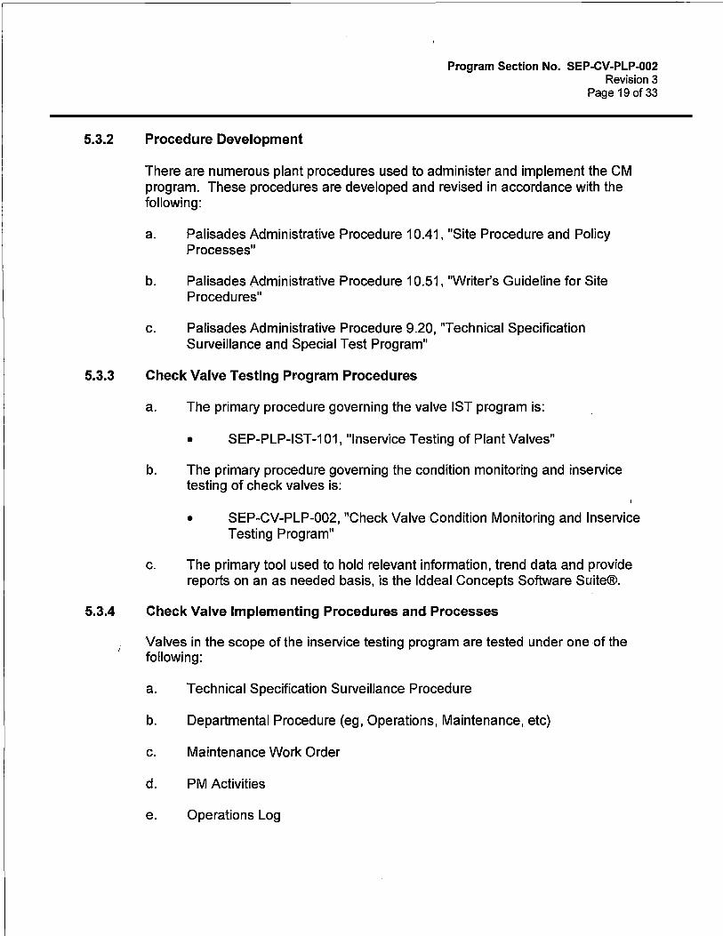
5.3.2 Procedure Development
Program Section No. SEP-CV-PLP-002 Revision 3
Page 19 of 33
There are numerous plant procedures used to administer and implement the CM program. These procedures are developed and revised in accordance with the following:
a. Palisades Administrative Procedure 10.41, "Site Procedure and Policy Processes"
b. Palisades Administrative Procedure 10.51, "Writer's Guideline for Site Procedures"
c. Palisades Administrative Procedure 9.20, "Technical Specification Surveillance and Special Test Program"
5.3.3 Check Valve Testing Program Procedures
a. The primary procedure governing the valve IST program is:
• SEP-PLP-IST-101, "lnservice Testing of Plant Valves"
b. The primary procedure governing the condition monitoring and inservice testing of check valves is:
• SEP-CV-PLP-002, "Check Valve Condition Monitoring and lnservice Testing Program"
c. The primary tool used to hold relevant information, trend data and provide reports on an as needed basis, is the lddeal Concepts Software Suite®.
5.3.4 Check Valve Implementing Procedures and Processes
Valves in the scope of the inservice testing program are tested under one of the following:
a. Technical Specification Surveillance Procedure
b. Departmental Procedure (eg, Operations, Maintenance, etc)
c. Maintenance Work Order
d. PM Activities
e. Operations Log

Program Section No. SEP-CV-PLP-002 Revision 3
Page 20 of 33
5.4 CATEGORIZATION OF CHECK VALVES
In accordance with the ASME Code for Operation and Maintenance of Nuclear Power Plants (ASME OM, Subsection ISTC-1300), check valves within the scope shall be placed in one or both of the following categories. When more than one distinguishing category characteristic is applicable, all requirements of each of the individual categories are applicable, although duplication or repetition of common testing requirements is not necessary.
a. Category A -
b .. Category C -
Valves for which seat leakage is limited to a specific maximum amount in the closed position for fulfillment of their required safety function(s),
Valves which are self-actuating in response to some system characteristic, such as pressure (relief valves) or flow direction (check valves) for fulfillment of the required safety function(s),
The categorization of each check valve in scope to the CM program is contained in the lddeal Concepts Software Suite®.
5.5 APPENDIX II, CONDITION MONITORING (CM) REQUIREMENTS
5.5.1 CM Check Valve Groupings
a. The technical justification for each check valve grouping will be maintained as part of the Check Valve Program. The following requirements apply and must be documented for each grouping. Use the guidance from Attachment 4, "Condition Monitoring Analysis Form," and enter the data into the Check Valve Program Microsoft Access database.
1. Type of activity of the condition monitoring program in regards to performance improvement or optimization of testing, examination, and preventive maintenance activities.
2. Stated reason for analysis.
3. List of applicable references used in the analysis.
4. Analysis of test, maintenance and modification activities.
5. Valve manufacturer, size, materials, orientation, design, application and service conditions of the group.
Program Section No. SEP-CV-PLP-002 Revision 3
Page 21of33
6. Any other bases for the grouping, such as, potential flow instabilities, degree of required disassembly and the need for tolerance or critical dimension checks.
b. See Section 5.6.2 for related criteria for check valve grouping.
5.5.2 Analysis of CM Test and Maintenance Activities
An evaluation of test and maintenance histories of a valve or group of valves to establish the basis for specifying the inservice testing, examination, and preventive maintenance activities will be performed. Use the format and guidance of Attachment 4, "Condition Monitoring Analysis Form," and enter the data into the Check Valve Program Microsoft Access database. The analysis shall include the following as a minimum:
a. Identification of any common failure or maintenance patterns using available plant and industry data sources such as Nuclear Industry Check Valve Group's failure data templates of specific valve vendors, INPO's general database of reported failures, work order history, previous corrective actions, etc.
b. Evaluation of these patterns to determine their significance and potential failure mechanisms. This analysis will include the following, as a minimum:
1. A determination and justification if preventive maintenance activities would mitigate the identified failure mechanism(s) or pattern(s).
2. A determination and justification if condition monitoring tests which are feasible and that would effectively detect and monitor the identified failure mechanism(s).
3. A decision and justification on whether or not periodic disassembly and examination activities would be effective in. monitoring for the identified failure mechanism(s).
4. A decision and justification on whether or not changes in the valve groupings are needed; this is required for both the initial group selection, and for the established group continuation.
c. If this analysis is sufficient (data and justification exists to establish the initial IST intervals for condition monitoring activities), then the activities of Step 5.5.3a must be performed. If this analysis is not sufficient (data and justification are not currently available to complete this analysis), or is inconclusive, or if the basis lacks technical justification, then Step 5.5.3b must be preformed for CM program check valves.
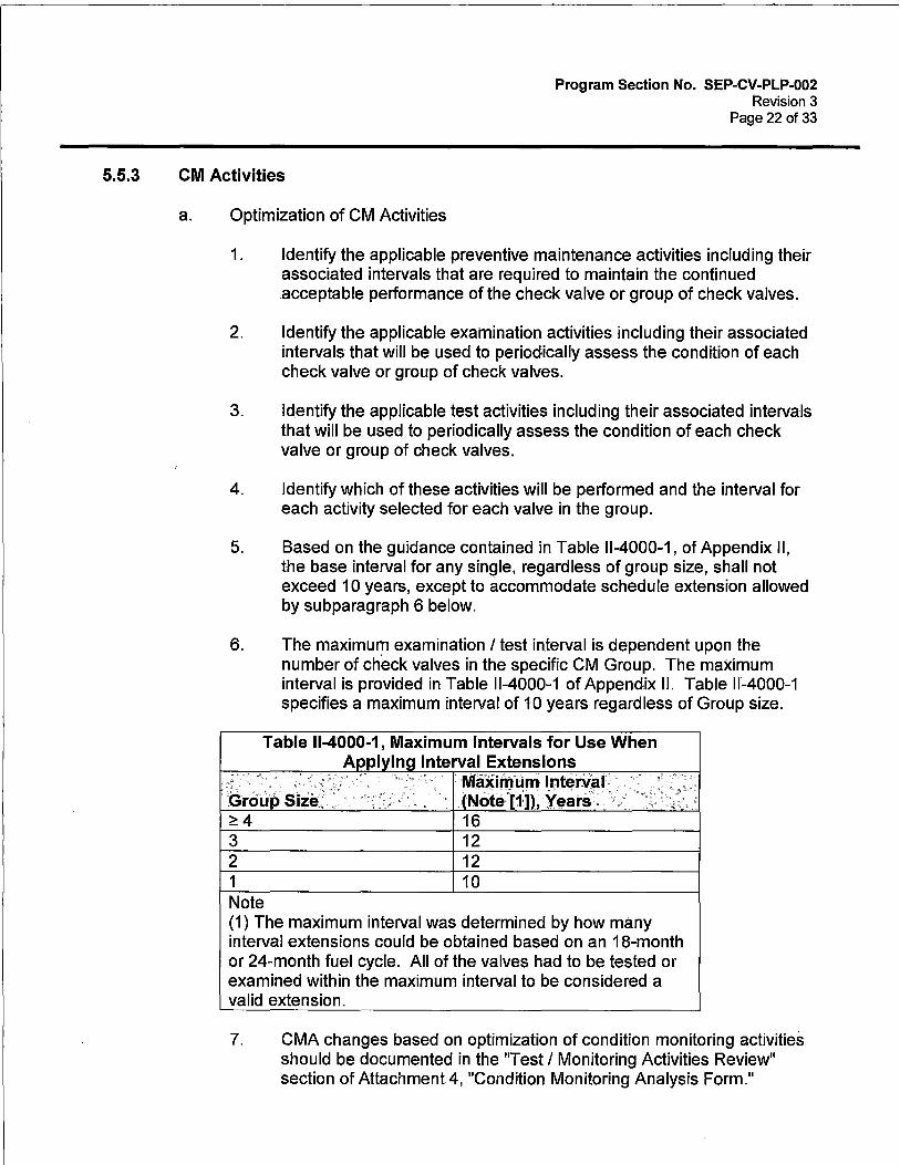
5.5.3 CM Activities
Program Section No. SEP-CV-PLP-002 Revision 3
Page 22 of 33
a. Optimization of CM Activities
1. Identify the applicable preventive maintenance activities including their associated intervals that are required to maintain the continued acceptable performance of the check valve or group of check valves.
2. Identify the applicable examination activities including their associated intervals that will be used to periodically assess the condition of each check valve or group of check valves.
3. Identify the applicable test activities including their associated intervals that will be used to periodically assess the condition of each check valve or group of check valves.
4. Identify which of these activities will be performed and the interval for each activity selected for each valve in the group.
5. Based on the guidance contained in Table 11-4000-1, of Appendix II, the base interval for any single, regardless of group size, shall not exceed 10 years, except to accommodate schedule extension allowed by subparagraph 6 below.
6. The maximum examination I test interval is dependent upon the number of check valves in the specific CM Group. The maximum interval is provided in Table 11-4000-1 of Appendix II. Table 11-4000-1 specifies a maximum interval of 10 years regardless of Group size.
Table 11-4000-1, Maximum Intervals for Use When
. . .
Grou·p· Si:ie .. ~4
3 2 1 Note
Interval Extensions Maximum lnteriial Not~· 1:n, x~ats'. ··/.
16 12 12 10
(1) The maximum interval was determined by how many interval extensions could be obtained based on an 18-month or 24-month fuel cycle. All of the valves had to be tested or examined within the maximum interval to be considered a valid extension.
7. CMA changes based on optimization of condition monitoring activities should be documented in the "Test I Monitoring Activities Review" section of Attachment 4, "Condition Monitoring Analysis Form."

Program Section No. SEP-CV-PLP-002 Revision 3
Page23 of 33
Complete or revise the test plan to document the optimized condition monitoring program activities and the associated intervals of each activity.
8. Perform these activities at their associated intervals.
b. Performance Improvement Activities
1 . Identify interim tests to assess the performance of the valve or the group of valves, such as non intrusives.
2. Identify interim examinations to evaluate potential degradation mechanisms.
3. Identify other types of analysis that will be performed to assess check valve condition.
4. Identify which of these activities will be performed, and their interval on each valve in the group.
5. The selected activities must be performed at sufficient intervals, over an interim period of the next five (5) years or two (2) refueling outages, whichever is less, to determine the cause of the failure or the maintenance pattern(s).
6. CMA changes based on performance improvement activities should be documented in the "Test I Monitoring Activities Review" section of Attachment 4, "Condition Monitoring Analysis Form." Complete or revise the test plan to document the performance improvement activities and their associated frequencies.
7. Perform these activities at their associated intervals until:
(a) Sufficient information is obtained to complete an adequate evaluation of the specific application; or
(b) Until the end of the interim period.
5.5.4 Condition Monitoring Analysis (CMA)
a. Each approved CMA will be signed and dated by the IST Program Engineer and CheckValve Program Engineer. Others may review and sign the CMA on an as needed basis. The CMA review and approval constitutes the CMA Review Panel.
b. When conducting and documenting the analysis, use the guidance that is provided on Attachment 4, "Condition Monitoring Analysis Form."

Program Section No. SEP-CV-PLP-002 Revision 3
Page 24 of 33
c. Use Attachment 5, "Folder Checklist," to assemble and organize the information needed to assist the Panel Reviewer's in assuring a complete and accurate picture of the group's performance.
5.5.5 Implementation and Review of CM Activities
a. Tests, examinations, and preventive maintenance activities must be scheduled and documented per the IST Program requirements of SEP-PLPIST-101, "lnservice Testing of Plant Valves."
b. Actions plans developed for condition monitoring activities must be in accordance with the CMA.
c. CMA changes based on test activities or corrective maintenance reviews should be documented in the "Test I Monitoring Activities Review" section of Attachment 4, "Condition Monitoring Analysis Form."
d. Extensions of CM intervals shall be supported and justified by the items described in the following statements to provide assurance that the valves in each group are capable of performing their intended functions over the selected interval.
1. Plant safety impacts described in the site's FSAR, technical specifications and design bases documents.
2. Industry generic experience and failure trends.
3. Plant specific experience and failure trends.
4. Plant specific inservice testing performance trends.
e. Review the results of these CM activities after their performance to determine if any changes to the CM analysis are warranted. If significant changes are needed, the CM analysis should be revised prior to the next CM activity interval.
1. Test Activities that are completed acceptably do not need further action or review.
2. Failure of a check valve test shall be reviewed for changes to CMA interval or group size.

5.5.6 CM Corrective Maintenance
Program Section No. SEP-CV-PLP-OQ2 Revision 3
Page 25 of 33
If corrective maintenance is performed on a check valve, the analysis used to formulate the basis of the Condition Monitoring activities for that valve and its associated valve group must be reviewed to determine if any changes are needed. If significant changes are needed, Attachment 4 for the valve group must be revised and the applicable requirements of this procedure repeated.
5.5.7 Required Records for CM
The condition monitoring program must be documented and include the following information, as a minimum:
a. · Check valves in the condition monitoring program and their associated group number must be identified in the IST Program.
b. The basis for the condition monitoring program, identified failure mechanisms and maintenance history patterns for each check valve, and condition monitoring activities and their associated intervals for each valve group. The Condition Monitoring Analysis Form, Attachment 4, is generated from the Check Valve Database. All data must be entered into this Microsoft Access database prior to generating the applicable CMA report.
c. The reason(s) and associated date for check valve inclusions or deletions are to be documented in the check valve database, as a minimum.
d. The Attachment 4, "Condition Monitoring Analysis Form," must be reviewed and revised if significant corrective maintenance is performed on a check valve, or group of valves·in the CM program.
e. When the CMA is completed (all approval signatures obtained), the hard copy is sent to Engineering Records per Entergy Procedure EN-AD-103, "Document Control and Records Management Programs." The Check Valve Engineer updates the check valve database to reflect the current approved CMA.
5.6 SUBSECTION ISTC, CHECK VALVE INSERVICE TESTING (IST) REQUIREMENTS
5.6.1 Type of Testing Required for Check Valve Categories
The types of testing required for the categories of check valves are described in OM Code 2004 Edition with Addenda through 2006, Subsections ISTC-3520, ISTC-3550 and ISTC 5221.
a. Valve Test Type Identification/Reference
Program Section No. SEP-CV-PLP-002 Revision 3
Page 26 of 33
The type of tests required for each check valve, and Relief Requests associated with Code testing exceptions, are contained in the lddeal Concepts Software Suite®.
5.6.2 Grouping Check Valves for Testing
a. Check Valves - Disassembly And Inspection
In accordance with OM Code, Subsection ISTC-5221 (c), grouping of check valves for the sample disassembly examination program shall be technically justified and shall consider, as a minimum .• valve manufacturer, design, service, size, materials of construction and orientation. Other items to consider when technically justifying check valve groupings include:
1. Maintenance and modification history
2. Potential flow instabilities
3. Required degree of disassembly
4. Need for tolerance or critical dimension checks
b. Check Valves - Nonintrusive Tests
In accordance with OM Code, Appendix II, groupings shall be technically justified and based on:
1. The intended purpose of the condition monitoring program, such as, improve performance or optimize testing, examination, and preventive maintenance activities;
2. Analysis of test results and maintenance history; and
3. Design characteristics, application and service conditions.
The grouping details of Section 5.6.2a should be considered, also.

5.6.3 Intervals for Testing Valves
Program Section No. SEP-CV-PLP-002 Revision 3
Page 27 of 33
The frequency required for performing each test type is identified in OM Code, Subsections ISTC-3510 for check valves exercised solely by the Subsection ISTC requirements. For check valves with leakage requirements, Subsection ISTC-3600 establishes the required test frequencies. For check valves subject to the Appendix II requirements, the maximum frequency is provided by Table 11-4000-1.
Unless otherwise specified, each check valve test surveillance requirement (SR) shall be performed within the specified time interval in accordance with the ASME OM Code or as allowed by Relief Request RR 5-2 which incorporates the requirements of ASME OM code case OMN-20 "IST Frequencies for Pumps and Valves"
Test frequencies for valve tests are identified in the lddeal Concepts Software Suite®.
a. Quarterly Testing Intervals
Ensuring valves can perform their open or close safety function is generally done on a quarterly basis (ie, every 92 days).
b. 18 Month/2 Year Testing Intervals
Valves that have close safety functions where seat leakage is limited and not based on Appendix J shall be tested at least once every 2 years.
c. Appendix J Testing - Valves With Containment Isolation Function Only
Valves whose only safety function is to isolate containment are tested on an interval as specified in 10 CFR 50, Appendix J, which is implemented in accordance with EN-DC-33'jl-, "Primary Containment Leakage Rate Testing (Appendix J)."
d. Cold Shutdown Testing Intervals
1. Valve exercising during cold shutdowns shall commence within 48 hours of achieving cold shutdown, and continue until all testing is complete or the plant is ready to return to power.
(a) For extended outages, testing need not be commenced in 48 hours provided all valves required to be tested during cold shutdown will be tested prior to plant startup.
(b) It is not required to keep the plant in cold shutdown (Technical Specification Mode 5) in order to complete cold shutdown testing. If cold shutdown testing is not completed,
Program Section No. SEP-CV-PLP-002 Revision 3
Page 28 of 33
then a justification shall be written documenting why the testing was not completed, per Palisades Administrative Procedure 9.20, "Technical Specification Surveillance and Special Test Program."
2. Cold Shutdown Justifications are contained in the lddeal Concepts Software Suite®. An index of these justifications is provided in Attachment 1, "Cold Shutdown Justification Index."
e. Refueling Outage Testing Intervals
1. All valve testing required to be performed during a refueling outage shall be completed prior to returning the plant to operation.
2. Refueling Outage. Justifications are contained in the lddeal Concepts Software Suite®. An index of these justifications is provided in Attachment 2, "Refueling Outage Justification Index."
f. Changes to Testing Intervals
It is the responsibility of the IST Coordinator to notify the Technical Specification Surveillance Procedure Program Administrator (TSSPA) of any change in the testing frequency for a particular piece of equipment. This change shall be documented in the test record.
g. Testing Interval Identification/Reference
Check Valve testing intervals are contained in the lddeal Concepts Software Suite®.
5.6.4 Scheduling Valve lnservice Tests
a. Technical Specification Surveillance Procedures
Most valve inservice tests are documented in Technical Specification Surveillance Procedures. These procedures are written to be conducted during specific plant mode(s) and are scheduled to be conducted in accordance with Palisades Administrative Procedure 9.20, "Technical Specification Surveillance and Special Test Program."
b. Departmental Procedures
Other valve inservice tests are documented in operating procedures such as General Operating Procedures (GOPs) and department procedures such as Chemistry (CH) procedures. These procedures are scheduled in accordance with the Palisades Work Control Process, 13 Week Schedule Program Planning and Scheduling Guidelines 2.0.

c. Periodic and Predetermined Activities
Program Section No. SEP-CV-PLP-002 Revision 3
Page29of 33
Several valve inservice tests are a part of the Periodic and Predetermined Activity Control (PPAC) program. PPACs are a way of implementing and controlling repetitive plant activities. PPACS are scheduled in accordance with Entergy Procedure EN-DC-324, "Preventive Maintenance Program."
d. Work Orders
Valve inservice testing may also be accomplished with Work Orders. Work Orders are scheduled in accordance with Entergy Procedure EN-WM-100," Work Request (WR) Generation, Screening and Classification," and Entergy Procedure EN-WM-105, "Planning."
e. Operations Logs
Various operational occurrences may verify that a valve is performing its safety function. These operational occurrences may be used as inservice tests if they are performed within required frequencies and when acceptable results are documented in accordance with OM Code, Paragraph ISTC-3550.
5.6.5 Criteria for Accepting Test Results
Acceptance criteria for check valve testing is contained in OM Code, Subsections ISTC-3530, ISTC-3550, ISTC-3620, ISTC-3630, ISTC-5221, ISTC-5222 and Appendix II.
a. Open and Close Tests - Check Valves
Verification of obturator movement of check valves shall be in accordance with OM Code, Paragraph ISTC-5221 or Appendix II. Refer to that section of the Code when determining acceptance criteria for verifying open or close safety functions of check valves. In general, obturator movement may be verified by:
1. Observing a direct indicator such as a position-indicating device.
2. Other indicator(s) such as changes in system pressure, flow rate, level, temperature, seat leakage testing, observation of pumps for reverse rotation, or other positive means.
3. Other positive means includes nonintrusive testing (NIT) techniques. Permanent Maintenance Procedure MSl-1-14, "Nonintrusive Diagnostic Check Valve Test Procedure," and Permanent Maintenance Procedure MSl-1-16, "Nonintrusive Diagnostic Valve Test Procedure
Program Section No. SEP-CV-PLP-002 Revision 3
Page 30 of 33
(Using Viper/UDS Platform)," are used to implement and analyze nonintrusive testing.
4. Disassembly and inspection.
b. Check Valve Non-intrusive Testing Reference Values
Valve disc movement tests (open and closed) do not require the use of reference values. However, acceptance criteria shall be established. Consequently, when using NIT to fulfill Code check valve testing, a baseline test demonstrating disc movement should be conducted to establish acceptance criteria. The baseline test shall be performed when the valve is known to be operating acceptably. Future test results shall be compared to the baseline test to evaluate check valve performance. ·
c. Leak Rate Tests
1. Acceptance criteria for Leak Rate tests for containment isolation valves shall be in accordance with 10 CFR 50, Appendix J. EN-DC-334, "Primary Containment Leakage Rate Testing (Appendix J)," provides the acceptance criteria that shall be satisfied for containment isolation valves.
2. For valves with safety functions (in addition to), or other than, containment isolation, acceptance criteria shall (also) be in accordance with OM Code, Paragraph ISTC-3630 for check valve.
d. Acceptance Criteria Identification/Reference
The acceptance criterion for each valve test is maintained in the document used to perform the test (ie, the implementing procedures).
5.6.6 Acceptance Criteria Outside of Code Allowed
a. If acceptance criteria used are outside Code allowed acceptance criteria, then a Relief Request shall be submitted for approval to the NRC in accordance with SEP~PLP-IST-101, "lnservice Testing of Plant Valves." NUREG-1482, "Guidelines for lnservice Testing at Nuclear Power Plants," Section 2.5, "Relief Requests and Proposed Alternatives" and Nuclear Energy Institute (NEI) White Paper entitled, "Standard Format for Requests from Commercial Reactor Licensees Pursuant to 10 CFR 50.55a, Revision 1," dated June 7, 2004 (ADAMS Accession No. ML070100400).
b. Relief Requests are contained in the lddeal Concepts Software Suite®. An index of the Relief Requests is provided in Attachment 3, "Relief Request Justification Index."
5.6.7 Valve Failure and Corrective Action
a. Processing Test Discrepancies
Program Section No. SEP-CV-PLP-002 Revision 3
Page 31 of 33
If a check valve fails to meet acceptance criteria during nonintrusive testing or disassembly and inspection the following actions shall be taken:
1. An Condition Report (CR) shall be initiated in accordance with Entergy Procedure EN-Ll-102, "Corrective Action Process."
2. Operability shall be determined in accordance with Entergy Procedure EN-OP-104, "Operability Determinations."
b. Check valve corrective actions are stated in OM Code, Paragraph ISTC-3630(f) and ISTC-5224 and as follows:
1. Category AC Check Valve - Seat Leakage Testing
Valves or valve combinations with leakage rates in excess of those specified in the appropriate test procedure shall be declared inoperable and either repaired or replaced.
A successful retest shall be performed prior to declaring the valve operable.
2. Category C Check Valves - Obturator Movement
If a check valve fails to exhibit the required change of obturator position, it shall be declared inoperable. A retest showing acceptable performance shall be run following any required corrective action before the valve is returned to service.
Series valve pairs tested as a unit that fail to prevent reverse flow shall be declared inoperable, and both valves shall be either repaired or replaced.
3. Category C Check Valves - Sample Disassembly Examination
Check valves that are not capable of full-stroke movement or have failed or have unacceptably degraded internals, shall have the cause of failure analyzed and the condition correcte~.
Other check valves in the sample group that may be affected by this failure mechanism shall be examined or tested during the same outage (or surveillance period) to determine the condition of internal components and their ability to function.

Program Section No. SEP-CV-PLP-002 Revision 3
Page 32 of 33
If an evaluation,· in accordance with the Entergy Procedure EN-Ll-102, "Corrective Action Process," determines that there are valves outside of the sampling group that could be directly affected by the failure mechanism, affected check valves should be examined or tested, in accordance with approved corrective action recommendations.
4. Category C Check Valves - Nonintrusive Tests
5.7 TRENDING
When a test using nonintrusive testing techniques is inconclusive, or when the results indicate unacceptable functioning of the check valve, actions are determined by the licensee. Actions may include additional testing, or disassembly and inspection. Permanent Maintenance Procedure MSl-1-14, "Nonintrusive Diagnostic Check Valve Test Procedure," and MSl-1-16, "Nonintrusive Diagnostic Check Valve Test Procedure (Using Viper/UDS Platform)," provide additional guidance.
If the "sampling" indicates problems with repeatability of the test conditions, or other problems that might affect the testing of the other valves, the non intrusive techniques must be used for the other valves during the same outage to comply with the sampling criteria.
The IST Coordinator is responsible to record and trend test data in order to predict when check valve degradation will exceed limits. The goal of this trending is to identify when a valve's ability to perform its function is degrading, allowing performance of needed repairs during convenient times prior to the valve becoming inoperable. Trending is typically accomplished with the lddeal Concepts Software Suite®. ~
The IST Coordinator may issue a Program Heath Assessment rating the health of the IST Valve program, and summarizing Corrective Actions. This periodic summary should be available for review by auditors and Plant personnel.

.'
Program Section No. SEP-CV-PLP-002 Revision 3
Page 33 of 33
6.0 ATTACHMENTS AND RECORDS
6.1 ATTACHMENTS
6.1.1 Attachment 1, "Cold Shutdown Justification Index"
6.1.2 Attachment 2, "Refueling Outage Justification Index"
6.1.3 Attachment 3, "Relief ReqLJest Justification Index"
6.1.4 Attachment 4, "Condition Monitoring Analysis Form"
6.1.5 Attachment 5, "Folder Checklist"
6.1.6 Attachment 6, "Appendix II Program Flow Chart"
6.2 RECORDS
Valve records shall be maintained as lifetime plant records. These records should be processed in accordance with EN-AD-103, "Document Control and Records Management Programs."
In accordance with the OM Code, Paragraph 9000, "Records and Reports," valve records shall consist of the following documents, as applicable:
a. Valve Records
b. Test Plans
c. Record of Tests
d. Record of Corrective Action
Records required by the lnservice Testing (IST) Program Code may be summarized in the lddeal Concepts Software Suite®., but are placed in the permanent record through other programs, such as, the Technical Specification Surveillance Program, Design Drawing Control (Color-Coded P&IDs), FSAR control, etc.
7.0 SPECIAL REVIEWS
None
CSJ-17:
Program Section No. SEP-CV-PLP-002 ATTACHMENT 1
Revision 3 Page 1of1
COLD SHUTDOWN JUSTIFICATION INDEX
Cold Shutdown Exercise Testing of CCS Check Valve • CK-CC910

Program Section No. SEP-CV-PLP-002 ATTACHMENT 2
Revision 3 Page 1of1
REFUELING OUTAGE JUSTIFICATION INDEX
ROJ-01 Refueling Outage Testing of HPSI Hot Leg Injection Check Valve • CK-ES3410
ROJ-02 Refueling Outage Testing of High Pressure Safety Injection Check Valves • CK-ES3104 • CK-ES3119 • CK-ES3134 • CK-ES3149
ROJ-03 Refueling Outage Testing of High Pressure Safety Injection Check Valves • CK-ES3250 • CK-ES3251 • CK-ES3252 • CK-ES3253
ROJ-04 Refueling Outage Testing of Hot Leg Injection Check Valves • CK-ES3408 • CK-ES3409
ROJ-05 Refueling Outage Testing of Service Water Pump Discharge Check Valves • CK-SW401 • CK-SW402 • CK-SW403
ROJ-06 Refueling Outage Testing of Safety Injection Tank Check Valves • CK-ES3102 • CK-ES3117 • CK-ES3132 • CK-ES3147
ROJ-07 Refueling Outage Testing of PCS Loop Check Valves • CK-ES3101 • CK-ES3116 • CK-ES3131 • CK-ES3146
ROJ-08 Refueling Outage Testing of Containment Spray Pump Discharge Check Valves • CK-ES3208 • CK-ES3220 • CK-ES3230

RR No
5-2
Program Section No. SEP-CV-PLP-002 ATTACHMENT 3
Revision 3 Page 1of1
RELIEF REQUEST JUSTIFICATION INDEX
Description
Use of OMN-20 IST Frequencies for Pumps and Valves

Program Section No. SEP-CV-PLP-002 ATTACHMENT 4
Revision 3 Page 1 of?
CONDITION MONITORING ANALYSIS FORM
Grouping Information
CM Grouping: Revision: Revision Date: Equip ID(s) in Group:
Activity Type:
Analysis Reason:
References:
D D D
D D D D D D
No Title I Description (examples given)
Performance Improvement Optimization of Condition Monitoring Other:
-----
----------------Establish Initial Grouping and Analysis Revision due to Corrective Maintenance Change in Test Strategy Change in Grouping Scope or Basis Removal from Condition Monitoring Program Other:
--------------~
Remarks
1. SEP-CV-PLP-001 "Check Valve Program" 2. SEP-PLP-IST-101 "lnservice Testing of Plant Valves" 3. IST Pump and Valve Database 4. Etc
Grouping Bases
Evaluation of Group:
DESIGN - Identify pertinent valve design characteristics, features, and manufacturing data. Per Nureg 1482 Revision 2, "The check valves in this group are all of the same design (eg, type, size, manufacturer, model, and materials of construction)." Any differences should be identified and technically justified.
• Consider tolerances and critical dimension checks required for the group.
• Consider degree of disassembly required for check valves in the group.
• This information can be found in vendor catalogues, vendor drawings and engineering documents such as FESs and SCs.
Program Section No. SEP-CV~PLP-002 ATTACHMENT 4
Revision 3 Page2 of?
CONDITION MONITORING ANALYSIS FORM
APPLICATION - Describe value application in the system I train (orientation, location,
•
•
•
•
SERVICE-
and turbulent sources). The check valves in this group all have the same application (eg, orientation, flow stabilities, upstream turbulence sources, and system function).
This information can be found by looking at stress isometric drawings (SISO) and Piping and Instrument Diagrams (P&IDs). Useful information can also be found in Phase Ill of the Palisades Check Valve Final Report supplied by ABB Combustion Engineering.
In situ orientation (horizontal, vertical, or skewed) .
Flow characteristics .
Upstream turbulence sources? (Pumps I CVs within10 pipe diameters, Tees I Reducers I Elbows within 5 pipe diameters.
Identify any service conditions (dirt, erosion, corrosion, duty cycles and duration of service, and any other pertinent aging effects) that could effect valve operation.
The check valves in this group all have the same service conditions (eg, usage, environment and history).
• This information can be found in Maintenance Rule Availability information, System health reports and by consulting system engineers. Much of this analysis is dependent on knowledge gained by experience, and is therefore often best gained through individuals rather than documents and databases. Some useful information can also be found in Phases I, Ill and IV of the Palisades Check Valve Final Report supplied by ABB Combustion Engineering.
• Usage: describe service conditions and indicate approximate number of weeks with flow (continuous operation, event driven I cyclic operations, accident or infrequent operation).
• Environment (harsh, high temperature, radiological).
• Corrosive, basic or chemical fluid?
• Is system free of dirt, corrosion, and other contaminants?
• Work order and modification related work order history and corrective action history commonalties.

Program Section No. SEP-CV-PLP-002 ATTACHMENT 4
Revision 3 Page 3 of7
CONDITION MONITORING ANALYSIS FORM
MAINTENANCE RULE (MR) - Identify applicable support function(s).
PROBABILISTIC SAFETY ASSESSMENT (PSA) - Identify ranking I significance used in PSA model.
PM PROGRAM - EPRI PM Template classification. Additional Bases:
P_ROG~AM - Document any other program basis information or additional justification for the group.
NOTES: List any applicable component information such as AOV or MOV Engineering Anal ses.
REFERENCES - List any additional references specific to this valve grouping.
Initial Program Assessment
Test I Exam I PM Title Failure Cause Monitored Bll Freq Performance Activitv Monitored Assessment
Identify all known current activities (tests, examinations, system monitoring activities, and preventive maintenance tasks) that are being performed and that can be used to determine valve condition or capability. These activities should then be assessed for their effectiveness.
• There are many databases on the network where this information can be obtained.
• Failure Cause Monitored are those failure causes established by NIC.
• Monitored By describe if they are directly or indirectly measured or observed and a brief description of what or how the monitoring is accomplished?
• Performance Assessment Rate the activity's effectiveness and why?

Performance Issues
Program Section No. SEP-CV-PLP-002 ATTACHMENT 4
Revision 3 Page4 of 7
CONDITION MONITORING ANALYSIS FORM
Work Order History Review: Identify any problems and summarize the results for the group.
• The Microsoft Access check valve database is used to find this information. The database accesses Palisades' work order history database. The summary of each work order can then be read and evaluated as to their applicability towards CM activities.
• Modification related work orders (WOs) should be listed by EquiplD, WO#, and Date Completed.
• Maintenance related WOs should be listed by EquiplD, WO#, and Date Completed.
Corrective Action Record Review: Identify applicable Action Requests (ARs), Condition Evaluations (CEs) and Corrective Actions (CA) and summarize the results for the group.
• The Microsoft Access check valve database can be used to find this information. The database accesses a Palisades' database that contains archived Corrective Actions (CA). The summaries of each corrective action can then be read and evaluated as to their applicability towards CM activities.
• AR/CE/CA documents should be listed by their Initiated Dates.
Identified Maintenance Failure Patterns: Review previous tests, examinations, maintenance activities, and corrective actions to identify any common failure or maintenance patterns. Evaluate these patterns for their significance and failure mechanisms.
Industry Operating Experience Review: Use industry data sources and identify pertinent valve performance issues, any common failure and maintenance patterns, or other pertinent information relating to valve performance.
• List any other industry data sources or documents reviewed as part of this assessment (Operating Experience, IE Notices and Bulletins, Generic Letters, Vendor input, NIC Performance Templates and Failure Database, INPO Databases like ICES). Provide c;t short summary of how each was dispositioned for this analysis.
• This information can be found by using the INPO and NRC web sites.

Program Section No. SEP-CV-PLP-002 ATTACHMENT 4
Revision 3 Page 5 of?
CONDITION MONITORING ANALYSIS FORM
INPO's web site contains the INPO Consolidated Event System databases (ICES). This database is to be used to search for failure reports based on selected valve criteria. The INPO web site also contains the Nuclear Network. This database allows searches of numerous documents pertaining to equipment reliability issues. NRC's web site contains Part 21, LER, NUREGs, IENs, IE Bulletins, Generic Letters, all of which are searchable.
• This information can also be found in the Nuclear Industry Check Valve Group (NIC) failure data database.
Identified Industry Failure Patterns:
• Use the NIC maintenance I failure templates, if available.
• Operating experience is a broad scope and can involve many hours of searching through the various databases. The OE Coordinator and MR Rule Engineer can be used as a resource in determining appropriate search criteria.
Failure Modes and Causes
For each of the following Significant Failure Modes, identify the possible failure cause(s) to this grouping of check valves, as applicable.
Failure to Open Restricted Motion Broken or Detached Parts
Failure to Close Gross Internal Leakage
• These failure modes are considered broad enough to capture all significant failures.
• Identify if the failure mode is possible, or valid, and then rate it as likely or unlike to occur in the valve grouping. Specify the reasons why for validity and rating.
Failure Modes Evaluation: Provide both PLANT and INDUSTRY information and evaluation of failure modes and causes to support selection of appropriate activities to be performed.

Program Section No. SEP-CV-PLP-002 ATTACHMENT 4
Revision 3 Page 6 of?
CONDITION MONITORING ANALYSIS FORM
Optimized Performance Strategy
These activities must be sufficient to detect or mitigate the identified patterns or mechanisms.
Test I Exam I PM Activitv Frea Cause Monitored How Monitored Exoected Results
• List only those activities (Test I Exam I PM) that will be used to monitor the group and provide a short description of the activity.
• Specify the Frequency at which the activity will be performed.
• Identify failure causes I modes which will be monitored and the capability of this activity to detect it.
• Explain how the activity is monitored or accomplished; if it is directly or indirectly observed or measured. The expected results should state the effectiveness of the activity to determine the condition being monitored.
• Expected ResuJts should include the effectiveness of the activity.
Proposed Monitoring Activities:
The condition monitoring strategy developed for this grouping must address all the possible failure modes. Provide additional information and description of proposed activities here.
Implementation Plan:
The implementation plan should provide mutual agreement as to how to change I revise the existing program plan to achieve the optimized plan (how to get there).
Test I Monitoring Activities Review:
This section should capture and document the reviews done for this grouping. Reviews include corrective maintenance, operating experience, and periodic assessments.

Program Section No. SEP-CV-PLP-002 ATTACHMENT 4
Revision 3 Page 7 of7
CONDITION MONITORING ANALYSIS FORM
Panel Review
Review Remarks I Comments: Include any pertinent comments from the review and approval process.
Reviews and Approvals: (signature and date) Check Valve Program Engineer (*):
IST Program Engineer (*):
(*) Indicates the minimum approvals required for IST grouping evaluations.
Others (as needed)
System Engineer:
Operations Dept Rep:
PSA Group R~p:

1
2
3
4
5
6
7
8
9
10
11
12
Program Section No. SEP-CV-PLP-002 ATTACHMENT 5
Revision 3 Page 1of1
FOLDER CHECKLIST
The Component Engineer and CMA Review Panel intend this information file for ready access, on-hand, and information-only copy type items. All original documents are on file per the normal document retention process.
CHECK LIST FOR GROUPING NO:
Check Valve Assessment I CMA (printed from database)
IST REPORTS (IF APPLICABLE FROM PV-PLUS)
• Component Information and Basis
• Code Deviations (ROJ/RR)
Vendor Manual Pages I Valve Drawing(s)
Isometric and P&ID drawings
Piping Class ~ummary Sheet
MAINTENANCE AND MODIFICATION RELATED WO HISTORY SUMMARY
• Retrack printout of equipment number(s) (search using old and new EquiplD-eg, '*CK*ES3166*' or '*CK*3166*' with System 'ES*')
• Copy of WO History Report with p~rtinent pages from microfilming that support technical justification of basis (eg, inspection form with dimensional data, modification design information, etc.)
CORRECTIVE ACTION (CA) HISTORY I
• Corrective Action Listing
• CA Docs Associated with Equipment
• Copies of pertinent ARs/ CEs/ CAs that support technical justification of basis
OPERATING/ INDUSTRY EXPERIENCE
• Valve failure information from ICES or NIC Failure database • ICES (SOER, SER, OE)
• Valve failure and temolate information from NIC • NRC documents (IE Notices, PART 21, IE Bulletins, Generic Letters)
• Vendor technical bulletins, memos, etc .
Maintenance Rule (MR) Function(s) per EGAD-EP-10 Attachment 2
PSA Risk Ranking Results
MISCELLANEOUS
• Other misc. information relating to the valve(s) (eg, control valve engineering analysis in-line with CK).
• PPAC information
• Other:
VALVE SPECIFIC INFORMATION I DATA
• CK Basis I Design Report Pages
• Q-List Equipment Listing (screen prints from AMMS)
• Valve Survey Sheet
../THOSE THAT ARE INCLUDED

Program Section No. SEP-CV-PLP-002 ATTACHMENT 6
Revision 3 Page 1of1
APPENDIX II PROGRAM FLOW CHART
IDENTIFY CM ACTIVITIES FOR INTERIM PERIOD
PERFORM CM ACTIVITIES AND
CHECK FOR CORRECTIVE MAINT
DOCUMENT CM PERFORMANCE IMPROVEMENT
ACTIVITIES
No
No
BASIS OF GROUPINGS
ANALYSIS OF TEST AND MAINTENANCE
ACTIVITIES
Yes
No
OPTIMIZATION OF ACTIVITIES
IDENTIFY CM ACTIVITIES AND
INTERVALS
PERFORM CM ACTIVITIES AND
CHECK FOR CORRECTIVE MAINT
DOCUMENT CM PROGRAM
Yes
Yes

Palisades Nuclear Plant lnservice Testing (IST) Program Plan
Fifth Ten-Vear Interval
Section 4.0
SEP-PLP-IST-102
lnservice Testing of Selected Safety Related Pumps
Page 194
(50 pages follow)

Program Section No. SEP-PLP~IST-102 Revision 2
Pagei
INSERVICE TESTING OF SELECTED SAFETY-RE;LATED PUMPS
ENGINEERING NUCLEAR ENGINEERING PROGRAMS
APPLICABLE SITES
All Sites: D
Specific Sites: ANO D GGNS D IPEC D JAF D PLP [8J PNPS D RBS D VY D W3 D HQN D
Current Revision
2
1
Safety Related: Yes No
Program Section Revision Summary Description of Change
Revised the Program Section to reflect the 10 year code update from The ASME OM Code 2001 Edition through 2003 Addenda to the 2004 Edition through the 2006 Addenda. Added references 3.28 and 3.29 for Program Section SEP-ISl-PLP-003, "Palisades lnservice Inspection Master Plan Fourth Interval, ASME Section XI, Division 1" and Program Section CEP-RR-001, "ASME Section XI Repair/Replacement Program" per WT-PLP-2012-00427 CA-44.
Added section 5.4.5 under the Corrective Action section of the Program Section to reference the requirements of ISTB-6300 as it relates to the requirement to rerun the test if instrument inaccuracies are identified which resulted in the test to be outside of its acceptance criteria. This section was added per CR-PLP-2014-04881 CA-6.
Revised the approval section of Attachment 5 to require the Preparer of the IST Pump Reference Value(s)/Range(s) Change Form to be a qualified IST Engineer instead of the approver. A non IST qualified individual should not be preparing the change form. This requires the preparer to be qualified and allows approval by a supervisor or another knowledgeable person.
Added reference 3.30 for Program Section SEP-ISl-PLP-002, "ASME Code Boundar.ies for ASME Section XI lnservice Inspection Program" per WT-PLP-2012-00427 CA-37.
0 Transitioned from Palisades Engineering Manual EM-09-04, Revision 24, "lnservice Testing of Selected Safety Related Pumps". The transition also performed the following:
Incorporated the following Document Revision Notices:

PCR01088174 PCR01089833 PCR01090331 DRN-11-01125
Program Section No. SEP-PLP-IST-102 Revision 2
Page ii
Added Attachment 5, "lnservice Testing Program Pump Reference Value/Ranges Change Form"
Revised Section 2.0 to more clearly define the scope of the procedure
Updated references 3.3, 3.4, 3. 7 and 3.9
Added references 3.25 and 3.26
Revised section 4.0 to update the definitions to align with the ASME OM Code 2001 with Addenda through 2003, Operation and Maintenance of Nuclear Power Plants, Subsections ISTA and ISTB
Revised section 5.4 to include additional corrective action requirements specified by the ASME OM Code 2001 with Addenda through 2003, Operation and Maintenance of Nuclear Power Plants, Subsections ISTA and ISTB.
Revised Attachment 4 to include the latest reference values for the pumps.
Revised various procedure sections for clarification and editorial changes

Program Section No. SEP-PLP-IST-·102 Revision 2
Page iii REVIEW AND CONCURRENCE SHEET
Program Section Title: INSERVICE TESTING OF SELECTED SAFETY RELATED PUMPS
Prepared By: G Katt hrA )\tdot Date: 3-22-16
Checked By: R White ~AfJ/~ Date: 3-22-16
Reviewed By: N/A Date: (Optional)
ANll: N/A Date:
(Reviewed By or NIA)
Concurred: JMJerz ~lo Date: 3-22-16
Responsible Supervisor

SECTION Main Body Main Body Main Body Main Body Main Body Main Body Main Body Main Body Main Body Main Body Main Body Main Body Main Body Main Body Main Body Attachment 1 Attachment 2 Attachment 3 Attachment 4 Attachment 5 Attachment 6
Program Section No. SEP-PLP-IST-102 Revision 2
Page iv REVISION STATUS SHEET
PAGE NO. 1 2 3 4 5 6 7 8 9 10 11 12 13 14 15 All All All All All All
REVISION 2 2 2 2 2 2 2 2 2 2 2 2 2 2 2 2 2 2 2 2 2

Table of Contents
Program Section No. SEP-PLP-IST-102 Revision 2
Pagev
1.0 PURPOSE ...................................................................................................................... 1
2.0 SCOPE ........................................................................................................................... 1
3.0 REFERENCES ............................................................................................................... 2
4.0 DEFINITIONS AND RESPONSIBILITIES ...................................................................... 5
4.1 DEFINITIONS ................................................................................................. 5
4.2 RESPONSIBILITIES ...................................................................................... 7
5.0 PROCEDURES ........................................................................................... .-.................. 7
5.1 FREQUENCY AND SCHEDULING OF TESTS ............................................. 7
5.2 PUMP REFERENCE VALUES ...................................................................... 9
5.3 DATA EVALUATION ................................................................................... 11
5.4 CORRECTIVE ACTION: ............................................................................... 12
5.5 TRENDING ................................................................................................... 13
6.0 RECORDS AND ATTACHMENTS ............................................................................... 14
6.1 RECORDS ................................................................................................... 14
6.2 ATTACHMENTS ......................................................... , ................................ 15
ATTACHMENTS
Attachment 1, "Pump Testing System Index" Attachment 2, "Allowable Ranges of Test Quantities" Attachment 3, "Pump Testing Plan" Attachment 4, "Group A and B Pump Test Hydraulic Circuits" Attachment 5, "IST Pump Reference Value(s)/Range(s) Change Form" Attachment 6, "Pump Summary Listing"

1.0 PURPOSE
Program Section No. SEP-PLP-IST-102 Revision 2
Page 1 of 15
1.1 This procedure provides general requirements for the performance and administration of the lnservice Testing Program for selected pumps.
1.2 This procedure establishes the requirements for the implementing procedures for inservice testing and evaluation of selected pumps.
1.3 This document contains one or more steps or sections that implement a Nuclear Regulatory Commission requirement and/or commitment to manage the effects of aging on systems, structures, and components within the scope of license renewal .as described in Palisades Administrative Procedure 3.26, "Implementation of Palisades Renewed License Requirements," and Site Engineering Program SEPRLP-PLP-001, "Renewed License Program." Renewed License requirements are designated "[RLR]," and Renewed License commitments are designated "[RLC]."
FSAR Section 1.9.1.6 and renewed license tracking document ,.., LR-LAR-2009-00244-53 provide the description of the Renewed License Aging Management Program that credits this procedure for implementation of the aging management program requirements. [RLR]
2.0 SCOPE
2.1 This document outlines Fifth Ten-Year Interval Program Plan for In-service Testing (IST) of Pumps at the Palisades (PLP) Nuclear Power Plant. This Program Plan was prepared in accordance with the rules of the ASME Code for Operation and Maintenance of Nuclear Power Plants, ASME OM Code-2004, through the ASME OMb Code-2006 Addenda (OM-2004 through OMb-2006).
2.2 The Palisades Plant lnservice Pump Testing Program Plan will be in effect through the Fifth 120-month interval (2016 through 2026) and will be updated in accordance with 1 OCFR50.55a(f).
2.3 The NRC has indicated in Generic Letter 89-04 that the intent of 10 CFR 50. Appendix A, GDC-1, and Appendix B, Criteria XI, is that all safety-related pumps and valves should be tested to demonstrate they will perform satisfactorily in service. 10 CFR 50.55a delineates testing requirements only for ASME Code Class 1, 2 and 3 components required for reactor shutdown or accident mitigation. In addition to those ASME Code Class components subject to testing under 10 CFR 50.55a, this Procedure may include safety related non-ASME Code Class (augmented) components which perform specific safety related functions as defined in ASME OM scope statements.
2.4 The requirements of this procedure apply to certain centrifugal and positive displacement pumps that have an emergency power source.

2.5 The following are excluded from this procedure:
Program Section No. SEP-PLP-IST-102 Revision 2
Page 2of15
(a) Drivers, except where the pump and driver form an integral unit and the pump bearings are in the driver;
(b) Pumps that are supplied with emergency power solely for operating convenience; and
(c) Skid-mounted pumps that are tested as part of the major component and are justified by the Owner to be adequately tested.
2.6 Attachment 1 provides a complete listing of those pumps included in this program per the requirements of the ASME OM Code, Subsections ISTB-1100 through ISTB-1400.
2.7 Attachment 3 provides the Pump Testing Plan.
3.0 REFERENCES
3.1 ASME OM Code 2004 with Addenda through 2006, Operation and Maintenance of Nuclear Power Plants, Subsections ISTA and ISTB ·
3.2 Generic Letter 89-04, "Guidance on Developing Acceptable lnservice Testing Programs"
3.3 NUREG-1482, Rev. 2, "Guidelines for lnservice Testing at Nuclear Power Plants"
3.4 Code of Federal Regulations, Title 10, Part 50 (10 CFR 50)
3.5 Technical Specifications ADMIN 5.5.7
3.6 Technical Specifications SR 3.0.2, SR 3.5.2.4, SR 3.6.6.5, SR 3.7.5.2
3.7 FSAR 6.9.2.1, "Pump Testing Program"
3.8 Entergy Quality Assurance Program Manual
3.9 Entergy Procedure EN-DC-310, "Plant Predictive Maintenance Program"
3.10 Palisades Administrative Procedure 9.20, "Technical Specification Surveillance and Special Test Program"
3.11 Palisades Administrative Procedure 10.41, "Site Procedure and Policy Processes"
3.12 Palisades Administrative Procedure 10.51, "Writer's Guideline for Site Procedures"
3.13 Entergy Procedure EN-AD-102, "Procedure Adherence and Level of Use"
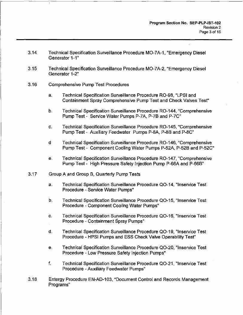
Program Section No. SEP-PLP-IST-102 Revision 2
Page 3of15
3.14 Technical Specification Surveillance Procedure M0-7A-1, "Emergency Diesel Generator 1-1"
3.15 Technical Specification Surveillance Procedure M0-7 A-2, "Emergency Diesel Generator 1-2"
3.16 Comprehensive Pump Test Procedures
a. Technical Specification Surveillance Procedure R0-98, "LPSI and Containment Spray Comprehensive Pump Test and Check Valves Test"
b. Technical Specification Surveillance Procedure R0-144, "Comprehensive Pump Test- Service Water Pumps P-7A, P-78 and P-7C"
c. Technical Specification Surveillance Procedure R0-145, "Comprehensive Pump Test - Auxiliary Feedwater Pumps P-8A, P-88 and P-8C"
d Technical Specification Surveillance Procedure R0-146, "Comprehensive Pump Test - Component Cooling Water Pumps P-52A, P-528 and P-52C"
e. Technical Specification Surveillance Procedure R0-147, "Comprehensive Pump Test - High Pressure Safety Injection Pump P-66A and P-668"
3.17 Group A and Group 8, Quarterly Pump Tests
a. Technical Specification Surveillance Procedure Q0-14, "lnservice Test Procedure - Service Water Pumps"
b. Technical Specification Surveillance Procedure Q0-15, "lnservice Test Procedure - Component Cooling Water Pumps"
c. Technical Specification Surveillance Procedure Q0-16, "lnservice Test Procedure - Containment Spray Pumps"
d. Technical Specification Surveillance Procedure Q0-19, "lnservice Test Procedure - HPSI Pumps and ESS Check Valve Operability Test"
e. Technical Specification Surveillance Procedure Q0-20, "lnservice Test Procedure - Low Pressure Safety Injection Pumps"
f. Technical Specification Surveillance Procedure Q0-21, "lnservice Test Procedure -Auxiliary Feedwater Pumps"
3.18 Entergy Procedure EN-AD-103, "Document Control and Records Management Programs"

3.19
3.20
3.21
3.22
3.23
3.24
3.25
3.26.
3.27
3.28
3.29
3.30
Program Section No. SEP-PLP-IST-102 Revision 2
Page 4of15
Engineering Assistance Request EAR-99-0081, "CVCS Declassification"
Palisades Administrative Procedure 3.26, "Implementation of Palisades Renewed License Requirements"
Site Engineering Program SEP-RLP-PLP-001, "Renewed License Program - Aging Management Activities"
FSAR 1.9.1.6, "Closed Cycle Cooling Water Program"
LO-LAR-2009-00244-53, "Implement a Closed Cycle Cooling Water Program as described in FSAR Section 1.9.1.6"
Entergy Procedure EN-HU-102, "Human Performance Tools"
Entergy Procedure EN-DC-332, "lnservice Testing"
Entergy Program Section No. CEP-IST-4, "Standard on lnservice Testing"
Entergy Procedure EN-Ll-102, "Corrective Action Process"
Program Section SEP-ISl-PLP-003, "Palisades lnservice Inspection Master Plan Fifth Interval, ASME Section XI, Division 1"
Program Section CEP-RR-001, "ASME Section XI Repair/Replacement Program"
Program Section SEP-ISl-PLP-002, "ASME Code Boundaries for ASME Section XI lnservice Inspection Program"

4.0 DEFINITIONS AND RESPONSIBILITIES
4.1 DEFINITIONS
Program Section No. SEP-PLP-IST-102 Revision 2
Page 5of15
4.1.1 Alert Range - That range (Attachment 2) for a given pump parameter outside the normal operating range in which an increased testing frequency is specified.
4.1.2 Group A Pump -A pump that is operated continuously or routinely during normal operation, cold shutdown, or refueling operations.
4.1.3 Group B Pump - A pump that is in standby systems that are not operated routinely except for testing.
4.1.4 lnservice Test -A test to assess the operational readiness of a system, structure, or component after first electrical generation by nuclear heat.
4.1.5 Instrument Loop - Two or more instruments or components working together to provide a single output.
4.1.6 Instrument Loop Accuracy - The accuracy of an instrument loop based on the square root of the sum of the squares of the inaccuracies of each instrument or component in the loop when considered separately. Alternatively, the allowable inaccuracy of the instn,iment loop may be based on the output for a known input into the instrument loop.
4.1.7 Maintenance - The replacement of parts, adjustments, and similar actions that do not change the design (configuration and material) of an item.
4.1.8 Modification - The alteration in the design of a system, structure, or component.
4.1.9 Monitoring - The continuous or periodic observation or measurement to ascertain the performance or obtain characteristics of a system, structure, or component.
4.1.10 Owner: - An organization owning or operating a facility where items are installed or used.
4.1.11 Plant Operation - The conditions of startup, operation at power, hot standby, and reactor cooldown, as defined by plant technical specifications.
4.1.12 Preservice Test - A test performed after completion of construction activities related to the component and before first electrical generation by nuclear heat, or in an operating plant, before the component is initially placed in serviGe.
4.1.13 Preservice Test Period - The period of time following completion of construction activities related to the component and before first electrical generation by nuclear heat, in which component and system testing takes place, or in an operating plant prior to the component being initially placed in service.

Program Section No. SEP-PLP-IST-102 Revision 2
Page 6of15
4.1.14 Reference Point - A point of operation at which reference values are established and inservice test parameters are measured for comparison with applicable acceptance criteria.
4.1.15 Reference Values - One or more values of parameters as measured or determined when the equipment is known to be operating acceptably. Reference values provide baseline values for comparison in subsequent IST for detecting pump or valve degradation. Reference values are determined from the results of a baseline preoperational or inservice test. They shall be at points of operation which are readily duplicated during subsequent inservice testing, the results of which are compared to these reference values.
4.1.16 Relief Request - A written request to the NRC seeking relief from certain Code requirements when those requirements are impractical, cause unreasonable hardship without a compensating increase in safety or when a proposed alternative provides an acceptable level of quality and safety.
4.1.17 Repair - The process of restoring a degraded item to its original design requirements.
4.1.18 Required Action Range - That region (Attachment 2) outside the upper and lower limits of the alert range, as applicable, in which the pump is considered inoperable until the cause of the deviation has been determined and the condition corrected.
4.1.19 Routine Servicing - The performance of planned, preventive maintenance.
4.1.20 Skid-mounted Pumps and Valves - Pumps and valves integral to or that support operation of major components, even though these pumps and valves may not be located directly on the skid. In general, these pumps and valves are supplied by the manufacturer of the major component.
4.1.21 Substitute Examination or Test - An examination or test which replaces a Coderequired examination or test when the Code requirements are considered to be impractical.
4.1.22 System Resistance - The hydraulic resistance to flow.
4.1.23 Trending - A comparison of current data to previous data obtained under similar conditions for the same equipment.
4.1.24 Vertical Line Shaft Pump - A vertically suspended pump where the pump driver and pump element are connected by a line shaft within an enclosed column.

4.2 RESPONSIBILITIES
Program Section No. SEP~PLP-IST-102 Revision 2
Page 7of15
4.2.1 Procedure EN-DC-332, "lnservice Testing," identifies division of responsibilities at the Department level for each Entergy site.
4.2.2 IST Coordinator - That individual assigned to oversee performance of the pump testing program. The IST Coordinator performs the following: • Develops and implements the IST Program and Plan. • Reviews and records IST test results and informs applicable department head(s)
of recommended corrective actions or new IST value~. • Reviews inservice and pre-service test results and determines appropriate
reference values, when required. • Notifies appropriate plant departments of the need for special inservice testing. • Reviews surveillance procedures used to implement the IST Program with
respect to applicability and compliance with the IST Program. • Reviews plant modifications and other information provided by the Design
Engineering Manager with respect to activities that have a potential impact on the scope of the IST Program.
• Provides assistance to the Operations Manager in determining the post-work test requirements including the testing required for establishing revised IST values and limits.
• Ensures all tests and test parameter measurements are properly documented and in compliance with the requirements of the IST Program for Pumps and Valves.
• Provides a copy of the IST Program Plan, including subsequent revisions, to the Licensing Manager for submittal to the NRC as necessary.
4.2.3 Technical Specification Surveillance Program Administrator (TSSPA) - The individual responsible for the administration of the Technical Specification Surveillance Program.
4.2.4 System Engineer - Service manager for the system in question.
5.0 PROCEDURES
5.1 FREQUENCY AND SCHEDULING OF TESTS
5.1.1 lnservice tests shall be run on each Group A or B pump in the program nominally every 3 months during normal Plant operation. Additionally, each Group A or B pump shall be subject to a comprehensive' pump test on a biennial basis (every 2 years). Group B pumps that do not have the required fluid inventory (eg, pumps in dry sumps) shall only be subject to a biennial comprehensive pump test. This test frequency should be maintained during shutdown periods if this can be reasonably accomplished, although this is not mandatory. ASME OM Code, ISTB-3420 requires that pumps in systems declared inoperable or not required to be operable (eg, during Plant shutdown periods) need not be tested on the required frequency;

Program Section No. SEP-PLP-IST-102 Revision 2
Page 8 of 15
however, they shall be tested within 3 months prior to placing the system in an operable status. Pumps which can only be tested during Plant operation shall be tested within 1 week (7 days) of startup.
5.1.2 If a pump is operated more frequently than once per quarter or is operated for other reasons such as a special test, it need not be started or stopped specifically for the surveillance test. In order to take credit for these operations, however, the pump must be run at least once every 3 months at the reference conditions and all required test data must be recorded. The IST Coordinator must then evaluate and trend the data and complete a "Surveillance Not Done Justification" form (Admin 9.20 - Attachment 9). [RLR]
5.1.3 Unless otherwise specified, each inservice test surveillance requirement shall be performed within the specified time interval specified by the ASME OM Code or as allowed by Relief Request RR 5-2 which incorporates the requirements of ASME OM code case OMN-20 "IST Frequencies for Pumps and Valves".
5.1.4 If a pump is replaced or a repair is made which may have affected any of the pump reference values as determined by the IST Coordinator, a new reference value or set of reference values shall be determined or the previous value reconfirmed by an inservice test in accordance with ASME OM Code, Subsection ISTB-3310.
5.1.5 If pump parameters determined during a quarterly inservice test fall within the alert range, the test frequency shall be doubled. The IST Coordinator and TSSPA shall ensure inservice testing is performed at the increased test frequency until the cause of the deviation is determined and the condition corrected.
5.1.6 Each test procedure shall include the pump reference values and corresponding alert and required action ranges. These shall be presented in such a manner that the shift individual(s) responsible for conducting the test (ie, Shift Manager, Reactor Operator) is able to make a timely determination as to whether or not the data meets operability requirements.
5.1.7 All Technical Specification Surveillance Procedures associated with the Palisades pump inservice testing program shall be developed in accordance with Palisades Administrative Procedures 9.20, "Technical Specification Surveillance and Special Test Program," 10.51, "Writer's Guideline for Site Procedures," Palisades Administrative Procedure 10.41, "Site Procedure and Policy Processes and Entergy Procedure EN-AD-102, "Procedure Adherence and Level of Use."

5.2 PUMP REFERENCE VALUES
Program Section No. SEP-PLP-IST-102 Revision 2
Page 9of15
5.2.1 Pump reference values will be established per ASME OM Code, Subsection ISTB-3300. The reference values for pump operating parameters are determined from the initial inservice test performed when the pump is known to be operating acceptably. Reference values shall be at points of operation readily duplicated during subsequent tests. If the particular parameter being measured or determined can be significantly influenced by other related conditions, then these conditions shall be analyzed. Additional sets of reference values may be established in order to facilitate pump testing under different Plant conditions or equipment operating modes. These additional reference values will be determined when the pump is known to be operating acceptably and will not conflict with the original reference data.
When determining an additional set of reference values, an inservice test shall first be run at the conditions of an existing set of reference values and the results analyzed. If operation is acceptable, a second test run at the new reference conditions shall follow as soon as practicable. The reason for establishing the new reference values shall be documented in the record of test.
5.2.2 As specified in Step 5.1.4, when a reference value or set of values may have been affected by repair or routine servicing of the pump, a new reference value or set of values shall be determined or the previous values reconfirmed by an inservice test run prior to declaring the pump operable.
Deviations between the previous and new set of reference values shall be identified, and verification that the new values represent acceptable pump operation shall be performed. In general, this is accomplished by making the Technical Specification test a retest requirement on the Work Order used to take the pump out of service. New reference values shall be incorporated into the test procedure as described in Step 5.3.5. Attachment 5, "lnservice Testing Program Pump Reference Value/Ranges Change Form" (or equivalent) should be used as the engineering evaluation to establish, calculate, and evaluate any new reference values and acceptance limits.
5.2.3 When the required action limits for pump parameters change, the IST Coordinator must ensure that the specified test procedure limits are also changed to appropriate new values. Since the first level Shift Manager review provides immediate verification of pump operability, these limits shall be kept current. The IST Coordinator shall notify the TSSPA of any revisions to pump tests, which must be completed by the next inservice test interval. Attachment 5, "lnservice Testing Program Pump Reference Value/Ranges Change Form" (orequivalent) should be used as the engineering evaluation to establish, calculate, and evaluate any new reference values and acceptance limits.
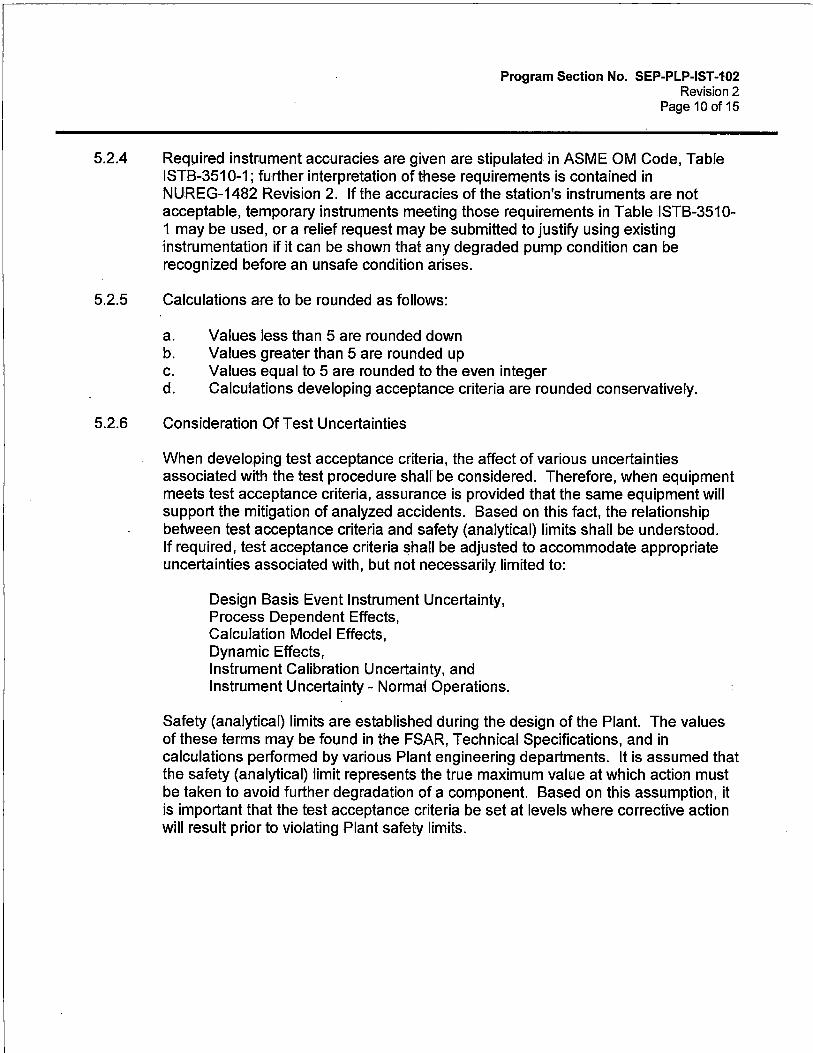
Program Section No. SEP~PLP-IST-102 Revision 2
Page 10of15
5.2.4 Required instrument accuracies are given are stipulated in ASME OM Code, Table ISTB-3510-1; further interpretation of these requirements is contained in NUREG-1482 Revision 2. If the accuracies of the station's instruments are not acceptable, temporary instruments meeting those requirements in Table ISTB-3510-1 may be used, or a relief request may be submitted to justify using existing instrumentation if it can be shown that any degraded pump condition can be recognized before an unsafe condition arises.
5.2.5 Calculations are to be rounded as follows:
a. Values less than 5 are rounded down b. Values greater than 5 are rounded up c. Values equal to 5 are rounded to the even integer d. Calculations developing acceptance criteria are rounded conservatively.
5.2.6 Consideration Of Test Uncertainties
When developing test acceptance criteria, the affect of various uncertainties associated with the test procedure shall be considered. Therefore, when equipment meets test acceptance criteria, assurance is provided that the same equipment will support the mitigation of analyzed accidents. Based on this fact, the relationship between test acceptance criteria and safety (analytical) limits shall be understood. If required, test acceptance criteria shall be adjusted to accommodate appropriate uncertainties associated with, but not necessarily limited to:
Design Basis Event Instrument Uncertainty, Process Dependent Effects, Calculation Model Effects, Dynamic Effects, Instrument Calibration Uncertainty, and Instrument Uncertainty - Normal Operations.
Safety (analytical) limits are established during the design of the Plant. The values of these terms may be found in the FSAR, Technical Specifications, and in calculations performed by various Plant engineering departments. It is assumed that the safety (analytical) limit represents the true maximum value at which action must be taken to avoid further degradation of a component. Based on this assumption, it is important that the test acceptance criteria be set at levels where corrective action will result prior to violating Plant safety limits.

5.3 DAT A EVALUATION
Program Section No. SEP-PLP-IST-102 Revision 2
Page 11 of 15
5.3.1 The initial evaluation of Technical Specification Surveillance test data and determination of pump operability is conducted by the operator who performed the test and is reviewed by the Shift Manager. Individual pump Technical Specifications require this evaluation to be done as soon as possible, usually by the end of the shift in which the data was taken, in order to meet possible Limiting Condition of Operation (LCO) requirements. If the data is not available before the end of the shift, then the oncoming shift will make the determination. A follow-up evaluation is performed by the IST Coordinator or his designee to monitor trends in pump hydraulic performance (pump d/p, flowrate, and speed) and mechanical performance (vibrations). In addition, when the test results are used as new reference values, such as after maintenance or for a new system configuration, the IST Coordinator must evaluate and verify that the new values represent acceptable pump performance. In the latter case, a revision to the record of tests may be required. Therefore, the follow up IST review should be conducted in a timely manner.
Following data evaluation, the IST Coordinator notes any abnormal conditions under remarks, signs the completed test, and forwards the test to the System Engineer for identification and completion of necessary corrective action.
5.3.2 The allowable ranges for the pump operating parameters are defined in Attachment 2. These ranges are based on the ranges provided in ASME OM Code, Tables ISTB 5121-1, ISTB-5222-1, ISTB-5321-1 and ISTB-5321-2.
If deviations fall within the alert range, the frequency of testing specified for the pump (in Attachment 3) shall be doubled until the cause of the deviation is determined and the condition corrected. If deviations fall within the required action range, the pump shall be declared inoperable until the cause of the deviation has been determined and the condition corrected. If any measured parameter falls within the required action range, the evaluator shall initiate corrective action per Section 5.4 below.
When a test shows deviations outside of the acceptable range, the instruments involved may be recalibrated and the test rerun. If during the test, it becomes obvious that the instrument is malfunctioning, the test may be halted and the instruments promptly recalibrated. Care should be taken to ensure that the noted deviations are due to the gauge and not a result of degraded pump performance or a system related problem.

Program Section No. SEP-PLP-IST-102 Revision 2
Page 12of15
5.3.3 Where available, the data sheets require that motor currents, voltages, and other data be recorded as an additional aid for pump performance evaluation. Although this information is not required by ASME OM Code, the IST Coordinator should consider using this information and/or obtaining similar data from other pumps when necessary to evaluate a change in pump operating parameters. This data is not compared to acceptance criteria and should not lead to a pump being declared inoperable unless the supporting parameter has other specific acceptance limits which affect pump operability.
Testing data necessary to determine pump head capacity, efficiency, and break horsepower shall be made available upon request and anytime changes to test parameters are approved. Such data is necessary to maintain the Diesel Generator Steady State Load Analysis.
5.3.4 If adverse trends are detected in pump parameters, the reviewers should attempt to predict when the parameter will enter the alert or required action ranges. This prediction should then be used to schedule necessary maintenance during a convenient outage or when practical.
5.3.5 Through the performance of the review following repair or replacement of a pump, new reference values and acceptance criteria may be required, as identified in Step 5.2.2. This change is to be accomplished per Palisades Administrative Procedure 10.41, "Site Procedure and Policy Processes."
5.4 CORRECTIVE ACTION
5.4.1 Any variation of a measured parameter falling within the specified Required Action Range shall be documented on a corrective action document for identification and evaluation.
5.4.2 If a measured parameter falls within the specified Required Action Range, the pump shall be declared inoperable and identified to prevent its use, except in an emergency, until either the cause of the deviation has been determined and the condition is corrected, or an analysis of the pump is performed and new reference values are established. [ISTB-6200(a)]
5.4.3 If the measured test parameter values fall within the alert range the frequency of testing shall be doubled until the cause of the deviation is determined and the condition is corrected. [ISTB-6200(b)]
5.4.4 In cases where the pump's test parameters are within either the alert or required action ranges, and the pump's continued use at the changed values is supported by an analysis, a new set of reference values may be established. This analysis shall include verification of the pump's operational readiness. The analysis shall include both a pump level and a system level evaluation of operational readiness, the cause of the change in pump performance, and an evaluation of all trends indicated by

Program Section No. SEP-PLP-IST-102 Revision 2
Page 13of15
available data. The results of this analysis shall be documented in the record of tests. [ISTB-6200]
5.4.5 When a test shows measured parameter values that fall outside of the acceptable range that have resulted from an identified systematic error, such as improper system lineup or inaccurate instrumentation, the test shall be rerun after correcting the error. [ISTB-6300]
5.5 TRENDING
5.5.1 The results of the quarterly or biennial comprehensive inservice tests for each pump shall be recorded on trending program(s) in a format adequate to identify trends in pump performance [ISTB-6100]. As a minimum, parameters to be recorded in the pump record include (actual measured values are preferred to calculated values):
a. Pump speed (for variable speed pumps only).
b. Pump differential pressure (except for positive displacement pumps) as calculated (measured discharge pressure minus calculated or measured suction pressure), or as directly measured. [RLR]
c. Pump Discharge Pressure (for positive displacement pumps only).
d. Pump flow rate. [RLR]
e. Pump vibration.
f. Entries referencing significant maintenance actions or other pertinent comments.
5.5.2 When the required action limits for pump parameters change, the IST Coordinator must ensure that the specified test procedure limits are also changed to appropriate new values. Since the first level Shift Manager review provides immediate verification of pump operability, these limits shall be kept current. The IST Coordinator shall notify the TSSPA of any revisions to pump tests, which must be completed by the next inservice test interval. Attachment 5, "lnservice Testing Program Pump Reference Value/Ranges Change Form" (or equivalent) should be used as the engineering evaluation to establish, calculate, and evaluate any new reference values and acceptance limits.

6.0 RECORDS AND ATTACHMENTS
6.1 RECORDS
Program Section No. SEP-PLP-IST-102 Revision 2
Page 14of15
6.1.1 A record is maintained for each pump covered in the IST Program. The records include the following:
a. The pump manufacturer and associated model numbers and serial numbers, or other identification numbers, are maintained in the Plant Equipment Data Base.
b. A copy or summary of the manufacturer's acceptance test report, and a copy of the pump manufacturer's operating limit, if available. This information is contained in the appropriate pump vendor file.
6.1.2 Each individual test procedure is considered a record and .is controlled by Administrative Procedure 10.41 "Site Procedure And Policy Processes." Each test procedure includes the following:
a. The hydraulic test circuit to be used, either in textual and/or diagrammatic form.
b. The location and type of measurement for each of the required test quantities.
c. The reference values, limits, and any other values required per ASME OM Code, Subsection ISTB and/or Technical Specifications.
6.1.3 Each completed test is considered a record and is controlled by Administrative Procedure 9.20 "Technical Specification Surveillance and Special Test Program." Each completed test procedure includes the following:
a. Pump identification
b. Date of test.
c. Reason for test.
d. Test procedure that was used
e. Identification of instruments used.
f. Calibration records or identification of calibrated equipment
g. Values of measured and observed parameters.
h. Comparisons with allowable ranges of test values and analysis of deviations.

i. Requirement for corrective action.
Program Section No. SEP-PLP-IST-102 Revision 2
Page 15of15
j. Evaluation and justification for changes to reference values.
k. Signature of the person or persons responsible for conducting and analyzing the test.
6.1.4 Corrective actions required by the ASME OM Code are considered records and are controlled in accordance with Entergy Procedure EN-Ll-102, "Corrective Action Process". lnservice Testing related corrective actions include the following:
a. Summary of the corrective actions made
b. lnservice Test used for conformation of operational adequacy
c. Identification of the person(s) responsible for the corrective action
6.2 ATTACHMENTS
6.2.1 Attachment 1, "Pump Testing System Index"
6.2.2 Attachment 2, "Allowable Ranges of Test Quantities"
6.2.3 Attachment 3, "Pump Test Plan"
6.2.4 Attachment 4, "Group A and B Pump Test Hydraulic Circuits"
6.2.5 Attachment 5, "IST Pump Reference Value(s)/Range(s) Change Form"
6.2.6 Attachment 6, "Pump Summary Listing"

k ::':\SYStEMS : .. · · '•
Service Water
Auxiliary Feedwater
'
Component Cooling
Containment Spray
HP Safety Injection
LP Safety Injection
Diesel Jacket Water Cooling
TABLE 1
Program Section No. SEP-PLP-IST-102 ATTACHMENT 1
Revision 2 Page 1of1
PUMP TESTING SYSTEM INDEX
·PUMP.NO> .. : ; ; ···· 'GROUP" {(" :.•;~:./•,?:. . . . ;, <.,DRAWING\" "'. :::COORDINATES . P-7A A M-21.3 F-3 P-78 A M-213 F-2 P-7C A M-213 F-1 P-8A 8 M-207-2 E-6 P-88 8 M-207-2 H-6 P-8C A M-207-2 8-6 P-52A A M-209-3 C-4 P528 A M-209-3 8-4 P52C A M-209-3 A-4 P-54A 8 M-204-1A D-5 P-548 8 M-204-1 8-3 P-54C 8 M-204-1 D-3 P-66A A M-204-1A 8-5 P-668 A M-204-1 F-3 P-67A A M-204-1A E-5 P-678 A M-204-1 E-3
P-211A Skid M-214-1 8-3 P-2118 Skid M-214-1 8-3
Includes those Class 1, 2, and 3 pumps important to reactor and spent fuel safety which transfer automatically and restart on an emergency power supply under accident conditions.
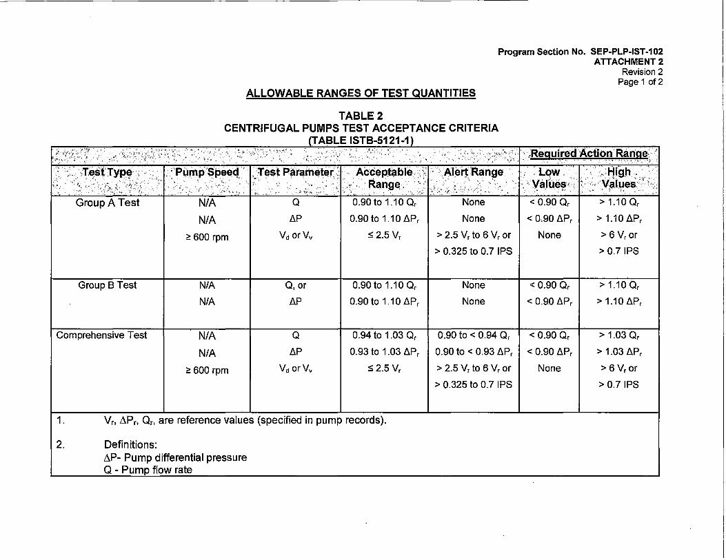
Program Section No. SEP-PLP-IST-102 ATTACHMENT 2
Revision 2 Page 1 of 2
ALLOWABLE RANGES OF TEST QUANTITIES
TABLE 2 CENTRIFUGAL PUMPS TEST ACCEPTANCE CRITERIA
Group A Test N/A
N/A
<:: 600 rpm
Group B Test NIA
N/A
Comprehensive Test N/A
N/A
<:: 600 rpm
TABLE ISTB-5121-1
;Test· Pararriet~r. : · · .. Accf:!pfable ..• · · · ··· · Range.· · ·
0 0.90 to 1.10 Or
LlP 0.90 to 1.10 LlPr
Vd orVv S2.5 Vr
0, or 0.90 to 1.10 Or
LlP 0.90to 1.10LlPr
0 0.94 to 1.03 Or
LlP 0.93 to 1.03 LlPr
Vd orVv ::s; 2.5 Vr
1. Vr, L\Pr, Or, are reference values (specified in pump records).
2. Definitions: L\P- Pump differential pressure Q - Pum flow rate
None
None
> 2.5 Vr to 6 Vr or
> 0.325 to 0.7 IPS
None
None
0.90 to< 0.94 Or
0.90 to < 0.93 LlPr
> 2.5 Vr to 6 Vr or
> 0.325 to 0.7 IPS
\Required Action Range " " . - - . . ' ··~ : " " ~ !' ; ; . ·~
. 1.c:)w ::.11 igh . ';\Values,··, • > ·values.'·
, .:_.~ • :' ">
< 0.90 Or > 1.10 Or
< 0.90 LlPr > 1.10 LlPr
None > 6 Vr or
> 0.7 IPS
< 0.90 Or > 1.10 Or
< 0.90 LlPr > 1.10 LlPr
< 0.90 Or > 1.03 Or
< 0.90 LlPr > 1.03 LlPr
None > 6 Vr or
> 0.7 IPS
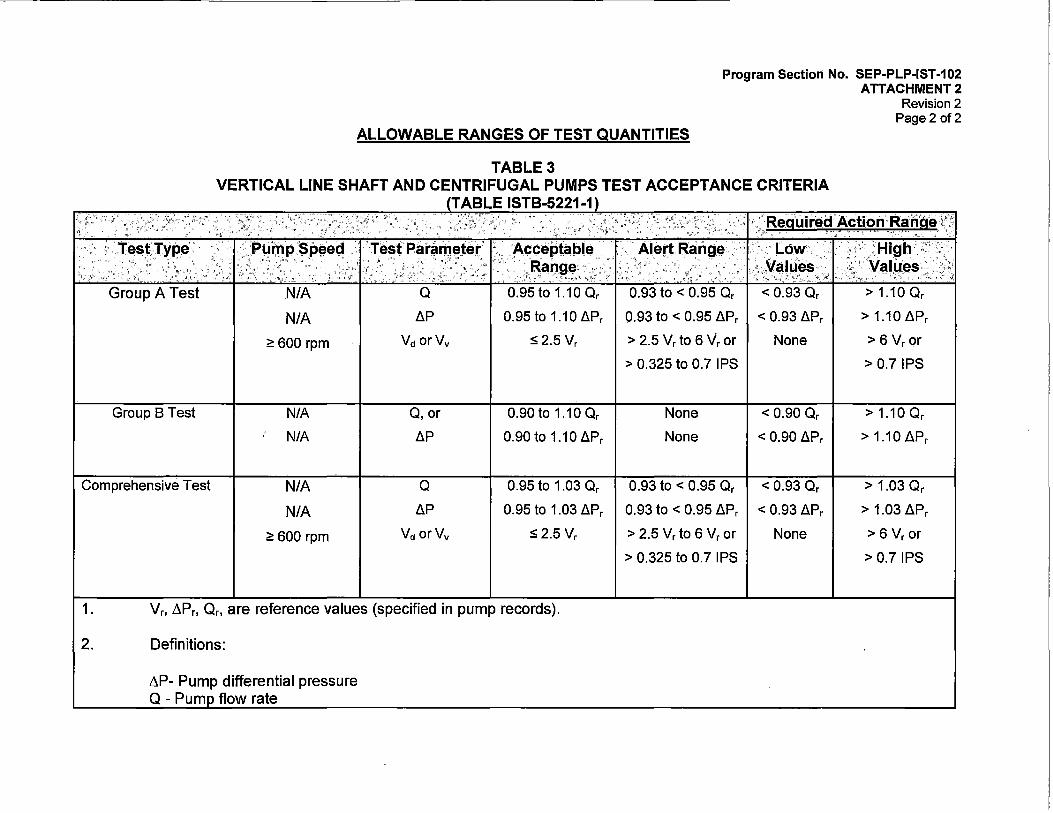
Program Section No. SEP-PLP-IST-102 ATTACHMENT 2
Revision 2 Page 2 of2
ALLOWABLE RANGES OF TEST QUANTITIES
TABLE 3 VERTICAL LINE SHAFT AND CENTRIFUGAL PUMPS TEST ACCEPTANCE CRITERIA
Group A Test
Group B Test
N/A
N/A
~ 600 rpm
N/A
N/A
Comprehensive Test N/A
N/A
~ 600 rpm
o LlP
Vd orVv
0, or
LlP
o LlP
Vd orVv
TABLE ISTB-5221-1
0.95to 1.10 Or
0.95 to 1.10 LlPr
S2.5Vr
0. 90 to 1.10 Or
0.90to 1.10LlPr
0.95 to 1.03 Or
0.95 to 1.03 LlPr
s 2.5 Vr
1. Vr. ~Pr, Or, are reference values (specified in pump records).
2. Definitions:
~P- Pump differential pressure Q - Pum flow rate
'< ., .,
.. ..
0.93 to < 0.95 Or < 0.93 Or
0.93 to < 0.95 LlPr < 0.93 LlPr
> 2.5 Vr to 6 Vr or None
> 0.325 to 0.7 IPS
None < 0.90 Or
None < 0.90 LlPr
0.93 to < 0.95 Or < 0.93 Or
0.93 to < 0.95 LlPr < 0.93 LlPr
> 2.5 Vr to 6 Vr or None
> 0.325 to 0.7 IPS
> 1.10 Or
> 1.10 LlPr
> 6 Vr or
> 0.7 IPS
> 1.10 Or
> 1.10 LlPr
> 1.03 Or
> 1.03 LlPr
> 6 Vr or
> 0.7 IPS

SYSTEM
Service Water
Auxiliary Feedwater
Component Cooling Water
Containment Spray
High Pressure Safety Injection Pumps
Low Pressure Safety Injection Pumps
Diesel Jacket Water Cooling Pumps
PUMP
P7A P7B P7C
P8A P8B P8C
P52A P52B P52C
P54A P54B P54C
P66A P66B
P67A P67B
P211A P211B
Definitions: N Pump Speed (variable Speed Pump only) ~p Differential Pressure Q Flow Rate
TABLE 4 PUMP TEST PLAN
PUMP LISTING
SURV PROC NO CLASS
Q0-14 3 Q0-14 3 Q0-14 3
Q0-21 3 Q0-21 3 Q0-21 3
Q0-15 3 Q0-15 3 Q0-15 3
Q0-16 2 Q0-16 2 Q0-16 2
Q0-19 2 Q0-19 2
Q0-20 2 Q0-20 2
M0-7A-1 3 M0-7A-2 3
V Vibration (Displacement or Velocity as appropriate)
FREQ
Q Q Q
Q Q Q
Q Q Q
Q Q Q
Q Q
Q Q
M M
NOTE 1: Shaft Speed is not measured for pumps directly coupled to synchronous or induction type motors.
NOTE 2: Diesel Jacket Water Cooling Pumps are tested with the Diesel Generator skid.
Program Section No. SEP-PLP-IST-102 ATTACHMENT 3
Revision 2 Page 1of2
N AP Q v (1) x x x (1) x x x (1) x x x
(1) x x x x x (1) x x x
(1) x x X [RLR] (1) x x ·X [RLR] (1) x x X [RLR]
(1) x x (1) x x (1) x x
(1) x x x (1) x x x (1) x x x (1) x x x (2) (2) (2) (2) [RLR] (2) (2) (2) (2) [RLR]
NOTE 3: Although the component cooling water pumps are tested on a frequency of every three months and the diesel jacket cooling water pumps are tested monthly, the Renewed License only requires testing every eighteen months for aging management of components.

SYSTEM PUMP
Service Water P7A P7B P7C
Auxiliary Feedwater P8A P8B P8C
Component Cooling Water P52A P52B P52C
Containment Spray P54A P54B P54C
High Pressure Safety P66A Injection Pumps P66B
Low Pressure Safety Injection P67A Pumps P67B
Diesel Jacket Water P211A Cooling Pumps P211B
Definitions: N Pump Speed (variable Speed Pump only) AP Differential Pressure Q Flow Rate
TABLE 4 PUMP TEST PLAN
PUMP LISTING
SURV PROC NO CLASS
R0-144 3 R0-144 3 R0-144 3
R0-145 3 R0-145 3 R0-145 3
R0-146 3 R0-146 3 R0-146 3
R0-98 2 R0-98 2 R0-98 2
R0-147 2 R0-147 2
R0-98 2 R0-98 2
M0-7A-1 3 M0-7A-2 3
V Vibration (Displacement or Velocity as appropriate)
FREQ
18MO 18MO 18MO
2YR 2YR 2YR
2YR 2YR 2YR
18MO 18MO 18MO
2YR 2YR
18MO 18MO
M M
NOTE 1: Shaft Speed is not measured for pumps directly coupled to synchronous or induction type motors.
NOTE 2: Diesel Jacket Water Cooling Pumps are tested with the Diesel Generator skid.
N
(1) (1) (1)
(1) x (1)
(1) (1) (1)
(1) (1) (1)
(1) (1)
(1) (1)
(2) (2)
Program Section No. SEP-PLP-IST-102 ATTACHMENT 3
Revision 2 Page 2 of 2
AP Q v x x x x x x x x x
x x x x x x x x x
x x x x x x x x x
x x x x x x x x x
x x x x x x
x x x x x x (2) (2) (2) (2) (2) (2)

Program Section No. SEP-PLP-IST-102 ATTACHMENT 4
Revision 2 Page 1of16
GROUP A AND B PUMP TEST HYDRAULIC CIRCUITS
SERVICE WATER SYSTEM TEST FLOWPATH
PUMP P-7A/ Group A I TEST PROC NO Q0-14 I P&ID: M-213/F3
MV-SW661
MV-SW342
P-7A I MV-SW341
J SUMP PIT
s·ERVICE WATER PUMPS
The. Service Water Pumps have an active safety function to supply cooling water to essential loads during an accident as well as during normal Plant power operations. The SWS pumps start automatically upon receipt of a Safety Injection Signal (SIS). Each SWS pump delivers essentially 50% capacity, although one pump may be adequate during particular scenarios. The power supply to this pump is 2400 VAC bus 1 D.
PARAMETER REFERENCE SET INSTRUMENT
SPEED CONSTANT RPM ,N/A INLET PRESS (1) VARIABLE PSI LIT-1338
DISCHARGE PRESSURE (1) VARIABLE PSI Pl-1322 DIFFERENTIAL PRESSURE 99.9 PSID CALCULATED
FLOW RATE 2000 GPM Fl-1347 VIBRATION MULTIPLE IPS-PK M&TE
(1) Inlet and discharge pressure are required for calculation of pump differential pressure.

Program Section No. SEP-PLP-IST-102 ATTACHMENT 4
Revision 2 Page 2 of 16
GROUP A AND 8 PUMP TEST HYDRAULIC CIRCUITS
SERVICE WATER SYSTEM TEST FLOWPATH
PUMP P-7B/ Group A
P-78 MV-SW660
I TEST PROC NO Q0-14 I !Fl' \1347
MV-SW661
'"
tV-SW662
P&ID: M-213/F2
I MV-SW341
J SUMP PIT
SERVICE WATER PUMPS
The Service Water Pumps have an active safety function to supply cooling water to essential loads during an accident as well as during normal Plant power operations. The SWS pumps start automatically upon receipt of a Safety Injection Signal (SIS). Each SWS pump delivers essentially 50% capacity, although one pump may be adequate during particular scenarios. The power supply to this pump is 2400 VAC bus 1 C.
PARAMETER
SPEED INLET PRESS (1)
DISCHARGE PRESSURE (1) DIFFERENTIAL PRESSURE
FLOW RATE VIBRATION
REFERENCE SET
CONSTANT RPM VARIABLE PSI VARIABLE PSI
101.1 PSID 2000 GPM
MULTIPLE IPS-PK
INSTRUMENT
N/A LIT-1338 Pl-1321
CALCULATED Fl-1347 M&TE
(1) Inlet and discharge pressure are required for calculation of pump differential pressure.

ProgramSection No. SEP-PLP-IST-102 ATTACHMENT 4
Revision 2 Page 3of16
GROUP A AND B PUMP TEST HYDRAULIC CIRCUITS
SERVICE WATER SYSTEM TEST FLOWPATH
P-7C
PUMP P-7C/ Group A I TEST PROC NO Q0-14
/Pl' \1320_
MV-SW607A
MV-SW661
MV-SW607
F-2C MV-SW344
MV-SW663
Pl 1348
~~:- ~ ~
SERVICE WATER PUMPS
I P&ID: M-213/F1
MV-SW341
SUMP PIT
The Service Water Pumps have an active safety function to supply cooling water to essential loads during an accident as well as during normal Plant power operations. The SWS pumps start automatically upon receipt of a Safety Injection Signal (SIS). Each SWS pump delivers essentially 50% capacity, although one pump may be adequate during particular scenarios. The power supply to this pump is 2400 VAC bus 1 D.
PARAMETER REFERENCE SET INSTRUMENT
SPEED CONSTANT RPM N/A INLET PRESS (1) VARIABLE PSI LIT-1338
DISCHARGE PRESSURE (1) VARIABLE PSI Pl-1320 DIFFERENTIAL PRESSURE 100.7 PSID CALCULATED
FLOW RATE 2000 GPM Fl-1347 VIBRATION MULTIPLE IP.S-PK M&TE
(1) Inlet and discharge pressure are required for calculation of pump differential pressure.

Program Section No. SEP-PLP-IST-102 ATTACHMENT 4
Revision 2 Page 4 of 16
GROUP A AND B PUMP TEST HYDRAULIC CIRCUITS
SERVICE WATER SYSTEM TEST FLOWPATH
PUMP P-8A/ Group B I TEST PROC NO Q0-21 I P&ID: M-207-2/E6
CONDEIU3AT1t STORAGE
TANI<
T-2
MV-CD143
MV·FW133
P·BA
AUXILIARY FEEDWATER PUMPS The Auxiliary Feedwater Pumps have an active safety function to supply 100% of the required AFW flow during accident and normal startup and shutdown conditions. AFW flow is required whenever the main feedwater system is unavailable following a loss of offsite power, main feed line break, or a steam line break. These pumps start automatically upon receipt of an Auxiliary Feedwater Actuation Signal (AFAS). Flow from these pumps can be directed to either or both Steam Generators. P-8A is powered from safety-related 2400 VAC bus 1C.
PARAMETER REFERENCE SET INSTRUMENT
SPEED CONSTANT RPM N/A INLET PRESS (1) VARIABLE PSI Pl-0783
DISCHARGE PRESSURE (1) VARIABLE PSI Pl-0782 DIFFERENTIAL PRESSURE 1530 PSID CALCULATED
FLOW RATES 78GPM Fl-0783A VIBRATION MULTIPLE IPS-PK M&TE
(1) Inlet and discharge pressure are required for calculation of pump differential pressure.

Program Section No. SEP-PLP-IST-102 ATTACHMENT 4
Revision 2 Page 5of16
GROUP A AND B PUMP TEST HYDRAULIC CIRCUITS
AUXILIARY FEEDWATER SYSTEM TEST FLOWPATH
PUMP P-8B/ Group B
CONDl:NSi6.TE STOAAG~
TANK T-2
I TEST PROC NO Q0-21
MV-FW673
't---D<::~i...---. MV-CD143
P~SB
AUXILIARY FEEDWATER PUMPS
I P&ID: M-207-2/HS
The Auxiliary Feedwater Pumps have an active safety function to supply 100% of the required AFW flow during accident and normal startup and shutdown· conditions. AFW flow is required whenever the main feedwater system is unavailable following a loss of offsite power, main feed line break, or a steam line break. These pumps start automatically upon receipt of an Auxiliary Feedwater Actuation Signal (AFAS). Flow from these pumps can be directed to either or both Steam Generators. P-8B is turbine driven using steam from SIG E-50A.
PARAMETER REFERENCE SET INSTRUMENT
SPEED 3560 RPM M&TE INLET PRESS (1) VARIABLE PSI Pl-0782
DISCHARGE PRESSURE (1) VARIABLE PSI Pl-0783 DIFFERENTIAL PRESSURE 1509 PSID CALCULATED
FLOW RATES 65GPM Fl-0783B VIBRATION Not Required Not Required

Program Section No. SEP-PLP-IST-102 ATTACHMENT 4
Revision 2 Page6of16
GROUP A AND B PUMP TEST HYDRAULIC CIRCUITS
AUXILIARY FEEDWATER SYSTEM TEST FLOW PATH
PUMP P-8C/ Group A
CONOENSA.TE STORAGE
TANK
T-2
I
'------t' MV-00143
TEST PROC NO Q0-21 I P&ID: M-207-2/B6
TO SJG E50A
cv~m~i-o ~r~! s-~
MV-FW0752
CK·FW0726
P~ac
AUXILIARY FEEDWATER PUMPS
The Auxiliary Feedwater Pumps have an active safety function to supply 100% of the required AFW flow during accident and normal startup and shutdown conditions. AFW flow is required whenever the main feedwater system is unavailable following a loss of offsite power, main feed line break, or a steam line break. These pumps start automatically upon receipt of an Auxiliary Feedwater Actuation Signal (AFAS). Flow from these pumps can be directed to either or both Steam Generators. P-8C is powered from safety-related 2400 VAC bus 1D.
PARAMETER REFERENCE SET INSTRUMENT
SPEED CONSTANT RPM N/A INLET PRESS (1) VARIABLE PSI Pl-0762
DISCHARGE PRESSURE (1) VARIABLE PSI Pl-0750A DIFFERENTIAL PRESSURE 1040 PSID CALCULATED
FLOW RATES 165 GPM Fl-0736A 165 GPM Fl-0737A . 30.5 GPM Fl-0783C/Fl-0954
VIBRATION MULTIPLE IPS-PK M&TE

Program Section No. SEP-PLP-IST-102 ATTACHMENT 4
Revision 2 Page 7of16
GROUP A AND B PUMP TEST HYDRAULIC CIRCUITS
COMPONENT COOLING WATER RECIRC TEST FLOW PATH
PUMP P-52A/ Group A I
,...,.._--1..J MV~CC940
TEST PROC NO Q0-15 I P&ID: M-209-3/C4
TO PLANT 1----------.... coouNG MV-CCD916 MV-CC0914 \ LOADS
FROM PLANT _.,.....,--1_.-"I 1;1--4 COOLJNG
MV-CC919 MV-CC184 1.0ADS
COMPONENT COOLING WATER PUMPS
The Component Cooling Water Pumps are designed to maintain Plant cooling loads during normal operation and accident conditions. These pumps provide adequate cooling capability for the Safety Injection and Containment Spray water when it is recirculated through the Shutdown Cooling Heat Exchangers and for cooling the glands of the Safety Injection, Charging and Containment Spray Pumps. This pump is provided with 2400 VAC emergency power from bus 1 C.
PARAMETER REFERENCE SET INSTRUMENT
SPEED CONSTANT RPM N/A DIFFERENTIAL PRESSURE 83.0 PSID dPl-0918A
FLOW RATE (1) 6.0 PSID dPl-0918 6.0 PSID dPl-0919
VIBRATION MULTIPLE IPS-PK M&TE
(1) Flow rate is determined indirectly by setting heat exchanger E-54A and E-548 differential pressures to the specified reference value to obtain a flowrate of 4200 gpm.

Program Section No. SEP-PLP-IST-102 ATTACHMENT 4
Revision 2 Page 8of16
GROUP A AND B PUMP TEST HYDRAULIC CIRCUITS
COMPONENT COOLING WATER RECIRC TEST FLOW PATH
PUMP P-528/ Group A I TEST PROC NO Q0-15 I P&ID: M-209-3/84
-~
' (dPI\_ ' ~--~
-~ · \~ l TO PLANT
..;1 x (•coouNG CV-0946 E
MV-CC0916 \ LOADS MV-CC0914
'i' 548 ~;..-
CY-0945 IE 4j' 54A ...,.._. _ _____,~.,..._._ __
MV..oCC660 ,.,....._......_J' MV·CC942 I
.____. FROM PLANT -+-..... ....-.( . .,.,__.....COOLING
MV-CC920 MV-CC184 LOADS
COMPONENT COOLING WATER PUMPS \
The Component Cooling Water Pumps are designed to maintain Plant cooling loads during normal operation and accident conditions. These pumps provide adequate cooling capability for the Safety Injection and Containment Spray water when it is recirculated through the Shutdown Cooling Heat Exchangers and for cooling the glands of the Safety Injection, Charging and Containment Spray Pumps. This pump is provided with 2400 VAC emergency power from bus 1 D.
PARAMETER REFERENCE SET INSTRUMENT
SPEED CONSTANT RPM N/A DIFFERENTIAL PRESSURE 83 PSID dPl-09188
FLOW RATE (1) 6.0 PSID dPl-0918 6.0 PSID dPl-0919
VIBRATION MULTIPLE IPS-PK M&TE
(1) Flow rate is determined indirectly by setting heat exchanger E-54A and E-548 differential pressures to the specified reference value to obtain a flowrate of 4200 gpm.

Program Section No. SEP-PLP-IST-102 ATTACHMENT 4
Revision 2 Page 9 of 16
GROUP A AND B PUMP TEST HYDRAULIC CIRCUITS
COMPONENT COOLING WATER RECIRC TEST FLOW PATH
PUMP P-52C/ Group A I TEST PROC NO Q0-15 I P&ID: M-209-3/A4
. ,.,.__.......,,. MV-CC945 I
FROM PLANT _.._._,...,I -~1--4 COOUNG MV-CC921 MV-CC184 LOADS
P-52C
COMPONENT'COOLING WATER PUMPS
The Component Cooling Water Pumps are designed to maintain Plant cooling loads during normal operation and accident conditions. These pumps provide adequate cooling capability for the Safety Injection and Containment Spray water when it is recirculated through the Shutdown Cooling Heat Exchangers and for cooling the glands of the Safety Injection, Charging, and Containment Spray Pumps. This pump is provided with 2400 VAC emergency power from bus 1 C.
PARAMETER
SPEED DIFFERENTIAL PRESSURE
FLOW RATE (1)
VIBRATION
REFERENCE SET
CONSTANT RPM 83 PSID 6.0 PSID 6.0 PSID
MULTIPLE IPS-PK
INSTRUMENT
NIA dPl-0918C dPl-0918 dPl-0919
M&TE
(1) Flow rate is determined by indirectly setting heat exchanger E-54A and E-548 differential pressures to the specified reference value to obtain a flowrate of 4200 gpm.

Program Section No. SEP-PLP-IST-102 ATTACHMENT 4
Revision 2 Page 10of 16
GROUP A AND B PUMP TEST HYDRAULIC CIRCUITS
CONTAINMENT SPRAY SYSTEM TEST FLOWPATH
PUMP P-54A/ Group B I TEST PROC NO Q0-16
MVES106
CK3332 ,,-cv\
~ CK3233
Fl
0404
MV3232
MV3414 MVES614
P54A
CONTAINMENT SPRAY PUMPS
I P&ID: M-204-1A/D5
SIRW
TANK
T58
The Containment Spray Pumps have an active safety function to supply water to the Containment Spray Headers. The water is used to depressurize the Containment following a LOCA or Main Steam Line Break. P-54A starts automatically upon receipt of a Containment High Pressure Signal (CHP). The Containment Spray Pumps are designed to provide 50% of the required Containment Spray flow each, which provides on redundant 50% capacity pump. Pump P-54A is powered from 2400 VAC safety-related bus 1 D.
PARAMETER
SPEED DIFFERENTIAL PRESSURE
FLOW RATE VIBRATION
REFERENCE SET
CONSTANT RPM 227 PSID 260 GPM
MULTIPLE IPS-PK
INSTRUMENT
N/A dPl-0319A
Fl-0404 Not Required

Program Section No. SEP-PLP-IST-102 ATTACHMENT 4
Revision 2 Page 11 of 16
GROUP A AND B PUMP TEST HYDRAULIC CIRCUITS
CONTAINMENT SPRAY SYSTEM TEST FLOWPATH
PUMP P-54B/ Group B
CK3331
~ 7
CK3330
MV3222
I
CV 3056
DPI 03198
P54B
TEST PROC NO Q0-16
MVES106
0; \_o4o4
FT ) 0404
x ~
CONTAINMENT SPRAY PUMPS
I P&ID: M-204-1/B3
SIRW
TANK
T58
The Containment Spray Pumps have an active safety function to supply water to the Containment Spray Headers. The water is used to depressurize the Containment following a LOCA or Main Steam Line Break. P-54B starts automatically upon receipt of a Containment High Pressure Signal (CHP). The Containment Spray Pumps are designed to provide 50% of the required Containment Spray flow each, which provides on redundant 50% capacity pump. Pump P-54B is powered from 2400 VAC safety-related bus 1 C.
PARAMETER
SPEED DIFFERENTIAL PRESSURE
FLOW RATE VIBRATION
REFERENCE SET
CONSTANT RPM 225 PSID 260 GPM
MULTIPLE IPS-PK
INSTRUMENT
N/A dPl-0319B
Fl-0404 Not Required

Program Section No. SEP-PLP-IST-102 ATTACHMENT 4
Revision 2 Page 12of16
GROUP A AND B PUMP TEST HYDRAULIC CIRCUITS
CONTAINMENT SPRAY SYSTEM TEST FLOWPATH
PUMP P-54C/ Group B
CK3331
CK3330
MV3210
I
DPI 0319C
TEST PROC NO Q0-16
MVES106
MV3417
P54C
CONTAINMENT SPRAY PUMPS
I P&ID: M-204-1/03
SIRW
TANK
T58
The Containment Spray Pumps have an active safety function to supply water to the Containment Spray Headers. The water is use.d to depressurize the Containment following a LOCA or Main Steam Line Break. P-54C starts automatically upon receipt of a Containment High Pressure Signal (CHP). The Containment Spray Pumps are designed to provide 50% of the required Containment Spray flow each, which provides on redundant 50% capacity pump. Pump P-54C is powered from 2400 VAC safety-related bus 1 C.
PARAMETER
SPEED DIFFERENTIAL PRESSURE
FLOW RATE VIBRATION
REFERENCE SET
CONSTANT RPM 225 PSID 260 GPM
MULTIPLE IPS-PK
INSTRUMENT
NIA dPl-0319C
Fl-0404 Not Required

Program Section No. SEP-PLP-IST-102 ATTACHMENT 4
Revision 2 Page 13of16
GROUP A AND B PUMP TEST HYDRAULIC CIRCUITS
HIGH PRESSURE SAFETY INJECTION PUMPS RECIRC TEST FLOW PATH
PUMP P-66A/ Group A .
CK-3332
MV-ES102 (THROTTLcD)
I TEST PROC NO Q0-19 I
•'':'
P-66A
GL]_ ~ ~~
MV-3184 CK-3183
HIGH PRESSURE SAFETY INJECTION PUMPS
P&ID: M-204-1A/B5
SIRW
T58
Cl<~240
The High Pressure Safety Injection (HPSI) Pumps have an active safety function to supply primary makeup water in response to various accidents. The pumps start automatically upon receipt of a Safety Injection Signal (SIS) and may continue to operate to provide long term post accident cooling until Shutdown Cooling can be initiated. These pumps may be started manually by operators in response to a steam generator tube rupture. Each pump is designed to provide 100% of the required HPSI flow rate. The power supply to pump P-66A is safety-related 2400 VAC bus 1 D.
PARAMETER REFERENCE SET INSTRUMENT
SPEED CONSTANT RPM N/A INLET PRESS (1) VARIABLE PSI Pl-0326A
DISCHARGE PRESSURE (1) VARIABLE PSI Pl-0324 DIFFERENTIAL PRESSURE 1236 PSID CALCULATED
FLOW RATE 150 GPM Fl-0404 VIBRATION MULTIPLE IPS-PK Not Required

Program Section No. SEP-PLP-IST-102 ATTACHMENT 4
Revision 2 Page 14of16
GROUP A AND 8 PUMP TEST HYDRAULIC CIRCUITS
HIGH PRESSURE SAFETY INJECTION PUMPS RECIRC TEST FLOW PATH
PUMP P-66B/ Group A I
CK-3339
MV-3179
~ ~
{Pl\ \0325 J
P-668.
TEST PROC NO Q0-19
GL]_ ~ ~~
MV-3175 CK-3168
I P&ID: M-204-1/F3
StRW T58
CK-3239
HIGH PRESSURE SAFETY INJECTION PUMPS
The High Pressure Safety Injection (HPSI) Pumps have an active safety function to supply primary makeup water in response to various accidents. The pumps start automatically upon receipt of a Safety Injection Signal (SIS) and may continue to operate to provide long term post accident cooling until Shutdown Cooling can be initiated. These pumps may be started manually by operators in response to a steam generator tube rupture. Each pump is designed to provide 100% of the required HPSI flow rate. The power supply to pump P-66B is safety-related 2400 VAC bus 1 C.
PARAMETER REFERENCE SET INSTRUMENT
SPEED CONSTANT RPM N/A INLET PRESS (1) VARIABLE PSI Pl-0326B
DISCHARGE PRESSURE (1) VARIABLE PSI Pl-0324 DIFFERENTIAL PRESSURE 1240 PSID CALCULATED
FLOW RATE 150 GPM Fl-0404 VIBRATION MULTIPLE IPS-PK Not Required

Program Section No. SEP-PLP-IST-102 ATTACHMENT 4
Revision 2 Page 15of16
GROUP A AND B PUMP TEST HYDRAULIC CIRCUITS
LOW PRESSURE SAFETY INJECTION RECIRC TEST FLOW PATH
PUMP P-67A/ Group A I TEST PROC NO Q0-20 I P&ID: M-204-1A/E6
CK-3233
MV-ES611
P-67A
GLJ~ ~~
LOW PRESSURE SAFETY INJECTION PUMPS
SIRW
T58
The Low Pressure Safety Injection (LPSI) Pumps have an active safety function to supply primary makeup water in response to various accidents, as well as, provide cooling flow for either normal or post accident Shutdown Cooling. The pumps start automatically upon receipt of a Safety Injection Signal (SIS) or is started manually to enter Shutdown Cooling. The LPSI pumps are each designed to
·supply 100% of the required LPS I or Shutdown Cooling flow. The power supply to pump P-67 A is safety-related 2400 VAC bus 1 D.
PARAMETER REFERENCE SET INSTRUMENT
SPEED CONSTANT RPM N/A DIFFERENTIAL PRESSURE 187 PSID dPl-0323
FLOW RATE 190 GPM Fl-0404 VIBRATION MULTIPLE IPS-PK M&TE

Program Section No. SEP-PLP-IST-102 ATTACHMENT 4
Revision 2 Page 16of16
GROUP A AND 8 PUMP TEST HYDRAULIC CIRCUITS
LOW PRESSURE SAFETY INJECTION RECIRC TEST FLOW PATH
PUMP P-678/ Group A I TEST PROC NO Q0-20 I
CK-3330
MV-ES613
MV-3194
MV-ES612
LOW PRESSURE SAFETY INJECTION PUMPS
P&ID: M..:204-1/E3
SIRW
T58
CK-3239
CV-3031
The Low Pressure Safety Injection (LPSI) Pumps have an active safety function to supply primary makeup water in response to various accidents, as well as, provide cooling flow for either normal or post accident Shutdown Cooling. The pumps start automatically upon receipt of a Safety Injection Signal (SIS) or is started manually to enter Shutdown Cooling. The LPSI pumps are each designed to supply 100% of the required LPSI or Shutdown Cooling flow. The power supply to pump P-678 is safety-related 2400 VAC bus 1C.
PARAMETER REFERENCE SET INSTRUMENT
SPEED CONSTANT RPM N/A DIFFERENTIAL PRESSURE 186 PSID dPl~0322
FLOW RATE 190 GPM Fl-0404 VIBRATION MULTIPLE IPS-PK M&TE

Program Section No. SEP-PLP-IST-102 ATTACHMENT 5
Revision 2 Page 1of3
IST PUMP REFERENCE VALUE(S)/RANGE(S) CHANGE FORM
COMPONENT AND CODE IDENTIFICATION
Pump Component ID: --------
Pump Description:
Pump Category:
D Group A
D Group B
IST Parameter(s) Being Changed:
Applicable ASME Code: ASME OM Code 2004, OMb-2006, Subsection ISTA and ISTB.
REASON FOR REFERENCE VALUE/ACCEPTANCE CRITERIA CHANGE
Reason for the Reference Value/Acceptance Criteria Change:
D Pump Repair (ISTB-3310)
D Pump Replacement (ISTB-3310)
D Routine Servicing of a Pump (ISTB-3310)
D Establishment of Additional Set of Reference Values (ISTB-3320)
D Other:--------"'----------------------
Description of the reason for the Reference Value/Acceptance Criteria change:
BASIS FOR REFERENCE VALUE/ACCEPTANCE CRITERIA CHANGE
Test used to establish Reference Value/Acceptance Criteria:
D Preservice Test: -------------------Date: Work Order:
0 lnservice Test: Date: Work Order:
D Other: Date: Work Order:
Current IST Reference Value/Range
Use the applicable parameters in the table below to define the current IST reference value(s)/range(s).

Program Section No. SEP-PLP-IST-102 ATTACHMENT 5
Revision 2 Page2 of 3
IST PUMP REFERENCE VALUE(S)/RANGE(S) CHANGE FORM
PARAMETER REFERENCE ACCEPTABLE ALERT RANGE I REQUIRED VALUE RANGE ACTION RANGE
Differential Pressure (psid) Flowrate (gpm) Speed (rpm) P1X (IPS-PK P1Y (IPS-PK P1Z (IPS-PK P2X(IPS-PK P2Y (IPS-PK P2Z (IPS-PK M1X (IPS-PK) M1Y (IPS-PK) M1Z (IPS-PK M2X(IPS-PK M2Y (IPS-PK) M2Z (IPS-PK)
New IST Reference Value/Range
Use the applicable parameters in the table below to define the new IST reference value(s)/range(s).
PARAMETER REFERENCE ACCEPTABLE ALERTRANGE REQUIRED VALUE RANGE ACTION RANGE
Differential Pressure (psid) Flowrate (aom) Speed (rpm) P1X (IPS-PK) P1Y (IPS-PK) P1Z (IPS-PK) P2X (IPS-PK) P2Y (IPS-PK) P2Z (IPS-PK) M1X (IPS-PK) M1Y (IPS-PK) M1Z (IPS-PK) M2X (IPS-PK) M2Y (IPS-PK) M2Z (IPS-PK)
Does the pump have a minimum Technical Specification Value?
D Yes D No
Description of value:
Does the pump have a FSAR Design Basis Accident Value?
D Yes D No

Program Section No. SEP-PLP-IST-102 ATTACHMENT 5
Revision 2 Page 3 of 3
IST PUMP REFERENCE VALUE(S)/RANGE(S) CHANGE FORM
Description of value:
Basis for New IST Reference Value/Acceptance Criteria
ANALYSIS OF NEW REFERENCE VALUE/ACCEPTANCE CRITERIA
Analysis of deviations between the previous and new reference values:
Verification that the new reference value/ranges represent acceptable operation:
DOCUMENT UPDATES
Is a Surveillance Test Procedure Change Required?
D Yes D No
If Yes, document the procedure and ORN No.
Are Changes to Other Documents Required?
D Yes D No
If Yes, then Describe:
APPROVALS
Prepared by Qualified IST Engineer:
Name: Signature: Date:
Approved by:
Name: Signature: Date:

PUMP SUMMARY LISTING
Program Section No. SEP-PLP-IST-102 ATTACHMENT 6
Revision 2 Page 1 of6
The following table provides the details of the pumps that are in the scope of the lnservice Testing Program.
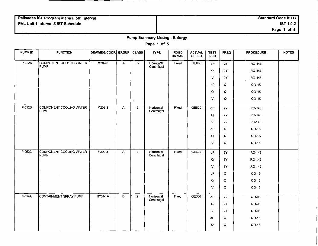
Palisades IST Program Manual 5th Interval PAL Unit 1 Interval 5 IST Schedule
PUMP ID FUNCTION DRAWING/COOR
P-052A COMPONENT COOLING WATER M209-3 PUMP
P-0528 COMPONENT COOLING WATER M209-3 PUMP
P-052C COMPONENT COOLING WATER M209-3 PUMP
P-054A CONTAINMENT SPRAY PUMP M204-1A
Pump Summary Listing - Entergy
Page 1 of 5
GROUP CLASS TYPE FIXED OR VAR.
A 3 Horizontal Fixed Centrifugal
A 3 Horizontal Fixed Centrifugal
A 3 Horizontal Fixed Centrifugal
B 2 Horizontal Fixed Centrifugal
ACTUAL TEST SPEED REQ
GE600 dP
Q
v
dP
Q
v
GE600 dP
Q
v
dP
Q
v
GE600 dP
Q
v
dP
Q
v
GE600 dP
Q
v
dP
Q
FREQ
2Y
2Y
2Y
Q
Q
Q
2Y
2Y
2Y
Q
Q
Q
2Y
2Y
2Y
Q
Q
Q
2Y
2Y
2Y
Q
Q
Standard Code ISTB
IST 1.0.2
Page 1 of 5
PROCEDURE NOTES
R0-146
R0-146
R0-146
Q0-15
Q0-15
Q0-15
R0-146
R0-146
R0-146
Q0-15
Q0-15
Q0-15
R0-146
R0-146
R0-146
Q0-15
Q0-15
Q0-15
R0-98
R0-98
R0-98
Q0-16
Q0-16

Palisades IST Program Manual 5th Interval PAL Unit 1 Interval 5 IST Schedule
PUMP ID FUNCTION DRAWING/COOR
P-0548 CONTAINMENT SPRAY PUMP M204-1
P-054C CONTAINMENT SPRAY PUMP M204-1
P-066A HIGH PRESSURE SAFETY M204-1A INJECTION PUMP
P-0668 HIGH PRESSURE SAFETY M204-1 INJECTION PUMP
Pump Summary Listing - Entergy
Page 2 of 5
GROUP CLASS TYPE FIXED OR VAR.
8 2 Horizontal Fixed Centrifugal
8 2 Horizontal Fixed Centrifugal
A 2 Horizontal Fixed Centrifugal
A 2 Horizontal Fixed Centrifugal
ACTUAL TEST SPEED REQ
GE600 dP
Q
v
dP
Q
GE600 dP
Q
v
dP
Q
GE600 dP
Q
v
dP
Q
v
GE600 dP
Q
v
dP
Q
v
FREQ
2Y
2Y
2Y
Q
Q
2Y
2Y
2Y
Q
Q
2Y
2Y
2Y
Q
Q
Q
2Y
2Y
2Y
Q
Q
Q
Standard Code ISTB IST 1.0.2
Page 2 of 5
PROCEDURE NOTES
R0-98
R0-98
R0-98
Q0-16
Q0-16
R0-98
R0-98
R0-98
Q0-16
Q0-16
R0-147
R0-147
R0-147
Q0-19
Q0-19
Q0-19
R0-147
R0-147
R0-147
Q0-19
Q0-19
Q0-19

Palisades IST Program Manual 5th Interval
PAL Unit 1 Interval 5 IST Schedule
PUMP ID FUNCTION DRAWING/COOR
P-067A LOW PRESSURE SAFETY M204-1A INJECTION PUMP
P-0678 LOW PRESSURE SAFETY M204-1 INJECTION PUMP
P-008A MOTOR DRIVEN AUXILIARY M207-2 FEEDWATER PUMP
Pump Summary Listing - Entergy
Page 3 of 5
GROUP CLASS TYPE FIXED OR VAR.
A 2 Horizontal Fixed Centrifugal
A 2 Horizontal Fixed Centrifugal
B 3 Horizontal Fixed Centrifugal
ACTUAL TEST SPEED REQ
GE600 dP
Q
v dP
Q
v
GE600 dP
Q
v dP
Q
v
GE600 dP
Q
v dP
Q
FREQ
2Y
2Y
2Y
Q
Q
Q
2Y
2Y
2Y
Q
Q
Q
2Y
2Y
2Y
Q
Q
Standard Code ISTB IST 1.0.2
Page 3 of 5
PROCEDURE NOTES
R0-98
R0-98
R0-98
Q0-20
Q0-20
Q0-20
R0-98
R0-98
R0-98
Q0-20
Q0-20
Q0-20
R0-145
R0-145
R0-145
Q0-21
Q0-21

Palisades IST Program Manual 5th Interval PAL Unit 1 Interval 5 IST Schedule
PUMP ID FUNCTION DRAWING/COOR
P-0088 STEAM DRIVEN AUXILIARY M207-2 FEEDWATER PUMP
P-008C MOTOR DRIVEN AUXILIARY M207-2 FEEDWATER PUMP
P-007A SERVICE WATER PUMP M213
Pump Summary Listing - Entergy
Page 4 of 5
GROUP CLASS TYPE FIXED ORVAR.
B 3 Centrifugal Var Horizontal
A 3 Horizontal Fixed Centrifugal
A 3 Vertical Line Fixed Shaft
Centrifugal
ACTUAL TEST SPEED REQ
GE600 dP
N
Q
v
dP
N
Q
GE600 dP
Q
v
dP
Q
v
GE600 dP
Q
v
dP
Q
v
FREQ
2Y
2Y
2Y
2Y
Q
Q
Q
2Y
2Y
2Y
Q
Q
Q
2Y
2Y
2Y
Q
Q
Q
Standard Code ISTB IST 1.0.2
Page 4 of 5
PROCEDURE NOTES
R0-145
R0-145
R0-145
R0-145
Q0-21
Q0-21
Q0-21
R0-145
R0-145
R0-145
Q0-21
Q0-21
Q0-21
R0-144
R0-144
R0-144
Q0-14
Q0-14
Q0-14

Palisades IST Program Manual 5th Interval PAL Unit 1 Interval 5 IST Schedule
PUMP ID FUNCTION DRAWING/COOR
P-0078 SERVICE WATER PUMP M213
P-007C SERVICE WATER PUMP M213
Pump Summary Listing - Entergy
Page 5 of 5
GROUP CLASS TYPE FIXED ORVAR.
A 3 Vertical Line Fixed Shaft
Centrifugal
'
A 3 Vertical Line Fixed Shaft
Centrifugal
ACTUAL TEST SPEED REQ
GE600 dP
Q
v dP
Q
v
GE600 dP
Q
v dP
Q
v
FREQ
2Y
2Y
2Y
Q
Q
Q
2Y
2Y
2Y
Q
Q
Q
Standard Code ISTB IST 1.0.2
Page 5 of 5
PROCEDURE NOTES
R0-144
R0-144
R0-144
Q0-14
Q0-14
Q0-14
R0-144
R0-144
R0-144
Q0-14
Q0-14
Q0-14

Palisades Nuclear Plant lnservice Testing (IST) Program Plan
Fifth Ten-Vear Interval
Section 5.0
Deferred Test Justifications
Page 245
(29 pages follow)

Pali$adf}s Pump and Valve .lnservice T~sting (IST) Program COLD SHUTDOWN JUSTIFICATION
CSJ-01
Component ID Class Cat System Label
PRV-1067 PRV-1068 PRV-1069 PRV-1070 PRV-1071 PRV-1072
FUNCTION:
1 1 1 1 1 1
B B a B B B
PCS PCS PCS PCS PCS PCS
Reactor Head Vent Valve Reactor Head Vent Valve Pressurizer Head Vent Valve Pressurizer Head Vent Valve Rx Head and Pressurizer Head Combined Vent Valve Rx Head and Pressurizer Head Combined Ve.nt Valve
the Reactor Head Vent Valves perform a safety function to OPEN during. a LOGA in order to vent gasses from the reactor vessel head. They perform a safety function in the CLOSED position to maintain Primary·Goolaht.System Integrity.·
The Pressurizer Head Vent Valves perform a safety function to OPEN during a LOCA in order to vent gasses from the pressurizer head. They perform a safety function in the CLOSED position to maintain Primary Coolant System Integrity.
The Rx Head and Pressurizer Head Combined Vent Valves perform a safety function to OPEN during a LOCA in order to vent gasses from the reactor vessel or pressurizer head. They perform a safety·function in the CLOSED position to maintain Primary Coolant System Integrity.
TEST REQUIREMENT:
ASME OMa-2005 ISTG-3521(c); if exercising is not practicable during operation at power, it may be limited to full-stroke exercising during cold shutdowns.
BASIS:
These valves are Reactor Coolant Pressure Boundary (RCPB) valves per the requirements of · 10 CFR 50.2. Testing these valves during reactor oper:ation would violate the two valve RCPB
isolation provi$ion of 10 CFR 50.2, Additionally, testing these valves quring operation with the PCS at normal operating temperature c;ind pressure would result in discharge of small amounts of radioactive steam to the containment atmosphere.
ALTERNATE TESTING:
Exercise during cold shutdowns, but not necessarily more frequently than once each quarter.
Remote Position Indication verification is performed each refueling outage and at least once every two years.
Page 1 of 29

Palisades Pump and Valve lnservice Testing (/ST) Program COLD SHUTDOWN JUSTIFICATION
CSJ-02
Component ID Class Cat System Label
CV-2083 2 A eve PCS Pumps Controlled Bleedoff Containment Isolation
CV-2099 2 A eve PCP P-50A, B, C & D Controlled Bleedoff
FUNCTION:
These valves have a safety function to CLOSE for Containment isolation of the primary coolant pump seal controlled bleedoff line to volume control tank.
CV-2083 and CV-2099 perform a safety function in the CLOSED position to isolate containment penetration 44 on a Containment High Pressure (CHP) Signal and/or a Containment High Radiation (CHR) Signal from the Containment Isolation system and a Safety Injection Signal, which are expected to occur as a result of a LOCA.
TEST REQUIREMENT:
ASME OMa-2005 ISTC-3521{c); if exercising is not practicable during operation at power, it may be limited to full-stroke exercising during cold shutdowns.
BASIS:
Shutting this valve during primary coolant pump operation (i.e., any hot Plant condition) stops pump seal leakoff flow and, subsequently, a loss of seal lubrication and cooling. This scenario could lead to a seal failure resulting in significant pump damage, and relief valve lift, resulting in the unnecessary loss of primary coolant as radioactive waste.
ALTERNATE TESTING:
Exercise during cold shutdowns, but not necessarily more frequently than once each quarter. Perform Position Indication Test at least once every two years. Leak testing is performed in accordance with 10 CFR 50.55, Appendix J, Local Leak Rate Test Program.
Page 2 of 29
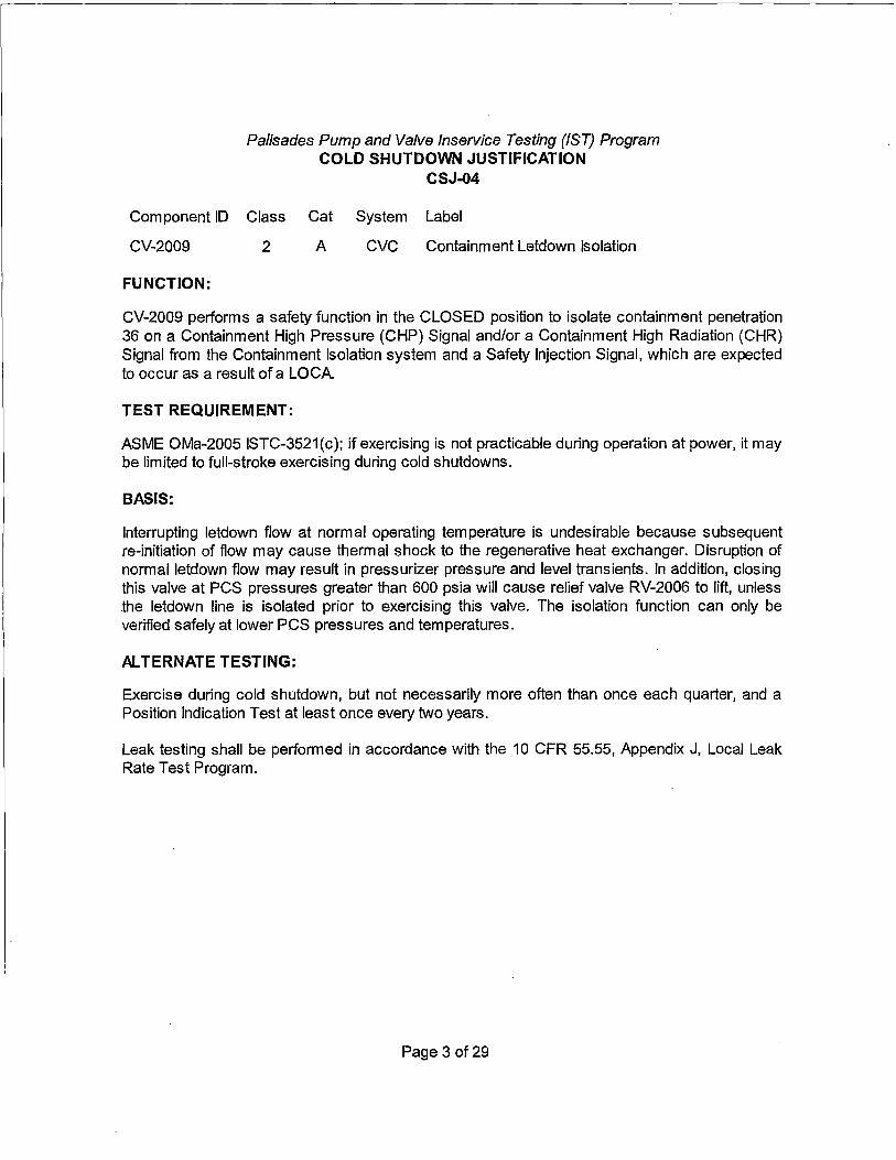
Palisades Pump and Valve lnservice Testing (/ST) Program COLD SHUTDOWN JUSTIFICATION
CSJ-04
Component ID Class Cat System Label
CV-2009 2 A CVC Containment Letdown Isolation
FUNCTION:
CV-2009 performs a safety function in the CLOSED position to isolate containment penetration 36 on a Containment High Pressure (CHP) Signal and/or a Containment High Radiation (CHR) Signal from the Containment Isolation system and a Safety Injection Signal, which are expected to occur as a result of a LOCA.
TEST REQUIREMENT:
ASME OMa-2005 ISTC-3521(c); if exercising is not practicable during operation at power, it may be limited to full-stroke exercising during cold shutdowns.
BASIS:
Interrupting letdown flow at normal operating temperature is undesirable because subsequent re-initiation of flow may cause thermal shock to the regenerative heat exchanger. Disruption of normal letdown flow may result in pressurizer pressure and level transients. In addition, closing this valve at PCS pressures greater than 600 psia will cause relief valve RV-2006 to lift, unless the letdown line is isolated prior to exercising this valve. The isolation function can only be verified safely at lower PCS pressures and temperatures.
ALTERNATE TESTING:
Exercise during cold shutdown, but not necessarily more often than once each quarter, and a Position Indication Test at least once every two years.
Leak testing shall be performed in accordance with the 10 CFR 55.55, Appendix J, Local Leak Rate Test Program.
Page 3 of 29
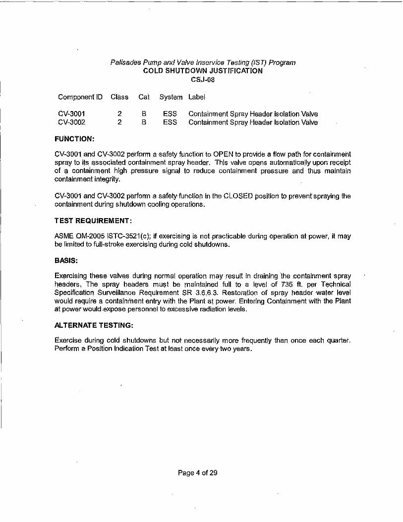
Palisades Pump and Valve /riservice Testing (/ST) Program COLD SHUTDOWN JUSTIFICATION
CS'J-08
Comp.oneht' ID Class Cat System Label
CV-3001 CV-3002
FUNCTION:
2 2
B B
ESS Containment Spray Header Isolation Valve ESS Containment Spray Header Isolation Valve
CV-3001 and CV-3002 perform a safety function to OPEN to provide a flow path for containment spray to its associated containment spray header. This valve opens automatically upon receipt of ~·containment high .press\;lre signal to reduce containment pressure and thus maintain containment integrity.
CV-3001 and CV-3002 perform a safety· function in the CLOSED position to prevent spraying the containment during shutdown cooling operations.
TEST REQUiREIViENT:
ASME OM-2005 ISTC-3521(c); if exercising is not practicable during operation at power, it may be limited to full-stroke exercising during cold shutdowns.
BASIS:
Exercising these valves during normal operation may result in draining 'the containment spray headers, The spray headers must be maintained full to a level of 735. ft. per Technical Specification Surveillance Requirement SR 3.!;i,6.3. Restoration of spray header water level would require a containment entry with the Plant a~ power. Entering Containment with the Plant at power would expose personnel to excessive radiation levels.
AL T~RNATE TESTING:
Exercise during cold shutdowns but riot necessarily more frequently than once each quarter. Perform a Position Indication Test at least once every two years.
Page 4 of 29

Pa/isa(les Pump and Valve fn$ervice Testing (/ST) Program COLD SHUTDOWN JUSTIFICATION
CSJ-10
Component ID Class Cat System Label
CV-~027 CV'-3056
FUNCTION:
2 2
A A
ESS ESS
SIRW Tank T-58 Recirculation SIRW Tank T-58 Reci'rculatioh Shutoff
cV;.;3027 and CV-3056 perform a safety function in the OPEN position to provide a minimum recirculation flow path to prevent damage to the low pressure and high pressure safety injection j:>Lim ps while primary coolant system pressure is higher than pump discharge pressure.
CV-3027 and CV-30q6 perform a safety function in the QLO$ED position t9 prevent pumping contaminated water from the containment sump to the safety injection and refueling W<:lter tank following a recirculation actuation signal (RAS). Thes.e valves must also limit leakage back to the S IRW Tank that co1,.1ld lead to releases of radionuclides in excess of those allowed.·
TEST REQUIREMENT:·
ASME 0~2005 ISTC-3521(c); if exercising is not practicable during opE;iration Git power, it may be limited to full-stroke exercising during cold shutdowns.
BASIS:
These normally open valves isolate the minimum flow recircuiaticm lines for all ECCS pumps. For the period of tinte either of these valves are closed, both ECCS trains are inoperable, which is not allowed by technical specification. As such •. an immediate Plant shutdown wou.ld be required when either·valve is closed.
ALTER,NATE TESTING:
Exercise during cold shutdowns but not necessarily more frequently than once each quarter. Perform a Position ·Indication Test atleast once every two years.
Page 5of29

Palisades Pump and Valve lnservice Testing (/ST) Program COLD SHUTDOWN JUSTIFICATION
CSJ-13
Component ID Class Cat System Label
CV-3031 CV-3057
FUNCTION:
2 2
A A
ESS ESS
SIRW Tank T-58 Outlet Isolation SIRW Tank T-58 Discharge Shutoff Valve
CV-3031 and CV-3057 perform a safety function in the OPEN position to provide a flow path from the safety injection and refueling water tank to the suction of the low pressure safety injection pumps, the high pressure safety injection pumps, and the containment spray pumps.
CV-3031 and CV-3057 perform a safety function in the CLOSED position to prevent a loss of suction to the safety injection and containment spray pumps.
TEST REQUIREMENT:
ASME OM-2005 ISTC-3521(c); if exercising is not practicable during operation at power, it may be limited to full-stroke exercising during cold shutdowns.
BASIS:
Exercising CV-3031 and CV-3057 eliminates the suction source of one ECCS train. Exercising CV-3031 eliminates the suction source for P-668 HPSI Pump and P-678 LPSI Pump, as well as P-548 and P-54C CTMT Spray Pumps. Exercising CV-3057 eliminates the suction source for P-66A HPSI Pump and P-67A LPSI Pump and p.:54A CTMT Spray Pump. To preclude equipment failure should a coincidental ESS actuation occur while either CV-3031 (or CV-3057) is closed, Operations would have to manually disable all 4 (3) pumps by removing their breaker control power fuses, and then they would have to subsequently test-start all 4 (3) pumps to verify operability in accordance with administrative procedures. In addition to entry into a 72 hour action statement, the potential for equipment failure (fuse, breaker) and/or human performance error is increased. The additional equipment and human performance failures associated with stroke-testing either CV-3031 (T-58 to West Safeguards) or CV-3057 (T-58 to East Safeguards) introduces a risk that is not commensurate with the benefit of stroking these valves above cold shutdown (Mode 5). Therefore, these valves will be exercised at cold shutdowns.
ALTERNATE TESTING:
Exercise during cold shutdowns but not necessarily more frequently than once each quarter. Perform a Position Indication Test at least once every two years.
Page 6of29

Palisades Pump and Valve lnservice Testing (/ST) Program . COLD SHUTDOWN JUSTIFICATION
CSJ-14
Component ID Class Cat System Label
CV-3029 CV-3030
FUNCTION:
2 2
B B
ESS ESS
Containment Sump Isolation to ESS Room Containment Sump Isolation to West ESS Room
Valves CV-3029 and CV-3030 have a safety function in the OPEN position to provide a suction flow path to the ECCS pumps during a Recirculation Actuation Signal (RAS). These valves have a safety function in the CLOSED position to isolate the suction flow path from the containment sump from the high pressure safety injection pumps, low pressure safety injection pumps, and the containment spray pumps.
TEST REQUIREMENT:
ASME OM-2005 ISTC-3521(c); if exercising is not practicable during operation at power, it may be limited to full-stroke exercising during cold shutdowns.
BASIS:
Exercising CV-3029 and CV-3030 eliminates the suction source for one ECCS train. Exercising CV-3029 is associated with the suction source for P-66A HPSI Pump and P-67A LPSI Pump and P-54A CTMT Spray Pump. Exercising CV-3031 is associated with the suction source for P-668 HPSI Pump and P-67~ LPSI Pump, as well as P-548 and P-54C CTMT Spray Pumps.
If either of these Control Valves is opened while above 325 degrees F in Mode 3, and then a L8LOCA occurs as the initiating event which pressurizes containment to 55 psig, then assuming no concurrent single-failure, there will be a 10 CFR 100 release via ·the unmonitored SIRWT (T-58) vent via the affected ESS room LPSI and HPSI Pump Un-isolated mini-flow lines. To preclude the scenario described above, Operations would have to manually disable the applicable ECCS train HPSI and LPSI Pumps by removing their breaker control power fuses as well as isolating their mini-flow valves. They would have to subsequently restore normal valve line-ups and then test-start the applicable HPS I and LPS I Pumps to verify operability in accordance with administrative procedures.
In addition to entry into a 72-hour action statement, the potential for equipment failure (fuse, breaker) and/or human performance error is increased. A minimum of two entries into either Engineering Safeguards Room to allow for stroking either one of these valves is not ALARA. The additional dose, equipment, and human performance failures associated with stroke testing either CV-3029 (Containment Sump to East Safeguards) or CV-3030 (Containment Sump to West Safeguards) introduces a risk that is not commensurate with the benefit of stroking these valves above Mode 3 and greater than 325 degrees F. Therefore, these valves will be exercised at cold shutdowns.
ALTERNATE TESTING:
Exercise during cold shutdowns but not necessarily more frequently than once each quarter. Perform a Position Indication Test at least once every two years.
Page 7 of 29

Palisades Pump and Valve lnservice Testing (/ST) Program COLD SHUTDOWN JUSTIFICATION
CSJ-15
Component ID Class Cat System Label
CV-0501 CV-0510
FUNCTION:
2 2
B B
MSS MSS
Main Steam Isolation Valve SG E-508 to HP Turbine Main Steam Isolation Valve SG E-SOA to HP Turbine
CV-0501 and CV-0510 have a safety function to CLOSE upon receipt of a steam generator low pressure signal from a MSLB to limit the POS Cooldown rate and the resultant reactivity insertion. Technical Specifications specify a maximum closing time offive seconds.
TEST REQUIREMENT:
ASME OMa-2005 ISTC-3521(c); if exercising is not practicable during operation at power, it may be limited to full-stroke exercising during cold shutdowns.
BASIS:
These valves cannot be E1Xercised during normal Plant operation, since a full-stroke exercise results in loss of steam flow to the turbine creating adverse transients and a resulting reactor trip. A partial stroke exercise is not practical during power operations, since these valves fully stroke on initiation of a close signal. These valves can be exercised during hot standby, hot shutdown or cold shutdown periods.
ALTERNATE TESTING:
Exercise during cold shutdowns but riot necessarily more frequently than once each quarter. Perform a Position Indication Test at least once every two years.
Page 8of29

Palisades Pump and Valve lnservice Testing (/ST) Program COLD SHUTDOWN JUSTIFICATION
CSJ-17
Component ID Class Cat System Label
CK-CC910 2 c ccs CCS Water Inlet Containment Isolation Valve CV-0910 2 N/A ccs CCS Water Inlet Containment Isolation Valve CV-0911 2 B ccs CCS Water Return Containment Isolation Valve CV-0940 2 N/A ccs CCS Water Return Containment Isolation Valve
FUNCTION:
Check valve CK-CC91 O has a safety function to CLOSE to isolate containment penetration MZ-14.
Control Valve CV-0911 has a safety function to CLOSE upon receipt of a Containment High Pressure signal.
These valves perform NO safety function in the Open position.
Tests performed on CV-0910 and CV-0940 are Supplemental Tests only.
TEST REQUIREMENT:
ASME OM-2005 ISTC-3521(c); if exercising is not practicabl~ during operation at power, it may be limited to full-stroke exercising during cold shutdowns.
ASME OMb-2006 ISTC-3522(b ); if exercising is not practicable during operation at power, it shall be performed during cold shutdowns.
BASIS:
Exercising the above valves during normal operation results in loss of cooling water flow to the primary coolant pump seals. The interruption of flow would cause failure of the pump seals and eventual pump bearing failure. This test is impractical to perform while the primary coolant pumps are in service. This testing can be performed during cold shutdowns when the primary coolant pumps are not in service,
ALTERNATE TESTING:
Exercise during cold shutdowns but not necessarily more frequently than once each quarter. Perform a Position Indication Test at least once every two years.
Page 9 of 29

Palisades Pump and Valve lnservice Testing (!ST) Program COLD SHUTDOWN JUSTIFICATION
CSJ-20
Component ID Class Cat System Label
CV-0824 CV-0847
FUNCTION:
2 2
B B
sws sws
Containment Air Coolers Service WTR Return Containment Air Coolers Service Water Supply
CV-0824 and CV-0847 have a safety function in the CLOSED position to restore SW header pressure to greater than 42 psig upon a loss of right train SW (loss of bus 1 D).
These valves have a safety function in the OPEN position to allow Service Water flow to and from containment to support containment heat removal (CAC).
TEST REQUIREMENT:
ASME OMa-2005 ISTC-3521(c); if exercising is not practicable during operation at power, it may be limited to full-stroke exercising during cold shutdowns.
BASIS:
Exercising CV-0824 isolates the discharge flow path of all 4 Containment Air Coolers (CACs).
Exercising CV-0847 isolates the suction flow path of all 4 Containment Air Coolers (CACs ).
If either of these valves is closed above Mode 5 (greater than 200 degrees F), then approximately 6800-7500 gpm flow to containment from the Service Water System (SWS) will be interrupted. In addition to the hydraulic shock that will be experienced by the CACs (especially when the inlet valve CV-0847 is cycled), the secondary side of the plant (i.e., the Turbine-Generator) will remain coupled to the SWS header via normally-open CV-1359, Non critical Service Water Isolation Valve. The potential damage associated with hydraulically shocking the main generator would have a devastating economic impact on the plant. In addition to potential damage to the SWS and its associated loads, the impact on Component Cooling Water (CCW) related loads (e.g., Primary Coolant Pumps, Letdown Heat Exchanger, etc.) would place the plant's reliability at risk as well.
To preclude the scenario described above, Operations would have to close CV-1359, Non-critical Service Water Isolation Valve, prior to stroking either CV-0847 or CV-0824. In the event that the SWS is interrupted for as many as 10 seconds, ONP 6.1, Loss of SWS, states that a failed generator exciter will result.
In addition to entry into a 72-hour action statement per 3.7.8.A, the potential for equipment failure and/or human performance error is increased, ASME Code allows for periodicity to be challenged if testing becomes a burden. The additional equipment and human performance failures associated with stroke-testing CV-0824 or CV-0847 introduces a risk that is not commensurate with the benefit of stroking these valves above Mode 5 and greater than 200 degrees F.
Page 10 of 29

Palisades Pump and Valve lnservice Testing (/ST} Program COLD SHUTDOWN JUSTIFICATION
CSJ-20
ALTERNATE TESTING:
Exercise during cold shutdowns but not necessarily more frequently than once each quarter. Perform a Position Indication Test at least once every two years.
Page 11 of 29

Palisades Pump and Valve fnservice Testing (/ST} Program COLD SHUTDOWN JUSTIFICATION
Component ID Class
M0-1042A 1 M0-1043A 1
FUNCTION:
Cat
B B
System
PCS PCS
CSJ-24
Label
Power Relief Valve Isolation Valve Power Relief Valve Isolation Valve
Power Operated Relief Valve (PORV) Block Valves M0-1042A and M0-1043A have a safety function to isolate PRV-10428 in the event that it should fail to reseat following a lift or in the event of leakage.
Power Operated Relief Valve (PORV) Block Valves M0-1042A and M0-1043A have a safety function to provide low temperature overpressure protection (L TOP) and feed and bleed operation during "once through cooling".
TEST REQUIREMENT:
ASME OMa-2005 ISTC-3521(c); if exercising is not practicable during operation at power, it may be limited to full-stroke exercising during cold shutdowns.
BASIS:
Exercising M0-1042A or M0-1043A while the Primary Coolant System (PCS) is not depressurized will result in the respective PORV being opened by the increased inlet pressure to the PORV. This will cause depressurization of the PCS and possible damage to downstream equipment from the excessive steam flow past the PORVand Block Valves.
This test is impractical to perform during normal operations. These valves will be exercised during cold shutdowns when the PCS is depressurized.
ALTERNATE TESTING:
Full-stroke exercise to the open and closed positions each cold shutdown, but not necessarily more frequently than once each quarter. Test position indication at least once every two years.
Page 12 of 29
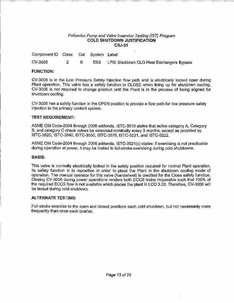
Palisades Pump and Valve lnservice Testing (/ST) Program COLD SHUTDOWN JUSTIFICATION
CSJ-31
Component ID Class Cat System Label
CV-3006 2 B ESS LPSI Shutdown CLG Heat Exchangers Bypass
FUNCTION:
CV-3006 is in the Low Pressure Safety Injection flow path and is electrically locked open during Plant operation. This valve has a safety function to CLOSE when lining up for shutdown cooling. CV-3006 is not required to change position until the Plant is in the process of being aligned for shutdown cooling.
CV-3006 has a safety function in the OPEN position to provide a flow path for low pressure safety injection to the primary coolant system.
TEST REQUIREMENT:
ASME OM Code-2004 through 2006 addenda, ISTC-3510 states that active category A. Category B, and category C check valves be exercised nominally every 3 months, except as provided by ISTC-3520, ISTC-3540, ISTC-3550, ISTC-3570, ISTC-5221, and ISTC-5222.
ASME OM Code-2004 through 2006 addenda, ISTC-3521(c) states: if exercising is not practicable during operation at power, it may be limited to full-stroke exercising during cold shutdowns.
BASIS:
This valve is normally electrically locked in the safety position required for normal Plant operation. Its safety function is to reposition in order to place the Plant .in the shutdown cooling mode of operation. The manual operator for this valve (handwheel) is credited for the Close safety function. Closing CV-3006 during power operations renders both ECCS trains inoperable such that 100% of the required ECCS flow is not available which places the plant in LCO 3.03. Therefore, CV-3006 will be tested during cold shutdown.
ALTERNATE TESTING:
Full-stroke exercise to the open and closed positions each cold shutdown, but not necessarily more frequently than once each quarter.
Page 13 of 29

Palisades Pump and Valve Jnservice Testing (/ST) Program COLD SHUTDOWN JUSTIFICATION
CSJ-33
Component ID Class Cat System Label
CV-1359 3 B SWS Non-Critical Service Water Isolation
FUNCTION:
This valve has a safety function to CLOSE and isolate the non-essential service water header on receipt of a Safety Injection Signal or Containment High Pressure signal. This will ensure that sufficient service water cooling capacity will be available to mitigate the consequences of an accident.
This valve has NO safety function in the OPEN position. It provides SWS flow to only non-critical loads.
TEST REQUIREMENT:
ASME OMa-2005 ISTC-3521(c); if exercising is not practicable during operation at power, it may be limited to full-stroke exercising during cold shutdowns.
BASIS:
Shutting of this valve during Plant operation will isolate cooling water to components that are essential for the operation of the non-nuclear portion of the Plant. The components served include the condensate pumps, the generator cooler, the exciter cooler, and the feedwater pump turbine heat exchanger. This valve will be full-stroke exercised during cold shutdowns when these components are out of service.
ALTERNATE TESTING:
Full-stroke exercise to the closed position each cold shutdown, but not necessarily more frequently than once each quarter. Test position indication at least once every two years.
Page 14 of 29

Palisades Pump and V;;ilve lnservice Te~ting (/ST) Program COLD SHU'f DOWN JUSTIFICATiON
CSJ-34
Component ID Class Cat. S:ystem Label
CV-.2001 1 B eve Letdown Stop
CV-2002 1 B eve Letdown Orifice Bypass Valve
CV-2003 1 B eve Letdown Orifice Stop Valve
cv-2004 1 B eve Letdown Orifice Stop Valve
CV-'2005 1 B eve Letdown OrifiCe Stop Valve
FUNCTION:
These valves have NO safety function in the OPEN position. The letdown function of the CVC System is not relied upon for any accident ·scenario.
These valves have an ACTIVE safety function in the CLOSED position to .provitje Reactor Coolant Pressure Boundary integrity in the event of a passive faih.ffe in the charging piping downstream of this valve~
CV-2001 does not have a safety function In either the OPEN or CLOSED position. Its testing is supplemental
TEST REQUIREMENT:
ASME OM-2005 ISTC-3521(c); if.exercising Is not practicable during operation at power, it may be limited to full'."stroke exercising dLiririg cold shutdowns.
BASIS:
Open and closing of these Valves will interrupt normal letdown flow and may result in pressurizer
pressure and level transients.
Open and closing of these valves rriay cause dose rates in the charging pump area to increase;
ALTERNATE TESTING:
Exercise during cold shutdowns, but not necessarily more frequently than once everj 3 months (quarterly). The testing for CV-2001 is supplemental testing. CV-'2001 does not have a safety
function in the open or closed direction.
Page 15 of 29

Palisades Purnp. an(/ Va/Ve lns~rvic~ Testing (/ST) Progr~m COLD SHUTDOWN JUSTIFICATION
CSJ•34 Position Verification (Remote Position Indication) Testing is performed each refueling outage and at least once every two years.
Page 16 of 29

Palisades Pump and Valve /nservice Testing (/ST) Program COLD SHUTDOWN JUSTIFICATION
CSJ-35
Component ID Class Cat. System Label
CV-2111 2 B eve Charging Line Containment lsol (MZ-45)
FUNCTION:
CV-2111 does NOT perform a safety function in the OPEN position.
CV-2111 performs a safety function in the CLOSED position. This air operated valve is a containment isolation valve for penetration 45, but it does not receive an automatic closure signal because the charging system operates during all Emergency Operations and Shutdown modes.
TEST REQUIREMENT:
-ASME OM-2005 ISTC-3521(c); if exercising is not practicable during operation at power, it may be limited to full-stroke exercising during cold shutdowns.
BASIS:
Open and closing of this valve will interrupt normal charging flow and may result in pressurizer pressure and level transients.
ALTERNATE TESTING:
Exercise during cold shutdowns, but not necessarily more frequently than once every 3 months (quarterly).
Position Verification (Remote Position Indication) Testing is performed each refueling outage and at least once every two years.
Page 17 of 29

Palisades Pump and Valve lnservice Testing (IS7) Program COLD SHUTDOWN JUSTIFICATION
Component ID Class Cat.
M0-2160 2 B
FUNCTION:
CSJ-36
System
eve
Label
SIRWT T-58 OUTLET TO CHARGING PP P-55A,B,C
This valve has NO safety function in the OPEN position.
This valve has an ACTIVE safety function in the CLOSED position to prevent diversion of SIRW Tank inventory from the Safety Injection Systems during a design basis accident.
TEST REQUIREMENT:
ASME OM-2005 ISTC-3521 (c); if exercising is not practicable during operation at power, it may be limited to full-stroke exercising during cold shutdowns.
BASIS:
Opening M0-2160 will cause boration of the PCS through the addition of borated water from the SIRW tank. This could result in a reactivity change.
ALTERNATE TESTING
Exercise during cold shutdowns, but not necessarily more frequently than once every 3 months (quarterly).
Position Verification (Remote Position Indication) Testing is performed each refueling outage and at least once every two years.
Page 18 of 29
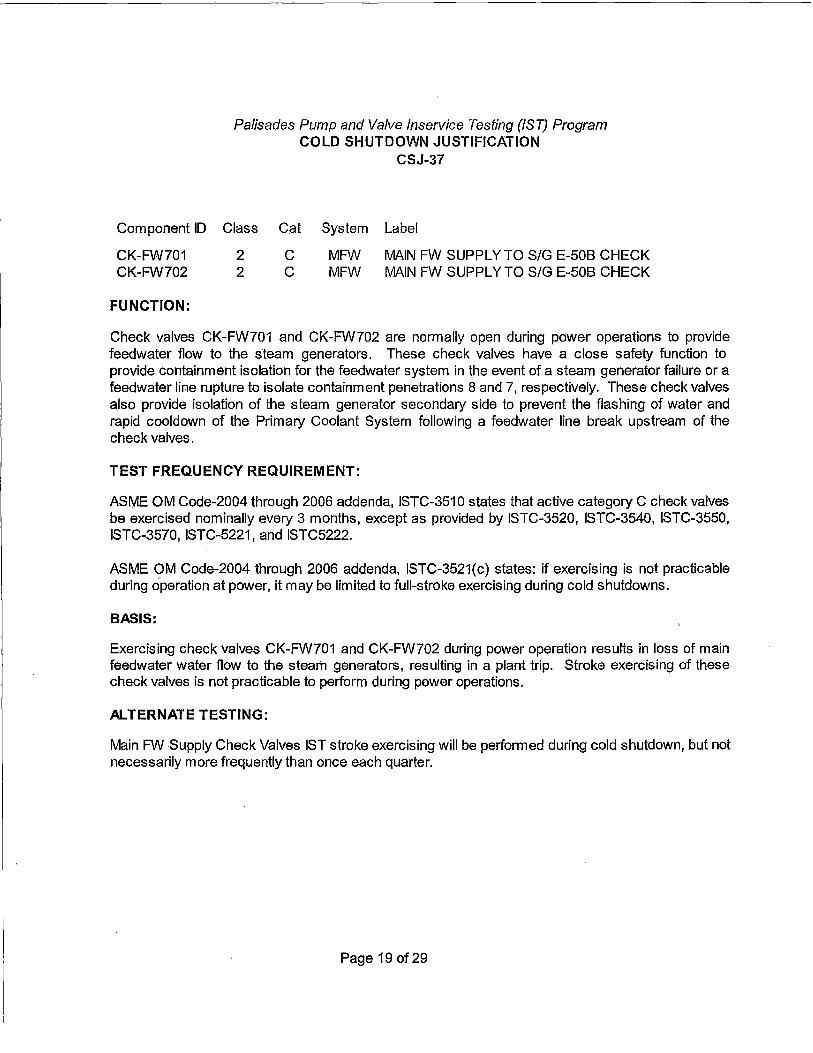
Palisades Pump and Valve lnservice Testing (/ST) Program COLD SHUTDOWN JUSTIFICATION
CSJ-37
Component ID Class Cat System Label
CK-FW701 CK-FW702
FUNCTION:
2 2
c c
MFW MFW
MAIN FW SUPPLYTO S/G E-508 CHECK MAIN FW SUPPLY TO SIG E-508 CHECK
Check valves CK-FW701 and CK-FW702 are normally open during power operations to provide feedwater flow to the steam generators. These check valves have a close safety function to provide containment isolation for the feedwater system in the event of a steam generator failure or a feedwater line rupture to isolate containment penetrations 8 and 7, respectively. These check valves also provide isolation of the steam generator secondary side to prevent the flashing of water and rapid cooldown of the Primary Coolant System following a feedwater line break upstream of the check valves.
TEST FREQUENCY REQUIREMENT:
ASME OM Code-2004 through 2006 addenda, ISTC-3510 states that active category C check valves be exercised nominally every 3 months, except as provided by ISTC-3520, ISTC-3540, ISTC-3550, ISTC-3570, ISTC-5221, and ISTC5222.
ASME OM Code-2004 through 2006 addenda, ISTC-3521(c) states: if exercising is not practicable during operation at power, it may be limited to full-stroke exercising during cold shutdowns.
BASIS:
Exercising check valves CK-FW701 and CK-FW702 during power operation results in loss of main feedwater water flow to the steam generators, resulting in a plant trip. Stroke exercising of these check valves is not practicable to perform during power operations.
ALTERNATE TESTING:
Main FW Supply Check Valves IST stroke exercising will be performed during cold shutdown, but not necessarily more frequently than once each quarter.
Page 19 of 29

Palisades Pump and Valve lnseNice Testing (/ST) Program COLD SHUTDOWN JUSTIFICATION
CSJ-38
Component ID Class Cat System Label
CK-ES3201 CK-ES3192
FUNCTION:
2 2
c c
ESS ESS
LOW PRESS PUMP P-67A DISCHARGE CHECK LOW PRESS PUMP P-678 DISCHARGE CHECK
Check valves CK-ES3201 and CK-ES3192 have an open safety function to provide low pressure safety injection (LPS I) flow to the primary coolant system following a safety injection actuation signal (SIAS). These check valves have a close safety function if the associated LPSI pump is idle to prevent diversion of flow from the operating LPSI pump in the opposite train.
TEST FREQUENCY REQUIREMENT:
ASME OM Code-2004 through 2006 addenda, ISTC-3510 states that active category C check valves be exercised nominally every 3 months, except as provided by ISTC-3520, ISTC-3540, ISTC-3550, ISTC-3570, ISTC-5221, and ISTC5222.
ASME OM Code-2004 through 2006 addenda, ISTC-3521(c) states: if exercising is not practicable during operation at power, it may be limited to full-stroke exercising during cold shutdowns.
BASIS:
Exercising check valves CK-ES3201 and CK-ES3192 during power operation is not feasible since the check valves are downstream of the minimum recirculation flow line. There are no other flow paths downstream of the minimum recirculation Hne available for flow testing, without making other systems inoperable, with the primary coolant system (PCS) pressurized. Stroke exercising of these check valves is not practicable to perform during power operations.
ALTERNATE TESTING:
LPSI pump discharge check valves IST stroke exercising will be performed during cold shutdown, but not necessarily more frequently than once each quarter, when the PCS is depressurized.
Page 20of29

Paiisades Pump and Valve lnservice Testing (/ST) Program COLD SHUTDOWN JUSTIFICATION
CSJ-39
Con'rponent ID Class. · Cat System Label
CK-ES3103 CK-ES3118 CK-ES3133 CK"'ES3148
FUNCTION:
1 1 1 1
A/C NC A!C A/C
ES$. ESS ESS ESS
LOW PRESSURE INJECTION CHECK VALVE LOW PRESSURE INJECTION CHECK VALVE !-OW PRESSURE INJECTION CHECK VAL~ LOW PRESSURE INJECTION CHECK VALVE
Check Valves CK~ES3103, CK-ES3118, CK-ES3133 and CK-ES3148 have an open safety function to provide low pressure safety injecticm (LPSI) flow to the primary c.oolant system following a safety injection actuation signal (SIAS). The.se check valves must close to prevent a diversion of high press1.1re scitety !njection flow, This check valve is a primary coolant system (PCS} pressure isolc:ition v~ilve (PIV). PNs have a safety functi~m to isolc;ite high PCS pressure from an attached low pressure system.
TEST FREQUENCY REQUIREMENT:
ASME OM Code;..2004 through 2006 addenda, ISTC-3510 states that active category A and category c check valves be exercised nominally every 3 months, except as provided by ISTC.;3520, ISTC-3540, ISTC-3550, ISTc.:3570, ISTC-5221, and ISTC5222.
ASME OM Code-2004 through 2006 addenda, ISTC-,3521(c) states: if ex~rcising is not practicable during operation at power, it may be limited to fuli-stroke exercising during cold shutdowns.
BASIS:
Exercising check valve.s CK-ES3103, CK-ES3118, CK•ES3133 and CK-ES3148 during power operation is not feasible since the check valves are downstream of the minimum recirculation flow line. There are no other flow paths downstream of the minimum recirculation line available for flow testirJQ, without making other systems· inoperable, with the primary coofant system (PCS) pressurized .. Stroke exercising of these check valves is not practicable to perform during power operations.
ALTERNATE TESTING:
LPSI pump injection check valves IST stroke exercising will be performed .during cold shutdown, but not necessarily more frequently than once each quarter, when the PCS is depressurized.
Page 21 of 29

Palisades Pump and Valve lnservice Testing (/ST) Program REFUELING OUT AGE JUSTIFICATION
ROJ-01
Component ID Class Cat. System Description Drawing
CK-ES3410 1 c ESS HPSI Hot Leg Injection Check Valve (M201-1/C-3)
FUNCTION: (Open) This check valve must open to provide a flow path for high pressure safety injection (HPSI) to the primary coolant system (PCS) hot leg. The hot leg injection flow path is established in order to prevent excessive buildup of boron precipitate due to boiloff in the core. Excessive precipitate could interfere with core cooling.
TEST REQUIREMENT: ASME 0Mb-2006 ISTC-3522(c); If exercising is not practicable during operation at power and cold shutdowns, it shall be performed during refueling outages.
BASIS: Open-stroke testing during hot plant conditions is not practical based on a full flow test path not being available with the plant above cold shutdown conditions. Also due to the HPSI Pump head being lower than Primary Coolant System (PCS) system pressure, and nozzle thermal shock considerations while testing using the Hot Leg Injection flow path is not possible.
Full flow testing cannot be performed during cold shutdowns while the reactor head is installed due to the potential for primary system over pressurization. Operation of the HPSI Pumps is prohibited by Technical Specification with the PCS temperature <300'F and theReactor Vessel Head in place.
ALTERNATE TESTING: CK-ES3410 will be open-stroke exercised during each refueling outage. System flow and pressure is recorded and trended to monitor the valve for degradation.
Page 22 of 29

Palisades Pump and Valve lnservice Testing (/ST) Program REFUELING OUTAGE JUSTIFICATION
ROJ-02
c·omponent ID Class Cat. System Description Drawing
CK-ES3104 1 NC ESS High Pressure Injection Check Valve (M203-2/G-8) CK-ES3119 1 NC ESS High Pressure Injection Check Valve (M203-2/F-8) CK-ES3134 1 NC ESS High Pressure Injection Check Valve (M203-2/D-8) CK-ES3149 1 NC ESS High Pressure Injection Check Valve (M203-2/B-8)
FUNCTION: (Open) These check valves must open to provide a flow path for emergency core cooling from the high pressure safety injection (HPSI) pump to the reactor coolant system. HPSI flow is initiated by a Safety Injection Signal (SIS).
(Closed) These check valves must close to prevent a diversion of flow from Train 2 of high pressure safety injection and/or LPSI if the Train 1 HPSI Pump is idle. This check valve is also a primary coolant system (PCS) pressure isolation valve (PIV). PIVs have a safety function to isolate high PCS pressure from an attached low pressure system. This is required to prevent failure of the pressure boundary of the low pressure system resulting in a loss of coolant accident.
TEST REQUIREMENT: ASME OMb-2006 ISTC-3522(c); If exercising is not practicable during operation at power and cold shutdowns, it shall be performed during refueling outages.
BASIS: Full-stroke (Open) testing during normal operation is impractical because the discharge pressure of the HPSI pumps is insufficient to overcome PCS pressure at normal operating conditions. Testing during normal operations is also not prudent due to the risk of damage to the valve seats and nozzles resulting from the thermal stresses set up when injecting cold water across a hot valve seat. In addition full-stroke exercising these valves would require injecting highly borated water into the Primary Coolant System (PCS). This would rapidly reduce reactivity resulting in a power transient (reduction) and possibly a pressure/temperature transient.
Full flow testing cannot be performed during cold shutdowns while the reactor head is installed due to the potential for primary system over pressurization. Operation of the HPSI pumps is prohibited by Technical Specification with the PCS temperature <300 F and the reactor vessel head in place. Full-stroke testing can only be performed during a reactor refueling when the reactor vessel head is removed providing an adequate surge volume for the pumps.
Closed testing can be performed in cold shutdowns, however, the plant may not be in a cold shutdown condition during a fuel cycle and therefore the testing will be performed during refueling outages.
ALTERNATE TESTING: During refueling outages (reactor vessel head removed), these check valves will be full-stroke (Open and Closed) exercise tested.
Page 23 of 29

Palisades Pump and Valve lnservice Testing (/ST) Program REFUELING OUTAGE JUSTIFICATION
ROJ-03
Component ID Class Cat. System Description Drawing
CK-ES3250 1 c ESS High Pressure Injection Check Valve (M203-2/G-8) CK-ES3251 1 c ESS High Pressure Injection Check Valve (M203-2/E-8) CK-ES3252 1 c ESS High Pressure Injection Check Valve (M203-2/C-8) CK-ES3253 1 c ESS High Pressure Injection Check Valve (M203-2/B-8)
FUNCTION: (Open) These check valves must open to provide a flow path for emergency core cooling from the high pressure safety injection (HPSI) pump to the primary coolant system (PCS}. HPSI flow is initiated by a Safety Injection Signal (SIS).
(Closed) These check valves must.close to prevent a diversion offlow from Train 1 of high pressure safety injection and/orlow pressure safety injection (LPS I) if the Train 2 HPS I Pump is idle. This check valve is a primary coolant system (PCS) boundary valve; however, it is not a pressure isolation valve (PIV). PIVs have a safety function to isolate high PCS pressure from an attached low pressure system.
TEST REQUIREMENT: ASME OMb-2006 ISTC-3522(c); If exercising is not practicable during operation at power and cold shutdowns, it shall be performed during refueling outages.
BASIS: Full-stroke (Open) testing during normal operation is impractical because the discharge pressure of the HPSI pumps is insufficient to overcome PCS pressure at normal operating conditions. Testing during normal operations is also not prudent due to the risk of damage to the valve seats and nozzles resulting from the thermal stresses set up when injecting cold water across a hot valve seat. In addition full-stroke exercising these valves would require injecting highly borated water into the Primary Coolant System (PCS). This would rapidly reduce reactivity resulting in a power transient (reduction) and possibly a pressure/temperature transient.
Full flow testing cannot be performed during cold shutdowns while the reactor head is installed due to the potential for primary system over pressurization. Operation of the HPSI pumps is prohibited by Technical Specification with the PCS temperature <300'F and the reactor vessel head in place. Full-stroke testing can only be performed during a reactor refueling when the reactor vessel head is removed providing an adequate surge volume for the pumps.
Closed testing can be performed in cold shutdowns, however, the plant may not be in a cold shutdown condition during a fuel cycle and therefore the testing will be performed during refueling outages.
ALTERNATE TESTING: During refueling outages (reactor vessel head removed), these check valves will be full-stroke (Open and Closed) exercise tested.
Page 24of29

Palisades Pump and Valve lnservice Testing (/ST) Program REFUELING OUT AGE JUSTIFICATION
ROJ-04
Component ID Class Cat. System Description
CK-ES3408 CK-ES3409
FUNCTION:
1 1
c c
ESS ESS
Hot Leg Injection Check Valve Hot Leg Injection Check Valve
Drawing
(M203-2/E-5) (M203-2/E-5)
(Open) These check valves must open to provide a flow path for high pressure safety injection (HPSI) to the primary coolant system (PCS) hot leg. The hot leg injection flow path is established in order to prevent excessive buildup of boron precipitate due to boiloff in the core. Excessive precipitate could interfere with core cooling.
(Closed) These check valves must close to prevent diversion of flow if the redundant train of high pressure safety injection is idle. This check valve must also close to maintain the reactor c;oolant pressure boundary (RCPB).
TEST REQUIREMENT: ASME OMb-2006 ISTC:-3522(c); If exercising is not practicable during operation at power and cold shutdowns, it shall be performed during refueling outages.
BASIS: Full-stroke (Open and Closed) exercise testing of these valves during normal operation, including cold shutdowns is impractical. Exercising these valves requires injecting Safety Injection and Refueling Water (SIRW) tank water into the PCS. This test path cannot be used during normal power operations, since the PCS is at a greater pressure than the HPSI pump discharge. Also, the injection of the highly borated SIRW tank water into the PCS would result in a reactivity change power transient (reduction) and possibly a pressure/temperature transient. Testing at any Plant condition greater than cold shutdown may result in thermal shock to the injection nozzles.
Full flow testing cannot be performed during cold shutdowns while the reactor head is installed due to the potential for primary system over pressurization. Operation of the HPSI pumps is prohibited by Technical Specification with the PCS temperature <300 F and the reactor vessel head in place. Full-stroke testing can only be performed during a reactor refueling when the reactor vessel head is removed providing an adequate surge volume for the pumps.
ALTERNATE TESTING: During refueling outages (reactor vessel head removed), these check valves will be full-stroke(Open and Closed) exercise tested.
Page 25 of 29

Component ID
CK-SW401 CK-SW402 CK-SW403
FUNCTION:
Palisades Pump and Valve lnservice Testing (/ST) Program REFUELING OUTAGE JUSTIFICATION
ROJ-05
Class Cat. System Description
3 c sws Service Water Pump P-7ADischarge Check 3 c sws Service Water Pump P-78 Discharge Check 3 c ·sws Service Water Pump P-7C Discharge Check
Drawing
(M213/F-4) (M213/F-3) (M213/F-2)
(Open) These check valves provide service water (SW) flow from pump to the SW discharge header. The SW pumps start automatically upon receipt of a Safety Injection Signal (SIS) as well as on low SW discharge header pressure. These valves must pass the required design flow rate of pump.
TEST REQUIREMENT: ASME OMb-2006 ISTC-3522(c); If exercising is not practicable during operation at power and cold shutdowns, it shall be performed during refueling outages.
BASIS: Full flow (Open) exercising these check valves to the open position requires knowledge of the individual pump flow rates. Individual pump units do not have installed flow indicators capable of recording high SW flow rates and piping configuration will not allow an installation of indicators which meet Code requirements. Therefore SW pump full flow testing can only be accomplished during refueling outages when SW flow can be removed from other components and the Containment service water flow indicator used to determine individual SW pump flows.
ALTERNATIVE TESTING: These check valves will be full flow (Open) tested each refueling outage during performance of the SW pumps comprehensive test R0-144, "Comprehensive Pump Test Procedure Service Water Pumps P-7A, P-78 and P-7C."
Page 26 of 29

Palisades Pump and Valve lnservice Testing (/ST) Program REFUELING OUTAGE JUSTIFICATION
ROJ-06
Component ID Class Cat. System Description Drawing
CK-ES3102 1 A/C ESS Safety Injection Tank T-82A Check Valve (M203-1/D-7) CK-ES3117 1 A/C ESS Safety Injection Tank T-828 Check Valve (M203-1/D-5) CK-ES3132 1 A/C ESS Safety Injection Tank T-82C Check Valve (M203-1/D-3) CK-ES3147 1 A/C ESS Safety Injection Tank T-820 Check Valve (M203-1/D-2)
FUNCTION: (Open) These check valve opens to provide a flow path from the Emergency Core Cooling System (ECCS) safety injection (SI) tank to the primary coolant system (PCS). This valve is required to operate when primary pressure decreases below that of the safety injection accumulators.
TEST REQUIREMENT: ASME OMb-2006 ISTC-3522( c ); If exercising is not practicable during operation at power and cold shutdowns, it shall be performed during refueling outages.
BASIS: Full-stroke (Open) exercise testing of these valves during normal operation is impractical. The subject valves cannot be full-stroke tested open during power operations or hot standby when PCS operating conditions are at 2060 psia and 532'F. The SI Tanks provide an available driving head of 258 psia which is not sufficient to overcome a PCS pressure of 2060 psia. Therefore, it is necessary to cool down and depressurize the PCS to conduct a stroke test of these valves.
Stroke testing these valves at a normal/forced cold shutdown is also impractical due to the fact that the SI Tanks contain highly borated water. Injection of the SI Tanks to the PCS at a time other than refueling is impractical due to excessive dilution required to restart the plant from cold shutdown.
ALTERNATE TESTING: These check valves will be full-stroke (Open) exercise tested each refueling. outage when the reactor vessel closure head is removed.
Page 27of29

Component ID
CK-ES3101 CK-ES3116
Palisades Pump and Valve lnservice Testing (/ST) Program REFUELING OUT AGE JUSTIFICATION
ROJ-07
Class Cat. System Description
1 NC ESS PCS Loop Check Valve (Loop 1A) 1 NC ESS PCS Loop Check Valve (Loop 1 B)
Drawing
(M203-1/B-8) (M203-1/B-7)
CK-ES3131 1 NC ESS PCS Loop Check Valve (Loop 2A) ( M203-1 /B-7) CK-ES3146 1 NC ESS PCS Loop Check Valve (Loop 28) (M203-1/B-7)
FUNCTION: (Open) These check valves open to provide a flow path from the Emergency Core Cooling System (ECCS) safety injection (SI) tank and the safety injection pumps to the primary coolant system (PCS). These valves are required to operate when primary pressure decreases below that of the safety injection accumulators.
TEST REQUIREMENT: ASME OMb-2006 ISTC-3522(c); If exercising is not practicable during operation at power and cold shutdowns, it shall be performed during refueling outages.
BASIS: Full-stroke (Open) exercise testing of these valves during normal operation, including cold shutdowns is impractical. The subject valves cannot be full-stroke tested during power operations or hot standby when Primary Coolant System (PCS) operating conditions are at 2060 psia and 532°F. The SI Tanks provide an available driving head of 258 psia which is not sufficient to overcome a PCS pressure of 2060 psia. Additionally, none of the Safety Injection or Charging Pumps provide sufficient head and flow to perform an acceptable test. Therefore, it is necessary to cool down and depressurize the PCS to conduct a stroke test of these valves.
ALTERNATE TESTING: Palisades will full-stroke (Open) exercise these check valves each refueling outage.
Page 28of29

Component ID
CK-ES3208 CK-ES3220 CK-ES3230
FUNCTION:
Palisades Pump and Valve fnservice Testing {/ST) Program REFUELING OUTAGE JUSTIFICATION
ROJ-08
Class Cat. System Description
2 c ESS CllvlT Spray Pump P-54C Discharge Check Valve 2 c ESS CllvlT Spray Pump P-548 Discharge Check Valve 2 c ESS CllvlT Spray Pump P-54A Discharge Check Valve
Drawing
(M204-1/D-4) (M204-1/B-4) (M204-1/D-5)
(Open) These check valves must open to allow containment spray flow from the containment spray pump to the discharge header.
(Closed} These check valves must close to prevent diversion of flow if the associated containment spray pump is idle.
TEST REQUIREMENT: ASME OMb-2006 ISTC-3522(c); If exercising is not practicable during operation at power and cold shutdowns, it shall be performed during refueling outages.
BASIS: Full-stroke (Open and Closed) exercising the Containment Spray Pump discharge check valves by initiation of the Containment Spray System (CSS) and spraying down the containment, if the containment spray valves are used as the flow path, is not practicle. Large spray flow into containment would potentially result in equipment damage.
Use of the 1 inch recirculation line to the Safety Injection and Refueling Water (SIRW) tank is not practical for flow testing due to the small size of the recirculation line.
Use of the 6-indh shutdown cooling (SOC) HX discharge recirc to SIRW tank line while operating i~ not possible because it requires installation of the open end of a spectacle flange and presents an unmonitored leak path should an accident occur during pump/valve testing that requires recirculation of contaminated fluid from the containment sump. This alignment makes the entire containment spray system inoperable. This line is isolated by installation of a blind-flange during normal Plant operation.
ALTERNATE TESTING: Each check valve will be full-stroke (Open and Closed) exercised during refueling outages.
Page 29 of 29