panelmate power series transfer utility user’s guideiv panelmate power series transfer utility...
TRANSCRIPT

PanelMate Power SeriesTransfer UtilityUser’s Guide
&XWOHU�+DPPHU173 Heatherdown DriveWesterville, OH 43086-6166

The information contained in this manual is the property of Cutler-Hammer, Inc. Information in thismanual is subject to change without notice and does not represent a commitment on the part ofCutler-Hammer, Inc.
Any Cutler-Hammer software described in this manual is furnished under a license agreement. Thesoftware may be used or copied only in accordance with the terms of the agreement. It is against thelaw to copy the software on any medium except as specifically allowed in the agreement. No part ofthis manual may be reproduced or transmitted in any form or by any means, electronic, mechanical,photocopying, recording or otherwise, without prior written permission of Cutler-Hammer, Inc.
RESTRICTED RIGHTS LEGEND
Use, duplication, or disclosure by the Government is subject to restrictions set forth in paragraph(b)(3)(B) of the Rights in Technical Data and Computer Software clause of DAR 7-104.9(a).Contractor/Manufacturer is Cutler-Hammer, P.O. Box 6166, Westerville, OH 43086-6166.
TRADEMARKS
Commercial names of products from other manufacturers or developers that appear in this manual areregistered or unregistered trademarks of those respective manufacturers or developers, which haveexpressed neither approval nor disapproval of Cutler-Hammer products.
PanelMate is a registered trademark of Cutler-Hammer, Inc.Microsoft and Windows are registered trademarks of Microsoft CorporationModbus is a registered trademark of Schneider Automation Inc.
Copyright Cutler-Hammer, Inc. 1999. All rights reserved.
P/N 01-00395-00

Table of Contents i
Table of ContentsPREFACE............................................................................................................................................... I
About This Manual........................................................................................................................... IIPurpose ......................................................................................................................................... IIWhat’s Inside................................................................................................................................ II
Support Services..............................................................................................................................III
CHAPTER 1: INTRODUCTION .........................................................................................................1
Transfer Utility Overview .................................................................................................................2Installing the PanelMate Transfer Software ......................................................................................2About PanelMate Transfer ................................................................................................................3Transfer Mode...................................................................................................................................3
PanelMate Power Series ................................................................................................................3PanelMate Power Series Transfer Steps............................................................................................4
CHAPATER 2: PANELMATE TRANSFER SOFTWARE...............................................................5
PanelMate Power Series Memory .....................................................................................................6PanelMate Transfer ...........................................................................................................................7PanelMate Power Series Network Transfers .....................................................................................8PanelMate (V211) Transfer...............................................................................................................8PanelMate Series V211 Drivers List .................................................................................................9Operation List Box..........................................................................................................................11System/Configuration Information..................................................................................................12Operation Status ..............................................................................................................................13PanelMate Transfer - Configuration Tab ........................................................................................14
Download Configuration .............................................................................................................15Upload Configuration ..................................................................................................................16
PanelMate Transfer - Executive Tab...............................................................................................17PanelMate Transfer - Driver Tab ....................................................................................................18PanelMate Transfer - Options Tab ..................................................................................................19
Option Diskette Verification........................................................................................................20PanelMate Transfer - System Info. Tab...........................................................................................21PanelMate Transfer - Port Params. Tab ..........................................................................................23
5136-SD/DH................................................................................................................................255136-SD/DH+..............................................................................................................................265136-SD/REM I/O.......................................................................................................................27AB Interchange............................................................................................................................28AB Interchange Rem I/O .............................................................................................................28AB RSLinx ..................................................................................................................................29AB RSLinx Rem I/O....................................................................................................................29Modicon Modbus Plus.................................................................................................................30

ii PanelMate Power Series Transfer Utility User’s Guide
NETWORK TRANSFER TROUBLESHOOTING.......................................................................... 31
Network Transfer Troubleshooting Tips ........................................................................................ 32Network Transfer Errors ................................................................................................................ 32
1784-KT or 1784-PCMK Data Highway Plus Errors ................................................................. 325136-SD Data Highway Plus Errors ........................................................................................... 33KF2 Module Data Highway Plus Errors ..................................................................................... 341784-KT, 1784-PCMK, or 5136-SD Remote I/O Errors............................................................ 35Modbus Plus Errors .................................................................................................................... 36Transfer Problems....................................................................................................................... 38Installing Serial Drivers ...............................................................................................................39
INDEX .................................................................................................................................................. 41

Preface I
PrefaceWelcome to the PanelMate Power Series Transfer Utility User’s Guide. This chapter describes thecontents of this manual and provides information on Support Services.

II PanelMate Power Series Transfer Utility User’s Guide
About This Manual
Purpose
This manual focuses on describing the features of the PanelMate Power Series Transfer Utility.
What’s Inside
This manual is organized in the following way:
Preface
Chapter 1: Introduction
Chapter 2: PanelMate Transfer Software
Chapter 3: Network Transfer Troubleshooting
Index

Preface III
Support Services
It is Cutler-Hammer’s goal to ensure your greatest possible satisfaction with the operation of ourproducts. We are dedicated to providing fast, friendly, and accurate assistance. That is why we offeryou so many ways to get the support you need. Whether it’s by phone, fax, modem, or mail, you canaccess Cutler-Hammer support information 24 hours a day, seven days a week. Our wide range ofservices include:
Technical Support 1-800-809-2772
If you are in the U.S. or Canada, you can take advantage of our toll-free line for technical assistancewith hardware and software product selection, system design and installation, and system debuggingand diagnostics. Technical support engineers are available for calls during regular business hours(8 am - 5:30 pm EST) by calling 1-800-809-2772. International calls can be made to either the TechLine at 1-800-809-2772 (toll call) or the Cutler-Hammer main business line at 614-882-3282.
Emergency Technical Support 1-800-809-2772
Because machines do not run on a nine-to-five schedule, we offer emergency after-hours technicalsupport. A technical support engineer can be paged for emergencies involving plant down situations orsafety issues. Emergency support calls are automatically routed directly to our answering serviceafter-hours (5:30 pm - 8 am EST) and weekends. For emergency technical support, call1-800-809-2772.
Note that the Emergency Technical Support phone number does not currently support product repairsor shipping outside normal business hours.
Technical Support Fax 614-882-0417
You can also contact our technical support engineers by faxing your support requests directly to theAdvanced Product Support Center (APSC) located in Westerville, Ohio at 614-882-0417.
Information Fax-Back Service 614-899-5323
The latest Cutler-Hammer product information, specifications, technical notes and company news isavailable to you via fax through our direct document request service at 614-899-5323. Using a touch-tone phone, you can select any of the info faxes from our automated product literature and technicaldocument library, punch in a fax number and receive the information immediately.
Website andE-mail Address
http://www.cutlerhammer.eaton.com/[email protected]
If you have Internet capabilities, you also have access to technical support via our website athttp://www.cutlerhammer.eaton.com/automation. The website includes technical notes, frequentlyasked questions, release notes, and other technical documentation. This direct technical supportconnection also offers you the ability to request assistance and exchange software files electronically.
Technical support messages and files can be sent to [email protected].

IV PanelMate Power Series Transfer Utility User’s Guide
Bulletin Board Service 614-899-5209
Parameters: 8 data bits, 1 stop bit, parity none, 9600-28.8K baud
If you have modem access, you can dial in directly to our electronic bulletin board service for the latestproduct and company information. File sharing, product software downloads and our user messageservice are just a few of the things you will find online at 614-899-5209.
Software Update Service 1-800-809-2772FAX 614-899-4141
We also offer you the opportunity to take advantage of software upgrades, advanced software notices,and special software promotions through our Software Update Service. When you register yoursoftware, you will receive one-year of free or reduced-price upgrades along with all the other benefitsof membership, including 48-hour shipping of software upgrades. Contact the Software Update Serviceat 1-800-809-2772 or fax 614-899-4141.
Repair and Upgrade Service 614-882-3282 ext. 7601FAX 614-882-3414
Our well-equipped Customer Service department is ready to assist you with repairs, upgrades, andspare parts services. If a situation arises where one of these services is needed, just call 614-882-3282x7601 or fax 614-882-3414.
Product Ordering Service 614-882-3282FAX 614-882-6532
Authorized Cutler-Hammer distributors may place product orders directly with our Order Processingdepartment by calling 614-882-3282 x406 or faxing 614-882-6532. For information on your localdistributor, call the Cutler-Hammer Tech Line.
Customer Support Center 1-800-356-1243
Authorized Cutler-Hammer distributors and Cutler-Hammer sales offices can get assistance for Cutler-Hammer standard and component product lines through the Customer Support Center. Call theCustomer Support Center for the following assistance:
1. Stock availability, proof of shipment, or to place an order.2. Expedite an existing order.3. Product assistance and product price information.4. Product returns other than warranty returns.
For information on your local distributor or sales office, call the Cutler-Hammer Tech Line at1-800-809-2772.
Correspondence Address Cutler-HammerP.O. Box 6166Westerville, OH 43086-6166
Shipping Address Cutler-Hammer173 Heatherdown DriveWesterville, OH 43081

Chapter 1: Introduction 1
Introduction
This chapter explains how to install your Transfer Software, how to place the PanelMate OperatorStation into Transfer Mode, and how to transfer the application. Specifically, this chapterincludes:
• Transfer Utility Overview
• Installing the PanelMate Transfer Software
• PanelMate Power Series Transfer Mode
• PanelMate Power Series Transfer Steps

2 PanelMate Power Series Transfer Utility User’s Guide
Transfer Utility OverviewThe PanelMate Power Series Transfer Utility is used to transfer information into the PanelMate unit.The target unit can be either a Cutler-Hammer PanelMate Power Series unit, or a PanelMate PowerSeries OEM model. The types of information that can be transferred include:
• Executive Firmware
• Network Drivers
• User Configurations
• PLC/Communications Drivers
• PanelMate Power Series Options (Requires an Options Diskette)
Note: PanelMate Power Series Transfer Utility versions below Version 4.1 do not supportdownloading of Cutler-Hammer PanelMate Power Series information to OEM units.
Installing the PanelMate Transfer SoftwareThe Software Kit contains either a CD-ROM or floppy disks. For CD-ROM installation instructions,refer to the Install.txt file on the CD-ROM. For floppy disk installation instructions, refer to theparagraphs that follow.
The PanelMate Transfer Software contains an installation program named Setup. Setup is on thediskette labeled “PanelMate Transfer Software Disk”.
To install the Transfer software on your hard disk, insert the diskette in your personal computer. If youare using Microsoft Windows, open the File Menu and select Run in the Program Manager. If you areusing Microsoft Windows 95, press the Start button and select Run.
In the Run dialog box, type:
drive:\SETUP
in the Command Line entry field, where drive is the letter of the floppy drive that contains the driverdiskette. Choose the OK button.
From the Setup program, select the directory for the transfer files.
Once the installation is complete, you will find the following files on your personal computer.
Filename Description
VCPXFER.EXE Transfer Software Executable file
VCPXFER.HLP Transfer Software Help file

Chapter 1: Introduction 3
About PanelMate TransferIf you select the About button on any of the dialog boxes displayed within the PanelMate Transfer, theAbout PanelMate Transfer dialog box will be displayed. The About PanelMate Transfer dialogbox will show the PanelMate Transfer version number and list the available memory, mathcoprocessor, and disk space information.
Transfer Mode
PanelMate Power SeriesThe PanelMate operator station must be in Transfer Mode before you can upload or download into theunit’s memory or install options.
To place the PanelMate operator station into the Transfer Mode you can:
• Manually place the PanelMate operator station into the Offline Mode then select the TransferMode.
• Remotely place the PanelMate operator station in Transfer Mode if you are using a supportedPLC communications network and have the Remote Transfer Option installed in the onlineunit.
If the PanelMate operator station cannot be placed into the Transfer Mode through the above normalmeans, it can be forced into the Transfer Mode in one of the following ways:
• To force a Keypad Unit with four control buttons into the Offline Mode, press the first andsecond control buttons simultaneously immediately on power up. Then select the Enter SerialTransfer Mode template or the Enter Network Transfer Mode template to enter the TransferMode.
• To force a Keypad Unit with five control buttons into the Offline Mode, press the second andthird control button simultaneously immediately on power up. You can then select the EnterSerial Transfer Mode template or the Enter Network Transfer Mode template to enter theTransfer Mode.
• To force a Touchscreen Unit into Offline Mode, press the lower right corner once thetouchscreen controller diagnostics are completed. (If you press the lower right corner on thetouchscreen before the touchscreen diagnostics are completed, you will receive an error.) Youcan then select the Enter Serial Transfer Mode template or the Enter Network Transfer Modetemplate to enter the Transfer Mode.
• To force a PanelMate operator station directly into the Transfer Mode, disconnect theElectronics Module from the monitor/keypad section of the unit.

4 PanelMate Power Series Transfer Utility User’s Guide
PanelMate Power Series Transfer Steps
The following steps are for new users who are unfamiliar with transfers to a PanelMate operatorstation. If nothing has been downloaded to your new PanelMate operator station, all the steps must becompleted for your application to run correctly. After completing the sequence of steps once, if youneed to change any of the items in the PanelMate operator station, you only need to perform the stepsnecessary to transfer that item (e.g., a different driver).
• Create a configuration. Note that the configuration must be exported before the configuration canbe downloaded to a PanelMate operator station.
• Configure the port parameters in the PanelMate Transfer - Port Params. Tab dialog box.
• Select the appropriate Executive Firmware and a network driver (if applicable) and add to theOperation list box in the PanelMate Transfer - Executive Tab dialog box.
• Select a driver and add the driver to the Operation list box in the PanelMate Transfer - DriverTab dialog box.
• If you purchased options, add the options to the Operation list box in the PanelMate Transfer -Options Tab dialog box.
• Add a configuration file to the Operation list box in the PanelMate Transfer - Configuration Tabdialog box.
• Place the PanelMate operator station in Transfer Mode.
• Connect the transfer cable and press the Start button in the PanelMate Transfer dialog box to beginthe transfer.

Chapter 2: PanelMate Transfer Software 5
PanelMate Transfer Software
This chapter overviews your PanelMate units memory areas, and describes each Transfer Softwaredialog box. Specifically, this chapter includes:
• PanelMate Power Series Network Transfers
• PanelMate Series (V2.11) Transfers
• Operation List Box
• System/Configuration Information
• Operation Status
• PanelMate Transfer Tabs

6 PanelMate Power Series Transfer Utility User’s Guide
PanelMate Power Series MemoryPanelMate operator station memory is segmented into three main areas: Executive Firmware memory,Driver memory, and User Configuration memory.
The PanelMate operator station also reserves memory to store options. Options can be downloaded atanytime while in Transfer Mode.
Executive Firmware Memory
The Executive Firmware is the base firmware of the PanelMate operator station A Network Driver letsyou download or upload over Allen-Bradley Data Highway, Data Highway Plus, Remote I/O, orModicon Modbus Plus networks. Without a network driver, you can only download or upload seriallywith the Executive Firmware.
The Executive Firmware and Network Driver (if desired) must be downloaded before you candownload configurations or PLC drivers.
The Executive Firmware contains the operating system and all software which comprise the onlinefunctionality. You can upgrade a PanelMate operator station by downloading new Executive Firmwarewithout having to ship the unit back to Cutler-Hammer. You can only download Executive Firmwareor Network Drivers, you cannot upload them.
Driver Memory
The Driver Memory is where the PLC or Host (Generic Protocol) drivers are stored. Before goingonline, you must download the PLC or Host Driver to match your User Configuration. PLC driversmust be downloaded after the Executive Firmware and PLC Network Driver, and beforeconfigurations. You can only download PLC drivers, you cannot upload them.
User Configuration Memory
User Configuration memory is where you store your configuration. The PanelMate operator stationmay have up to 100 pages of memory (50 pages for PanelMate Series 1500). Configurations must bedownloaded after the Executive Firmware, Network Driver, and PLC drivers. You can upload anddownload User Configurations.
Chapter 2: PanelMate Transfer Software 7
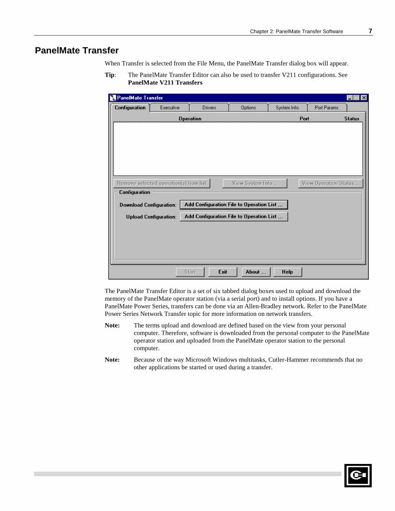
PanelMate TransferWhen Transfer is selected from the File Menu, the PanelMate Transfer dialog box will appear.
Tip: The PanelMate Transfer Editor can also be used to transfer V211 configurations. SeePanelMate V211 Transfers
The PanelMate Transfer Editor is a set of six tabbed dialog boxes used to upload and download thememory of the PanelMate operator station (via a serial port) and to install options. If you have aPanelMate Power Series, transfers can be done via an Allen-Bradley network. Refer to the PanelMatePower Series Network Transfer topic for more information on network transfers.
Note: The terms upload and download are defined based on the view from your personalcomputer. Therefore, software is downloaded from the personal computer to the PanelMateoperator station and uploaded from the PanelMate operator station to the personalcomputer.
Note: Because of the way Microsoft Windows multitasks, Cutler-Hammer recommends that noother applications be started or used during a transfer.

8 PanelMate Power Series Transfer Utility User’s Guide
PanelMate Power Series Network TransfersThe Transfer Utility supports transfers to an operator station via a supported PLC communicationsnetwork. Supported networks include:
• Allen Bradley Data Highway
• Allen-Bradley Data Highway Plus
• Allen Bradley Remote I/O Link
• Modicon Modbus Plus
To use remote network transfers, you must purchase and install:
• The Remote Transfer Option from Cutler-Hammer
• The appropriate communications card/device for your PC
Allen-Bradley networks
� A-B 1784-KT ISA card
� A-B 1784 PCMK ISA card
� SST (S-S Technologies) 5136-SD ISA card
� A-B KE/KF serial port module
Modicon Modbus Plus network
� Modicon SA85 card
• Allen-Bradley Interchange or RSLinx software if you are using Allen-Bradley devices.
Note: The SST card does not require additional purchased software.
PanelMate (V2.11) TransferFor non-Power Series PanelMate units: to download PanelMate V2.11 Executive Firmware or driversto a PanelMate Series 2000, PanelMate Series 3000, or PanelMate Series 4000, you must make thefollowing changes to the pmconfig.ini file.
Note: <path> is the file’s path on the personal computer.
1. In the [Executive Firmware List] section, add the following line:
seg1 = <path>\V2_110_1.exf
This line will allow the V211Executive Firmware to be selected in the PanelMate Transfer -Executive Tab dialog box.
2. In the [Executive Firmware List] section, add a line for each network driver to be downloaded.For example:
abdh=<path>\abdh.net
abrem=<path>\abrem.net
These lines will allow the V211network drivers to be selected in the PanelMate Transfer -Executive Tab dialog box. For a complete list of network drivers, refer to the PanelMateV2.11 drivers topic.

Chapter 2: PanelMate Transfer Software 9
3. In the [Drivers List] section, add a line for each communication driver to be downloaded. Forexample:
abdh=<path>\abdh.drv
abrem=<path>\abrem.drv
These lines will allow the V211communication drivers to be selected in the PanelMateTransfer - Driver Tab dialog box. For a complete list of communication drivers, refer to thePanelMate V211drivers topic.
Note: PanelMate V211 Executive Firmware and V211 communication drivers can only beloaded on a PanelMate Series 2000, PanelMate Series 3000, or PanelMate Series4000. If you try to load the V211 Executive Firmware or V211 communicationdrivers on a PanelMate Series 2000, PanelMate Series 3000, or PanelMate Series4000.
Note: Network transfers to PanelMate Series 2000, PanelMate Series 3000, and PanelMateSeries 4000 are supported.
PanelMate Series V211 Drivers ListNetwork Drivers
ABDH.NET Allen-Bradley Data Highway/Data Highway Plus
ABREM.NET Allen-Bradley Remote I/O
Communication Drivers
AB.DRV Allen-Bradley Serial
ABDH485.DRV Allen-Bradley Data Highway 485
ABDH.DRV Allen-Bradley Data Highway
ABDH.DRV Allen-Bradley Data Highway Plus
ABREM.DRV Allen-Bradley Remote I/O
CSITOL.DRV Custom Serial Interface
EATON.DRV Eaton
GE.DRV General Electric Peer-to-Peer
GE.DRV General Electric Master/Slave
GES90P.DRV General Electric Series 90 Point-to-Point
GES90.DRV General Electric Series 90 Network
GENERIC.DRV Generic Protocol
MITS.DRV Mitsubishi
MITSFX.DRV Mitsubishi FX Series
MODICON.DRV Modicon ASCII
MODRTU.DRV Modicon RTU
MRTUE.DRV Modicon RTU
MODA.DRV Modicon A Series
OMRON.DRV Omron Host Link

10 PanelMate Power Series Transfer Utility User’s Guide
RELIANCE.DRV Reliance
SIEMENS.DRV Siemens
SQUARED.DRV Square D
TI.DRV Texas Instruments
TIHL.DRV Texas Instruments Hostlink Peer-to-Peer
TIHL.DRV Texas Instruments Hostlink Master/Slave
TOSHT2.DRV Toshiba T2
WEST.DRV Westinghouse
Note: The CSI and Allen-Bradley Data Highway 485 drivers require option diskettes which arepurchased separately and must be installed in the PanelMate Series 2000, PanelMate Series3000 and PanelMate Series 4000 before the driver can be downloaded.
Note: The Modicon RTU Enhanced driver (MRTUE.DRV) used a 750 millisecond timeout versusthe Modicon RTU driver (MODRTU.DRV) which uses a 3 second timeout. (Timeout refersto the length of time the PanelMate operator station will wait to issue another request whena response was not received form the PLC.)

Chapter 2: PanelMate Transfer Software 11
Operation List BoxThe Operation list box is shown below.
Tip: If you double click on an operation in the Operation list box, the System/ConfigurationInformation dialog box will appear.
This list box contains the operations that are scheduled for execution. When an operation is added, it isadded to the end of the list if no operations are selected. If one or more operations are selected, the newoperations are added after the last selected operation.
For each operation in the list, the operation name, the communication port, and the operation status isdisplayed. Before the operation is started, the status message that will be displayed is PEND (pending).When you press the Start button, the first operation will be executed. When the operation is in progress,the status message that will be displayed is WORK. When the operation is completed, you will get astatus message of FAIL or PASS and the next operation in the list is selected and executed. The nextoperation is always executed, regardless of the success or failure of the previous operation. Thisprocess will continue until all of the operations in the list have been executed.

12 PanelMate Power Series Transfer Utility User’s Guide
There are three buttons associated with the Operation list box. The buttons are described below.
<Remove selected operation(s) from list>: Removes the selected operation from theOperation list box.
<View System Info>: Displays the System/Configuration Information dialog box with datafrom the currently selected operation.
<View Operation Status>: Displays the Operation Status dialog box with data from thecurrently selected operation.
System/Configuration InformationWhen the View System Info button is pressed, the System/Configuration Information dialog box willappear.
The System/Configuration Information dialog box displays the configuration information from thePanelMate operator station following the last operation and displays the version of the ExecutiveFirmware, options, and drivers loaded in the PanelMate operator station
The Save button allows you to save the System/Configuration Information to an ASCII text file.

Chapter 2: PanelMate Transfer Software 13
Operation StatusWhen the View Operation Status button is pressed, the Operation Status dialog box will appear.
The Operation Status dialog box contains a list box of errors and/or status messages associated with aparticular operation. Some of the errors or messages are about failed operations, while other errors ormessages contain helpful information about successful operations. A status (Fail, Pend, or Pass) of theoperation is also displayed.
The Save button allows you to save the errors or messages to an ASCII file.

14 PanelMate Power Series Transfer Utility User’s Guide
PanelMate Transfer - Configuration TabThe PanelMate Transfer - Configuration Tab dialog box is shown below.
Note: The above figure shows a PanelMate Power Series configuration in the Operation list box.
The PanelMate Transfer - Configuration Tab dialog box allows you to upload and downloadconfigurations. The configurations to be transferred will be displayed in the Operation list box. (Thefilename extension will vary depending on the PanelMate operator station) If you have a PanelMatePower Series, the configuration name and the filename used to export the configuration will bedisplayed in the Operation list box.
The fields in the PanelMate Transfer - Configuration Tab dialog box are described below:
<Remove selected operation(s) from list>: Removes the selected operation from the Operationlist box.
<View System Info>: Displays the System/Configuration Information dialog box with datafrom the currently selected operation.
<View Operation Status>: Displays the Operation Status dialog box with data from thecurrently selected operation.
Download Configuration: Allows you to download a configuration from the developmentcomputer to the PanelMate operator station The configuration will include system parameters,PLC connection information and display pages containing templates, elements, and static text.When you press the Add Configuration File to Operation List button, the DownloadConfiguration dialog box will appear.

Chapter 2: PanelMate Transfer Software 15
Note: Before downloading a configuration, you must export the configuration. Foradditional information on exporting configurations, refer to the Export topic in thePanelMate Power Series online help.
Upload Configuration: Allows you to upload a configuration from the PanelMate operatorstation to the development computer and store it. When you press the Add ConfigurationFile to Operation List button, the Upload Configuration dialog box will appear.
<Start>: Allows you to begin executing the first operation in the Operation list box.
<Exit>: Allows you to exit the PanelMate Transfer dialog box.
<About>: Displays the About PanelMate Transfer dialog box.
Download Configuration
Note: When downloading a PanelMate Series 1500 configuration to another model of thePanelMate Power Series, you must first convert the configuration to the appropriatePanelMate Power Series model using the configuration software.
When the Add Configuration File to Operation List button (next to the Download Configuration field)is pressed on the PanelMate Transfer - Configuration Tab dialog box, the Download Configurationdialog box will appear.
Note: In the above figure, the .XXX designates the filename extension. The filename extensionwill vary depending on the PanelMate operator station
The PanelMate operator station must be loaded with Executive Firmware and necessary drivers andoptions before it can receive a configuration.
In the Download Configuration dialog box, select the type of file you want to download, the name ofthe file to download, and the directory for your file.
When downloading a configuration containing an option, the transfer software will check to ensure thatthe option is installed. If the option is not installed, an error will be generated.
Note: If you are using Microsoft Windows for Workgroups, a Network button will appear underthe Help button.
16 PanelMate Power Series Transfer Utility User’s Guide
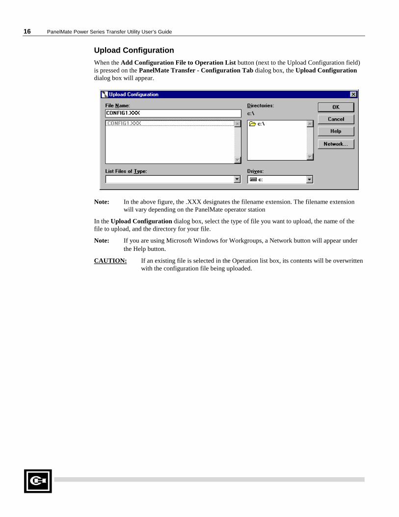
Upload Configuration
When the Add Configuration File to Operation List button (next to the Upload Configuration field)is pressed on the PanelMate Transfer - Configuration Tab dialog box, the Upload Configurationdialog box will appear.
Note: In the above figure, the .XXX designates the filename extension. The filename extensionwill vary depending on the PanelMate operator station
In the Upload Configuration dialog box, select the type of file you want to upload, the name of thefile to upload, and the directory for your file.
Note: If you are using Microsoft Windows for Workgroups, a Network button will appear underthe Help button.
CAUTION: If an existing file is selected in the Operation list box, its contents will be overwrittenwith the configuration file being uploaded.

Chapter 2: PanelMate Transfer Software 17
PanelMate Transfer - Executive TabNote: Once version 3.01 or higher Executive Firmware has been loaded onto your PanelMate
operator station, you will be unable to overwrite it with an older (version 3.0 or earlier) loadof Executive Firmware.
The PanelMate Transfer - Executive Tab dialog box is shown below.
The Executive tab allows you to download Executive Firmware and network drivers. An online systemmust contain Executive Firmware before it can execute a configuration.
Note: The Executive Firmware for a PanelMate Series 1500 is different from that used by otherPanelMate Power Series models (which all use the same firmware). Attempting to downloadPanelMate Series 1500 firmware to another PanelMate Power Series models (or vice versa)will generate an error.
Note: If you wish to download PanelMate Series V211 Executive Firmware, refer to thePanelMate Series (V211) Transfer topic.
The fields in the PanelMate Transfer - Executive Tab dialog box are described below:
<Remove selected operation(s) from list>: Removes the selected operation from theOperation list box.
<View System Info>: Displays the System/Configuration Information dialog box with datafrom the currently selected operation.
<View Operation Status>: Displays the Operation Status dialog box with data from thecurrently selected operation.

18 PanelMate Power Series Transfer Utility User’s Guide
Executive Firmware: Allows you to select and display the Executive Firmware to bedownloaded.
Note: All drivers previously loaded on the PanelMate operator station will be removed. You mustre-download the appropriate drivers after the Executive Firmware has been downloaded.
Network Driver: Allows you to select and display the network driver to be downloaded withthe Executive Firmware.
<Add to Operation List>: Adds the selected Executive Firmware and/or network driver tothe Operation list box to be downloaded.
<Start>: Allows you to begin executing the first operation in the Operation list box.
<Exit>: Allows you to exit the PanelMate Transfer dialog box.
<About>: Displays the About PanelMate Transfer dialog box.
PanelMate Transfer - Driver TabThe PanelMate Transfer - Driver Tab dialog box is shown below.
The Driver tab allows you to transfer a communication driver from the development computer to thePanelMate operator station. An online system must contain this driver to communicate to an outsidedevice, such as a PLC. The driver to be downloaded will be displayed in the Operation list box.

Chapter 2: PanelMate Transfer Software 19
The fields in the PanelMate Transfer - Driver Tab dialog box are described below:
<Remove selected operation(s) from list>: Removes the selected operation from theOperation list box.
<View System Info>: Displays the System/Configuration Information dialog box with datafrom the currently selected operation.
<View Operation Status>: Displays the Operation Status dialog box with data from thecurrently selected operation.
Communication Driver: Allows you to select and display the communication driver to bedownloaded.
<Add to Operation List>: Adds the selected driver to the Operation list box to bedownloaded.
<Start>: Allows you to begin executing the first operation in the Operation list box.
<Exit>: Allows you to exit the PanelMate Transfer dialog box.
<About>: Displays the About PanelMate Transfer dialog box.
PanelMate Transfer - Options TabThe PanelMate Transfer - Options Tab dialog box is shown below.

20 PanelMate Power Series Transfer Utility User’s Guide
The Options tab allows you to transfer an option from your development computer’s floppy disk to thePanelMate operator station. The option to be downloaded will be displayed in the Operation list box.
Note: When downloading a configuration containing an option, the transfer software will check toensure that the option is installed. If the option is not installed, an error will be generated.
The fields in the PanelMate Transfer - Options Tab dialog box are described below:
<Remove selected operation(s) from list>: Removes the selected operation from theOperation list box.
<View System Info>: Displays the System/Configuration Information dialog box with datafrom the currently selected operation.
<View Operation Status>: Displays the Operation Status dialog box with data from thecurrently selected operation.
Option Diskette: Displays the Option Diskette Verification dialog box when the Validatebutton is pressed.
Option Diskette Drive: Allows you to select the drive letter to locate your option diskette.Note that you should always press the Validate button before installing an option to check theremaining number of installations.
<Add to Operation List>: Adds the option to the Operation list box to be downloaded.
<Start>: Allows you to begin executing the first operation in the Operation list box.
<Exit>: Allows you to exit the PanelMate Transfer dialog box.
<About>: Displays the About PanelMate Transfer dialog box.
Option Diskette Verification
When the Validate button is pressed on the PanelMate Transfer - Options Tab dialog box, theOption Diskette Verification dialog box is shown below.
The Option Diskette Verification dialog box displays the option name and the number of remainingoption installations. If you do not have any remaining installations, call the Cutler-Hammer CustomerSupport Center for assistance.

Chapter 2: PanelMate Transfer Software 21
PanelMate Transfer - System Info. TabThe PanelMate Transfer - System Info. Tab dialog box is shown below.
The System Info. tab allows you to read the current configuration information from the PanelMateoperator station and display the current version of the Executive Firmware, options, and driverscurrently loaded in the system. The Read System/Configuration Information operation will be displayedin the Operation list box.
If you have a PanelMate Power Series unit and you are transferring via a network, the System Info. tabwill also allow you to remotely place the PanelMate operator station in Run Mode or Transfer Mode.
The fields in the PanelMate Transfer - System Info. Tab dialog box are described below:
<Remove selected operation(s) from list>: Removes the selected operation from theOperation list box.
<View System Info>: Displays the System/Configuration Information dialog box with datafrom the currently selected operation.
<View Operation Status>: Displays the Operation Status dialog box with data from thecurrently selected operation.
<System/Configuration Info.>: Adds the Read System/Configuration Information operationto the Operation list box.

22 PanelMate Power Series Transfer Utility User’s Guide
<Place in Run Mode>: Allows you to remotely place the PanelMate operator station in Run Mode if anetwork device is selected in the Port Device field in the PanelMate Transfer - Port Params. Tabdialog box. Note that the Remote Transfer option MUST be installed and the Remote Mode Changefield must be configured as IMMEDIATE, DEFAULT, or ACCEPT in the System Parameters -Remote Tab dialog box before you attempt to remotely place the PanelMate operator station in RunMode.
If a serial communication port (i.e., COM1 or COM2) is selected in the Port Device field in thePanelMate Transfer - Port Params. Tab dialog box, the button will not be selectable.
For more information about the Place in Run Mode selection, refer to the Remote Mode Changesection in the System Parameters topic in the PanelMate Power Series online help.
<Place in Transfer Mode>: Allows you to remotely place the PanelMate operator station in TransferMode if a network device is selected in the Port Device field in the PanelMate Transfer - PortParams. Tab dialog box. Note that the Remote Transfer option MUST be installed and the RemoteMode Change field must be configured as IMMEDIATE, DEFAULT, or ACCEPT in the SystemParameters - Remote Tab dialog box before you attempt to remotely place the PanelMate operatorstation in Transfer Mode.
If a serial communication port (i.e., COM1 or COM2) is selected in the Port Device field in thePanelMate Transfer - Port Params. Tab dialog box, the button will not be selectable.
For more information about the Place in Transfer Mode selection, refer to the Remote Mode Changesection in the System Parameters topic in the PanelMate Power Series online help.
<Start>: Allows you to begin executing the first operation in the Operation list box.
<Exit>: Allows you to exit the PanelMate Transfer dialog box.
<About>: Displays the About PanelMate Transfer dialog box.

Chapter 2: PanelMate Transfer Software 23
PanelMate Transfer - Port Params. TabThe PanelMate Transfer - Port Params. Tab dialog box is shown below.
The PanelMate Transfer - Port Params. Tab dialog box allows you to define the communicationparameters for operations added to the Operation list box.
The fields in the PanelMate Transfer - Port Params. Tab dialog box are described below:
<Remove selected operation(s) from list>: Removes the selected operation from theOperation list box.
<View System Info>: Displays the System/Configuration Information dialog box with datafrom the currently selected operation.
<View Operation Status>: Displays the Operation Status dialog box with data from thecurrently selected operation..

24 PanelMate Power Series Transfer Utility User’s Guide
Port Device: Allows you to select the communication port or a device for one or all transfersto be performed. If you select the COM1 or COM2 communication port, the Baud Rate fieldwill appear. If you select a network device, new fields will appear. See the device topics belowfor more information on configuring the network device fields.
• 5136-SD/DH
• 5136-SD/DH+
• 5136-SD/Rem I/O
• AB Interchange
• AB Interchange Rem I/O
• AB RSLinx
• AB RSLinx Rem I/O
• MB Plus
Baud Rate: Allows you to select the baud rate for one or all transfers to be performed. Notethat the Baud Rate field will only appear if you configured the Port Device field as COM1 orCOM2.
<Set parameters for selected operation(s)>: Allows you to define different communicationparameters for each selected operation.
Note: You cannot change network communication parameters to serial (COM1 orCOM2) communication parameters for the Place in Run Mode and Place inTransfer Mode operations.
<Start>: Allows you to begin executing the first operation in the Operation list box.
<Exit>: Allows you to exit the PanelMate Transfer dialog box.
<About>: Displays the About PanelMate Transfer dialog box.

Chapter 2: PanelMate Transfer Software 25
5136-SD/DH
If you select 5136-SD/DH in the Port Device field, the following Port Parameters screen will appear.
The fields in the Port Parameters screen are described below.
Local Address: Sets the PC address on the chosen network.
Remote Address: Sets the remote address of the PanelMate operator station to transfer to.
Terminal Name: Defines a “Who Active” name for the PC on the network.
Card: Defines the port address, interrupt number, memory address, and memory size for the5136-SD2 card.
Port: Sets the card’s PC port address.
IRQ: Sets the card’s PC Interrupt.
Base Address: Sets the card’s PC memory address.
Memory Size: Indicates the amount of PC memory the card will use.

26 PanelMate Power Series Transfer Utility User’s Guide
5136-SD/DH+
If you select 5136-SD/DH+ in the Port Device field, the following Port Parameters screen willappear.
The fields in the Port Parameters screen are described below.
Local Address: Sets the PC address on the chosen network.
Remote Address: Sets the remote address of the PanelMate operator station to transfer to.
Terminal Name: Defines a “Who Active” name for the PC on the network.
Card: Defines the port address, interrupt number, memory address, and memory size for the5136-SD2 card.
Port: Sets the card’s PC port address.
IRQ: Sets the card’s PC Interrupt.
Base Address: Sets the card’s PC memory address.
Memory Size: Indicates the amount of PC memory the card will use.

Chapter 2: PanelMate Transfer Software 27
5136-SD/REM I/O
If you select 5136-SD/Rem I/O in the Port Device field, the following Port Parameters screen willappear.
The fields in the Port Parameters screen are described below.
Local Address: Sets the PC address on the chosen network.
Remote Address: Sets the remote address of the PLC that will execute the Pass-Through tothe PanelMate operator station
Terminal Name: Defines a “Who Active” name for the PC on the network.
Rack: Defines the PanelMate operator station Pass-Through rack number.
Group: Defines the PanelMate operator station Pass-Through group number within the rack.
Slot: Defines the PanelMate operator station Pass-Through slot number within the group.
Card: Defines the port address, interrupt number, memory address, and memory size for the5136-SD2 card.
Port: Sets the card’s PC port address.
IRQ: Sets the card’s Interrupt.
Base Address: Sets the card’s PC memory address.
Memory Size: Indicates the amount of PC memory the card will use.

28 PanelMate Power Series Transfer Utility User’s Guide
AB Interchange
If you select AB Interchange in the Port Device field, the following Port Parameters screen willappear.
The fields in the Port Parameters screen are described below.
Remote Address: Sets the remote address of the PanelMate operator station to transfer to.
Push Wheel: Selects a Push Wheel Value from the AB Interchange CFG_KT.INI file. Thisvalue must range from 1 to 8 and equal an active device started by the Interchange software.
AB Interchange Rem I/O
If you select AB Interchange Rem I/O in the Port Device field, the following Port Parametersscreen will appear.
The fields in the Port Parameters screen are described below.
Remote Address: Sets the remote address of the PLC that will execute the Pass-Through tothe PanelMate operator station
Push Wheel: Selects a Push Wheel Value from the AB Interchange CFG_KT.INI file. Thisvalue must range from 1 to 8 and equal an active device started by the Interchange software.
Rack: Defines the PanelMate operator station Pass-Through rack number.
Group: Defines the PanelMate operator station Pass-Through group number within the rack.
Slot: Defines the PanelMate operator station Pass-Through slot number within the group.

Chapter 2: PanelMate Transfer Software 29
AB RSLinx
If you select AB RSLinx in the Port Device field, the following Port Parameters screen will appear.
The fields in the Port Parameters screen are described below.
Remote Address: Sets the remote address of the PanelMate operator station to transfer to.
Driver Name: Identifies the network card recognized by the AB RSLinx software.
AB RSLinx Rem I/O
If you select AB RSLinx Rem I/O in the Port Device field, the following Port Parameters screenwill appear.
The fields in the Port Parameters screen are described below.
Remote Address: Sets the remote address of the PLC that will execute the Pass-Through tothe PanelMate operator station
Driver Name: Identifies the network card recognized by the AB RSLinx software
Rack: Defines the PanelMate operator station Pass-Through rack number.
Group: Defines the PanelMate operator station Pass-Through group number within the rack.
Slot: Defines the PanelMate operator station Pass-Through slot number within the group.

30 PanelMate Power Series Transfer Utility User’s Guide
Modicon Modbus Plus
If you select MB Plus in the Port Device field, the following Port Parameters screen will appear.
The fields in the Port Parameters screen are described below.
Remote Address: Sets the remote address of the PanelMate operator station to transfer to.
Adapter Number: Sets the network adapter number (0 or 1).
Software Interrupt: Sets the software interrupt (in hex). Under windows 95 or Windows forWorkgroups, do not use software interrupt 5C. The recommended interrupt is 5D.

Chapter 3:Network Transfer Troubleshooting 31
Network Transfer Troubleshooting
This chapter provides guidance on common problems associated with network transfers.Specifically, this chapter covers.
• Troubleshooting tips
• Network transfer errors

32 PanelMate Power Series Transfer Utility User’s Guide
Network Transfer Troubleshooting TipsIn the [386Enh] section of your Windows SYSTEM.INI file you may need to add a EMMExcludestatement to prevent Windows from using the memory area being used by 5136-SD, or 1784-KT, or1784-PCMK cards.
For example: EMMExclude=CC00-CCFF
Under Windows Control Panel, 386 Enhanced, the Exclusive in Foreground checkbox must not bechecked. This will cause the transfers to not work.
If the standard Windows serial transfers are not working and you are receiving a “No 8250 present”error after you have installed the A-B Interchange DF1 software, you will need remark out theDEVICE=VDF1.386, COMxIRQy, and COMxVDFx lines that you set up for the Interchange DF1software in the [386Enh] section of the SYSTEM.INI
Network Transfer ErrorsThe following tables list the possible errors that you can receive when attempting to perform a networktransfer to a PanelMate operator station. The possible causes and solutions are also listed.
1784-KT or 1784-PCMK Data Highway Plus Errors
Error Possible Cause Possible Solution
1. KT or PCMK card notinstalled.
1. Check card installation.PCCCST04, Channel isdisconnected from link.
2. Configured at differentaddress in CFG_KT.INI fromwhat card is configured for.
2. Make sure address inCFG_KT.INI matches whatcard is configured for.
1. Remote Transfer Option notinstalled in PanelMate operatorstation.
1. Use Remote TransferOption Diskette and TransferEditor serial mode to transferoption to PanelMate operatorstation.
2. KT or PCMK carddisconnected from network.
2. Check network cableconnection at KT or PCMKcard.
3. Incorrect remote address forPanelMate operator station orPanelMate operator station noton network.
3. In the Port Params. Tab,make sure remote address iscorrect for PanelMateoperator station.
Transfer terminated dueto PanelMate operatorstation failure to respond.
4. Duplicate Node. 4. Make sure all networkaddresses are unique.
PCCCSTS60, Functiondisallowed due tocommand protectionselection.
Attempting to remote transferto a DH+ node that is not aPanelMate operator station.
In the Port Params. Tab,make sure remote address iscorrect for PanelMateoperator station.

Chapter 3:Network Transfer Troubleshooting 33
5136-SD Data Highway Plus Errors
Error Possible Cause Possible Solution
1. Remote Transfer Option notinstalled in PanelMate operatorstation.
1. Use Remote TransferOption Diskette and TransferEditor serial mode to transferoption to PanelMate operatorstation.
2. 5136-SD card disconnectedfrom network.
2. Check network cableconnection at 5136-SD card.
3. Incorrect remote address forPanelMate operator station orPanelMate operator station noton network.
3. In the Port Params. Tab,make sure remote address iscorrect for PanelMateoperator station.
Transfer terminated dueto PanelMate operatorstation failure to respond.
4. Duplicate Node. 4. Make sure all networkaddresses are unique.
PCCCSTS60, Functiondisallowed due tocommand protectionselection.
Attempting to remote transferto a DH+ node that is not aPanelMate operator station.
In the Port Params. Tab,make sure remote address iscorrect for PanelMateoperator station.
PCCCSTS10, Illegalcommand or format,including odd address.
Attempting to remote transferto a DH+ node that is not aPanelMate operator station.
In the Port Params. tab, makesure remote address is correctfor PanelMate operatorstation.

34 PanelMate Power Series Transfer Utility User’s Guide
KF2 Module Data Highway Plus Errors
Error Possible Cause Possible Solution
1. Remote Transfer Option notinstalled in PanelMate operatorstation.
1. Use Remote TransferOption Diskette and TransferEditor serial mode to transferoption to PanelMate operatorstation.
2. Baud rate in CFG_KT.INIfor KF2 is incorrect.
2. Correct to match baud rateused on KF2.
3. KF2 disconnected fromnetwork.
3. Check network cableconnection at KF2.
4. Incorrect remote address forPanelMate operator station.
4. In the Port Params. Tab,make sure remote address iscorrect for PanelMate operatorstation.
Transfer terminated dueto PanelMate operatorstation failure to respond.
5. Duplicate Node. 5. Make sure all networkaddresses are unique.
PCCCSTS60, Functiondisallowed due tocommand protectionselection.
Attempting to remote transferto a DH+ node that is not aPanelMate operator station.
In the Port Params. Tab, makesure remote address is correctfor PanelMate operatorstation.
PCCCSTS10, Illegalcommand or format,including odd address.
Attempting to remote transferto a DH+ node that is not aPanelMate operator station.
In the Port Params. Tab, makesure remote address is correctfor PanelMate operatorstation.

Chapter 3:Network Transfer Troubleshooting 35
1784-KT, 1784-PCMK, or 5136-SD Remote I/O Errors
Error Possible Cause Possible Solution
1. Remote Transfer Option notinstalled in PanelMate operatorstation.
1. Use Remote TransferOption Diskette and TransferEditor serial mode to transferoption to PanelMate operatorstation.
2. Configuration does not have aPass-Through Block Transferconfigured
2. Configure a Pass-ThroughBlock Transfer using the PLCName and Port Table editor.
3. PanelMate operator stationdisconnected from network.
3. Check network cableconnection at PanelMateoperator station.
4. PanelMate operator station ispowered down.
4. Make sure PanelMateoperator station is poweredup and in network transfermode.
5. Incorrect settings for rack,group, slot address of PanelMateoperator station, or PanelMateoperator station not on network.
5. In the Port Params. Tab,set correct rack, group, andslot address for PanelMateoperator station.
AB PLC remote ErrorCode 17 for CommandF. Adapter cannotcommunicate withmodule.
6. PLC is in program mode. 6. Make sure PLC is in Runmode before starting transfer.
1. 5136-SD, KT, or PCMK cardnot on the network.
1. Make sure these cards areinstalled and connected tonetwork.
2. Pass-through PLC not onnetwork.
2. Make sure PLC isconnected to network.
Transfer terminated dueto PanelMate operatorstation failure torespond.
3. Wrong PLC node number. 3. Make sure PLC address iscorrect.

36 PanelMate Power Series Transfer Utility User’s Guide
Modbus Plus ErrorsWhen there are problems transferring information via a Modicon Modbus Plus network, two types oferrors may occur.
• Port Parameters Errors are caused by an incorrectly formatted Remote Address.
• NetBIOS Errors are returned by the NetBIOS.
Port Parameter ErrorsThese error messages are caused by an incorrectly formated Remote Address. To eliminate these errors,correctly re-format the Remote Address.
ErrorMODBUS Plus device error. This interrupt must be in the range 0x0 to 0xFF.
MODBUS Plus device error. The remote address is blank.
MODBUS Plus device error. The remote address has missing node.
MODBUS Plus device error. The remote address has slave path out of position.
MODBUS Plus device error. The remote address has a bad character.
MODBUS Plus device error. The remote address has too many nodes.
MODBUS Plus device error. The remote address has a node out of range.
MODBUS Plus device error. The remote address has slave path out of range.

Chapter 3:Network Transfer Troubleshooting 37
NetBIOS ErrorsThese error messages are returned by the NetBIOS. Consult a network specialist or a textbook onNetBIOS programming.
ErrorMODBUS Plus NetBIOS driver is not loaded at software interrupt %1.MODBUS Plus NetBIOS error. No Network Control Blocks available.MODBUS Plus NetBIOS error. Bad send or status buffer size.MODBUS Plus NetBIOS error. Invalid NetBIOS command.MODBUS Plus NetBIOS error. Command time-out had expired.MODBUS Plus NetBIOS error. Receive buffer not large enough.MODBUS Plus NetBIOS error. Local session number is bad.MODBUS Plus NetBIOS error. Not enough memory for LAN card.MODBUS Plus NetBIOS error. The session has been closed.MODBUS Plus NetBIOS error. The command has been closed.MODBUS Plus NetBIOS error. Local name already exists.MODBUS Plus NetBIOS error. Local name table is full.MODBUS Plus NetBIOS error. Cannot delete name used in a session.MODBUS Plus NetBIOS error. Local session table is full.MODBUS Plus NetBIOS error. Remote station is not listening for call.MODBUS Plus NetBIOS error. Bad value in number field.MODBUS Plus NetBIOS error. No answer to CALL or no such remote.MODBUS Plus NetBIOS error. Name not in local name table.MODBUS Plus NetBIOS error. Name is used elsewhere on network.MODBUS Plus NetBIOS error. Name incorrectly deleted.MODBUS Plus NetBIOS error. Session aborted abnormally.MODBUS Plus NetBIOS error. Two or more identical names in use.MODBUS Plus NetBIOS error. Bad NetBIOS packet on network.MODBUS Plus NetBIOS error. Network card is busy.MODBUS Plus NetBIOS error. Too many NetBIOS commands queued.MODBUS Plus NetBIOS error. Bad adapter number.MODBUS Plus NetBIOS error. Command finished while canceling.MODBUS Plus NetBIOS error. Command cannot be cancelled.MODBUS Plus NetBIOS error. Unknown error code.MODBUS Plus NetBIOS did not respond to open command within allotted time.

38 PanelMate Power Series Transfer Utility User’s Guide
Transfer Problems
Some common transfer utility problems and solutions are listed below.
Note: For information on configuration editor or online problems, refer to the PanelMateConfiguration Editor User’s Guide or the PanelMate Online Operation User’s Guide.
Problem: Failure transferring at 38400 baud rate
Possible Cause: 1) Baud rate is too high for the hardware
Corrective Action: Lower the baud rate (19200 or 9600) and transfer again
Possible Cause: 2) COM port is defective or needs updated
Corrective Action: Try a different COM port
Problem: Using the PanelMate Transfer Editor to download driver versions prior to V211; the driverwas successfully downloaded but a FAILED status was reported.
Corrective Action: Check the PanelMate operator station to see if the driver was loaded. DisplaySystem Configuration Information from the Setup Page or Offline Mode.
Problem: The Transfer Editor does not transfer PanelMate Compact software (version 1.14) to aPanelMate Compact unit.
Corrective Action: The Transfer Editor does not support this type of transfer.
Problem: Online Communications fail if the transfer cable is connected to the RS232 port of thePanelMate Series 1500 and RS422 communications are attempted in Run Mode.
Possible Cause: WARNING - only one connection may be used at a time. If both connections are usedsimultaneously, communication errors will result which may cause hazardous conditions whencommunicating with a PLC.
Problem: Using Windows 3.1X, problems encountered with serial transfers at high baud rates usingexisting drivers.
Possible Cause: 1)Baud rate too high for the hardware.
Corrective Action: Lower the baud rate.
Possible Cause: 2) Updated serial drivers needed.
Corrective Action: Install the serial drivers in the system.ini file
Chapter 3:Network Transfer Troubleshooting 39
Problem: COM1 and COM2 do not appear as selections in the Port Device list of the PanelMateTransfer - Port Parameters Tab dialog box.
Possible Cause: No Windows serial device drivers are running.
Corrective Action: Enable a Windows serial virtual device driver by editing the 386 Enhanced sectionof the system.ini file. If the following line exists in this section:
;device=*vcd
then remove the semicolon from the line. If the line is not found, either add the line to this section(without the semicolon) or consult your personal computer manufacturer for the name of their standardserial virtual device driver and add it to the 386 Enhanced section. Save the file and restart Windows.
Problem: Transfers fail when the Transfer Editor window is minimized.
Possible Cause: A new Windows application does not give control to the Transfer Editor resulting in atimeout error.
Corrective Action: Start the transfer again after expanding the Transfer Editor window and do notminimize the Transfer Editor window until the transfer is completed successfully.
Problem: File Does Not Exist errors are reported when starting the Transfer Editor.
Possible Cause: Older versions of: PanelMate software, Executive Firmware, or PLC drivers havebeen deleted from this system.
Corrective Action: Remove the deleted Executive Firmware and drivers from the file pmconfig.ini inthe Windows directory.
Installing Serial DriversNote. The following instructions are for Windows 3.x or Windows for Workgroups 3.71 operating
systems only:
1. In the [386 Enh] section of the system.ini file, disable the current default serial device-driver entry
“device = *vcd” by placing a semicolon in front of this line.
2. Add two lines at the start of the [386 Enh] section:device=C:\WINDOWS\PMAPPS\gcl520\vxd\vgfcd.386device=C:\WINDOWS\PMAPPS\gcl520\vxd\vgfd.386
3. Add two lines to the bottom of the [386 Enh] section:GFMaxDosComPorts=4GFMaxDosBuffPages=1

40 PanelMate Power Series Transfer Utility User’s Guide

Index 41
IndexA
About The PanelMate Transfer · 3AB Interchange · 28About This Manual · IIAbout This Manual/Purpose · II
What's Inside · II
BBulletin Board Service · IV
CConfiguration Tab · 14Configuring the Port Device: 5136-
SD/DH · 25Configuring the Port Device: 5136-
SD/DH+ · 26Configuring the Port Device: 5136-
SD/REM I/O · 27Configuring the Port Device: AB
Interchange · 28Configuring the Port Device: AB
Interchange Rem I/O · 28Configuring the Port Device: AB RSLinx ·
29Configuring the Port Device: AB RSLinx
Rem I/O · 29Configuring the Port Device: MB Plus ·
30Correspondence Address · IV
DData Highway Plus Errors: 1784-KT OR
1784-PCMK Data Highway Plus Errors· 28
Data Highway Plus Errors: 5136-SD DataHighway Plus Errors · 29
Data Highway Plus Errors: KF2 ModuleData Highway Plus Errors · 30
Download Configuration · 15Driver Tab · 18, 19
EEmergency Technical Support · IIIErrors For Network Transfers · 28
Errors: 1784-KT, 1784-PCMK or 5136-SD Remote I/O Errors · 31
Executive Tab · 17
IInformation Fax-Back Service · IIInstalling Serial Drivers · 35
MMemory · 6Modbus Plus Errors · 32
NNeTBIOS Errors · 33Network Transfer Errors · 28Network Transfer Troubleshooting Tips ·
28
OOperation List Box · 11Operation Status · 13Option Diskette Verification · 20Options Tab · 19, 20
PPanelMate Transfer - Configuration Tab ·
14PanelMate Transfer - Driver Tab · 18PanelMate Transfer - Executive Tab · 17PanelMate Transfer - Options Tab · 19PanelMate Transfer - Port Params. Tab ·
23PanelMate Transfer - System Info. Tab ·
21Port Parameters Errors · 32Port Params. Tab · 23Problems With Transfer Software · 34Preface · IProduct Ordering Service · IV

42 PanelMate Power Series Transfer Utility User’s Guide
SSoftware Update Service · IVSupport Services · IIISystem Info. Tab · 21System/Configuration Information · 12
TTechnical Support · IIITechnical Support Fax · IIITransfers · 28Transfer Editor · 7Transfer Mode · 3Transfer Steps · 4Transfer Utility Overview · 2Transfer Problems · 34Troubleshooting The Transfer Software ·
34Troubleshooting Tips For Network...32
UUpload Configuration · 16

Reader Comment CardCutler-Hammer strives to provide quality user guides and product manuals. Please take a moment tofill out this comment card.
Title: Transfer Utility User’s Guide 01-00395-00 Excellent Good Fair Poor
Is the document easy to follow?
Does the product work as described in this document?
Are the instructions easy to follow?
Are the examples helpful/useful?
Are there enough examples?
Is the document organized logically?
Is it easy to find what you are looking for?
Are the illustrations clear and useful?
How would you improve this document?
Please list any errors found in this document:
Other comments:
Your name and address: (optional)
Thank you for your comments. Please fax this page to:
Cutler-Hammer Technical Publications Dept.
FAX : 614-882-0289