web-based management utility - super micro computer, inc. · superblade superblade web-based...
TRANSCRIPT

Superblade®
Web-based Management Utility
User’s Manual
Revison 1.1

Superblade SuperBlade Web-based Management Utility User’s Manual
ii
The information in this User’s Manual has been carefully reviewed and is believed to be accurate. The vendor assumes no responsibility for any inaccuracies that may be contained in this document, makes no commitment to update or to keep current the information in this manual, or to notify any person or organization of the updates. Please Note: For the most up-to-date version of this manual, please see our web site at www.supermicro.com.
Super Micro Computer, Inc. (“Supermicro”) reserves the right to make changes to the product described in this manual at any time and without notice. This product, including software, if any, and documentation may not, in whole or in part, be copied, photocopied, reproduced, translated or reduced to any medium or machine without prior written consent.
IN NO EVENT WILL SUPERMICRO BE LIABLE FOR DIRECT, INDIRECT, SPECIAL, INCIDENTAL, SPECULATIVE OR CONSEQUENTIAL DAMAGES ARISING FROM THE USE OR INABILITY TO USE THIS PRODUCT OR DOCUMENTATION, EVEN IF ADVISED OF THE POSSIBILITY OF SUCH DAMAGES. IN PARTICULAR, SUPERMICRO SHALL NOT HAVE LIABILITY FOR ANY HARDWARE, SOFTWARE, OR DATA STORED OR USED WITH THE PRODUCT, INCLUDING THE COSTS OF REPAIRING, REPLACING, INTEGRATING, INSTALLING OR RECOVERING SUCH HARDWARE, SOFTWARE, OR DATA.
Any disputes arising between manufacturer and customer shall be governed by the laws of Santa Clara County in the State of California, USA. The State of California, County of Santa Clara shall be the exclusive venue for the resolution of any such disputes. Super Micro's total liability for all claims will not exceed the price paid for the hardware product.
FCC Statement: This equipment has been tested and found to comply with the limits for a Class A digital device pursuant to Part 15 of the FCC Rules. These limits are designed to provide reasonable protection against harmful interference when the equipment is operated in a commercial environment. This equipment generates, uses, and can radiate radio frequency energy and, if not installed and used in accordance with the manufacturer’s instruction manual, may cause harmful interference with radio communications. Operation of this equipment in a residential area is likely to cause harmful interference, in which case you will be required to correct the interference at your own expense.
California Best Management Practices Regulations for Perchlorate Materials: This Perchlorate warning applies only to products containing CR (Manganese Dioxide) Lithium coin cells. Perchlorate Material-special handling may apply. See www.dtsc.ca.gov/hazardouswaste/perchlorate for further details.
WARNING: HANDLING OF LEAD SOLDER MATERIALS USED IN THIS PRODUCT MAY EXPOSE YOU TO LEAD, A CHEMICAL KNOWN TO THE STATE OF CALIFORNIA TO CAUSE BIRTH DEFECTS AND OTHER REPRODUCTIVE HARM.
Manual Revison 1.1
Release Date: June 5, 2015
Unless you request and receive written permission from Super Micro Computer, Inc., you may not copy any part of this document.
Information in this document is subject to change without notice. Other products and companies referred to herein are trademarks or registered trademarks of their respective companies or mark holders.
Copyright © 2015 by Super Micro Computer, Inc.All rights reserved.Printed in the United States of America

Preface
About this Manual
This manual is written for professional system integrators, Information Technology professionals, service personnel and technicians. It provides information for the use of Supermicro's SuperBlade Web-based Management Utility.
Manual Organization
Chapter 1: Introduction
The first chapter provides an introduction about the Web-based Management Utility.
Chapter 2: Blade System
This chapter covers the menu options and controls for the Blade System menu.
Chapter 3: Virtual Media
This chapter covers the menu options and controls for the Virtual Media menu.
Chapter 4: System Health
This chapter covers the menu options and controls for the System Health menu.
Chapter 5: User Management
This chapter covers the menu options and controls for the User Management menu.
Chapter 6: KVM Settings
This chapter covers the menu options and controls for the KVM Settings menu.
Chapter 7: Device Settings
This chapter covers the menu options and controls for the Device Settings menu.
Chapter 8: Maintenance
This chapter covers the menu options and controls for the Maintenance menu.
Chapter 8: Remote Console
This chapter covers the use of the Remote Console.
iii

SuperBlade Web-based Management Utility User’s Manual
Contacting Supermicro
Headquarters
Address: Super Micro Computer, Inc.
980 Rock Ave.
San Jose, CA 95131 U.S.A.
Tel: +1 (408) 503-8000
Fax: +1 (408) 503-8008
Email:[email protected] (General Information)
[email protected] (Technical Support)
Web Site: www.supermicro.com
Europe
Address: Super Micro Computer B.V.
Het Sterrenbeeld 28, 5215 ML
‘s-Hertogenbosch, The Netherlands
Tel: +31 (0) 73-6400390
Fax: +31 (0) 73-6416525
Email:
[email protected] (General Information)
[email protected] (Technical Support)
[email protected] (Customer Support)
Asia-Pacific
Address: Super Micro Computer, Inc.
4F, No. 232-1, Liancheng Rd.
Chung-Ho 235, Taipei County
Taiwan, R.O.C.
Tel: +886-(2) 8226-3990
Fax: +886-(2) 8226-3991
Web Site: www.supermicro.com.tw
Technical Support:
Email: [email protected]
Tel: +886-2-8228-1366, ext. 132 or 139
iv

Table of Contents
Chapter 1 Introduction....................................................................... 1-1
1-1 Network Connection/Login............................................................... 1-1
Address Defaults..................................................................................... 1-2
1-2 Home Page ........................................................................................ 1-3
Main Menu Icons..................................................................................... 1-4
1-3 Log Out ............................................................................................... 1-4
Chapter 2 Blade System ................................................................... 2-1
2-1 Blade Page......................................................................................... 2-1
2-2 Power Supply..................................................................................... 2-3
2-3 Ethernet Switch ................................................................................. 2-5
2-4 InfiniBand Switch............................................................................... 2-7
2-5 CMM.................................................................................................... 2-8
Chapter 3 Virtual Media..................................................................... 3-1
3-1 Floppy Disk......................................................................................... 3-2
3-2 CD-ROM............................................................................................. 3-3
3-3 Drive Redirection............................................................................... 3-4
3-4 Options................................................................................................ 3-5
Chapter 4 System Health..................................................................4-1
4-1 System Event Log ............................................................................. 4-1
4-2 Alert Settings...................................................................................... 4-2
IPMI Filter Edit ........................................................................................ 4-3IPMI Policy List Edit ................................................................................4-3IPMI LAN Destination Edit ...................................................................... 4-4
Chapter 5 User Management ......................................................... 5-1
5-1 Change Password............................................................................. 5-1
5-2 Users & Groups ................................................................................. 5-2
5-3 Permissions........................................................................................ 5-4
Chapter 6 KVM Settings.................................................................... 6-1
6-1 User Console ..................................................................................... 6-1
6-2 Keyboard/Mouse ............................................................................... 6-4
v

Table of Contents
Chapter 7 Device Settings ............................................................... 7-1
7-1 Network............................................................................................... 7-2
7-2 Dynamic DNS .................................................................................... 7-4
7-3 Security ............................................................................................... 7-6
7-4 Certificate ........................................................................................... 7-8
7-5 Event Log ........................................................................................... 7-9
Chapter 8 Maintenance...................................................................... 8-1
8-1 Device Information ............................................................................ 8-1
8-2 Event Log ........................................................................................... 8-2
8-3 Update Firmware............................................................................... 8-3
8-4 Unit Reset........................................................................................... 8-4
Chapter 9 Remote Console............................................................. 9-1
9-1 Remote Console Interface Page..................................................... 9-2
9-2 Drive Redirection Page .................................................................... 9-3
9-3 Remote Console Options................................................................. 9-4
Monitor Only............................................................................................ 9-4Exclusive Access .................................................................................... 9-4Readability Filter ..................................................................................... 9-4Scaling .................................................................................................... 9-5Local Cursor............................................................................................ 9-5Chat Window........................................................................................... 9-5Video Settings......................................................................................... 9-6Soft Keyboard ......................................................................................... 9-6Local Keyboard ....................................................................................... 9-7Hotkeys ................................................................................................... 9-7
vi

List of Figures
Figure 1-1. Home Page..................................................................................... 1-3Figure 2-1. Blade Status Page.......................................................................... 2-2Figure 2-2. Power Supply Status Page............................................................. 2-3Figure 2-3. Ethernet Switch Status Page.......................................................... 2-5Figure 2-4. InfiniBand Switch Status Page........................................................ 2-7Figure 2-5. CMM Status Page........................................................................... 2-8Figure 3-1. Floppy Disk Status Page ................................................................ 3-2Figure 3-2. CD-ROM Image Page..................................................................... 3-3Figure 3-3. Drive Redirections Page................................................................. 3-4Figure 3-4. Options Page.................................................................................. 3-5Figure 4-1. System Event Log Page ................................................................. 4-1Figure 4-2. Alert Configuration Page................................................................. 4-2Figure 4-3. IPMI Filter Edit Page....................................................................... 4-3Figure 4-4. IPMI Policy List Edit Page............................................................... 4-3Figure 4-5. IPMI LAN Destination Edit Page..................................................... 4-4Figure 5-1. Change Passwords Page ............................................................... 5-1Figure 5-2. Users and Groups Page ................................................................. 5-2Figure 5-3. Permissions Page........................................................................... 5-4Figure 6-1. User Console Page......................................................................... 6-2Figure 6-2. Keyboard/Mouse Page ................................................................... 6-4Figure 7-1. Network Page ................................................................................. 7-2Figure 7-2. Dynamic DNS Settings Page.......................................................... 7-4Figure 7-3. Security Page ................................................................................. 7-6Figure 7-4. Certificate Page .............................................................................. 7-8Figure 7-5. Device Settings Event Log Page ....................................................7-9Figure 8-1. Device Information Page ................................................................ 8-1Figure 8-2. Maintenance Event Log List Page.................................................. 8-2Figure 8-3. Update Firmware Page................................................................... 8-3Figure 8-4. Unit Reset Page.............................................................................. 8-4Figure 9-1. Remote Console Interface Page..................................................... 9-2Figure 9-2. Drive Redirection Page................................................................... 9-3Figure 9-3. Remote Console Options................................................................ 9-4Figure 9-4. Chat Window .................................................................................. 9-5Figure 9-5. Video Settings................................................................................. 9-6Figure 9-6. Keys in English Soft Keyboard ....................................................... 9-6Figure 9-7. Soft Keyboard Language Selection ................................................ 9-7Figure 9-8. Hotkeys........................................................................................... 9-7
vii

SuperBlade Web-based Management Utility User’s Manual
Notes
viii

List of Tables
Table 1-1. Address Defaults.............................................................................. 1-2Table 1-2. Home Page Controls........................................................................ 1-3Table 1-3. Main Menu Icons.............................................................................. 1-4Table 2-1. Blade Status Page Controls............................................................. 2-2Table 2-2. Power Supply Status Page Controls................................................ 2-4Table 2-3. Gibabit Switch Status Page Controls ............................................... 2-6Table 2-4. InfiniBand Switch Page Controls...................................................... 2-7Table 2-5. CMM Status Page Controls ............................................................. 2-9Table 3-1. Floppy Disk Status Page Controls ................................................... 3-2Table 3-2. CD-ROM Image Page Controls ....................................................... 3-3Table 3-3. Drive Redirection Page Controls...................................................... 3-4Table 3-4. Options Page Controls..................................................................... 3-5Table 4-1. System Event Log Page Controls ....................................................4-1Table 5-1. Change Password Page Controls....................................................5-1Table 5-2. Users and Groups Page Controls ....................................................5-2Table 5-3. Permissions Page Controls.............................................................. 5-4Table 6-1. User Console Page Controls ........................................................... 6-2Table 6-2. Keyboard/Mouse Page Controls ...................................................... 6-4Table 7-1. Network Page Controls .................................................................... 7-2Table 7-2. Dynamic DNS Settings Page Controls............................................. 7-4Table 7-3. Security Page Controls .................................................................... 7-6Table 7-4. Certificate Page Controls ................................................................. 7-8Table 7-5. Device Settings Event Log Page Controls ....................................... 7-9Table 8-1. Device Information Page Controls ................................................... 8-1Table 8-2. Update Firmware Page Controls...................................................... 8-3Table 8-3. Unit Reset Page Controls ................................................................ 8-4Table 9-1. Remote Console Interface Page...................................................... 9-2Table 9-2. Drive Redirection Page Controls...................................................... 9-3Table 9-3. Items in the Chat Window................................................................ 9-6
ix

SuperBlade Web-based Management Utility User’s Manual
Notes
x

Chapter 1Introduction
The Web-based Management Utility is a web-based interface that consolidates and simplifies system management for Supermicro SuperBlade systems. The Web-based Management Utility aggregates and displays data from the SIMCM (the IPMI card designed for Supermicro’s Chassis Management Module).
The Web-based Management Utility provides the following key management features:
• Enables IT administrators to view in-depth hardware configuration and status information using a single intuitive interface.
• Provides an OS-independent, remote graphical console.
• Allows remote users to map local media (floppy, CD-ROM, removable disks and hard drives) or ISO images on a shared network drive to a blade server.
Supported Browsers
The following browsers have been tested for use with the Web-based Management Utility. It is recommended that you use the most current revision of the browser you choose. The minimum browser revisions supported by the Web-based Management Utility are shown below:
• Internet Explorer 7
• Firefox 2.0.0.7
• Netscape 9.03b
1-1 Network Connection/LoginTo log into the Web-based Management Utility:
1. Launch a web browser.
2. In the address field of the browser, enter the IP address that you assigned to the Chassis Management Module and hit the <ENTER> key.
3. When the browser makes contact with Supermicro’s Chassis Management Module, enter your username and password, then click LOGIN.
4. The WEB-BASED MANAGEMENT UTILITY HOME PAGE will then display as shown in Figure 1-1.
1-1

SuperBlade Web-based Management Utility User’s Manual
Address Defaults
Table 1-1 shows the default addresses that are initially set for the CMM. Afterwards, you can change these values within the program (see Chapter 7: "Device Settings" on page 7-1).
NOTE: If your Blade system has a secondary CMM, then make sure both primary and secondary CMM modules are set to different IP Address.
Table 1-1. Address Defaults
Default Description
Default IP Address https://192.168.100.100a
a. Note: The web address must be entered as https://192.168.100.100 in the web browser. Entering only http:// gives you instead an address error.
Default Gateway Address 0.0.0.0
Default Subnet Mask 255.255.255.0
Default username ADMIN
Default password ADMIN
1-2

Chapter 1: Introduction
1-2 Home PageFigure 1-1 and Table 1-2 respectively display the WEB-BASED MANAGEMENT UTILITY HOME PAGE and its controls.
Figure 1-1. Home Page
Table 1-2. Home Page Controls
Item Name Description
1 Home Click this icon to return to the Home Page.
2 Console
Click this icon to open the Remote Console Page. See Chapter 9: "Remote Console" on page 9-1 for details.
NOTE: KVM must first be initialized either with the KVM button or via management software.
3Remote Console Page
The active page from the remote console is displayed here. Clicking on this window also accesses the remote console.. See Chapter 9: "Remote Console" on page 9-1 for details.
4 Logout Click on this icon to log out. See Section 1-3 for details.
5 Refresh Click on this icon to refresh the remote console preview page.
6Main Menu Icons
Use these icons to initiate the various functions in the Web-based Management Utility. See Section for details.
1
6 43
2
5
1-3

SuperBlade Web-based Management Utility User’s Manual
Main Menu Icons
The icons below in Table 1-3 cover the main functions of IPMI. Clicking on an icon will reveal a submenu of related functions.
1-3 Log OutFrom any page, click on the LOG OUT icon at the top right of the page to log out of the Web-based Management Utility.
Table 1-3. Main Menu Icons
Icon Description
Click this icon for remote access and management of individual blade modules. See Chapter 2 for details.
Click on this icon to use virtual remote media (storage) devices. See Chapter 3 for details.
Click on this icon to view the system event log and manage the health of remote systems. See Chapter 4 for details.
Click on this icon for User Management configuration. See Chapter 5 for details.
Click on this icon to configure keyboard, video and mouse settings. See Chapter 6 for details.
Click on this icon to configure device settings. See Chapter 7 for details.
Click on this icon to get information on the SIMCM, update its firmware, check the event log and reset the unit. See Chapter 8 for details.
1-4

Chapter 2Blade System
The BLADE SYSTEM menu allows you to access and configure the various blades in your SuperBlade system. Clicking the BLADE SYSTEM icon allows you to access the following pages through its sub-menus:2015
• Blade Page
• Power Supply
• Ethernet Switch
• InfiniBand Switch
• CMM
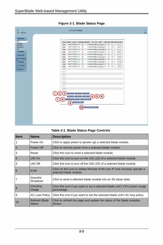
2-1 Blade PageThe first BLADE option in the BLADE SYSTEM submenu allows you to check the status of all the blade modules in the system including power status, KVM status, UID status, error status and management. The command icons below the blade status list allows you to perform various functions, as shown in Figure 2-1 and described in Table 2-1.
To perform a function, first click the box(es) next to the blade(s) you wish to issue a command to and then click the command button below.
NOTE: You can also click on any of the individual blades listed for a remote console to bring up a page with details about that particular blade.
NOTE: Monitor sensors will only be displayed for a blade if it is powered on.
The last column for the Blade Status page table allows you to shutdown/throttle the CPU power to a specified level when required power exceeds the system’s available power.
• If it's set to 0, that blade will be shut down forcefully by the CMM
• If it's set to 50, the CMM will send a signal to throttle down the CPU
• If it's set to 100, the CMM will keep it running at normal speed
2-1
SuperBlade Web-based Management Utility
Figure 2-1. Blade Status Page
Table 2-1. Blade Status Page Controls
Item Name Description
1 Power On Click to apply power to (power up) a selected blade module.
2 Power Off Click to remove power from a selected blade module.
3 Reset Click this icon to reset a selected blade module.
4 UID On Click this icon to turn on the UID LED of a selected blade module.
5 UID Off Click this icon to turn off the UID LED of a selected blade module.
6 KVMClick on this icon to initiate Remote KVM over IP and remotely operate a selected blade module.
7Graceful Shutdown
Click to send a selected blade module into an S5 sleep state.
8CPU/Pwr Usage
Click this icon if you want to set a selected blade unit’s CPU power usage percentage.
9 AC Loss Policy Click this icon if you want to set the selected blade unit’s AC loss policy.
10Refresh Blade Status
Click to refresh the page and update the status of the blade modules shown.
1 2 34 5 6
7 89
10
2-2

Chapter 2: Blade System
2-2 Power SupplyClick on POWER SUPPLY to reveal the POWER SUPPLY STATUS page (Figure 2-2). The POWER SUPPLY option in the BLADE SYSTEM submenu allows you to check the status of all the power supplies in the system you are accessing. Power status (on or off), temperature, fan RPM, wattage, firmware version and FRU version are all shown in the power supply status list. In addition, the commands listed in Table 2-2 may be issued to the power supplies.
To perform a function, first click the box(es) next to the power supplies you wish to issue a command to and then click the command icon.
Figure 2-2. Power Supply Status Page
1 2
4
5
6
3
2-3

SuperBlade Web-based Management Utility
Table 2-2. Power Supply Status Page Controls
Item Name Description
1 Power On Click this to power up a selected power supply.
2 Power Off Click this to shut down a selected power supply.
3
Power Management Redundancy Policy
You may change your selection for the Power Management Redundancy Policy by selecting an option from the drop-down list box and pressing the APPLY button.
4Power Supply Fan Speed Control Option
If you change the FAN CONTROL option from AUTO CONTROL to USER CONTROL, you may alter the speed of the power supply fans by clicking one of the fan icons for Centralized Power Supply Fan Speed Control as described below. Otherwise leave at Auto Control for the system to control fan speed.
5Power Supply Fan Speed Control
Set to minimum speed by clicking the icon numbered “1” and to maximum speed by clicking the icon numbered “4”. The icons numbered “2” and “3” are for incremental increases between the minimum and maximum settings.
After changing the fan speed, you should see the fan RPM change in the status page. Settings affect all fans simultaneously, you cannot control the speed of individual fans.
6Refresh Power Supply Status
Click to refresh the page and update the status of the power supplies shown.
2-4

Chapter 2: Blade System
2-3 Ethernet SwitchClick on ETHERNET SWITCH to reveal the ETHERNET SWITCH STATUS page (Figure 2-3). The ETHERNET SWITCH option in the BLADE SYSTEM submenu allows you to check the status of all the GbE modules in the system you are accessing. Power status (on or off), voltage levels, temperature, error status and initialization status are all shown in the main page (see Table 2-3). In addition, the commands listed below may be issued to the GbE module.
To perform a function, first click the box(es) next to the GbE module(s) you wish to issue a command to and then click the command icon.
Figure 2-3. Ethernet Switch Status Page
4 5 6
2
3
7
1
2-5

SuperBlade Web-based Management Utility
NOTE: Initially, you must manually enter the IP address for each GbE switch to gain access to it. Each IP address should be unique when there are multiple GbE switches on the same network segment.
After gaining access to the GbE switch(es), you can use the reset button to reset their configurations to the default settings. The reset button will reset all GbE switch configurations, including IP address and so on.
Table 2-3. Gibabit Switch Status Page Controls
Item Name Description
1Gigabit Switch Status
Click on a switch listed in this section to manage and configure that GbE switch.
210Gb Pass-Through Status
Click on a switch listed in this section to manage and configure that 10Gb pass-through switch.
310Gb Switch Status
Click on a switch listed in this section to manage and configure that 10Gb switch.
4 Power On Click this icon in each section to power up a selected GbE module.
5 Power Off Click this icon in each section to shut down a selected GbE module.
6 HW Reset Click this icon in each section to reset a GbE module to its default settings.
7Refresh Gigabit Switch Status
Click this icon to refresh the page and update the status of a switch shown.
2-6

Chapter 2: Blade System
2-4 InfiniBand SwitchClick on INFINIBAND SWITCH to reveal the INFINIBAND SWITCH STATUS page (Figure 2-4). The INFINIBAND SWITCH option in the BLADE SYSTEM submenu allows you to check the status of the INFINIBAND SWITCH module in the system you are accessing.
Figure 2-4. InfiniBand Switch Status Page
Table 2-4. InfiniBand Switch Page Controls
Item Name Description
1InfiniBand Switch Status
Use this section to select, power on, power off or reset InfiniBand switches installed in your system.
2IP QDR Switch Status
Use this section to select, power on, power off or reset Infiniband QDR switches installed in your system.
3IP FDR Switch Status
Use this section to select, power on, power off or reset InfiniBand FDR switches installed in your system.
1
3
2
2-7
SuperBlade Web-based Management Utility
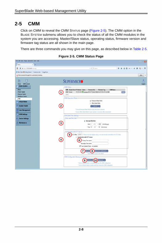
2-5 CMMClick on CMM to reveal the CMM STATUS page (Figure 2-5). The CMM option in the BLADE SYSTEM submenu allows you to check the status of all the CMM modules in the system you are accessing. Master/Slave status, operating status, firmware version and firmware tag status are all shown in the main page.
There are three commands you may give on this page, as described below in Table 2-5.
Figure 2-5. CMM Status Page
1
2
3
4
5
6
7 8
9 10
2-8

Chapter 2: Blade System
Table 2-5. CMM Status Page Controls
Item Name Description
1 CMM StatusUse this section to view the status of CMM modules installed in your system.
2CMM Operation Mode
Use this control to specify either Enterprise Blade Mode or Office Blade Mode for your CMM Operation. Choose Enterprise Blade Mode for high performance operation or Office Blade Mode for quiet operation in a low noise office environment.
In Enterprise Blade Mode the fan speed and performance is higher. In Office Blade Mode the fan speed is lower, generating less noise.
3User Specified Time
This option allows the user to enter the time values for the SIMCM internal real-time clock.
4Synchronize with NTP Server
Click this to synchronize the CMM's real-time clock with the NTP (Network Time Protocol) server.
5 UTC Offset This pull-down menu allows you to offset the UTC Timer.
6Primary/Secondary Time Server
Enter the IP Address for the primary or secondary NTP server that you want to synchronize with the CMM internal real-time clock.
NOTE: Daylight savings time cannot be automatically adjusted. Please manually set up the UTC offset twice a year to compensate for daylight savings time.
7 Apply Click this icon to apply changes you have made in this page.
8Reset to Defaults
Click this icon to restore default status to the controls in this page.
9 Backup Click to download and save the CMM configuration.
10 Restore Click to select and then restore the CMM configuration.
2-9

SuperBlade Web-based Management Utility
Notes
2-10
Chapter 3Virtual Media
The VIRTUAL MEDIA menu allows you to configure the various media and drive systems in your SuperBlade system. Clicking the VIRTUAL MEDIA icon allows you to access the following pages through its sub-menus:
• Floppy Disk
• CD-ROM
• Drive Redirection
• Options
3-1

SuperBlade Web-based Management Utility
3-1 Floppy DiskThe FLOPPY DISK option in the VIRTUAL MEDIA submenu allows you to emulate a floppy drive in the host system to upload images to a remote blade module. The FLOPPY DISK STATUS page (Figure 3-1) that appears and its controls (Table 3-1) are shown below.
Figure 3-1. Floppy Disk Status Page
Table 3-1. Floppy Disk Status Page Controls
Item Name Description
1Active Image (Drive1)
This box displays if any virtual device/image has been connected to the remote host.
2Active Image (Drive2)
This box displays if any virtual device/image has been connected to the remote host.
3Floppy Image Upload
This option allows the user to upload the floppy image located in the remote host as “floppy”. The floppy image uploaded should be in binary format with a maximum size of 1.44 MB. It will be loaded to the Supermicro SIMCM card and will be emulated to the host as a USB device.
4 Virtual DriveSelect a drive in the remote host as the destination drive to upload your image data to.
5Floppy Image File
Click “Browse” to preview and select the files that you wish to upload to the selected host drive.
6 UploadOnce the correct file name appears in the box, click here to upload the floppy image to the drive specified in the remote host.
1
2
3 45
6
3-2

Chapter 3: Virtual Media
3-2 CD-ROMThe CD-ROM IMAGE option allows you to emulate a CD-ROM drive in the host system to upload images to a remote blade module. The CD-ROM IMAGE page (Figure 3-2) and its controls (Table 3-2) are shown below.
Figure 3-2. CD-ROM Image Page
Table 3-2. CD-ROM Image Page Controls
Item Name Description
1Active Image (Drive1)
This box displays if any virtual device/image has been connected to the remote host.
2Active Image (Drive2)
This box displays if any virtual device/image has been connected to the remote host.
3Image on Windows Share
This allows the user to decide how to share the CD-ROM ISO image file with users in the remote host.
4 Virtual Drive Specify the drive that you want to share your data with in the remote host.
5 Share HostKey in the IP Address or the name of the system you wish to share data with via Windows Share.
6 Share NameKey in the name of the shared folder you wish to share data with in the remote host.
7 Path to ImageKey in the location of source files that you wish to share via Windows Share.
8User/Password (Optional)
Key in the Username and password for the person to access the data that you want to share and click “Set” to enter your selections.
9 SetOnce you have set your parameters on this page, press the Set button to set you selected parameters for uploading images to a remote blade module
1
2
3
4
56
7
9
8
3-3
SuperBlade Web-based Management Utility
3-3 Drive RedirectionThe DRIVE REDIRECTION option in the VIRTUAL MEDIA submenu allows you to configure redirection settings. The DRIVE REDIRECTIONS page (Figure 3-3) and its controls (Table 3-3) are shown below.
Figure 3-3. Drive Redirections Page
Table 3-3. Drive Redirection Page Controls
Item Name Description
1Active Image (Drive1)
This box displays if any virtual device/image has been connected to the remote host.
2Active Image (Drive2)
This box displays if any virtual device/image has been connected to the remote host.
3Drive Redirection
Use this to configure DRIVE REDIRECTION settings.
4Disable Drive Redirection
Check the box to disable Drive Redirection. Once this function is disabled, local drives will not be accessible for other remote systems users.
5Force Read Only Connections
Check this box to allow the data stored in local drives to be read by a remote system, but not overwritten (for data integrity and system security purposes).
6 ApplyAfter configuring your settings, click “Apply” to initiate drive redirection with the parameters you've set.
7Reset to Defaults
You can also key in your own setting values and re-set these values as “default” by clicking on this icon to reset the defaults.
1
2
3
4
65
7
3-4
Chapter 3: Virtual Media
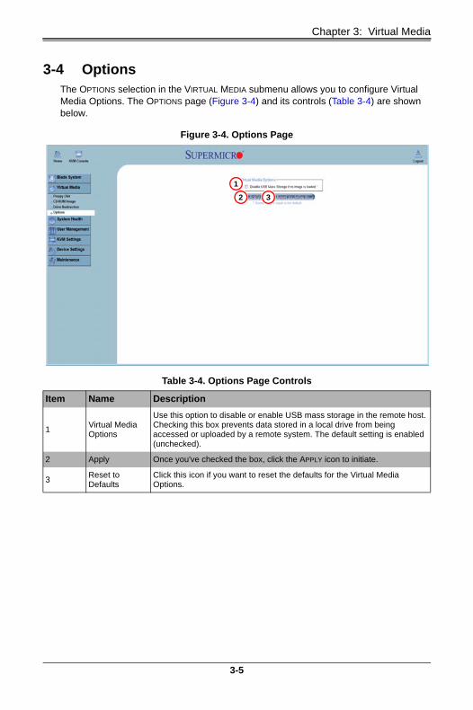
3-4 OptionsThe OPTIONS selection in the VIRTUAL MEDIA submenu allows you to configure Virtual Media Options. The OPTIONS page (Figure 3-4) and its controls (Table 3-4) are shown below.
Figure 3-4. Options Page
Table 3-4. Options Page Controls
Item Name Description
1Virtual Media Options
Use this option to disable or enable USB mass storage in the remote host. Checking this box prevents data stored in a local drive from being accessed or uploaded by a remote system. The default setting is enabled (unchecked).
2 Apply Once you've checked the box, click the APPLY icon to initiate.
3Reset to Defaults
Click this icon if you want to reset the defaults for the Virtual Media Options.
1
2 3
3-5

SuperBlade Web-based Management Utility
Notes
3-6
Chapter 4System Health
The SYSTEM HEALTH menu allows you to access and configure logs and alert settings in your SuperBlade system. Clicking the SYSTEM HEALTH icon allows you to access the following pages through its sub-menus:
• System Event Log
• Alert Settings
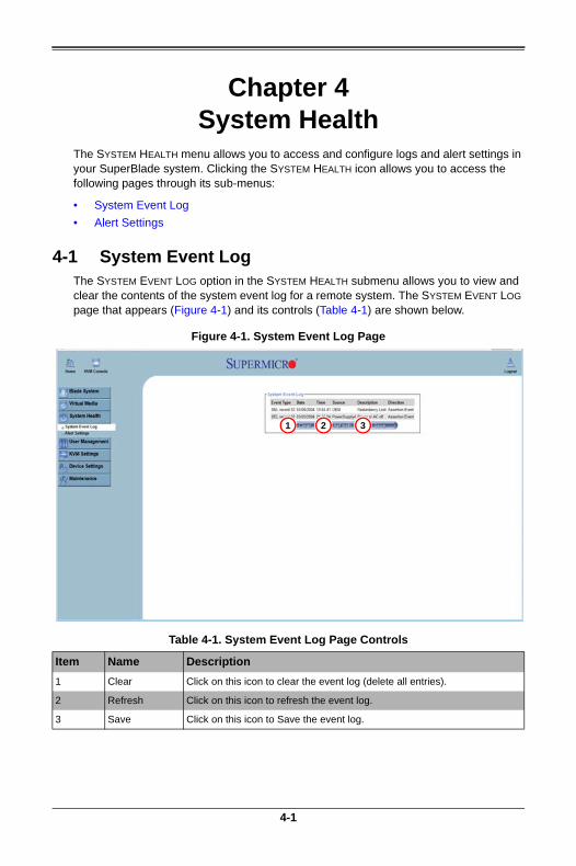
4-1 System Event LogThe SYSTEM EVENT LOG option in the SYSTEM HEALTH submenu allows you to view and clear the contents of the system event log for a remote system. The SYSTEM EVENT LOG page that appears (Figure 4-1) and its controls (Table 4-1) are shown below.
Figure 4-1. System Event Log Page
Table 4-1. System Event Log Page Controls
Item Name Description
1 Clear Click on this icon to clear the event log (delete all entries).
2 Refresh Click on this icon to refresh the event log.
3 Save Click on this icon to Save the event log.
1 2 3
4-1
SuperBlade Web-based Management Utility
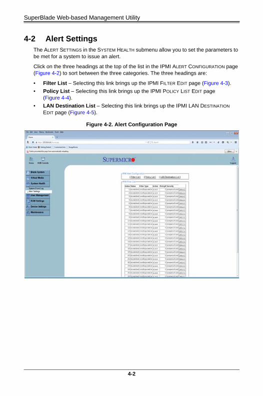
4-2 Alert SettingsThe ALERT SETTINGS in the SYSTEM HEALTH submenu allow you to set the parameters to be met for a system to issue an alert.
Click on the three headings at the top of the list in the IPMI ALERT CONFIGURATION page (Figure 4-2) to sort between the three categories. The three headings are:
• Filter List – Selecting this link brings up the IPMI FILTER EDIT page (Figure 4-3).
• Policy List – Selecting this link brings up the IPMI POLICY LIST EDIT page (Figure 4-4).
• LAN Destination List – Selecting this link brings up the IPMI LAN DESTINATION EDIT page (Figure 4-5).
Figure 4-2. Alert Configuration Page
4-2

Chapter 4: System Health
IPMI Filter Edit
Clicking the FILTER LIST link brings up IPMI FILTER EDIT page (Figure 4-3). In this page you can set an IPMI Alert Filter using controls for Filter Number, Status, Action, Alert Policy and Event Severity.
IPMI Policy List Edit
Clicking the POLICY LIST link brings up IPMI POLICY LIST EDIT page (Figure 4-4). In this page you can set an IPMI Alert Policy using controls for Index number, Status, Policy Set, Policy, Channel Number, Destination and Alert String.
Figure 4-3. IPMI Filter Edit Page
Figure 4-4. IPMI Policy List Edit Page
4-3

SuperBlade Web-based Management Utility
IPMI LAN Destination Edit
Clicking the LAN DESTINATION LIST link brings up IPMI LAN DESTINATION EDIT page (Figure 4-5). In this page you can set an IPMI Alert LAN Destinations using controls for the Destination Number, Acknowledge, Timeout, Retries and Alert Type.
Additionally, this page contains controls for IPMI LAN Alert Global Options that include Community String, SMTP Server and Email Sender Address.
Figure 4-5. IPMI LAN Destination Edit Page
4-4

Chapter 5User Management
The USER MANAGEMENT menu allows you to configure users for your SuperBlade system. Clicking the USER MANAGEMENT icon allows you to access the following pages through its sub-menus:
• Change Password
• Users & Groups
• Permissions
5-1 Change PasswordThe CHANGE PASSWORDS page (Figure 5-1) is where you can change the password used to access the Web-based Management Utility. Its controls are shown in Table 5-1.
Figure 5-1. Change Passwords Page
Table 5-1. Change Password Page Controls
Item Name Description
1 New Password Type your new password in the window.
2Confirm New Password
Type your new password in this second window to confirm.
3 Apply Click this icon to apply the changes you made.
12
3
5-1

SuperBlade Web-based Management Utility
5-2 Users & GroupsThe USERS & GROUPS page (Figure 5-2) is where you specify and manage groups and users, which helps you manage the remote systems you are managing. Its controls are shown in Table 5-2.
Figure 5-2. Users and Groups Page
Table 5-2. Users and Groups Page Controls
Item Name Description
1User Management Section
This section displays the user's information.
2Existing Users/Groups
Select an existing user/group for information updates. Once you make a selection, click on the Lookup icon on the right to view the information.
3New Users/Groups Name
Type in a new user/group name in this field.
4 Full User Name Type in the user's full name in this field.
5Password and Confirm Password
Type the user's password in the window and then retype the password in the next window to confirm. The password must at least four characters in length.
6 Email Address Type in the user's email address in this window (optional).
7 Mobile Phone Type in the user's mobile phone number (optional).
12
34
56
7
8
9
10
11
12 13 14 15
162
3
12 13 14 15
5-2
Chapter 5: User Management
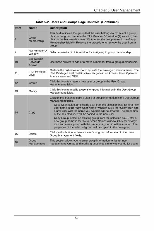
8Group Membership
This field indicates the group that the user belongs to. To select a group, click on the group name in the “Not Member Of” window (9) select it, then click on the backwards arrow (10) to enter the group name in the Group Membership field (8). Reverse the procedure to remove the user from a group.
9Not Member Of Window
Select a member in this window for assigning to group membership.
10Backwards/Forwards Arrows
Use these arrows to add or remove a member from a group membership.
11IPMI Privilege Level
Click on the pull-down arrow to activate the Privilege Selection menu. The IPMI Privilege Level contains five categories: No Access, User, Operator, Administrator and OEM.
12 CreateClick this icon to create a new user or group in the User/Group Management fields.
13 ModifyClick this icon to modify a user's or group information in the User/Group Management fields.
14 Copy
Click on this button to copy a user's or group information in the User/Group Management fields.
Copy User: select an existing user from the selection box. Enter a new user name in the “New User Name” window. Click the “Copy” icon and a new user with the name you typed in will be created. The properties of the selected user will be copied to the new user.
Copy Group: select an existing group from the selection box. Enter a new group name in the “New Group Name” window. Click the “Copy” icon and a new group with the name you typed in will be created. The properties of the selected group will be copied to the new group.
15 DeleteClick on this button to delete a user's or group information in the User/Group Management fields.
16Group Management
This section allows you to enter group information for better user management. Create and modify groups they same way you do for users.
Table 5-2. Users and Groups Page Controls (Continued)
Item Name Description
5-3

SuperBlade Web-based Management Utility
5-3 PermissionsYou can use the PERMISSIONS option to grant and deny access to various IPMI functions in the PERMISSIONS page (Figure 5-3) using its controls (Table 5-3).
Figure 5-3. Permissions Page
Table 5-3. Permissions Page Controls
Item Name Description
1Show Permissions for User/Group
Click on the pull-down arrow to activate the user/group permissions selection menu.
2 Update Click this icon to update the permissions information.
3Effective Permissions
This field indicates the actual permissions a user or group has.
4User Permissions
This field indicates the actual permissions a user has.
5Inherited Group Permission
This field indicates the permissions a user has due to the fact that they belong to a certain group.
1 2
34 5
5-4
Chapter 6KVM Settings
The KVM SETTINGS menu allows you to configure keyboard, mouse and console settings. Clicking the KVM SETTINGS icon allows you to access the following pages through its sub-menus:
• User Console
• Keyboard/Mouse
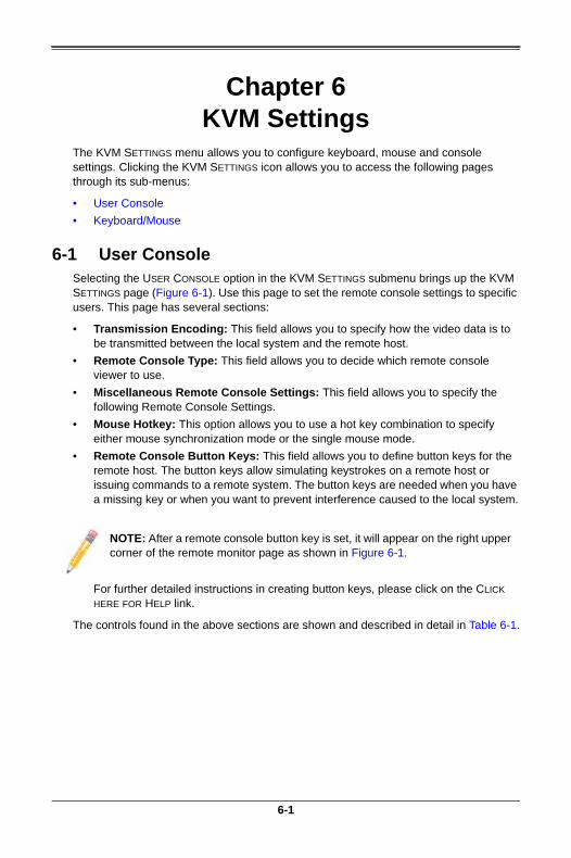
6-1 User ConsoleSelecting the USER CONSOLE option in the KVM SETTINGS submenu brings up the KVM SETTINGS page (Figure 6-1). Use this page to set the remote console settings to specific users. This page has several sections:
• Transmission Encoding: This field allows you to specify how the video data is to be transmitted between the local system and the remote host.
• Remote Console Type: This field allows you to decide which remote console viewer to use.
• Miscellaneous Remote Console Settings: This field allows you to specify the following Remote Console Settings.
• Mouse Hotkey: This option allows you to use a hot key combination to specify either mouse synchronization mode or the single mouse mode.
• Remote Console Button Keys: This field allows you to define button keys for the remote host. The button keys allow simulating keystrokes on a remote host or issuing commands to a remote system. The button keys are needed when you have a missing key or when you want to prevent interference caused to the local system.
For further detailed instructions in creating button keys, please click on the CLICK HERE FOR HELP link.
The controls found in the above sections are shown and described in detail in Table 6-1.
NOTE: After a remote console button key is set, it will appear on the right upper corner of the remote monitor page as shown in Figure 6-1.
6-1
SuperBlade Web-based Management Utility
Figure 6-1. User Console Page
Table 6-1. User Console Page Controls
Item Name Description
1
Remote Console Settings for User
This field allows you to decide which group the user belongs to. Click on the arrow on the right to activate the pull-down menu and highlight the name of the group to select it.
2 UpdateOnce you've selected the group name, click on UPDATE to save the selections.
3Automatic Detection
Select this option to allow the CMM to automatically detect the networking configuration settings (such as the bandwidth of the connection line) and transmit data accordingly.
4 Pre-configured
This item allows the user to select the data transmission settings from a pre-defined options list. The pre-configured settings will provide the best results because the compression and color depth settings will be adjusted for optimization based on the network speed indicated.
5 Network speedOnce you've selected the PRE-CONFIGURED option above, you then can select a desired network speed setting from the pull-down menu by clicking on the arrow.
6Default Java VM (JVM)
Select this option to use the default Java Virtual Machine of your web browser. This can be the Microsoft JVM for Internet Explorer or the Sun JVM depending on the configuration of your browser.
1
10
11 1213
2
3 45
67
89
14 15
6-2

Chapter 6: KVM Settings
7
Sun Microsystems Java Browser Plugin
Select this option when the JVM used to run the code for the Remote Console is a Java Applet. If using this function for the first time and the appropriate Java plugin is not yet installed in your system, you may download and install it automatically. To download and install, you need to check YES in the dialog boxes. Downloading Sun's JVM will allow you to use a stable and identical JVM across different platforms.
NOTE: If your internet connection is slow, please pre-install JVM on your administration system.
8Start in Monitor Mode
Check this box to enable Start in Monitor Mode, which allows data to be displayed on the remote monitor as soon as the Remote Console is activated.
NOTE: The data displayed in the remote monitor is read-only.
9Start in Exclusive Access Mode
Check this box to enable the exclusive access mode immediately upon Remote Console startup, which will force all other users connected to the network to close. No other users can open the Remote Console until you disable this function or log off.
10 HotkeyEnter a hot key combination in the box to specify either mouse synchronization mode or the single mouse mode.
11 Button KeysEnter the syntax of a button key in the box. For detailed instructions on creating button keys, please click on the “Click here for Help” link.
12 NameType in the name of a button key in the box. For detailed instructions on creating button keys, please click on the CLICK HERE FOR HELP link.
13 More Entries Click on this icon to create more button keys.
14 Apply Click this icon to apply the selections you made.
15Reset to Defaults
Click this icon if you want to reset the defaults for the Remote Console button keys.
Table 6-1. User Console Page Controls (Continued)
Item Name Description
6-3
SuperBlade Web-based Management Utility
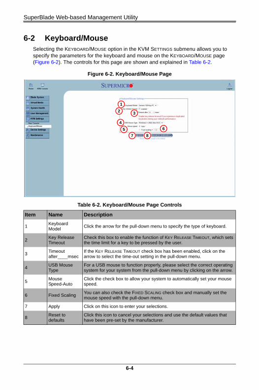
6-2 Keyboard/MouseSelecting the KEYBOARD/MOUSE option in the KVM SETTINGS submenu allows you to specify the parameters for the keyboard and mouse on the KEYBOARD/MOUSE page (Figure 6-2). The controls for this page are shown and explained in Table 6-2.
Figure 6-2. Keyboard/Mouse Page
Table 6-2. Keyboard/Mouse Page Controls
Item Name Description
1Keyboard Model
Click the arrow for the pull-down menu to specify the type of keyboard.
2Key Release Timeout
Check this box to enable the function of KEY RELEASE TIMEOUT, which sets the time limit for a key to be pressed by the user.
3Timeout after____msec
If the KEY RELEASE TIMEOUT check box has been enabled, click on the arrow to select the time-out setting in the pull-down menu.
4USB Mouse Type
For a USB mouse to function properly, please select the correct operating system for your system from the pull-down menu by clicking on the arrow.
5Mouse Speed-Auto
Click the check box to allow your system to automatically set your mouse speed.
6 Fixed ScalingYou can also check the FIXED SCALING check box and manually set the mouse speed with the pull-down menu.
7 Apply Click on this icon to enter your selections.
8Reset to defaults
Click this icon to cancel your selections and use the default values that have been pre-set by the manufacturer.
1
2 3
4
5 6
7 8
6-4

Chapter 7Device Settings
Use the DEVICE SETTINGS menu for configuring network, security and log settings for your SuperBlade system. Clicking the DEVICE SETTINGS icon allows you to access the following pages through its sub-menus:
• Network
• Dynamic DNS
• Security
• Certificate
• Event Log
7-1

SuperBlade Web-based Management Utility
7-1 NetworkClicking the NETWORK option in the DEVICE SETTINGS submenu brings up the NETWORK page (Figure 7-1). Use the below fields in the page to specify network parameters.
• Network Basic Settings: These fields allow you to configure basic network settings.
• Network Miscellaneous Settings: These fields allow you to configure miscellaneous network settings.
• LAN Interface Settings: These fields allow you to configure LAN Interface settings.
The controls in these fields are shown and detailed in Table 7-1.
Figure 7-1. Network Page
Table 7-1. Network Page Controls
Item Name Description
1IP Auto Configuration
Click on the pull-down menu to select a desired item from the list. The options are NONE, DHCP, and BOOTP.
2Preferred Host Name (DHCP only)
Enter a preferred host name here.
3 IP Address Enter the IP address for the remote host here.
4 Subnet Mask Enter the subnet mask of the local network here.
5Gateway IP Address
Enter the local network router's IP address here to provide accessibility for users that are not connected to the local network.
6Primary DNS Server IP Address
Enter the IP address of the Primary Domain Name Server here.
1
1011
1213
15
23
45
67
89
14
1716
7-2

Chapter 7: Device Settings
7Secondary DNS Server IP Address
Enter the IP address of the Secondary Domain Name Server in the box. It will be used when the Primary DNS Server cannot be contacted.
8Remote Console & HTTPS Port
Enter the port numbers the remote host and the HTTP server are listening. If a number is not entered in the box, the default value will be used.
9 HTTP PortEnter the port number the of the HTTP server. If a number is not entered in the box, the default value will be used.
10 SSH PortEnter the port number of the SSH server. If a number is not entered in the box, the default value will be used.
11 Bandwidth LimitEnter the maximum bandwidth value for network interfacing. The value should be in Kbits per second.
12Enable SSH Access
Click this box to enable SSH access.
13Disable Setup Protocol
Check this box to disable the setup protocol function of the SIMBL card.
14LAN Interface Speed
Click on the arrow on the right to select a desired LAN interface speed from the pull-down menu. The options are Auto-detect, 10 Mbps or 100 Mbps. If Auto-detect is selected, the optimized speed will be set based on the system configurations detected by the OS.
15LAN Interface Duplex Mode
Click on the arrow on the right to select a desired LAN interface duplex mode from the pull-down menu. The options are AUTO-DETECT, HALF DUPLEX and FULL DUPLEX. If Auto-detect is selected, the LAN INTERFACE DUPLEX MODE will be set to the optimized setting based on the system configurations detected by the OS.
16 Apply Click this icon to apply the selections you made.
17Reset to Defaults
Click this icon if you want to reset the defaults for the Remote Console button keys.
Table 7-1. Network Page Controls (Continued)
Item Name Description
7-3

SuperBlade Web-based Management Utility
7-2 Dynamic DNSSelecting the DYNAMIC DNS option from the DEVICE SETTINGS submenu brings up the DYNAMIC DNS SETTINGS page (Figure 7-2). Use this page to configure Dynamic DNS settings. Controls for this page are shown and detailed in Table 7-2.
Figure 7-2. Dynamic DNS Settings Page
Table 7-2. Dynamic DNS Settings Page Controls
Item Name Description
1Enable Dynamic DNS
Check this box to enable Dynamic DNS.
2Dynamic DNS Server Link
Click the www.dyndns.org: link to access the DynDNS web site. This is the server name where the DDNS Service is registered.
3 DNS System
If Dynamic DNS is enabled, you can select either CUSTOM or DYNAMIC from the pull-down menu. Select CUSTOM to use your own system as the DNS server. Select DYNAMIC to use the pre-configured Dynamic DNS as your server.
4 Hostname Enter the name you want to use for the remote host server.
5 Username Enter the username for the remote host user.
6 Password Enter the password for the remote host user.
7Check time (HH:MM)
Enter the time the SIMCM card first registers with the DNS server in the HH:MM format (such as: 07:25 or 19:30).
8 Check Interval Enter the time interval for the IPMI to report to the Dynamic DNS again.
12
34
56
78
9
10 11
7-4

Chapter 7: Device Settings
9Delete Saved External IP Address
Click this icon to delete the IP address for an external system that has been previously entered and saved.
10 Apply Click this icon to apply the selections you made.
11Reset to Defaults
Click this icon if you want to reset the defaults for the Remote Console button keys.
Table 7-2. Dynamic DNS Settings Page Controls
Item Name Description
7-5

SuperBlade Web-based Management Utility
7-3 SecuritySelecting the SECURITY option from the DEVICE SETTINGS submenu brings up the SECURITY page (Figure 7-3). Use this page to configure the Security settings. Controls for this page are shown and detailed in Table 7-3.
• Encryption Settings: This field allows you to configure encryption settings.
• IP Access Control: This section allows you to configure the IP Access Control settings listed below.
• User Blocking: This field allows you to set the user blocking conditions.
Figure 7-3. Security Page
Table 7-3. Security Page Controls
Item Name Description
1Force HTTPS for Web Access
Check this box to enable Force HTTPS for Web Access. If enabled, you will need to use an HTTPS connection to access the web management utility.
2 KVM Encryption
This option allows you to configure the encryption of the RFB protocol. RFB is used by the remote host to transmit video data displayed in the host monitor to the local administrator machine and to transmit keyboard and mouse data from the local administrator machine back to the remote host.
If set to OFF, no encryption will be used. If set to TRY, the applet (JVM of the remote host) will attempt to make an encrypted connection. In this case, when a connection cannot be established, an unencrypted connection will be used. If set to FORCE, the applet will make an encrypted connection. In this case, an error will be reported if no connection is made.
3Enable IP Access Control
Check this box to enable IP Access Control. This function is used to limit user access to the network by identifying them by their IP address (available to the LAN interface only.)
1
10 11
1213
2
34
5 6 7
8 9
15 16
14
7-6

Chapter 7: Device Settings
4 Default Policy
When IP ACCESS CONTROL is enabled, you can select either Accept or Drop from this pull-down menu to either allow or deny access according to pre-defined rules.
NOTE: If set to DROP and you do not have a set of rules that will accept the Internet connection, then an Internet connection over the LAN is impossible. In this case, you need to change your security settings via modem or by disabling the IP ACCESS CONTROL.
5 Rule#Enter a rule number in the box for a command (or commands) that will be used by the IP ACCESS CONTROL.
6 IP/MaskEnter the IP address or an IP address range for which the command(s) will be applied.
7 Policy
This item instructs the IPMI what to do with the matching packages.
NOTE: The sequence or the order of the rules is important; rules are checked in ascending order until one matches. All rules below the matching one will be ignored. The default policy applies if no matching rules are found.
8 AppendSelect this option to add IP Address/Mask, rules or commands to the existing ones.
9 InsertSelect this option to insert IP Address/Mask, rules or commands to the existing ones.
10 ReplaceSelect this option to replace an old IP Address/Mask, rule or command with a new one.
11 DeleteSelect this option to delete (a part of) an existing IP Address/Mask, rule or command.
12Max. Number of Failed Logins
Enter the maximum number of failed attempts or failed logins allowed for a user. If the number of failed logins or attempts exceeds this maximum number allowed, the user will be blocked from the system.
NOTE: If this box is left empty, the user is allowed to try to login to the server indefinitely. For network security, this is not recommended.
13Block Time (Minutes)
Enter the number of minutes allowed for a user to attempt to login. If the user fails to login within this time allowed, the user will be blocked from system.
NOTE: If this box is left empty, the user is allowed to try to login to the server indefinitely. For network security, this is not recommended.
14 SMC RKMPThese controls show you the SMC RKMP status and allow you to enable or disable SMC RKMP.
15 Apply Click this icon to apply the selections you made.
16Reset to Defaults
Click this icon if you want to reset the defaults for the Remote Console button keys.
Table 7-3. Security Page Controls (Continued)
Item Name Description
7-7

SuperBlade Web-based Management Utility
7-4 CertificateSelecting the CERTIFICATE option from the DEVICE SETTINGS submenu brings up the CERTIFICATE page (Figure 7-4). Use this page to configure the Certificate settings for your blade servers. Controls for this page are shown and detailed in Table 7-4. Use the procedure below for assigning and uploading a certificate file.
Configuring Certificate Settings
1. To enter a new SSL certificate, press the BROWSE button to select an SSL certificate from your system.
NOTE: SHA2 and RSA 2048-bit SSL are supported.
2. To enter a new Private Key, press the BROWSE button to select a Private Key from your system.
3. After entering both the SSL certificate and the Private Key click the Upload button to upload both to your system.
Figure 7-4. Certificate Page
Table 7-4. Certificate Page Controls
Item Name Description
1SSL Certificate BROWSE button
Use this button to select an SSL Certificate file from your system.
2Private Key BROWSE button
Use this button to select an Private Key file from your system.
3 UPLOAD ButtonUse this button to upload the selected SSL Certificate and Private Key files.
12
3
7-8

Chapter 7: Device Settings
7-5 Event LogSelecting the EVENT LOG option from the DEVICE SETTINGS submenu brings up the DEVICE SETTINGS EVENT LOG page (Figure 7-5). Use this page to set event log targets and assignments. Controls for this page are shown and detailed in Table 7-5.
• Event Log Targets: This section allows you to manually set the event log targets and settings.
• Event Log Assignments: This window allows you to specify the types and the destination for the event logging.
Figure 7-5. Device Settings Event Log Page
Table 7-5. Device Settings Event Log Page Controls
Item Name Description
1List Logging Enabled
Check this box to activate the event-logging list. To show the event log list, click on EVENT LOG under SYSTEM HEALTH.
NOTE: The maximum number of log list entries is 1,000 events. Every entry that exceeds this limit will automatically override the oldest one in the list. If the reset button is pressed, all logging information will be saved, however, all logging data will be lost if a hard reset is performed or the system loses power.
2Entries Shown Per Page
Enter the number of entries you want to display on a page.
3Clear Internal Log
Click this icon to clear the internal event log from memory.
1
1011
1213
15
23
56
7
89
14
16
4
17
7-9

SuperBlade Web-based Management Utility
4NFS Logging Enabled
Click this box to enable NFS Logging, which will create a Network File System (NFS) for the event logging data to be written into.
5 NFS Server Enter the IP Address of the NFS server here.
6 NFS ShareEnter the path of the Network File System in which the event logging data is stored.
7 NFS Log FileEnter the filename of the Network File System in which the event logging data is stored.
8SMTP Logging Enabled
Check this box to enable the SMTP (Simple Mail Transfer Protocol) logging.
9 SMTP Server Enter the IP Address for the SMTP server.
10Receiver Email Address
Enter the email address that the SMTP event logging data will be sent to.
11Sender Email Address
Enter the email address from which the SMTP event logging data is sent.
12SNMP Logging Enabled
Check this box to enable SNMP (Simple Network Management Protocol) logging.
13 Destination IP Enter the IP address where the SNMP trap will be sent to.
14 CommunityEnter the name of the community if the receiver requires a community string.
15Event Log Assignments
Check the check boxes in this section to include the designated assignment to the event log.
16 Apply Click this icon to apply the selections you made.
17Reset to Defaults
Click this icon if you want to reset the defaults for the Remote Console button keys.
Table 7-5. Device Settings Event Log Page Controls (Continued)
Item Name Description
7-10

Chapter 8Maintenance
Use the MAINTENANCE menu for maintenance configurations on your SuperBlade system. Clicking the MAINTENANCE icon allows you to access the following pages through its sub-menus:
• Device Information
• Event Log
• Update Firmware
• Unit Reset
8-1 Device InformationClicking the DEVICE INFORMATION option in the MAINTENANCE submenu brings up the DEVICE INFORMATION page (Figure 8-1), which provides system information. The controls for this page are detailed in Table 8-1.
Figure 8-1. Device Information Page
Table 8-1. Device Information Page Controls
Item Name Description
1Device Information
This field displays information on the SIMCM card and its firmware.
2View the Data File for Support
Click on this link to view the XML file which contains product information that is needed for technical support.
3Connected Users
List the name(s), the IP Address(es) and the status of the connect user(s).
1
2
3
8-1

SuperBlade Web-based Management Utility
8-2 Event LogClicking the EVENT LOG option in the MAINTENANCE submenu brings up the MAINTENANCE EVENT LOG LIST page (Figure 8-2). This page contains information on events that are recorded by the SIMCM in the order of Date/Time, Types and Descriptions including the IP address(es), user(s) and activities involved.
Figure 8-2. Maintenance Event Log List Page
8-2

Chapter 8: Maintenance
8-3 Update FirmwareClicking the UPDATE FIRMWARE option in the MAINTENANCE submenu brings up the UPDATE FIRMWARE page (Figure 8-3). This page is where you can update the firmware for the SIMCM card in the CMM module. The controls for this page are detailed in Table 8-2.
Figure 8-3. Update Firmware Page
NOTE: This process is not reversible once the firmware is updated, so proceed with caution. It might take a few minutes to complete this procedure.
Table 8-2. Update Firmware Page Controls
Item Name Description
1 Firmware FileEnter the name of the firmware you want to update or click BROWSE to select the file.
2 UploadClick on the UPLOAD icon to upload the firmware file to the server for the update.
12
8-3

SuperBlade Web-based Management Utility
8-4 Unit ResetClicking the UNIT RESET option in the MAINTENANCE submenu brings up the UNIT RESET page (Figure 8-4), which allows you to reset USB and Device components. The controls for this page are detailed in Table 8-3.
Figure 8-4. Unit Reset Page
Table 8-3. Unit Reset Page Controls
Item Name Description
1Reset Keyboard/Mouse (USB)
Click the RESET icon to reset the Keyboard/Mouse (USB) module.
2 Reset USB Click the RESET icon to reset the USB module.
3Reset Video Engine
Click the RESET icon to reset the Video Engine module.
4 Reset Device Click the RESET icon to cold reset the utility's firmware.
1
2
3
4
8-4

Chapter 9Remote Console
This chapter covers the use of the Remote Console in the Web-based Management Utility software. Activating the remote console may be done in two ways:
• Home Page: On the HOME page, click on the CONSOLE icon in the upper left area of the page.
• Blade System Menu: Click the BLADE SYSTEM icon on the left of the page, then click BLADE in the submenu. A page will open with a list of blades.
The blade units listed are hyperlinks - click one of these to open a page giving details on that blade unit. In each page you will see a REMOTE CONSOLE PREVIEW pane. At the top is a link that reads CLICK TO OPEN. Click this link to open the remote console.
9-1

SuperBlade Web-based Management Utility
9-1 Remote Console Interface PageWhatever option you use, it allows the local host to interact with a remote server through the REMOTE CONSOLE INTERFACE page (Figure 9-1). This page allows you to share files stored in the local drive with a user connected to the remote server, download data from a local drive to the remote server, issue commands to manage the remote server or allow the remote server be controlled and managed by a local user logged in to the remote server (see Table 9-1 for a list of controls). This function provides a full spectrum of remote console interaction and management.
Figure 9-1. Remote Console Interface Page
Table 9-1. Remote Console Interface Page
Item Name Description
1Drive Page Button
Click on this button to open and display the DRIVE REDIRECTION page and its controls. See "Drive Redirection Page" below for details.
2Adjust Page Button
Click on this button to adjust the page size.
1
2
9-2

Chapter 9: Remote Console
9-2 Drive Redirection PageThe DRIVE REDIRECTION page is shown in Table 9-2 and its controls are listed in Table 9-2.
Figure 9-2. Drive Redirection Page
To use this function, you need to click the FLOPPY hot key button displayed on the upper right corner of the page.
Click the CTRL+ALT+DELETE button to send the command CTRL+ALT+DELETE to the remote server for execution.
Once you have clicked on the button, it displays a message asking you to confirm if you really want to send CTRL+ALT+DELETE. Click YES to confirm or click CANCEL to cancel sending the command for remote execution.
Table 9-2. Drive Redirection Page Controls
Item Name Description
1 Connect Drive
Click this button to bring up a window with secondary controls for Local Drive list, Refresh, Sending Commands and Write Support (see below for details on these controls).
Once you have clicked CONNECT, users logged into remote servers will have access to the local drive that you have selected.
2 Connect ISO Click this button to allow you to redirect an CD/DVD ISO image.
3 DisconnectClick this button to cancel the connection established between a local drive and a remote server. Once you click this button, the drive you have selected will not be accessible for remote console interface.
Local Drive ListThis pull-down menu displays a list of local drives available for remote access. Select from the list a local drive that you want to make accessible for a remote server.
Refresh Click this button to refresh the local drive list.
Write Support
Check this button to allow the remote operating system to have write access to the drive that you have selected. This function allows a user to alter, overwrite, erase and destroy data stored in the drive selected and therefore should only be used on drives with non-critical data. When WRITE SUPPORT is checked, a warning message will display. Read the warning message carefully before enabling this function.
Sending CommandsThis functions allows the user to issue a pre-defined command to a remote server for execution.
NOTE: Hot keys are commands that have been pre-defined and pre-stored in a remote consoles.
1 2 3
9-3

SuperBlade Web-based Management Utility
9-3 Remote Console OptionsAfter the remote console page appears, click on OPTION in the upper right corner to display the OPTIONS menu as shown in Figure 9-3.
Figure 9-3. Remote Console Options
The following items are included in the OPTIONS Menu and described in more detail in the sections below:
• Monitor Only
• Exclusive Access
• Readability Filter
• Scaling
• Local Cursor
• Chat Window
• Video Settings
• Soft Keyboard
• Local Keyboard
• Hotkeys
Monitor Only
Click MONITOR ONLY to turn the Monitor Only function on or off. If MONITOR ONLY is selected, the KB/MOUSE icon on the lower right corner will be crossed out and the user can only view or monitor remote console activities. Also, any remote console interaction will no longer be available.
Exclusive Access
With the appropriate permission, a user can force other users to quit the remote console and claim the console for their own exclusive use by clicking on EXCLUSIVE ACCESS. When this function is selected, the second user icon on the lower left corner of the page will be crossed out.
Readability Filter
Click on this to turn the Readability Filter on or off. Turn on this function to preserve most of the page details even when the page image is substantially scaled down.
9-4

Chapter 9: Remote Console
Scaling
This item allows the user to scale the remote console page to the desired size. Click on this button to access its submenu and select the desired setting from the options listed in the submenu: 25%, 50%, 100% and SCALE TO FIT.
Local Cursor
This item allows the user to choose the desired shape for the local cursor. Click on this button to access its submenu and select a desired shape from the options listed in the submenu: TRANSPARENT, DEFAULT, BIG, PIXEL and CROSS-HAIR. The availability of the shapes depends on the Java Virtual Machine used.
Chat Window
This item allows the user to communicate with other users logged in to the same remote host. The page below shows a CHAT WINDOW displayed in a scaled down remote console page (see Figure 9-4). The window’s controls are shown in Table 9-3.
Figure 9-4. Chat Window
NOTE: This item is available for systems with JVM 1.4 or higher.
NOTE: Once you've typed a message in the chat line box and pressed <ENTER>, your message will be sent to remote systems and read by other users. Please review the text displayed in the chat line box before you hit <ENTER>.
1
2
3 4
9-5

SuperBlade Web-based Management Utility
Video Settings
This item allows the user to set the monitor display settings by clicking on the VIDEO SETTINGS button. After you've clicked the VIDEO SETTINGS button, the submenu displays as shown in Figure 9-5.
Figure 9-5. Video Settings
Use your cursor pointer to click on the left and right arrows to adjust the setting for the HORIZONTAL OFFSET and VERTICAL OFFSET.
If you are not happy with the changes you've made, you can click the RESET THIS MODE button to reset a particular item, or click on the RESET ALL MODES button to reset all items. To save all changes, click on the SAVE CHANGES button. You can also click on UNDO CHANGES to abandon the changes.
Soft Keyboard
This item allows the user to use the soft keys that have been pre-installed in the Soft Keyboard of the particular language selected. Click on SHOW BUTTON to show a soft keyboard which contains pre-installed soft keys (see Figure 9-6). Click on MAPPING to display a list of major world languages. When the language list displays, select the language you want to use by clicking on it (see Figure 9-7).
Figure 9-6. Keys in English Soft Keyboard
Table 9-3. Items in the Chat Window
Item Name Description
1 Title Bar This shows the IP address of the remote host you are connected to.
2Chat Window Frame
This frame displays chat messages, including your own messages that have been sent to other users. This is a read-only test display area.
3User's Identity Label
This line displays your own identity.
4 Chat Line This is an editable text line where you can enter a new message.
9-6

Chapter 9: Remote Console
Figure 9-7. Soft Keyboard Language Selection
Local Keyboard
This item allows the user to manually change the local keyboard setting for interaction with a remote host. Use this function to change the language mapping of your browser machine running the remote console host. After you have clicked LOCAL KEYBOARD button, a language submenu displays. When this language list displays, select the language you want to use.
Hotkeys
This item allows the user to select a pre-defined hot key from a list. Once a hot key is selected, the command associated with the hot key will be sent to the remote console host for execution.
After you've clicked the HOTKEY button, the submenu displays as shown in Figure 9-8.
Figure 9-8. Hotkeys
9-7

SuperBlade Web-based Management Utility
Notes
9-8

Disclaimer
The products sold by Supermicro are not intended for and will not be used in life support systems, medical equipment, nuclear facilities or systems, aircraft, aircraft devices, aircraft/emergency communication devices or other critical systems whose failure to perform be reasonably expected to result in significant injury or loss of life or catastrophic property damage. Accordingly, Supermicro disclaims any and all liability, and should buyer use or sell such products for use in such ultra-hazardous applications, it does so entirely at its own risk. Furthermore, buyer agrees to fully indemnify, defend and hold Supermicro harmless for and against any and all claims, demands, actions, litigation, and proceedings of any kind arising out of or related to such ultra-hazardous use or sale.

SuperBlade Web-based Management Utility User’s Manual