parker valves pdn1000us brass-poppet sliding-seal
DESCRIPTION
detalle técnico de tipos de valvularTRANSCRIPT

Parker Hannifin CorporationPneumatic DivisionRichland, Michiganwww.parker.com/pneumatics
Pneumatic Products U.S.5-Year Extended Warranty
Roger SherrardPresidentAutomation Group
The Parker 5-Year Extended Warranty
P arker Hannifin Corporation will extend its warranty on all pneumatic components to sixty (60) months
providing they are correctly installed and protected by Parker pneumatic filters which are properly maintained.
Components covered by this warranty include all cylinders, valves and pneumatic automation components
manufactured by Parker in any of our global facilities. This warranty covers our components anywhere in the world
you may ship your equipment.
Parker's obligation under this warranty is limited to the replacement or repair of any failed components.
The buyer understands that the seller will not be liable for any other costs or damages.
The buyers of quality Parker components and filters benefit by having ONE source for all pneumatic needs - Parker.
Catalog PDN1000US
Parker Pneumatic
Parker Hannifin CorporationPneumatic DivisionRichland, Michiganwww.parker.com/pneumatics
A1
Catalog PDN1000US
Parker Pneumatic
A
Inde
x
! WARNINGFAILURE OR IMPROPER SELECTION OR IMPROPER USE OF THE PRODUCTS AND/OR SYSTEMS DESCRIBED HEREIN OR RELATED ITEMS CAN CAUSE DEATH, PERSONAL INJURY AND PROPERTY DAMAGE.This document and other information from Parker Hannifin Corporation, its subsidiaries and authorized distributors provide product and/or system options for further investigation by users having technical expertise. It is important that you analyze all aspects of your application including consequences of any failure, and review the information concerning the product or system in the current product catalog. Due to the variety of operating conditions and applications for these products or systems, the user, through its own analysis and testing, is solely responsible for making the final selection of the products and systems and assuring that all performance, safety and warning requirements of the application are met.The products described herein, including without limitation, product features, specifications, designs, availability and pricing, are subject to change by Parker Hannifin Corporation and its subsidiaries at any time without notice.
Offer of SaleThe items described in this document are hereby offered for sale by Parker Hannifin Corporation, its subsidiaries or its authorized distributors. This offer and its acceptance are governed by the provisions stated on the separate page of this document entitled “Offer of Sale”.
© Copyright 2011 Parker Hannifin Corporation. All Rights Reserved
DISTRIBUTION NETWORK
At Parker, we have the largest global distribution network in motion and control, with over 7,500
distributors serving more than 422,000 customers.
To find the distributor nearest you, please visit our DISTRIBUTOR LOCATOR at
http://www.parker.com/pneu/distributor
ENGINEERING YOUR SUCCESS.
Pneumatic Products U.S.Distributor Network, Warning, Offer of Sale

Catalog PDN1000US
Parker Pneumatic
CYL CYL
INEXH
CYL CYL
INEXH
Operating information Operating pressure: 0 to 150 PSI (0 to 1035 kPa)
Temperature range: 18°F to 200°F (-8°C to 93°C)
Lubrication: Filtered and lubricated air recommended for maximum valve life and minimum maintenance.
Valve ProductsPL-VL Series Valves
These are 4-Way, 3-Position, rotary disc, direct-operated air valves. Two different types of control are offered. The forged bronze disc and the cast iron surface upon which the disc works are ground and lapped to provide a leak-proof seal. Air pressure from the inlet port is confined beneath the disc, making the seal tighter as the pressure increases, yet friction between the lapped surfaces is so low that only 15 pounds of force is required to move the lever at 100 PSI line pressure. The need for packing to seal around the stem is eliminated.
Valve can be furnished for gasketing to a manifold on customer’s machine or with an adaptor for tapped bottom porting.
Valves are detented.
Operating handles may be installed in any of four positions.
PL-VL Series ValvesSymbol Port Size Description Cv Part number
1/4" NPT 4-way, 3-position, detent, closed center 2.5 PL25
3/8" NPT 4-way, 3-position, detent, closed center 3.0 PL37
1/2" NPT 4-way, 3-position, detent, closed center 6.2 PL50
1/4" NPT 4-way, 3-position, detent, exhaust center 2.5 VL25
3/8" NPT 4-way, 3-position, detent, exhaust center 3.0 VL37
1/2" NPT 4-way, 3-position, detent, exhaust center 6.2 VL50
B
J
K
M
L
C
F
EN
P (4 holes)
D
H
G
A
45 45
inches (mm)
PL-VL DimensionsA B C D E F G H J K L M N P
PL-25VL-25
4.75 (121)
3.81 (97)
6.81 (173)
1.69 (43)
.56 (14)
2.75 (70)
4.12 (105)
3.50 (89)
3.50 (89)
1.69 (43)
5.06 (129)
.34 (9)
.28 (7)
1/4 NPT
PL-37VL-37
4.75 (121)
3.81 (97)
6.81 (173)
1.69 (43)
.56 (14)
.56 (14)
4.12 (105)
3.50 (89)
3.50 (89)
1.69 (43)
5.06 (129)
.34 (9)
.28 (7)
3/8 NPT
PL-50VL-50
5.62 (143)
4.44 (113)
8.94 (227)
2.12 (54)
.66 (17)
3.25 (83)
5.00 (127)
4.38 (111)
4.38 (111)
2.12 (54)
6.75 (171)
.34 (9)
.34 (9)
1/2 NPT
Most popular. For technical information see CD
Parker Hannifin CorporationPneumatic DivisionRichland, Michiganwww.parker.com/pneumatics
D189
DM
anua
l / M
echa
nica
l Va
lve
Prod
ucts

Catalog PDN1000US
Parker PneumaticValve ProductsHV Valve Series
Features• Compact and simple design• Rotary disc, direct operated valves• Side porting• Detent action smooth lever actuation• General pneumatic applications
Operating information Operating pressure: 0 to 150 PSI (0 to 10 bar)
Temperature range: 32°F to 166°F (0°C to 60°C)
Lubrication: Filtered and lubricated air recommended for maximum valve life and minimum maintenance.
HV Valve Series
Symbol Port size DescriptionCv (ANSI)
Cv (JIS) Part number
1/4" NPT 4-way, 3-position 0.5 0.4 HVN4200-8
3/8" NPT 4-way, 3-position 1.4 2.72 HVN4400-10
1/2" NPT 4-way, 3-position 1.5 3.26 HVN4400-15
MaterialsCover Zinc
Body Aluminum
Seals Polyurethane
3.81(97)
1.93(49)
2.44(62)
2.44(62)
3.15(80)
1.34(34)
1/4" Port(4 Places)
.43(11)
3.90(99)
C2 IN
1.93(49)
NC2 C1
45 45
.22 (5.5)Mtg. Hole4 Places 4.84
(123)
2.44(62)
2.91(74)
2.56(65)
3.15(80)
1.34(34)
3/8" or 1/2" Ports(4 Places)
.60(15.3)
4.76 (121)
.69(17.5)
N2 1
45 45
.22 (5.5)Mtg. Hole4 Places
M5 x .03 (0.8)Panel Mtg. Hole4 Places
2.44(62)2.91(74)
IN
HVN4200-8 HVN4400-10, 15
C2N CCWCW
C1
EXHIN
Most popular. For technical information see CD
Parker Hannifin CorporationPneumatic DivisionRichland, Michiganwww.parker.com/pneumatics
D190
DM
anual / Mechanical
Valve Products

Catalog PDN1000US
Parker PneumaticValve ProductsHand Operated Sliding Seal Valve
Operating information Operating pressure: Max. 200 PSIG air only Min. 26" Hg vacuum
Temperature range: -40°F to 212°F (-40°C to 100°C) If it is possible that the ambient temperature may fall below freezing, the medium must be moisture free to prevent internal damage or unpredictable behavior.
MaterialsInternal components Brass, stainless steel
Body Die cast zinc
Seals Buna N
Hand Operated Sliding Seal Valve
SymbolPort size Function
Cv (Avg) Part number
1/8" 3-way, 2-position, detented 0.54 032130599
1/8" 4-way, 2-position, detented 0.54 032140299
1/4" 3-way, 2-position, detented 1.25 008230109
1/4" 4-way, 3-position, detented, center blocked 1.25 008240109
Sliding seal valves provide 3 or 4-Way directional control in a compact body size. Comfortable hand lever is easy to operate and maintains set position. Disc type valve has minimum number of moving parts. Valves should be used with filtered and lubricated air.
CAUTION: Install guards on all hand operated valves. Accidental operation can cause personal injury.
Note: 3-Way exhaust passage is through an untapped hole in bottom side of valve.
1/8" 3-Way
1/4" 4-Way
!
1 4
2 3
2-7/161-1/4
1-1/4
9/32
2-7/8 R
1-3/81-5/82-3/16
1-5/16
1 Dia.
1-31/322-1/2
5/8
11/64All Ports1/4 N.P.T.
45
17/64 Dia.(2 Holes)
NOTE: With lever in position shown, inlet port 3 isconnected to port 4 and exhaust is through port 1.
033200390Knob
1-7/16
1/43/4
3/4 Dia.
13/32
7/64
All Ports1/8 N.P.T.
7/81
1-3/4
13/161-1/4
1-5/8
45
2 R
A
A
Inle
t
13/64 Dia.(2 Holes)
032130450 Knob
1
2 3
2-7/161-1/4
1-1/4
9/32
2-7/8 R
1-3/81-5/82-3/16
1-5/16
1 Dia.
1-31/322-1/2
5/8
11/64
All Ports1/4 N.P.T.
45
17/64 Dia.(2 Holes)
033200390Knob
1-7/16
1/43/4
3/4 Dia.
11/16
13/32
7/64
All Ports1/8 N.P.T.
7/81
1-3/4
13/161-1/4
1-5/8
45
2 R
NOTE: With lever in position shown, inlet pressure is connected to port A.
A
A
B
Inle
tB
13/64 Dia.(2 Holes)
032130450 Knob
1/8" 3-Way (model no. 032130599) 1/8" 4-Way (model no. 032140299)
1/4" 3-Way (model no. 008230109) 1/4" 4-Way (model no. 008240109) Most popular. For technical information see CD
Parker Hannifin CorporationPneumatic DivisionRichland, Michiganwww.parker.com/pneumatics
D191
DM
anua
l / M
echa
nica
l Va
lve
Prod
ucts

Catalog PDN1000US
Parker Pneumatic
Parker Hannifin CorporationPneumatic DivisionRichland, Michiganwww.parker.com/pneumatics
D193
DA
cces
sori
es
Valv
e P
rodu
cts
Key Operated SelectorsKey withdrawal Function Part number*
Left 2 maintained positions
ZB4BG2
Left and right ZB4BG4
Center 3 maintained positions
ZB4BG3
Left and right ZB4BG5
Center3 positions 2 spring return to center
ZB4BG7
* ZB4*** Model numbers are metal head operators
Selector SwitchesStandard black handle
Description Function Part number*
Maintained2 positions
ZB4BD2
Spring return from right to left ZB4BD4
Maintained3 positions
ZB4BD3
Spring return to center from left and right ZB4BD5
Maintained right spring return from left to center 3 positions ZB4BD7
Maintained left spring return from right to center 3 positions ZB4BD8
Long Black Handle
Maintained2 positions
ZB4BJ2
Spring return from right to left ZB4BJ4
Maintained3 positions
ZB4BJ3
Spring return to center from left and right ZB4BJ5
* ZB4*** model numbers are metal head operators
Valve ProductsControl Panel Products
For Use With PXBB Valve Bodies and ZBE Electrical Switch Bodies
Push ButtonsPlastic head**
Metal head*
Color Function Type Part number
Black
Spring return Flush
ZB5AA2 ZB4BA2
Green ZB5AA3 ZB4BA3
Red ZB5AA4 ZB4BA4
Yellow — ZB4BA5
Blue — ZB4BA6
Black
Spring return Extended
ZB5AL2 ZB4BL2
Green ZB5AL3 ZB4BL3
Red ZB5AL4 ZB4BL4
Yellow — ZB4BL5
BlackSpring return Booted
— ZB4BP2
Green — ZB4BP3
Red — ZB4BP4
BlackDetent 2 position Flush
— ZB4BH02
Green — ZB4BH03
Red — ZB4BH04
* ZB4*** model numbers are metal head operators** ZB5*** model numbers are plastic head operators
Mushroom Head Push ButtonsColor Function Description Part number*
BlackSpring return
Ø 40mm head
ZB4BC2
Green ZB4BC3
Red ZB4BC4
BlackLatching push-pull
ZB4BT2
Green ZB4BT3
Red ZB4BT4
BlackSpring return Ø 60mm head
ZB4BR2
Green ZB4BR3
Red ZB4BR4
* ZB4*** model numbers are metal head operators
Mushroom Head Push Buttons with Key Select
Color Function Description Part number*
Red Latching turn to release Ø 40mm head
ZB4BS54
Red Key latching ZB4BS14
Red Latching turn to release Ø 60mm head
ZB4BS64
Red Key latching ZB4BS24
* ZB4**** model numbers are metal head operators
For Push Buttons and Visual Indicators
Mounting Ring for Valve Bodies, Switch Bodies and Operating HeadsDescription Part number
Metal mounting ring ZB4BZ009
Plastic mounting ring ZB5AZ009
Note: To release push button from mounting ring, pull lever on top of mounting ring up and remove push button operator. To assemble push button operator to mounting ring, align arrows and snap into place.

Catalog PDN1000US
Parker Pneumatic
Parker Hannifin CorporationPneumatic DivisionRichland, Michiganwww.parker.com/pneumatics
D194
DA
ccessories Valve P
roducts
* NNP: Normally non-passing.
* NNP: Normally non-passing.
Additional Valve Bodies
Connections FunctionType of switching* Part number
5/32" instant straight3/2 NNP
PXBB3911
5/32" instant swivel PXBB3912
5/32" instant straight3/2 NP
PXBB3921
5/32" instant swivel PXBB3922
5/32" instant straight3/2
Universal
3 way
PXBB4931
5/32" instant swivel PXBB4932
Valve ProductsControl Panel Products
PXBB3111B PXBB4131B
For Use With 2B4*** Metal Operating Heads
PXBB4932
3/2 Valve Bodies with Mounting Ring
Connections FunctionType of switching* Part number
5/32" Instant 3/2 NNP PXBB3111B
5/32" Instant 3/2 NP PXBB3121B
5/32" Instant 3/2 Universal 3 way PXBB4131B
PXBB3911 PXBB4931
Note: Mount up to 3 valves on mounting ring for push buttons. Mount up to 2 valves on mounting ring for selector switches, valves cannot be mounted in center position.
For Push Buttons and Visual Indicators
Legend Plates for PXBB Devices (22mm)
DescriptionPart number
Without text for customer engraving
Black / red background (white letters) ZBY2101
Yellow / white background (black letters) ZBY4101
With text for push buttons
Start ZBY2303
Stop ZBY2304
Forward ZBY2305
Reverse ZBY2306
Up ZBY2307
Down ZBY2308
Right ZBY2309
Left ZBY2310
On ZBY2311
Off ZBY2312
Open ZBY2313
Close ZBY2314
Inch ZBY2321
Reset ZBY2323
Power On ZBY2326
Slow ZBY2327
Fast ZBY2328
Emergency stop ZBY2330
Run ZBY2334
With text for 2 position selectors
Off On ZBY2367
With text for 3 position selectors
Hand Off Auto ZBY2387
Blank Legend Plates for InscriptionFor PXBB devices (2 lines of 11 characters maximum)
Please indicate the required text when ordering.(Allow 3 weeks for delivery)
Description Part number
Black background / White letters ZBY2002
For 22mm Visual Indicators Only2 lines of 11 characters maximum
Please indicate the required text when ordering.(Allow 3 weeks for delivery)
Description Part number
Black background / white letters ZB2BY2002
Electrical Switch BodiesWhen combined with pneumatic valves ,these contact blocks allow different forms of power to be provided from a single push button. Can be mounted with both types of valves PXBB3 / PXBB4.
Type of contact Part number
Normally open (NO) ZBE101
Normally closed (NC) ZBE102
Note: Plastic mounting ring ZB5AZ009 to be used with ZB5 plastic operating heads. Metal mounting ring ZB4BZ009 to be used with ZB4 metal operating heads.
Electrical specification: 240V, 10Amp
Catalog PDN1000US
Parker Pneumatic
Parker Hannifin CorporationPneumatic DivisionRichland, Michiganwww.parker.com/pneumatics
D195
DA
cces
sori
es
Valv
e P
rodu
cts
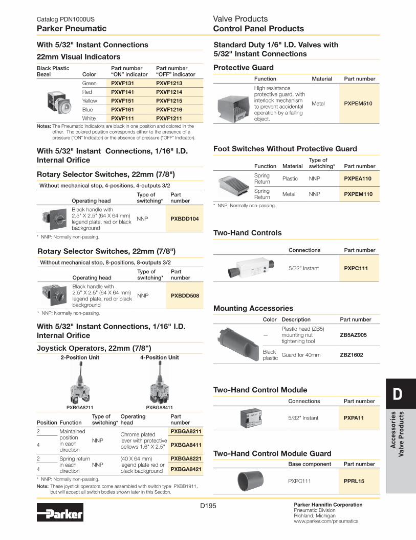
Two-Hand Controls
Connections Part number
5/32” Instant PXPC111
Valve ProductsControl Panel Products
With 5/32" Instant Connections
Notes: The Pneumatic Indicators are black in one position and colored in the other. The colored position corresponds either to the presence of a pressure (“ON” Indicator) or the absence of pressure (“OFF” Indicator).
22mm Visual IndicatorsBlack Plastic Bezel Color
Part number“ON” indicator
Part number“OFF” indicator
Green PXVF131 PXVF1213
Red PXVF141 PXVF1214
Yellow PXVF151 PXVF1215
Blue PXVF161 PXVF1216
White PXVF111 PXVF1211
With 5/32" Instant Connections, 1/16" I.D. Internal Orifice
2-Position Unit 4-Position Unit
Note: These joystick operators come assembled with switch type PXBB1911, but will accept all switch bodies shown later in this Section.
Joystick Operators, 22mm (7/8")
Position FunctionType ofswitching*
Operatinghead
Part number
2 Maintained position in each direction
NNPChrome plated lever with protective bellows 1.6" X 2.5"
PXBGA8211
4 PXBGA8411
2 Spring return in each direction
NNP(40 X 64 mm) legend plate red or black background
PXBGA8221
4 PXBGA8421
* NNP: Normally non-passing.
* NNP: Normally non-passing.
* NNP: Normally non-passing.
* NNP: Normally non-passing.
With 5/32" Instant Connections, 1/16" I.D. Internal Orifice
Rotary Selector Switches, 22mm (7/8")Without mechanical stop, 4-positions, 4-outputs 3/2
Operating headType of switching*
Part number
Black handle with 2.5" X 2.5" (64 X 64 mm) legend plate, red or black background
NNP PXBDD104
Rotary Selector Switches, 22mm (7/8")Without mechanical stop, 8-positions, 8-outputs 3/2
Operating headType of switching*
Part number
Black handle with 2.5" X 2.5" (64 X 64 mm) legend plate, red or black background
NNP PXBDD508
PXBGA8411PXBGA8211
Standard Duty 1/6" I.D. Valves with 5/32" Instant Connections
Foot Switches Without Protective Guard
Function MaterialType ofswitching* Part number
Spring Return Plastic NNP PXPEA110
Spring Return Metal NNP PXPEM110
Protective GuardFunction Material Part number
High resistance protective guard, with interlock mechanism to prevent accidental operation by a falling object.
Metal PXPEM510
Mounting AccessoriesColor Description Part number
—Plastic head (ZB5) mounting nut tightening tool
ZB5AZ905
Black plastic Guard for 40mm ZBZ1602
Two-Hand Control ModuleConnections Part number
5/32" Instant PXPA11
Two-Hand Control Module GuardBase component Part number
PXPC111 PPRL15

Catalog PDN1000US
Parker Pneumatic
Parker Hannifin CorporationPneumatic DivisionRichland, Michiganwww.parker.com/pneumatics
D196
DA
ccessories Valve P
roducts
3/2 Miniature Direct Acting Limit Switches 1/16" I.D. Internal Orifice
ActuatorType ofswitching*
Flow SCFM (NI/min) Nominal bore Connection
Partnumber
Steel plunger operating levers available NNP 2.2 (60)
1/16" (1.5mm)
5/32" instant PXCM111
10-32 UNF PXCM115
Plastic roller NNP 3.0 (85)5/32" instant PXCM121
10-32 UNF PXCM125
7/64" I.D. Internal Orifice
Plastic roller NNP 5/32" instant PXCM521
Actuators For Steel Plunger (Use with PXCM11*)
Plastic roller lever PXCZ11
Plastic roller lever, one way trip PXCZ12
3/2 Compact Pilot Operated Limit Switches 7/64" I.D. Internal Orifice, 5/32" Instant Connections, Pipeable Exhaust Port
ActuatorType ofswitching*
Flow SCFM (NI/min) Nominal bore Connection
Partnumber
Steel plunger operating levers available
NNP 8.8 (250) 7/64" (2.5mm) 5/32" instant
PXCM601A110
Steel roller plunger PXCM601A102
90° Steel roller plunger PXCM601A103
Operating information Operating pressure: 40 to 115 PSIG (3 to 8 bar)
Operating temperature: Operating 32°F to 122°F (0°C to 50°C) Storage -22°F to 140°F (-30°C to 60°C)
Valve ProductsSensing
MaterialsBody Zinc Alloy
Poppets Polyurethane
Seals Nitrile (Buna N)
To achieve the sensing or feedback function, pneumatic sensors can be:
• Limit switches in a variety of sizes and configurations• Pressure switches with many adjustable ranges• Components designed specifically for pneumatic technology
using pressure variation, air bleed or blocking for detection.A wide variety of pneumatic sensors are available to suit any application requirement.
Most popular. For technical information see CD
* NNP: Normally non-passing.

Catalog PDN1000US
Parker Pneumatic
Parker Hannifin CorporationPneumatic DivisionRichland, Michiganwww.parker.com/pneumatics
D197
DA
cces
sori
es
Valv
e P
rodu
cts
Plunger Operated Limit Switches 1/8" I.D. Internal Orifice, 5/32" Instant Connections, Pipeable Exhaust Port
ActuatorType ofswitching*
Flow SCFM (NI/min) Nominal bore Connection
Partnumber
Steel plungerNNP
7.4 (210) 1/8" (3mm) 5/32" instant
PXCK21101
NP PXCK22101
Steel roller plunger
NNP PXCK21102
NP PXCK22102
Plastic roller plunger
NNP PXCK21121
NP PXCK22121
Cats whisker
NNP PXCK21106
NP PXCK22106
Roller Operated Limit Switches 1/8" I.D. Internal Orifice, 5/32" Instant Connections, Pipeable Exhaust Port
ActuatorType ofswitching*
Flow SCFM (NI/min) Nominal bore Connection
Partnumber
Fixed delrin roller lever multi-function head actuates: - from right and left - from right - from left
NNP
7.4 (210) 1/8" (3mm) 5/32" instant
PXCK2110031
NP PXCK2210031
Adjustable delrin roller lever multi-function head actuates: - from right and left - from right - from left
NNP PXCK2110041
NP PXCK2210041
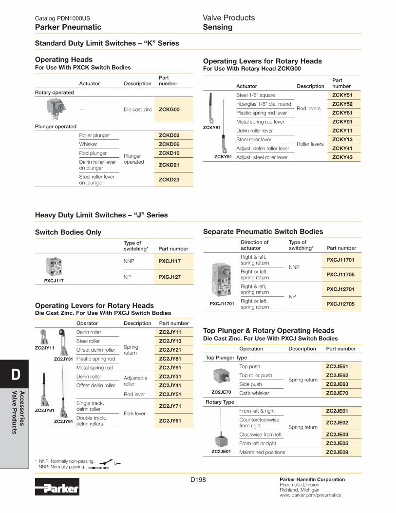
Valve ProductsSensing
Standard Duty Limit Switches – “K” Series
Separate Pneumatic Switch Bodies
ActuatorType of switching* Part number
For use with ZCK series operating heads
NNP PXCK211
NP PXCK221
Pneumatic Switch Bodies with Rotary Heads
ActuatorType of switching* Part number
Multi-function head actuates: - from right and left - from right - from left
NNP PXCK21100
NP PXCK22100
* NNP: Normally non-passing. NNP: Normally passing.
Catalog PDN1000US
Parker Pneumatic
Parker Hannifin CorporationPneumatic DivisionRichland, Michiganwww.parker.com/pneumatics
D198
DA
ccessories Valve P
roducts
Operating Levers for Rotary Heads Die Cast Zinc. For Use With PXCJ Switch Bodies
Operator Description Part number
Delrin roller
Spring return
ZC2JY11
Steel roller ZC2JY13
Offset delrin roller ZC2JY21
Plastic spring rod ZC2JY81
Metal spring rod ZC2JY91
Delrin roller Adjustable roller
ZC2JY31
Offset delrin roller ZC2JY41
Rod lever ZC2JY51
Single track, delrin roller
Fork leverZC2JY71
Double track, delrin rollers ZC2JY61
Operating Levers for Rotary Heads For Use With Rotary Head ZCKG00
Actuator DescriptionPart number
Steel 1/8" square
Rod levers
ZCKY51
Fiberglas 1/8" dia. round ZCKY52
Plastic spring rod lever ZCKY81
Metal spring rod lever ZCKY91
Delrin roller lever
Roller levers
ZCKY11
Steel roller lever ZCKY13
Adjust. delrin roller lever ZCKY41
Adjust. steel roller lever ZCKY43
Valve ProductsSensing
Standard Duty Limit Switches – “K” Series
Heavy Duty Limit Switches – “J” Series
Operating Heads For Use With PXCK Switch Bodies
Actuator DescriptionPart number
Rotary operated
— Die cast zinc ZCKG00
Plunger operated
Roller plunger
Plunger operated
ZCKD02
Whisker ZCKD06
Rod plunger ZCKD10
Delrin roller lever on plunger ZCKD21
Steel roller lever on plunger ZCKD23
Separate Pneumatic Switch BodiesDirection of actuator
Type of switching* Part number
Right & left, spring return
NNPPXCJ11701
Right or left, spring return PXCJ11705
Right & left, spring return
NPPXCJ12701
Right or left, spring return PXCJ12705
Switch Bodies OnlyType of switching* Part number
NNP PXCJ117
NP PXCJ127
* NNP: Normally non-passing. NNP: Normally passing.
ZCKY81
ZCKY91
Top Plunger & Rotary Operating Heads Die Cast Zinc. For Use With PXCJ Switch Bodies
Operation Description Part number
Top Plunger Type
Top push
Spring return
ZC2JE61
Top roller push ZC2JE62
Side push ZC2JE63
Cat’s whisker ZC2JE70
Rotary Type
From left & right
Spring return
ZC2JE01
Counterclockwise from right ZC2JE02
Clockwise from left ZC2JE03
From left or right ZC2JE05
Maintained positions ZC2JE09
PXCJ11701
PXCJ117
ZC2JY11
ZC2JY81
ZC2JY31
ZC2JE70
ZC2JE01
ZC2JY91

Catalog PDN1000US
Parker Pneumatic
Parker Hannifin CorporationPneumatic DivisionRichland, Michiganwww.parker.com/pneumatics
D199
DA
cces
sori
es
Valv
e P
rodu
cts
Valve ProductsSensing – Blocking Valves
The blocking valve is a single acting spring return 2/2 valve in a fitting format. The device requires a pneumatic pilot signal to open, which allows free flow of air, gas or liquid to pass. As long as a pilot signal is present, the device will remain open. When the pilot signal is removed, the internal spring will close the blocking valve, bubble tight. The blocking valve is oil serviceable and rated to 150 PSI.
These devices have two primary design uses: (1) to prevent unwanted gravity induced motion in cylinders during shut down procedures or during periods of lost supply pressure and (2) freezing the cylinder position by using a blocking valve at each end of the cylinder. Application needs such as tool or work piece protection, horizontal indexing or inspection stops are often satisfied by these devices.
For Cylinder Mounting (Can also be mounted in Threshold Sensor Banjo)
With Instant Tube FittingsBSPP NPT
SymbolConnectionfor pilot
Cylinderport thread(male)
Connectionfor tube Part number
Connectionfor pilot
Cylinderport thread(male)
Connectionfor tube Part number
4mm Tube
1/8" 6mm PWBA1468
5/32" Tube
1/8" 1/4" PWBA3468
1/4" 6mm PWBA1469 1/4" 1/4" PWBA3469
1/4" 8mm PWBA1489 3/8" 3/8" PWBA3493
3/8" 8mm PWBA1483 1/2" 1/2" PWBA3412
3/8" 10mm PWBA1493
1/2" 12mm PWBA1412
With Threaded Connections and Tube Pilot PortBSPP NPT
SymbolConnectionfor pilot
Cylinder port thread(male)
Connection from valve (female) Part number
Connectionfor pilot
Cylinder port thread(male)
Connection from valve (female) Part number
4mm Tube
1/8" 1/4" PWBA1898
5/32" * Tube
1/8" 1/8" PWBA3888
1/4" 1/4" PWBA1899 1/4" 1/4" PWBA3899
M5 Female
3/8" 3/8" PWBA1833 3/8" 3/8" PWBA3833
1/2" 1/2" PWBA1822 1/2" 1/2" PWBA3822* Instant fitting
With Threaded Connections and Threaded Pilot Port NPT
Connectionfor pilot
Cylinderport thread(male)
Connectionfrom valve Part number
1/8" pipe
1/8" 1/8" PWBA38887
1/4" 1/4" PWBA38997
3/8" 3/8" PWBA38337
1/2" 1/2" PWBA38227
PWBA3469
PWBA3833
Operating information Operating pressure: 0 to 150 PSIG (0 to 10.3 bar)
Operating temperature: Operating 5°F to 140°F (-15°C to 60°C) Storage -40°F to 160°F (-40°C to 70°C)
MaterialsBody Zinc alloy
Catalog PDN1000US
Parker Pneumatic
Parker Hannifin CorporationPneumatic DivisionRichland, Michiganwww.parker.com/pneumatics
D200
DA
ccessories Valve P
roducts
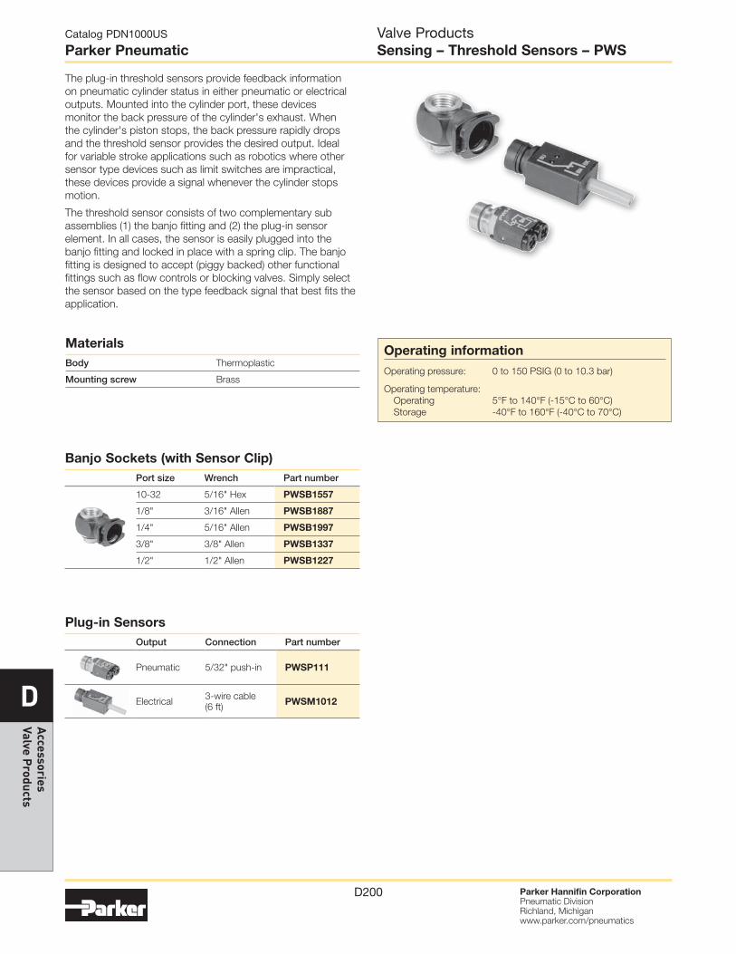
Valve ProductsSensing – Threshold Sensors – PWS
Operating information Operating pressure: 0 to 150 PSIG (0 to 10.3 bar)
Operating temperature: Operating 5°F to 140°F (-15°C to 60°C) Storage -40°F to 160°F (-40°C to 70°C)
MaterialsBody Thermoplastic
Mounting screw Brass
The plug-in threshold sensors provide feedback information on pneumatic cylinder status in either pneumatic or electrical outputs. Mounted into the cylinder port, these devices monitor the back pressure of the cylinder's exhaust. When the cylinder's piston stops, the back pressure rapidly drops and the threshold sensor provides the desired output. Ideal for variable stroke applications such as robotics where other sensor type devices such as limit switches are impractical, these devices provide a signal whenever the cylinder stops motion.
The threshold sensor consists of two complementary sub assemblies (1) the banjo fitting and (2) the plug-in sensor element. In all cases, the sensor is easily plugged into the banjo fitting and locked in place with a spring clip. The banjo fitting is designed to accept (piggy backed) other functional fittings such as flow controls or blocking valves. Simply select the sensor based on the type feedback signal that best fits the application.
Banjo Sockets (with Sensor Clip)Port size Wrench Part number
10-32 5/16" Hex PWSB1557
1/8" 3/16" Allen PWSB1887
1/4" 5/16" Allen PWSB1997
3/8" 3/8" Allen PWSB1337
1/2" 1/2" Allen PWSB1227
Plug-in SensorsOutput Connection Part number
Pneumatic 5/32" push-in PWSP111
Electrical 3-wire cable (6 ft) PWSM1012

Catalog PDN1000US
Parker Pneumatic
Parker Hannifin CorporationPneumatic DivisionRichland, Michiganwww.parker.com/pneumatics
D201
DA
cces
sori
es
Valv
e P
rodu
cts
Valve ProductsSensing Dimensions
Miniature Limit Switches
Compact Limit Switches
PXCM121, PXCM131 PXCM521
.41(10.5).87
(22.2).14
(3.5)1.14(29)
.80(20.2) 2 x .13 (3.2) dia.
Max
. Str
oke
.06
(1.4
)
Fun
ct. S
trok
e .0
4 (0
.9)
96(24.5)
.21 (5.4)
.41(10.3)
1.38(35)
.12(3)
Ø.31(8)
.94(24)
1.38(35)
.16(4)Ø.30
(10).75(19)
.59(15)
.26(7)
.69(17.5)
Ø .55 (14)
.79(20)
.16(4)
1.10(28)
2x Ø .17 (4.2)
Fu
nct
. str
oke
.0
8 (
2)
Ma
x. s
tro
ke .
13
(3
.2)
1.61(41)
.96 to 1.10(25 to 28)
Fun
ct. s
trok
e .0
9 (2
.2)
Max
. str
oke
.23
(5.8
)
.59(15)
.26(7)
.91(23)
.79(20)
.35(9)
1.34(34)
2.05(52)
1.06(27)
2x Ø .17 (4.2)
Ø .55 (14)
PXCM111 PXCZ12 PXCZ11
PXCM601A110
.16(4)
G
.63(16)
1.18(30)
ØØ.47(12)
1.93(49)
2.76(70)
1.46(37)
1.18(30)
.79(20)
.16(4)
G
.63(16)
1.18(30)
Ø Ø.47(12)
1.93(49)
2.76(70)
1.46(37)
1.18(30)
.79(20)
G
.63(16)
1.18(30)
ØØ
.47(12) Ø
.32(8)
1.93(49)
2.23(57)1.46
(37)
.77(19.5)
.79(20)
Ø: 2 mounting holes Ø .17" (4.3) 2 countersunk Ø .32" (8.2) depth 4 mm
G: top mounting holes, 2 x M5 .71" (18 mm) centers
PXCM601A102 PXCM601A103
Catalog PDN1000US
Parker Pneumatic
Parker Hannifin CorporationPneumatic DivisionRichland, Michiganwww.parker.com/pneumatics
D202
DA
ccessories Valve P
roducts
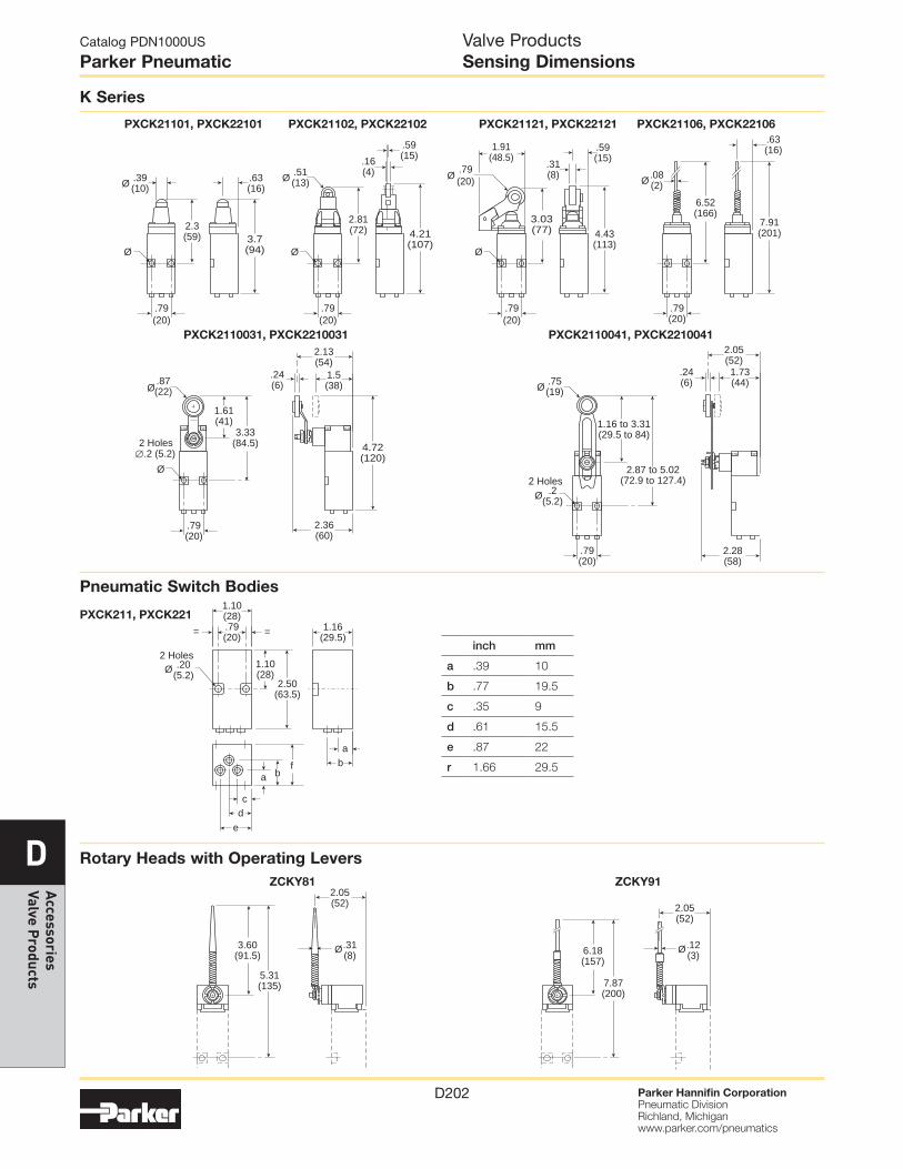
Valve ProductsSensing Dimensions
K Series
1.16(29.5)
2 HolesØ .20
(5.2)
.79(20) ==
1.10(28)
1.10(28)
2.50(63.5)
ab
cd
e
a bf
5.31(135)
3.60(91.5)
2.05 (52)
7.87 (200)
6.18 (157)
Ø.31 (8)
2.05 (52)
Ø.12 (3)
Rotary Heads with Operating Levers
Pneumatic Switch Bodies
PXCK211, PXCK221
ZCKY81 ZCKY91
3.7(94)
.59(15)
.51(13)
4.21(107)
.16(4)
.59(15)
.31(8)
3.03(77)
1.91(48.5)
Ø
Ø
Ø .08(2)
.63(16)
.63(16)
2.3(59)
2.81(72) 4.43
(113)
.79(20)
.79(20)
.79(20)
7.91(201)
6.52(166)
Ø
.79(20)
Ø
.79(20)
Ø.39(10)Ø
PXCK21101, PXCK22101 PXCK21102, PXCK22102 PXCK21121, PXCK22121 PXCK21106, PXCK22106
∅
2.36(60)
4.72(120)
.24(6)
1.5(38)
2.13(54)
.87(22)
2 Holes.2 (5.2)
1.61(41)
3.33(84.5)
Ø
.79(20)
Ø
1.73(44)
.24(6)
2.05 (52)
.75(19)
2.87 to 5.02(72.9 to 127.4)
1.16 to 3.31(29.5 to 84)
2 Holes.2
(5.2)
2.28(58)
Ø
Ø
.79(20)
PXCK2110031, PXCK2210031 PXCK2110041, PXCK2210041
inch mm
a .39 10
b .77 19.5
c .35 9
d .61 15.5
e .87 22
r 1.66 29.5
Catalog PDN1000US
Parker Pneumatic
Parker Hannifin CorporationPneumatic DivisionRichland, Michiganwww.parker.com/pneumatics
D203
DA
cces
sori
es
Valv
e P
rodu
cts
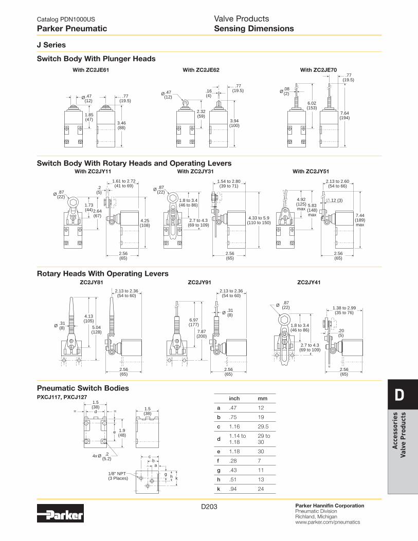
Valve ProductsSensing Dimensions
J Series
.2(5)
1.61 to 2.72(41 to 69)
1.54 to 2.80(39 to 71)
2.56(65)
2.56(65)
2.56(65)
Ø .87(22)
Ø .87(22)
2.13 to 2.60(54 to 66)
.12 (3)5.83(148)max
4.92(125)max
7.44(189)max
1.8 to 3.4(46 to 86)
2.7 to 4.3(69 to 109)
4.33 to 5.9(110 to 150)
1.73(44)2.64
(67)4.25(108)
Switch Body With Rotary Heads and Operating Levers
2.13 to 2.36(54 to 60)
2.56(65)
2.56(65)
2.56(65)
2.13 to 2.36(54 to 60)
Ø .31(8)
Ø .31(8)
Ø .87(22) 1.38 to 2.99
(35 to 76)
.20(5)
4.13(105)
5.04(128)
6.97(177)
7.87(200)
1.8 to 3.4(46 to 86)
2.7 to 4.3(69 to 109)
.77(19.5)
.77(19.5)
.77(19.5)
3.46(88)
Ø.47(12)
Ø.47(12)
1.85(47)
.16(4)
3.94(100)
2.32(59)
7.64(194)
6.02(153)
Ø.08(2)
Switch Body With Plunger Heads
Rotary Heads With Operating Levers
Pneumatic Switch Bodies
ZC2JY81 ZC2JY91 ZC2JY41
With ZC2JE61 With ZC2JE62 With ZC2JE70
= =
4x
1/8" NPT(3 Places)
Ø .2(5.2)
ab
c
d
e
f
g h k
1.5(38) 1.5
(38)
1.9(48)
With ZC2JY11 With ZC2JY31 With ZC2JY51
inch mm
a .47 12
b .75 19
c 1.16 29.5
d 1.14 to 1.18
29 to 30
e 1.18 30
f .28 7
g .43 11
h .51 13
k .94 24
PXCJ117, PXCJ127

Catalog PDN1000US
Parker Pneumatic
Parker Hannifin CorporationPneumatic DivisionRichland, Michiganwww.parker.com/pneumatics
D204
DA
ccessories Valve P
roducts
Valve ProductsSensing Dimensions
Blocking Valves
Threshold Sensors
∅A
H
K
B
L
C
∅A
H
K
B
L
C
∅A
H
K
B
L
C
1/8" NPT
C
PWBA14/34
PWBA18/38
PWBA38
ØA B C K H L Flow* Part number
0.86" (22) 0.82" (21) 0.94" (24) 0.53" (13.5) 2.32" (59) 1.54" (39) 14.8 PWBA1468/3468
0.86" (22) 0.82" (21) 0.94" (24) 0.53" (13.5) 2.09" (53) 1.54" (39) 19.4 PWBA1469/3469PWBA1489
1.06""(27) 1.10" (28) 0.94" (24) 0.55" (14) 2.09" (53) 1.98" (50) 45.9 PWBA1483PWBA1493/3493
1.22" (31) 1.30" (33) 1.30" (33) 0.94" (24) 2.59" (66) 2.59" (66) 81.2 PWBA1412/3412
0.86" (22) 0.82" (21) 0.94" (24) 0.53" (13.5) 2.32" (59) 1.71" (43.5) 14.8 PWBA1898/3888
0.86" (22) 0.82" (21) 0.94" (24) 0.53" (13.5) 2.09" (53) 1.71" (43.5) 19.4 PWBA1899/3899
1.06" (27) 1.10" (28) 0.94" (24) 0.55" (14) 2.09" (53) 2.18" (55) 45.9 PWBA1833/3833
1.22" (31) 1.30" (33) 1.30" (33) 0.94" (24) 2.59" (66) 2.47" (63) 81.2 PWBA1822/3822
0.75" (19) 0.87" (22) 0.83" (21) 0.67" (17) 2.20" (56) 1.73" (44) 14.8 PWBA38887
0.75" (19) 0.87" (22) 0.83" (21) 0.67" (17) 2.20" (56) 1.73" (44) 19.4 PWBA38997
1.06" (27) 1.18" (30) 1.06" (27) 0.91" (23) 2.64" (67) 1.42" (36) 45.9 PWBA38337
1.06" (27) 1.18" (30) 1.06" (27) 0.91" (23) 2.64" (67) 1.42" (36) 81.2 PWBA38227
PWSP111
Banjo Socket A B C H K L Part number
.98 (25) .43 (11) 5/16" Hex .79 (20) .40 (10) .67 (17) PWSB1557
.98 (25) .63 (16) 3/16" Allen .71 (18) .40 (10) .79 (20) PWSB1887
.98 (25) .83 (21) 5/16" Allen .71 (18) .40 (10) .87 (22) PWSB1997
.98 (25) 1.10 (28) 3/8" Allen .79 (20) .47 (12) .98 (25) PWSB1337
.98 (25) 1.30 (33) 1/2" Allen .93 (24) .55 (14) 1.02 (26) PWSB1227
HK
C
B
LB/2
A
.87(22)
.79(20)
18 x 24
1.26(32)
.79(20)
PWSM1012

ParkerHannifinCorporationPneumatic DivisionRichland, Michiganwww.parker.com/pneumatics
G5
G
Safe
ty G
uide
, O
ffer
of S
ale
Safety Guide For Selecting And Using Pneumatic Division Products And Related Accessories
WARNING:FAILURE OR IMPROPER SELECTION OR IMPROPER USE OF PNEUMATIC DIVISION PRODUCTS, ASSEMBLIES OR RELATED ITEMS (“PRODUCTS”) CAN CAUSE DEATH, PERSONAL INJURY, AND PROPERTY DAMAGE. POSSIBLE CONSEQUENCES OF FAILURE OR IMPROPER SELECTION OR IMPROPER USE OF THESE PRODUCTS INCLUDE BUT ARE NOT LIMITED TO:• Unintended or mistimed cycling or motion of machine members or failure to cycle
• Work pieces or component parts being thrown off at high speeds.
• Failure of a device to function properly for example, failure to clamp or unclamp an associated item or device.
• Explosion
• Suddenly moving or falling objects.
• Release of toxic or otherwise injurious liquids or gasses.
Before selecting or using any of these Products, it is important that you read and follow the instructions below.
!
Pneumatic ProductsSafety Guide, Control Products
1. GENERAL INSTRUCTIONS 1.1. Scope: This safety guide is designed to cover general guidelines on the installation, use, and maintenance of Pneumatic Division
Valves, FRLs (Filters, Pressure Regulators, and Lubricators), Vacuum products and related accessory components. 1.2. Fail-Safe: Valves, FRLs, Vacuum products and their related components can and do fail without warning for many reasons. Design all
systems and equipment in a fail-safe mode, so that failure of associated valves, FRLs or Vacuum products will not endanger persons or property.
1.3 Relevant International Standards: For a good guide to the application of a broad spectrum of pneumatic fluid power devices see: ISO 4414:1998, Pneumatic Fluid Power – General Rules Relating to Systems. See www.iso.org for ordering information.
1.4. Distribution: Provide a copy of this safety guide to each person that is responsible for selection, installation, or use of Valves, FRLs or Vacuum products. Do not select, or use Parker valves, FRLs or vacuum products without thoroughly reading and understanding this safety guide as well as the specific Parker publications for the products considered or selected.
1.5. User Responsibility: Due to the wide variety of operating conditions and applications for valves, FRLs, and vacuum products Parker and its distributors do not represent or warrant that any particular valve, FRL or vacuum product is suitable for any specific end use system. This safety guide does not analyze all technical parameters that must be considered in selecting a product. The user, through its own analysis and testing, is solely responsible for: • Making the final selection of the appropriate valve, FRL, Vacuum component, or accessory.
• Assuring that all user’s performance, endurance, maintenance, safety, and warning requirements are met and that the application presents no health or safety hazards.
• Complying with all existing warning labels and / or providing all appropriate health and safety warnings on the equipment on which the valves, FRLs or Vacuum products are used; and,
• Assuring compliance with all applicable government and industry standards. 1.6. Safety Devices: Safety devices should not be removed, or defeated. 1.7. Warning Labels: Warning labels should not be removed, painted over or otherwise obscured. 1.8. Additional Questions: Call the appropriate Parker technical service department if you have any questions or require any additional
information. See the Parker publication for the product being considered or used, or call 1-800-CPARKER, or go to www.parker.com, for telephone numbers of the appropriate technical service department.
2. PRODUCT SELECTION INSTRUCTIONS 2.1. Flow Rate: The flow rate requirements of a system are frequently the primary consideration when designing any pneumatic system.
System components need to be able to provide adequate flow and pressure for the desired application. 2.2. Pressure Rating: Never exceed the rated pressure of a product. Consult product labeling, Pneumatic Division catalogs or the
instruction sheets supplied for maximum pressure ratings. 2.3. Temperature Rating: Never exceed the temperature rating of a product. Excessive heat can shorten the life expectancy of a product
and result in complete product failure. 2.4. Environment: Many environmental conditions can affect the integrity and suitability of a product for a given application. Pneumatic
Division products are designed for use in general purpose industrial applications. If these products are to be used in unusual circumstances such as direct sunlight and/or corrosive or caustic environments, such use can shorten the useful life and lead to premature failure of a product.
2.5. Lubrication and Compressor Carryover: Some modern synthetic oils can and will attack nitrile seals. If there is any possibility of synthetic oils or greases migrating into the pneumatic components check for compatibility with the seal materials used. Consult the factory or product literature for materials of construction.
2.6. Polycarbonate Bowls and Sight Glasses: To avoid potential polycarbonate bowl failures: • Do not locate polycarbonate bowls or sight glasses in areas where they could be subject to direct sunlight, impact blow, or temperatures outside of the rated range.
• Do not expose or clean polycarbonate bowls with detergents, chlorinated hydro-carbons, keytones, esters or certain alcohols. • Do not use polycarbonate bowls or sight glasses in air systems where compressors are lubricated with fire resistant fluids such as
phosphate ester and di-ester lubricants.
Catalog PDN1000US
ParkerPneumatics

ParkerHannifinCorporationPneumatic DivisionRichland, Michiganwww.parker.com/pneumatics
G6
G
Safety Guide,
Offer of Sale
2.7. Chemical Compatibility: For more information on plastic component chemical compatibility see Pneumatic Division technical bulletins Tec-3, Tec-4, and Tec-5
2.8. Product Rupture: Product rupture can cause death, serious personal injury, and property damage. • Do not connect pressure regulators or other Pneumatic Division products to bottled gas cylinders.
• Do not exceed the maximum primary pressure rating of any pressure regulator or any system component. • Consult product labeling or product literature for pressure rating limitations.3. PRODUCT ASSEMBLY AND INSTALLATION INSTRUCTIONS 3.1. Component Inspection: Prior to assembly or installation a careful examination of the valves, FRLs or vacuum products must be
performed. All components must be checked for correct style, size, and catalog number. DO NOT use any component that displays any signs of nonconformance.
3.2. Installation Instructions: Parker published Installation Instructions must be followed for installation of Parker valves, FRLs and vacuum components. These instructions are provided with every Parker valve or FRL sold, or by calling 1-800-CPARKER, or at www.parker.com.
3.3. Air Supply: The air supply or control medium supplied to Valves, FRLs and Vacuum components must be moisture-free if ambient temperature can drop below freezing
4. VALVE AND FRL MAINTENANCE AND REPLACEMENT INSTRUCTIONS 4.1. Maintenance: Even with proper selection and installation, valve, FRL and vacuum products service life may be significantly reduced
without a continuing maintenance program. The severity of the application, risk potential from a component failure, and experience with any known failures in the application or in similar applications should determine the frequency of inspections and the servicing or replacement of Pneumatic Division products so that products are replaced before any failure occurs. A maintenance program must be established and followed by the user and, at minimum, must include instructions 4.2 through 4.10.
4.2. Installation and Service Instructions: Before attempting to service or replace any worn or damaged parts consult the appropriate Service Bulletin for the valve or FRL in question for the appropriate practices to service the unit in question. These Service and Installation Instructions are provided with every Parker valve and FRL sold, or are available by calling 1-800-CPARKER, or by accessing the Parker web site at www.parker.com.
4.3. Lockout / Tagout Procedures: Be sure to follow all required lockout and tagout procedures when servicing equipment. For more information see: OSHA Standard – 29 CFR, Part 1910.147, Appendix A, The Control of Hazardous Energy – (Lockout / Tagout)
4.4. Visual Inspection: Any of the following conditions requires immediate system shut down and replacement of worn or damaged components: • Air leakage: Look and listen to see if there are any signs of visual damage to any of the components in the system. Leakage is an indication of worn or damaged components.
• Damaged or degraded components: Look to see if there are any visible signs of wear or component degradation. • Kinked, crushed, or damaged hoses. Kinked hoses can result in restricted air flow and lead to unpredictable system behavior. • Any observed improper system or component function: Immediately shut down the system and correct malfunction. • Excessive dirt build-up: Dirt and clutter can mask potentially hazardous situations. Caution: Leak detection solutions should be rinsed off after use. 4.5. Routine Maintenance Issues:
• Remove excessive dirt, grime and clutter from work areas. • Make sure all required guards and shields are in place. 4.6. Functional Test: Before initiating automatic operation, operate the system manually to make sure all required functions operate
properly and safely. 4.7. Service or Replacement Intervals: It is the user’s responsibility to establish appropriate service intervals. Valves, FRLs and vacuum
products contain components that age, harden, wear, and otherwise deteriorate over time. Environmental conditions can significantly accelerate this process. Valves, FRLs and vacuum components need to be serviced or replaced on routine intervals. Service intervals need to be established based on: • Previous performance experiences.
• Government and / or industrial standards. • When failures could result in unacceptable down time, equipment damage or personal injury risk. 4.8. Servicing or Replacing of any Worn or Damaged Parts: To avoid unpredictable system behavior that can cause death, personal
injury and property damage: • Follow all government, state and local safety and servicing practices prior to service including but not limited to all OSHA Lockout Tagout procedures (OSHA Standard – 29 CFR, Part 1910.147, Appendix A, The Control of Hazardous Energy – Lockout / Tagout).
• Disconnect electrical supply (when necessary) before installation, servicing, or conversion. • Disconnect air supply and depressurize all air lines connected to system and Pneumatic Division products before installation, service,
or conversion. • Installation, servicing, and / or conversion of these products must be performed by knowledgeable personnel who understand how
pneumatic products are to be applied. • After installation, servicing, or conversions air and electrical supplies (when necessary) should be connected and the product tested
for proper function and leakage. If audible leakage is present, or if the product does not operate properly, do not put product or system into use.
• Warnings and specifications on the product should not be covered or painted over. If masking is not possible, contact your local representative for replacement labels.
4.9. Putting Serviced System Back into Operation: Follow the guidelines above and all relevant Installation and Maintenance Instructions supplied with the valve FRL or vacuum component to insure proper function of the system.
Pneumatic ProductsSafety Guide, Control Products
Catalog PDN1000US
ParkerPneumatics

ParkerHannifinCorporationPneumatic DivisionRichland, Michiganwww.parker.com/pneumatics
G7
G
Safe
ty G
uide
, O
ffer
of S
ale
1. TermsandConditions. Seller’s willingness to offer Products, or accept an order for Products, to or from Buyer is expressly conditioned on Buyer’s assent to these Terms and Conditions and to the terms and conditions found on-line at www.parker.com/saleterms/. Seller objects to any contrary or additional term or condition of Buyer’s order or any other document issued by Buyer.2. Price Adjustments; Payments. Prices stated on the reverse side or preceding pages of this document are valid for 30 days. After 30 days, Seller may change prices to reflect any increase in its costs resulting from state, federal or local legislation, price increases from its suppliers, or any change in the rate, charge, or classification of any carrier. The prices stated on the reverse or preceding pages of this document do not include any sales, use, or other taxes unless so stated specifically. Unless otherwise specified by Seller, all prices are F.O.B. Seller's facility, and payment is due 30 days from the date of invoice. After 30 days, Buyer shall pay interest on any unpaid invoices at the rate of 1.5% per month or the maximum allowable rate under applicable law.3. DeliveryDates;TitleandRisk;Shipment. All delivery dates are approximate and Seller shall not be responsible for any damages resulting from any delay. Regardless of the manner of shipment, title to any products and risk of loss or damage shall pass to Buyer upon tender to the carrier at Seller's facility (i.e., when it’s on the truck, it’s yours). Unless otherwise stated, Seller may exercise its judgment in choosing the carrier and means of delivery. No deferment of shipment at Buyers' request beyond the respective dates indicated will be made except on terms that will indemnify, defend and hold Seller harmless against all loss and additional expense. Buyer shall be responsible for any additional shipping charges incurred by Seller due to Buyer’s changes in shipping, product specifications or in accordance with Section 13, herein.4. Warranty. Seller warrants that the Products sold hereunder shall be free from defects in material or workmanship for a period of twelve months from the date of delivery to Buyer or 2,000 hours of normal use, whichever occurs first. This warranty is made only to Buyer and does not extend to anyone to whom Products are sold after purchased from Seller. The prices charged for Seller's products are based upon the exclusive limited warranty stated above, and upon the following disclaimer: dISClAIMeR oFWARRANTy:THISWARRANTYCOMPRISESTHESOLEANDENTIREWARRANTYPERTAININGTOPRODUCTSPROVIDEDHEREUNDER.SELLERDISCLAIMSALLOTHERWARRANTIES,EXPRESSANDIMPLIED,INCLUDINGMERCHANTABILITYANDFITNESSFORAPARTICULARPURPOSE.5. Claims; Commencement of Actions. Buyer shall promptly inspect all Products upon delivery. No claims for shortages will be allowed unless reported to the Seller within 10 days of delivery. No other claims against Seller will be allowed unless asserted in writing within 60 days after delivery or, in the case of an alleged breach of warranty, within 30 days after the date within the warranty period on which the defect is or should have been discovered by Buyer. Any action based upon breach of this agreement or upon any other claim arising out of this sale (other than an action by Seller for any amount due to Seller from Buyer) must be commenced within thirteen months from the date of tender of delivery by Seller or, for a cause of action based upon an alleged breach of warranty, within thirteen months from the date within the warranty period on which the defect is or should have been discovered by Buyer.6. LIMITATIONOFLIABILITY.UPON NOTIFICATION, SELLER WILL, AT ITS OPTION, REPAIR OR REPLACE A DEFECTIVE PRODUCT, OR REFUND THE PURCHASE PRICE. INNOEVENTSHALLSELLERBELIABLETOBUYERFORANYSPECIAL,INDIRECT,INCIDENTALORCONSEQUENTIALDAMAGESARISINGOUTOF,ORASTHERESULTOF,THESALE,DELIVERY,NON-DELIVERY,SERVICING,USEORLOSSOFUSEOFTHEPRODUCTSORANYPARTTHEREOF,ORFORANYCHARGES OR EXPENSES OF ANY NATURE INCURRED WITHOUT SELLER'SWRITTEN CONSENT, EVEN IF SELLER HAS BEEN NEGLIGENT, WHETHER INCONTRACT,TORTOROTHERLEGALTHEORY.INNOEVENTSHALLSELLER'SLIABILITYUNDERANYCLAIMMADEBYBUYEREXCEEDTHEPURCHASEPRICEOFTHEPRODUCTS.7. Contingencies. Seller shall not be liable for any default or delay in performance if caused by circumstances beyond the reasonable control of Seller.8. User Responsibility. The user, through its own analysis and testing, is solely responsible for making the final selection of the system and Product and assuring that all performance, endurance, maintenance, safety and warning requirements of the application are met. The user must analyze all aspects of the application and follow applicable industry standards and Product information. If Seller provides Product or system options, the user is responsible for determining that such data and specifications are suitable and sufficient for all applications and reasonably foreseeable uses of the Products or systems.9. Loss to Buyer's Property. Any designs, tools, patterns, materials, drawings, confidential information or equipment furnished by Buyer or any other items which become Buyer's property, may be considered obsolete and may be destroyed by Seller after two consecutive years have elapsed without Buyer placing an order for the items which are manufactured using such property. Seller shall not be responsible for any loss or damage to such property while it is in Seller's possession or control.10. SpecialTooling. A tooling charge may be imposed for any special tooling, including without limitation, dies, fixtures, molds and patterns, acquired to manufacture Products. Such special tooling shall be and remain Seller's property notwithstanding payment of any charges by Buyer. In no event will Buyer acquire any interest in apparatus belonging to Seller which is utilized in the manufacture of the Products, even if such apparatus has been specially converted or adapted for such manufacture and notwithstanding any charges paid by Buyer. Unless otherwise agreed, Seller shall have the right to alter, discard or otherwise dispose of any special tooling or other property in its sole discretion at any time.
TheitemsdescribedinthisdocumentandotherdocumentsanddescriptionsprovidedbyParkerHannifinCorporation,itssubsidiariesanditsauthorizeddistributors(“Seller”)areherebyofferedforsaleatpricestobeestablishedbySeller.Thisofferanditsacceptancebyanycustomer(“Buyer”)shallbegovernedbyallofthefollowingTermsandConditions.Buyer’sorderforanyitemdescribedinitsdocument,whencommunicatedtoSellerverbally,orinwriting,shallconstituteacceptanceofthisoffer.Allgoodsorworkdescribedwillbereferredtoas“Products”.
11. Buyer's Obligation; Rights of Seller. To secure payment of all sums due or otherwise, Seller shall retain a security interest in the goods delivered and this agreement shall be deemed a Security Agreement under the Uniform Commercial Code. Buyer authorizes Seller as its attorney to execute and file on Buyer's behalf all documents Seller deems necessary to perfect its security interest. Seller shall have a security interest in, and lien upon, any property of Buyer in Seller's possession as security for the payment of any amounts owed to Seller by Buyer.12. Improper use and Indemnity. Buyer shall indemnify, defend, and hold Seller harmless from any claim, liability, damages, lawsuits, and costs (including attorney fees), whether for personal injury, property damage, patent, trademark or copyright infringement or any other claim, brought by or incurred by Buyer, Buyer’s employees, or any other person, arising out of: (a) improper selection, improper application or other misuse of Products purchased by Buyer from Seller; (b) any act or omission, negligent or otherwise, of Buyer; (c) Seller’s use of patterns, plans, drawings, or specifications furnished by Buyer to manufacture Product; or (d) Buyer’s failure to comply with these terms and conditions. Seller shall not indemnify Buyer under any circumstance except as otherwise provided.13. Cancellations and Changes. Orders shall not be subject to cancellation or change by Buyer for any reason, except with Seller's written consent and upon terms that will indemnify, defend and hold Seller harmless against all direct, incidental and consequential loss or damage. Seller may change product features, specifications, designs and availability with notice to Buyer.14. LimitationonAssignment. Buyer may not assign its rights or obligations under this agreement without the prior written consent of Seller.15. Entire Agreement. This agreement contains the entire agreement between the Buyer and Seller and constitutes the final, complete and exclusive expression of the terms of the agreement. All prior or contemporaneous written or oral agreements or negotiations with respect to the subject matter are herein merged.16. Waiver and Severability. Failure to enforce any provision of this agreement will not waive that provision nor will any such failure prejudice Seller’s right to enforce that provision in the future. Invalidation of any provision of this agreement by legislation or other rule of law shall not invalidate any other provision herein. The remaining provisions of this agreement will remain in full force and effect.17. Termination. This agreement may be terminated by Seller for any reason and at any time by giving Buyer thirty (30) days written notice of termination. In addition, Seller may by written notice immediately terminate this agreement for the following: (a) Buyer commits a breach of any provision of this agreement (b) the appointment of a trustee, receiver or custodian for all or any part of Buyer’s property (b) the filing of a petition for relief in bankruptcy of the other Party on its own behalf, or by a third party (c) an assignment for the benefit of creditors, or (d) the dissolution or liquidation of the Buyer.18. GoverningLaw. This agreement and the sale and delivery of all Products hereunder shall be deemed to have taken place in and shall be governed and construed in accordance with the laws of the State of Ohio, as applicable to contracts executed and wholly performed therein and without regard to conflicts of laws principles. Buyer irrevocably agrees and consents to the exclusive jurisdiction and venue of the courts of Cuyahoga County, Ohio with respect to any dispute, controversy or claim arising out of or relating to this agreement. Disputes between the parties shall not be settled by arbitration unless, after a dispute has arisen, both parties expressly agree in writing to arbitrate the dispute.19. IndemnityforInfringementofIntellectualPropertyRights. Seller shall have no liability for infringement of any patents, trademarks, copyrights, trade dress, trade secrets or similar rights except as provided in this Section. Seller will defend and indemnify Buyer against allegations of infringement of U.S. patents, U.S. trademarks, copyrights, trade dress and trade secrets (“Intellectual Property Rights”). Seller will defend at its expense and will pay the cost of any settlement or damages awarded in an action brought against Buyer based on an allegation that a Product sold pursuant to this Agreement infringes the Intellectual Property Rights of a third party. Seller's obligation to defend and indemnify Buyer is contingent on Buyer notifying Seller within ten (10) days after Buyer becomes aware of such allegations of infringement, and Seller having sole control over the defense of any allegations or actions including all negotiations for settlement or compromise. If a Product is subject to a claim that it infringes the Intellectual Property Rights of a third party, Seller may, at its sole expense and option, procure for Buyer the right to continue using the Product, replace or modify the Product so as to make it noninfringing, or offer to accept return of the Product and return the purchase price less a reasonable allowance for depreciation. Notwithstanding the foregoing, Seller shall have no liability for claims of infringement based on information provided by Buyer, or directed to Products delivered hereunder for which the designs are specified in whole or part by Buyer, or infringements resulting from the modification, combination or use in a system of any Product sold hereunder. The foregoing provisions of this Section shall constitute Seller's sole and exclusive liability and Buyer's sole and exclusive remedy for infringement of Intellectual Property Rights.20. Taxes. Unless otherwise indicated, all prices and charges are exclusive of excise, sales, use, property, occupational or like taxes which may be imposed by any taxing authority upon the manufacture, sale or delivery of Products.21. Equal Opportunity Clause. For the performance of government contracts and where dollar value of the Products exceed $10,000, the equal employment opportunity clauses in Executive Order 11246, VEVRAA, and 41 C.F.R. §§ 60-1.4(a), 60-741.5(a), and 60-250.4, are hereby incorporated.
Catalog PDN1000US
ParkerPneumaticsPneumatic ProductsOffer of Sale