partsoperationand maintenancemanual€¦ · dies specification tubing size dies for tong and backup...
TRANSCRIPT

MODELMODELMODELMODELXQXQXQXQ114/114/114/114/6666YYYYBBBBHYDRAULICHYDRAULICHYDRAULICHYDRAULIC POWERPOWERPOWERPOWERTONGTONGTONGTONG
PARTSPARTSPARTSPARTS OPERATIONOPERATIONOPERATIONOPERATIONANDANDANDAND
MAINTENANCEMAINTENANCEMAINTENANCEMAINTENANCEMANUALMANUALMANUALMANUAL

CONTENTSⅠ. SUMMARY………………………………………………………………………………1
Ⅱ. SEPCIFICATION………………………………………………………………………1
Ⅲ . INSTALLATION……………………………………………………………1
Ⅳ. OPERATION……………………………………………………………………………2
Ⅴ. MAINTENANCE & LUBRICATION……………………………………………2
Ⅵ. ORDINARY PROBLEMS AND TROUBLESHOOTING GUIDE………3
Ⅶ. TABLE OF JAWAND DIES………………………………………………………4
Ⅷ. TORQUE CHART………………………………………………………………………4
Ⅸ. TABLE OF PARTS AND DRAWINGS…………………………………………5
Fig.1 Shell…………………………………………………………………………………5
Fig.2 Brake mechanism and reset mechanism………………………………………………6
Fig.3 Idle shaft………………………………………………………………………………7
Fig.4 Hanging rod assembly………………………………………………………………8
Fig.5 Power input shaft……………………………………………………………………9
Fig.6 Shifting mechanism assembly………………………………………………………10
Fig.7 Centralizing mechanism……………………………………………………………11
Fig.8 Tong head assembly………………………………………………………………12
Fig.9 Duplex gear shaft…………………………………………………………………13
Fig.10 Hydraulic motor…………………………………………………………………14
Fig.11 Safety door assembly………………………………………………………………15
Fig.12 Lift assembly……………………………………………………………………16
Fig.13 Backup tong head…………………………………………………………………17
Fig.14 Backup tong tail……………………………………………………………………19
Fig.15 Fore guide rod assembly … …………………………………………………21
Fig.16 Back guide rod assembly …………………………………………………22
Fig.17 Hand control valve………………………………………………………23
Ⅰ.... SUMMARYSUMMARYSUMMARYSUMMARY
Model XQ114/6YB(4 1/2") hydraulic power tong is an open type power tong for the making upand breaking out of tubing in well services. This product has the following features:
1,The tong is made up of master tong and backup tong, the master tong has a high and low geartrain, the tong is compact, light and efficient.
2, The master tong and backup hydraulics operate on valve banks independent of each other.
3,The tong has incorporated a new system of disc brake to hold the jaws to connection moreeffectively.
4,Makeup and breakout are made easy with a simple turn to the reset knob on the tong andbackup.
5,The backup has been supplied with quick coupling hoses and connections for quick and easyinstallation for jobs where you need a backup and the backup can be removed in seconds for jobsthat a backup is not required.
Ⅱ.... SEPCIFICATIONSEPCIFICATIONSEPCIFICATIONSEPCIFICATION
1, Application:Tubing:73mm-114mm (2 7/8"to 4 1/2")
2, High gear rated torque:1.5 kN.m (1106 ft.lbs)
3, Low gear rated torque:6 kN.m (4425 ft.lbs)
4, high gear max rotation speed:85 RPM
5, Low gear max rotation speed:20 RPM
6, Opening of tong head:118 mm
7, Overall dimension (L×W×H):750×500×600 mm
8, Weight:220 kg(485lbs)
9, Rated system pressure:1595 Psi
10, Max oil supply:100 L/ min
Ⅲ.... INSTALLATIONINSTALLATIONINSTALLATIONINSTALLATION
A, Hanging: Connect lift with tong hanging rod and hang the tong on the derrick of workover rig,the hanging point is 15 m above ground and the hanging should be in free condition. The distancebetween the tong center and the center of the well is recommended to be 0.5m. The hangingheight is proper when the backup tong could rightly grip the tubing collar.
B, Level: Adjust the screw (Z6-58)on the tong hanger to level the tong and backup, this should bedone to ensure proper gripping of the jaws.
C, Back guy: Tie one end of back guy on derrick and the other end on back guide seat of powertong, back guy should be capable of bearing a load of 20 KN, when power tong is in make upposition, the back guy should be at right angle to the tong and on the opposite side of operatorwho operates the control handles, this insures a safe operation.
D, Pressure hoses: Connect hoses from the hydraulic power source to the control valve bank ofthe power tong. The inlet and the outlet hoses can’t be misconnected.
1

Ⅳ.... OPERATIONOPERATIONOPERATIONOPERATIONMaking up tubing can be spun first in high gear range, final torques must be done in the low gearrange. A PSI chart is provided to convert PSI to FT.LBS torque.Break out must be started in low gear range, once the joint has been loosened, the final brake outcan be done in the high gear range.1, Make-up:After aligning the opening tong head with the backup, turn the reset knobs of each (Z6-49) and(B6-3) switch the arrow to point the direction of make-up. Locate the tong and backup on to thetubing. The backup should be engaged to lock onto the tubing first.Once the backup jaws have been locked on, commence make up with the tong. After the tubing ismade up, reserve rotation of the tong to align the opening of the tong with the tubing. Once this isaccomplished, reverse the backup to align the opening of the backup to the tubing. The tong canbe moved off the tubing. Confirm proper make up torques required from your tubing supplier.2. Break outAligning the opening tong head with the backup, turn the reset knobs of each(Z6-49) and (B6-3)and switch them to point the direction of break out, then push it towards the tubing. Making thejaws of the tong and the backup line up squarely on tubing. Engage the backup first locking ontothe tubing. Commence break out with the tong. Initial break out should always be done in lowgear range. Once break out is accomplished. The joint may be spun off in high gear. To come offthe couplings reverse the rotation of the tong and backup slowly to align the opening of the tongand backup to the tubing. The tong can now be removed off the tubing.3. Replacing jaws.Tong and backup insert jaws slide into the tong heads easily. When you dismount jaws, turn tonghead firstly, make the stop screw on the jaw set bracket expose from the opening tong head, loosethe stop screw, then you can take out the jaws from the center of tong head. Mounting operationprocedure is just on the contrary .Ⅴ.... MAINTENANCEMAINTENANCEMAINTENANCEMAINTENANCE &&&&LUBRICATIONLUBRICATIONLUBRICATIONLUBRICATIONIt is suggested that a regular maintenance program be established, to assure dependable operationof the tubing tong. The following recommendations concerning cleaning, lubrication, andcleaning will enhance the life expectancy of the tong and assure safety to operating personnel.A, CleaningThe tong should be thoroughly cleaned with a good petroleum base cleaning agent, after each job,prior to storage, it is recommended that periodically the motor and valve assembly be removed,along with the top tong plate, so that guides, rollers and gears can be properly cleaned.B, lubricationA good grade of multipurpose bearing lubricant which is compatible with expected ambienttemperature is recommended along with the following lubrication procedures, at the completionof each job prior to storage.1, All grease fittings should have 2 to 5 shots of grease after each job.2, Rotary gear cam surface should be well greased applying with a rag or a brush.3, Cage plates/rings should be coated with grease both through the grease nipples and coated onthe rings.4, Gears can be greased by removed the side inspection cover plate and apply grease directly tothe gear teeth.
2
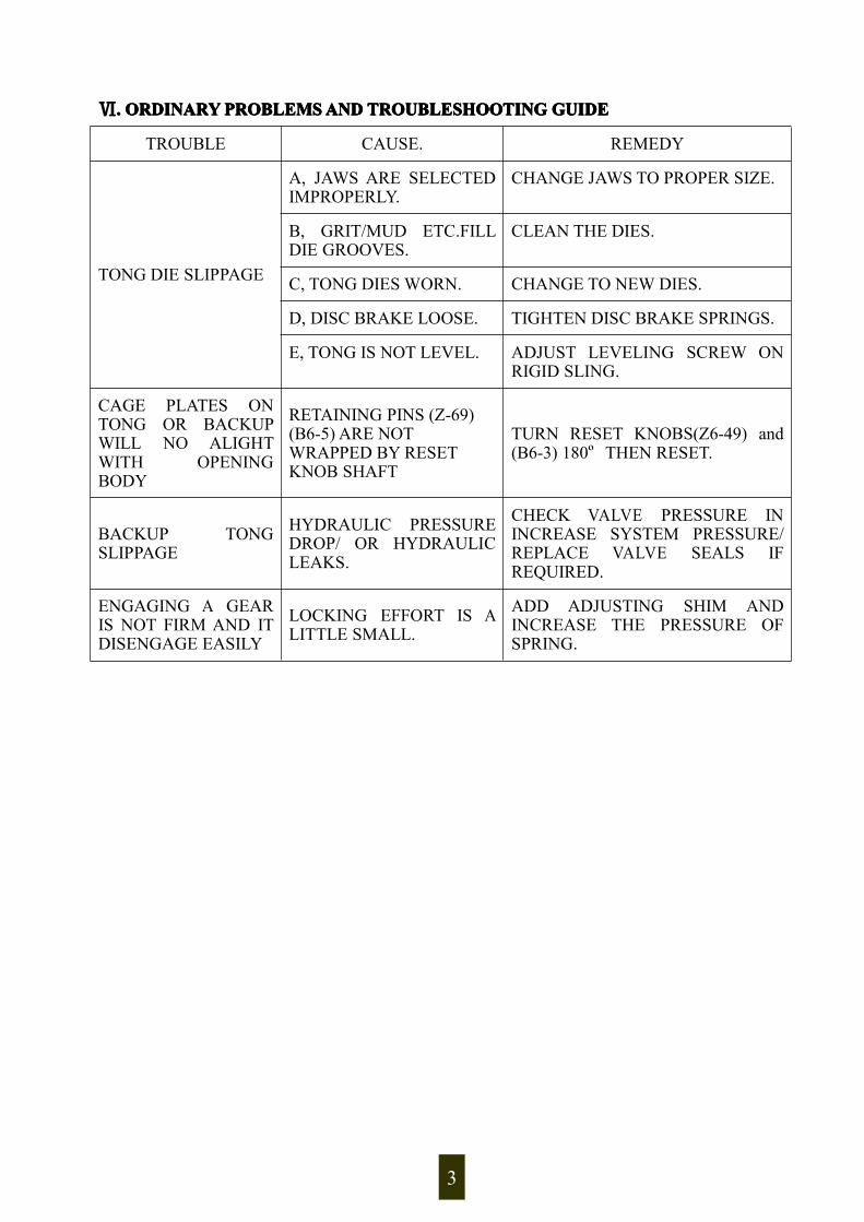
Ⅵ.... ORDINARYORDINARYORDINARYORDINARYPROBLEMSPROBLEMSPROBLEMSPROBLEMSANDANDANDANDTROUBLESHOOTINGTROUBLESHOOTINGTROUBLESHOOTINGTROUBLESHOOTINGGUIDEGUIDEGUIDEGUIDE
TROUBLE CAUSE. REMEDY
TONG DIE SLIPPAGE
A, JAWS ARE SELECTEDIMPROPERLY.
CHANGE JAWS TO PROPER SIZE.
B, GRIT/MUD ETC.FILLDIE GROOVES.
CLEAN THE DIES.
C, TONG DIES WORN. CHANGE TO NEW DIES.
D, DISC BRAKE LOOSE. TIGHTEN DISC BRAKE SPRINGS.
E, TONG IS NOT LEVEL. ADJUST LEVELING SCREW ONRIGID SLING.
CAGE PLATES ONTONG OR BACKUPWILL NO ALIGHTWITH OPENINGBODY
RETAINING PINS (Z-69)(B6-5) ARE NOTWRAPPED BY RESETKNOB SHAFT
TURN RESET KNOBS(Z6-49) and(B6-3) 180º THEN RESET.
BACKUP TONGSLIPPAGE
HYDRAULIC PRESSUREDROP/ OR HYDRAULICLEAKS.
CHECK VALVE PRESSURE ININCREASE SYSTEM PRESSURE/REPLACE VALVE SEALS IFREQUIRED.
ENGAGING A GEARIS NOT FIRM AND ITDISENGAGE EASILY
LOCKING EFFORT IS ALITTLE SMALL.
ADD ADJUSTING SHIM ANDINCREASE THE PRESSURE OFSPRING.
3

Ⅶ. TABLETABLETABLETABLE OFOFOFOF JAWJAWJAWJAWANDANDANDAND DIESDIESDIESDIES
TheTheTheThe tabletabletabletable ofofofof jawjawjawjaw specificationspecificationspecificationspecification
Tubingsize
Tong-jaw size Backup-jaw sizePurchasingnumber Mark Purchasing
number Mark Remark
2-3/8" Z6-79(1) 60-56B6-31(1) 63-60 grip main bodyB6-31(2) 73-70 grip collarB6-31(3) 78-75 grip (EU)(EU)(EU)(EU) collar
2-7/8" Z6-79(2) 73-69B6-31(4) 93-89 grip collarB6-31(2) 73-70 grip main body
3-1/2" Z6-79(3) 89-85B6-31(5) 114.5-107 grip collarB6-31(4) 93-89 grip main body
4" Z6-79(4) 105 B6-31(5) 114.5-107 grip small drill pipe
4-1/2" Z6-79(5) 114-110B6-31(5) 114.5-107 grip main bodyB6-31(6) 141.5-132.5 grip collar
Remark: The customer could select to purchase above jaws according to the requirement.
DiesDiesDiesDies specificationspecificationspecificationspecification
Tubing sizeDies for tong and backup
Purchasing number Mark2-3/8" — 2-7/8" Z6-73(1) 60-783-1/2" — 4-1/2" Z6-73(2) 89-142
Ⅷ.... TORQUETORQUETORQUETORQUE CHARTCHARTCHARTCHARTPSIPSIPSIPSI VSVSVSVS FT.LBS.FT.LBS.FT.LBS.FT.LBS. (4-1/2(4-1/2(4-1/2(4-1/2 TONG)TONG)TONG)TONG)
PSI LOW HIGH100 312 78200 625 156300 936 234400 1249 313500 1562 391600 1874 469700 2186 547800 2499 625900 2810 7031000 3123 7811100 3435 8591200 3748 9381300 4060 10161400 4372 10941500 4685 11721600 4997 1250
4

Ⅸ.... TABLETABLETABLETABLE OFOFOFOFPARTSPARTSPARTSPARTSANDANDANDAND DRAWINGSDRAWINGSDRAWINGSDRAWINGS
Fig. 1 Shell
ItemPurchasingnumber
Part number Part name QTY
1 Z6-4 XYQ6B.Z-2 Shell 12 Z6-57 XYQ6B.Z.3 Fore handle assembly(LH) 13 Z6-3 GB5782-86 Hex bolt M10×20-8.8 64 Z6-62 XYQ6B.Z-31 Retainer plate 25 Z6-130 XYQ3B.Z-69 Pressure and torque relationship table 16 Z6-126 GB65-85 Slotted cylinder head screw M6×10-4.8 127 Z6-67 XYQ6B.Z.4 Fore handle assembly(RH) 18 Z6-1 GB70-85 Hexagon socket head cap screw M10×20-8.8 49 Z6-61 XYQ3B.Z-34 Back handle 210 Z6-129 XYQ6B.Z-68 Name plate 111 Z6-28 XYQ3B.Z-6 Brake spring 112 Z6-56 GB68-85 Slotted countersunk screw M5×15-4.8 213 Z6-27 XYQ6B.Z-15 Tail guy pin 114 Z6-26 GB91-86 Cotter 4×30 115 Z6-32 XYQ6B.Z-18 Back guide rod seat 116 Z6-30 GB70-85 Hexagon socket head cap screw M12×30-8.8 417 Z6-31 GB93-87 Spring washer 12 418 Z6-55 XYQ6B.Z-29 Parallel key 219 Z6-29 XYQ6B.Z-17 Slide 120 Z6-23 XYQ6B.Z-13 Bottom cover 121 Z6-25 GB70-85 Hexagon socket head cap screw M8×20-8.8 6
5

Fig. 2 Brake mechanism and reset mechanism
ItemPurchasingnumber
Part number Part name QTY
1 Z6-50 GB119-86 Cylinder pin 5×18 12 Z6-49 XYQ3B.Z.1-7 Reset knob 13 Z6-44 XYQ6B.Z-23 Brake disc 14 Z6-46 XYQ6B.Z-24 Friction disc 25 Z6-45 GB68-85 Slotted countersunk screw M5×8-4.8 136 Z6-25 GB70-85 Hexagon socket head cap screw M8×20-8.8 87 Z6-48 XYQ6B.Z-26 Brake steel plate 18 Z6-47 XYQ6B.Z-25 Connecting plate 19 Z6-66 GB70-85 Hexagon socket head cap screw M10×25-8.8 1510 Z6-43 XYQ6B.Z-22 Tong cover 111 Z6-54 GB32.2-88 Hex bolt M10×35-8.8 1212 Z6-28 XYQ3B.Z-6 Brake spring 1213 Z6-53 GB65-85 Slotted cylinder head screw M5×20-5.8 214 Z6-52 XYQ3B.B-20 Spring 215 Z6-117 GB308-89 Steel ball 5 216 Z6-128 XYQ3B.Z.1-20 Locating seat 117 Z6-21 GB68-85 Slotted countersunk screw M5×10-4.8 1318 Z6-51 XYQ6B.Z-27 Reset knob shaft 1
6

Fig. 3 Idle shaft
Item Purchasing number Part number Part name QTY1 Z6-39 GB1152-89 Oil cup M8×1 22 Z6-38 XYQ6B.Z-67 Locating plate 23 Z6-97 XYQ6B.Z-48 Idle gear shaft 24 Z6-98 XYQ6B.Z-49 Sleeve 25 Z6-100 XYQ6B.Z-50 Waterproof guard 26 Z6-99 GB1235-76 O ring 36×3.5 27 Z6-102 GB893.1-86 Circlip 72 48 Z6-105 XYQ6B.Z-53 Idle gear 29 Z6-103 GB283-87 Short roller bearing 42306 410 Z6-101 XYQ6B.Z-51 Space ring 211 Z6-104 XYQ6B.Z-52 Washer plate 2
7

Fig. 4 Hanging rod assembly
ItemPurchasingnumber
Part number Part name QTY
1 Z6-42 XYQ6X.1-29 Hanging rod 12 Z6-58 GB70-85 Hexagon socket head cap screw M10×35-8.8 43 Z6-25 GB70-85 Hexagon socket head cap screw M8×20-8.8 84 Z6-59 XYQ6X.1-28 Hanging rod seat 25 Z6-40 XYQ3B.Z-36 Hanging pin shaft 26 Z6-41 GB91-86 Cotter 4×25 2
8

Fig.5 Power input shaft
Item Purchasing number Part number Part name QTY1 Z6-114 XYQ6B.Z-57 Motor liner ring 12 Z6-115 GB276-94 Deep groove ball bearing 310 13 Z6-111 XYQ6B.Z-55 Power input shaft 14 Z6-36 XYQ6B.Z-19 Centralizing washer 25 Z6-17 GB309-84 Roller needle Ф4×25.8 556 Z6-16 XYQ6B.Z-8 Shifting gear 17 Z6-19 XYQ6B.Z-10 Spline gear 18 Z6-18 XYQ6B.Z-9 Inner gear sleeve 19 Z6-20 XYQ6B.Z.1 Clutch gear assembly 110 Z6-24 XYQ6B.Z-14 Bearing disc 111 Z6-22 GB276-94 Deep groove ball bearing 6305 1
9

Fig.6 Shifting mechanism assembly
Item Purchasing number Part number Part name QTY1 Z6-93 XYQ6B.Z-47 Small shaft 22 Z6-91 XYQ6B.Z-44 Roller sleeve 23 Z6-92 GB848-85 Small washer 8-140HV 24 Z6-84 XYQ6B.Z-45 Fork 15 Z6-94 GB93-87 Spring washer 8 26 Z6-95 GB6172-86 Hex thin nut M8-05 27 Z6-90 XYQ6B.Z-46 Fork shaft 18 Z6-96 XYQ3B.Z.5-10 Handle 19 Z6-83 XYQ3B.Z.6-1 Shaft sleeve 210 Z6-86 XYQ3B.Z.6-4 Roller shaft 111 Z6-87 GB91-86 Cotter 2×10 112 Z6-85 XYQ3B.Z.6-3 Roller 113 Z6-88 XYQ3B.Z.6-5 Roller seat 114 Z6-89 XYQ3B.Z.6-6 Parallel key 1
10

Fig. 7 Centralizing mechanism
ItemPurchasingnumber
Part number Part name QTY
1 Z6-7 XYQ6B.Z-4 Centralizing roller shaft 262 Z6-5 XYQ3B.Z-1 Centralizing roller 263 Z6-46 XYQ6B.Z-24 Friction disc 14 Z6-45 GB68-85 Slotted countersunk screw M5×10-4.8 265 Z6-6 XYQ6B.Z-3 Bottom bearing disc 16 Z6-9 GB891-86 Retainer ring B18 137 Z6-8 GB70-85 Hexagon socket head cap screw M5×15-8.8 13
11

Fig. 8 Tong head assembly
Item Purchasing number Part number Part name QTY1 Z6-70 XYQ6B.Z-34 Open gear cover 12 Z6-81 XYQ6B.Z-32 Stop screw M12×25 23 Z6-71 XYQ6B.Z-35 Jaw set bracket 14 Z6-80 XYQ6B.Z-43 Ramp 45 Z6-72 XYQ6B.Z-36 Open gear 16 Z6-1 GB70-85 Hexagon socket head cap screw M10×20-8.8 4
12

7 Z6-82 GB70-85 Hexagon socket head cap screw M10×16-8.8 48 Z6-69 XYQ6B.Z-33 Retainer pin 14×40 19 Z6-68 GB70-76 Hexagon socket head cap screw M8×30 1310 Z6-73 XYQ6B.Z-37 Die piece 411 Z6-77 GB71-85 Slotted cone end fastening screw M10×10-14H 412 Z6-76 XYQ6B.Z-40 Roller shaft 213 Z6-74 XYQ6B.Z-38 Die piece retainer pin 814 Z6-75 XYQ3B.Z.1-18 Spring 815 Z6-78 XYQ6B.Z-41 Roller 216 Z6-79 XYQ6B.Z-42 Jaw set 2
Fig. 9 Duplex gear shaft
Item Purchasing number Part number Part name QTY1 Z6-39 GB1152-89 Oil cup M8×1 12 Z6-37 GB70-85 Hexagon socket head cap screw M6×15-8.8 13 Z6-38 XYQ6B.Z-20 Locating plate 14 Z6-14 XYQ6B.Z-6 Duplex gear shaft 15 Z6-13 XYQ6B.Z-12 Support ring 26 Z6-12 GB893.1-86 Circlip 62 27 Z6-11 GB271-87 Bearing 42206 28 Z6-15 XYQ6B.Z-7 Space ring 19 Z6-10 XYQ6B.Z-5 Duplex gear 1
13

Fig. 10 Hydraulic motor
ItemPurchasingnumber
Part number Part name QTY
1 Z6-113 GB70-85 Hexagon socket head cap screw M12×40-8.8 42 Z6-31 GB93-87 Spring washer 12 43 Z6-112 XYQ6B.Z-56 Motor connecting seat 14 Z6-114 XYQ6B.Z-57 Motor sleeve 15 Z6-35 Hydraulic motor BM-D500 16 Z6-131 XYQ3C.Z.5 Hand control valve 1
14

Fig. 11 Safety door assembly
ItemPurchasingnumber
Part number Part name QTY
1 Z6-119 XYQ6B.Z-62 Rotation shaft(1) 12 Z6-122 GB71-85 Slotted cone end fastening screw M6×16 13 Z6-120 XYQ6B.Z.5 Safety door 14 Z6-132 GB93-87 Spring washer 16 15 Z6-124 XYQ6B.Z-66(2) Rotation shaft 16 Z6-124 XYQ6B.Z-65 Pull spring 17 Z6-44 XYQ6B.Z-23 Brake disc 18 Z6-43 XYQ6B.Z-22 Tong cover 19 Z6-4 XYQ6B.Z-2 Shell 1
15
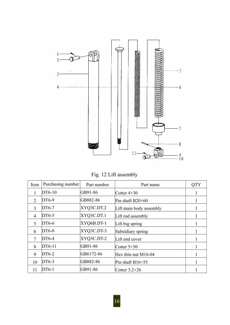
Fig. 12 Lift assembly
Item Purchasing number Part number Part name QTY
1 DT6-10 GB91-86 Cotter 4×30 1
2 DT6-9 GB882-86 Pin shaft B20×60 1
3 DT6-7 XYQ3C.DT.2 Lift main body assembly 1
4 DT6-5 XYQ3C.DT.1 Lift rod assembly 1
5 DT6-6 XYQ6B.DT-1 Lift big spring 1
6 DT6-8 XYQ3C.DT-3 Subsidiary spring 1
7 DT6-4 XYQ3C.DT-2 Lift end cover 1
8 DT6-11 GB91-86 Cotter 5×50 1
9 DT6-2 GB6172-86 Hex thin nut M16-04 1
10 DT6-3 GB882-86 Pin shaft B16×55 1
11 DT6-1 GB91-86 Cotter 3.2×26 1
16

Fig.Fig.Fig.Fig. 11113333 BackupBackupBackupBackup tongtongtongtong headheadheadhead
17

Item Purchasingnumber Part number Part name QTY
1 3C1-70 GB70-85 Hexagon socket head cap screw M8×25-8.8 42 B6-64 XYQ1.8Z-24 Tong head handle 23 B6-1 XYQ6B.B-1 Backup tong head cover 14 B6-6 XYQ6B.B-5 Backup tong jaw set bracket 15 B6-25 XYQ6B.Z-44 Set screw 26 B6-24 XYQ6B.B-13 Ramp 47 B6-22 GB70-85 Hexagon socket head cap screw M12×25-8.8 48 B6-23 GB93-87 Spring washer 12 49 B6-21 XYQ6B.B-12 Backup fore support seat 210 B6-7 XYQ6B.B-6 Backup tong head main body 111 B6-20 GB70-85 Hexagon socket head cap screw M12×20-8.8 412 B6-67 GB70-85 Hexagon socket head cap screw M12×15-8.8 413 B6-63 GB70-85 Hexagon socket head cap screw M10×30-8.8 1214 B6-2 GB119-86 Cylinder pin 5×18 115 B6-3 XYQ3B.B-2 Backup reset knob 116 B6-16 XYQ3B.B-20 Spring 217 B6-17 GB308-89 Steel ball 5 218 B6-65 XYQ6B.B-25 Centralizing shaft 119 B6-66 XYQ6B.B-26 Centralizing roller 120 B6-4 XYQ6B.B-3 Backup reset knob shaft 121 B6-5 XYQ6B.B-4 Retainer pin 122 B6-32 XYQ6B.Z-37 Die 223 B6-28 GB71-85 Slotted cone end fastening screw M6×10-14H 424 B6-30 XYQ6B.Z-40 Roller shaft 225 B6-27 XYQ6B.Z-38 Die retainer pin 826 B6-26 XYQ3B.Z.1-18 Spring 827 B6-29 XYQ6B.Z-41 Roller 2
28 B6-31 XYQ6B.B-14( 1) -(5)
Jaw set 2 pcs for
each kind
18

Fig.Fig.Fig.Fig. 11114444 BackupBackupBackupBackup tongtongtongtong tailtailtailtail
19

ItemPurchasingnumber
Part number Part name QTY
1 B6-10 GB70-85 Hexagon socket head cap screw M6×15-8.8 32 B6-13 GB70-85 Hexagon socket head cap screw M6×20-8.8 53 B6-12 XYQ6B.B-9 Gear cover 14 B6-9 XYQ6B.Z-20 Setting plate 15 B6-8 XYQ6B.B-7 Rotation shaft 16 B6-11 XYQ6B.B-8 Duplex gear 17 B6-68 GB1096-76 Parallel key 16×10×56 28 B6-15 XYQ6B.B-10 Tong tail oil cylinder 19 B6-34 GB898-88 Double head bolt M16×55-8.8 410 B6-33 GB93-87 Spring washer 16 411 B6-47 GB6170-86 Hex head nut M16-8 412 B6-37 XYQ6B.B-15C Cylinder cover 213 B6-71 GB1235-76 O ring 40×3.1 214 B6-72 GB1235-76 RingA40×1.5 215 B6-73 XYQ6B.B-22A Plunger 216 B6-74 XYQ6B.B-27 Support ring 217 B6-75 GB1235-76 O ring 55×3.1 218 B6-38 XYQ6B.B-16B Oil cylinder cover 219 B6-35 GB70-85 Hexagon socket head cap screw M10×30-8.8 820 B6-13 XYQ3B.B-9 Oil passing bolt 421 B6-14 GB1235-76 O ring 22×2.4 922 B6-18 XYQ3B.B-12 Longer adapter 123 B6-43 JB/ZQ4427-86 Hose adapter 10Ⅱ-600 224 B6-45 XYQ6B.B-18 Joint 225 B6-95 XYQ6B.B-11 Hex head bolt M12×80×30 226 B6-96 GB93-87 Spring washer 12 227 B6-62 XYQ6B.B-24(1) Tong tail seat 128 B6-41 XYQ6B.B-17C Rack plunger 129 B6-97 GB6710-86 Hex nut M12 2
20

Fig. 15 Fore guide rod assemblyItem Purchasing number Part number Part name QTY1 QD6-6 XYQ6B.QD.1 Fore guide rod assembil 22 QD6-8 XYQ6B.QD-2 Spring 23 3C4-5 XYQ3B.HD-5 Pin shaft 24 3C3-6 GB91-86 Cotter 2.5×20 25 QD6-10 XYQ6B.QD-1 Fore guide rod 26 QD6-11 XYQ6B.QD-4 End cover 27 QD6-12 GB71-85 Slotted cone end fastening screwM6×10-14H 2
21

Fig. 16 Back guide rod assembly
Item Purchasing numberPart
numberPart name QTY
1 HD6-7 XYQ6B.HD.1 Back guide rod assembly 1
2 HD6-8 XYQ6B.HD-3 Spring 1
3 HD6-10 GB91-86 Cotter 2.5×20 1
4 HD6-11 XYQ3C.HD-5 Pin shaft 1
5 HD6-12 XYQ6B.HD-1 Back guide rod 1
6 HD6-14 XYQ6B.HD-4 End cover 1
7 HD6-15 GB71-85 Slotted cone end fastening screwM6×10-14H 1
22
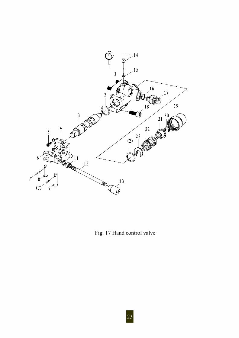
Fig. 17 Hand control valve
23

ItemPurchasingnumber
Part number Part name QTY
1 3C1-110 XYQ3C.Z.5-1 Valve body 12 3C1-113 GB1235-76 O ring 36×3.5 23 3C1-112 XYQ3C.Z.5.1 Combined vale spindle 14 3C1-119 XYQ3C.Z.5-7 Support seat 1
5 3C1-120 GB70-85Hexagon socket head cap screwM6×16 4
6 3C1-122 XYQ3C.Z.5-8 Fork 17 3C1-144 GB91-86 Cotter 3.2×20 28 3C1-121 GB882-86 Pin B10×40 19 3C1-123 GB882-86 Pin B12×45 110 3C1-124 GB93-87 Spring washer 12 111 3C1-125 GB6170-86 Hex nut M12 112 3C1-126 XYQ3C.Z.5-9 Operating handle 113 3C1-127 XYQ3C.Z.5-10 Ball shaped handle 1
143C1-141 XYQ3C.Z.5-12 Plug
13C1-142 Pressure gauge 0~16MPa
15 3C1-143 Copper disc 14×2 116 Z6-63 GB1235-76 O ring 26×2.4 217 Z6-64 XYQ3B.Z-12 Adapter 2
18 3C1-111 GB70-85Hexagon socket head cap screwM12×35 4
19 3C1-114 XYQ3C.Z.5-2 Valve tail seat 120 3C1-118 XYQ3C.Z.5-6 Circlip 121 3C1-117 XYQ3C.Z.5-5 Spring seat (2) 122 3C1-116 XYQ3C.Z.5-4 Spring 123 3C1-115 XYQ3C.Z.5-3 Spring seat(1) 1
24