passport pid ii organic vapor monitor manual 815253
TRANSCRIPT
Passport® PID II Organic Vapor Monitor
User's Manual
WARNING!
THIS MANUAL MUST BE CAREFULLY READ AND FOLLOWED BY ALLPERSONS WHO HAVE OR WILL HAVE THE RESPONSIBILITY FOR USINGOR SERVICING THE PRODUCT. Like any piece of complex equipment, theproduct will perform as designed only if it is used and serviced inaccordance with the manufacturer's instructions. OTHERWISE IT COULDFAIL TO PERFORM AS DESIGNED AND PERSONS WHO RELY ON THISPRODUCT FOR THEIR SAFETY COULD SUSTAIN SEVERE PERSONALINJURY OR DEATH.
The warranties made by Mine Safety Appliances Company with respectto the product are voided if the product is not used and serviced inaccordance with the instructions in this manual. Please protectyourself and others by following them. We encourage our customersto write or call regarding this equipment prior to use, or for anyadditional information relative to use or repairs.
For safety reasons this equipment must be operated by qualified personnelonly.
In the US, contact your nearest stocking location by dialing toll-free,1-800-MSA-2222.To contact MSA International, dial 1-412-967-3000 or 1-800-MSA-7777.
© MINE SAFETY APPLIANCES COMPANY 2000
Manufactured byMSA INSTRUMENT DIVISIONP.O. Box 427, Pittsburgh, Pennsylvania 15230(L) Rev. 6 815253

Contents
Passport PID II, User's Manual i
ContentsSection 1. General Information ....................................................... 1-1
1.1. Certifications .......................................................................... 1-1
Intrinsic Safety.................................................................. 1-1
1.2. Theory and Definitions ........................................................... 1-1
PID Theory ....................................................................... 1-1
Calculating Concentration................................................. 1-1
Zero gas ..................................................................... 1-2
Span gas..................................................................... 1-2
Response Factors............................................................... 1-3
Calculating a Response Factor........................................... 1-3
Calculating Exposures....................................................... 1-4
Threshold Limit Values (TLV).......................................... 1-4
TLV-Time Weighted Average (TWA) ........................... 1-5
TLV-Short Term Exposure Limit (STEL) ..................... 1-5
TLV-Ceiling (TLV-C).................................................. 1-6
Section 2. Safety Information........................................................... 2-1
2.1. Warnings.............................................................................. 2-1
2.2. Cautions ............................................................................... 2-3
Section 3. Using Your Monitor ........................................................ 3-1
3.1. Physical Description ............................................................. 3-1
PID Lamp, Inlet & Outlet Ports ......................................... 3-2
3.2. Instrument Manual ............................................................... 3-3
International Icons ............................................................ 3-3

Contents
ii (L) Revision 6
3.3. Instrument Software ............................................................. 3-4
Display Page ..................................................................... 3-4
Instrument Configuration .................................................. 3-5
Power Saving Mode .......................................................... 3-5
3.4. Preparing for Startup ............................................................ 3-6
Probe Assembly................................................................. 3-6
Connecting the Probe ........................................................ 3-6
Installing the Battery Pack ................................................ 3-7
Self-Test Messages............................................................ 3-8
Set Date and Time............................................................. 3-9
Changing the Date and Time............................................. 3-9
3.5. Instrument Startup.............................................................. 3-11
Fresh Air Setup ............................................................... 3-13
Perform a Fresh Air Setup............................................... 3-13
Bypass Fresh Air Setup ................................................... 3-13
3.6. Checking the Pump Module................................................ 3-14
3.7. Calibration Check............................................................... 3-14
3.8. Exposure Page .................................................................... 3-15
Time-out Feature...................................................... 3-15
Normal Exposure Page.................................................... 3-15
Available Buttons ..................................................... 3-15
Analog Bar Graph Display....................................... 3-16
Alarmed Exposure Page .................................................. 3-16
3.9. Concentration Alarms......................................................... 3-17
Resetting a Concentration Alarm..................................... 3-18
3.10. System Alarms ................................................................... 3-18
Contents
Passport PID II Monitor, User's Manual iii
BATT System Alarm....................................................... 3-20
Resetting a BATT System Alarm .................................... 3-20
BATTERY SHUTDOWN System Alarm......................... 3-20
LAMP System Alarm...................................................... 3-21
Resetting a LAMP System Alarm.................................... 3-21
PUMP System Alarm ...................................................... 3-21
Resetting a PUMP System Alarm .................................... 3-21
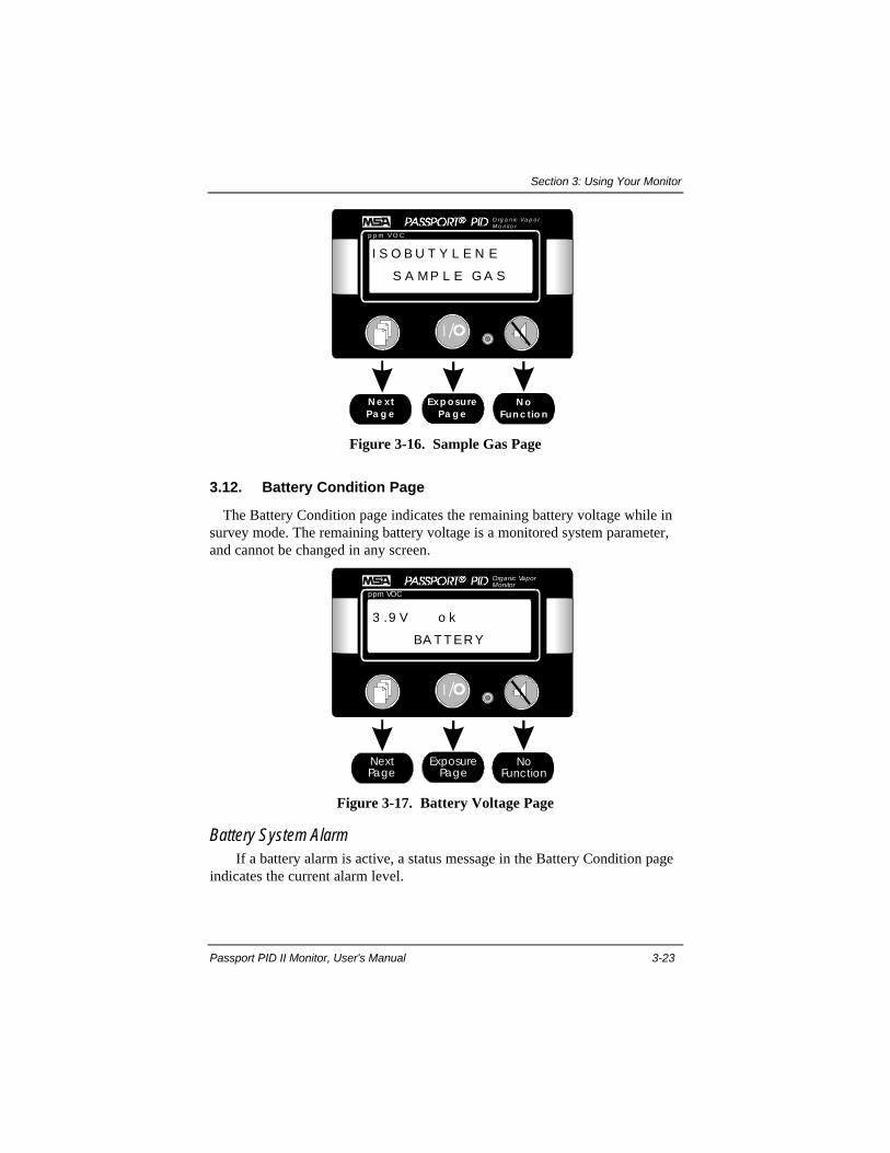
3.11. Sample Gas Page ................................................................ 3-22
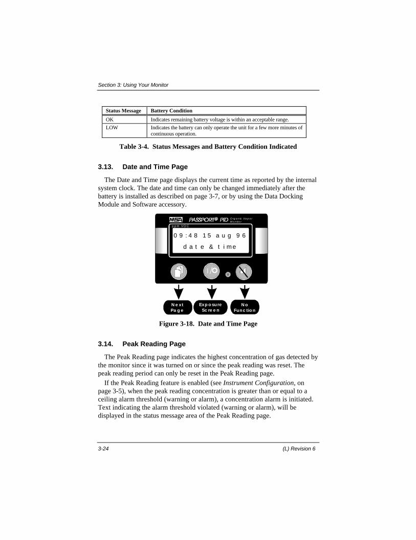
3.12. Battery Condition Page....................................................... 3-23
Battery System Alarm ..................................................... 3-23
3.13. Date and Time Page ........................................................... 3-24
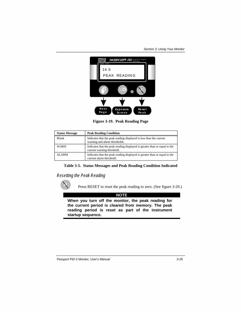
3.14. Peak Reading Page ............................................................. 3-24
Resetting the Peak Reading ............................................. 3-25
3.15. Short Term Exposure Limit (STEL) Page ........................... 3-26
STEL Alarm ................................................................... 3-27
Acknowledging a STEL Alarm ....................................... 3-27
Resetting a STEL Period ................................................. 3-27
3.16. TWA Page.......................................................................... 3-29
TWA Alarm.................................................................... 3-29
Acknowledging a TWA Alarm........................................ 3-30
Resetting a TWA Period.................................................. 3-30
3.17. Open User Setup Page ....................................................... 3-31
Starting Setup Mode........................................................ 3-31
3.18. Instrument Shut Down........................................................ 3-32
Battery Pack Removal ..................................................... 3-33
3.19. Recharging Nickel-Cadmium (Ni-Cd) Battery Packs .......... 3-33
Contents
iv (L) Revision 6
Section 4. Defining the Setup Parameters ....................................... 4-1
4.1. Setup Mode Display Pages.................................................... 4-1
4.2. Select Sample Gas ................................................................ 4-1
Changing the Sample Gas ................................................. 4-1
4.3. Select Label .......................................................................... 4-2
Changing the Storage Label .............................................. 4-3
4.4. Select Warning Level ........................................................... 4-4
Changing the Warning Level ............................................ 4-4
4.5. Select Alarm Level ............................................................... 4-5
Changing the Alarm Level ................................................ 4-5
4.6. Select STEL Level ................................................................ 4-6
Changing the STEL Level ................................................. 4-6
4.7. Select TWA Level ................................................................ 4-7
Changing the TWA Level ................................................. 4-8
Section 5. Calibrating ...................................................................... 5-1
5.1. Calibration ........................................................................... 5-1
Calibration Equipment ...................................................... 5-1
5.2. Calibration Check................................................................. 5-2
5.3. Calibration Procedure ........................................................... 5-2
Initiate Calibration ............................................................ 5-2
Select the Calibration Gas ................................................. 5-5
Applying Zero Gas ............................................................ 5-6
Applying the Span Gas...................................................... 5-7
Section 6. Cleaning & Routine Care................................................ 6-1
6.1. Storage ................................................................................. 6-1
6.2. Shipping............................................................................... 6-1
6.3. Technical Support ................................................................ 6-2
Contents
Passport PID II Monitor, User's Manual v
6.4. Quick Tab Troubleshooting Guide ........................................ 6-3
6.5. Maintenance & Technical Procedures................................... 6-4
Removing and Cleaning the PID Lamp ............................. 6-4
Pump Module Replacement............................................... 6-6
Pump Board Replacement ................................................. 6-7
Pump & Drive Replacement .............................................. 6-7
Pump Motor Replacement ................................................. 6-8
Rebuilding the Pump & Drive ........................................... 6-8
Main Board Replacement .................................................. 6-9
Display Module Replacement .......................................... 6-11
Section 7. Appendices....................................................................... 7-1
Appendix A: Response Factor Table ............................................... 7-1
Appendix B: Additional Response Factors ...................................... 7-3
Appendix C: Specifications............................................................. 7-5
Appendix D: Options and Accessories ............................................ 7-6
Appendix E: Ionization Potentials................................................... 7-9
Contents
vi (L) Revision 6
List of FiguresFigure 1-1. Calibrated Response Curve ................................................. 1-2
Figure 3-1. Passport PID II Organic Vapor Monitor.............................. 3-1
Figure 3-2. Sample Inlet and Data Port ................................................. 3-2
Figure 3-3. Exposure Display Page ....................................................... 3-4
Figure 3-4. Sequence of Display Pages................................................... 3-5
Figure 3-5. Attaching the Sample Line ................................................. 3-6
Figure 3-6. Installing a Water Trap Filter ............................................. 3-7
Figure 3-7. Installing the Battery Pack.................................................. 3-7
Figure 3-8. Operating System Software Version.................................... 3-8
Figure 3-9. Self-Test Display Page........................................................ 3-8
Figure 3-10. Date and Time Display Page............................................. 3-9
Figure 3-11. Date and Time Selection Page ........................................ 3-10
Figure 3-12. Startup Sequence ............................................................ 3-12
Figure 3-13. Exposure Page ................................................................ 3-16
Figure 3-14. Alarmed Exposure Display – Concentration Alarm......... 3-17
Figure 3-15. Alarmed Exposure Display-Lamp System Alarm ............ 3-19
Figure 3-16. Sample Gas Page ............................................................ 3-23
Figure 3-17. Battery Voltage Page ...................................................... 3-23
Figure 3-18. Date and Time Page........................................................ 3-24
Figure 3-19. Peak Reading Page ......................................................... 3-25
Figure 3-20. Resetting the Peak Reading............................................. 3-26
Figure 3-21. STEL Page ..................................................................... 3-27
Figure 3-22. Resetting a STEL Alarm................................................. 3-28
Figure 3-23. TWA Page...................................................................... 3-29
Figure 3-24. Resetting a TWA Alarm ................................................. 3-31

Contents
Passport PID II Monitor, User's Manual vii
Figure 3-25. Open User Setup Page .................................................... 3-32
Figure 3-26. Power Down Page........................................................... 3-32
Figure 3-27. Battery Pack Removal..................................................... 3-33
Figure 3-28. Single Unit MSA Omega Ni-Cd Charger Accessory ....... 3-34
Figure 4-1. Selecting the Sample Gas ................................................... 4-2
Figure 4-2. Selecting a Storage Label.................................................... 4-3
Figure 4-3. Selecting the Warning Level............................................... 4-5
Figure 4-4. Selecting the Alarm Level .................................................. 4-6
Figure 4-5. Selecting the STEL Level ................................................... 4-7
Figure 4-6. Selecting the TWA Level.................................................... 4-8
Figure 5-1. Calibration Equipment ....................................................... 5-1
Figure 5-2. Calibration Screen .............................................................. 5-3
Figure 5-3. Calibration Sequence........................................................... 5-4
Figure 5-4. Calibration Gas Display Page ............................................. 5-5
Figure 5-5. Apply Zero Gas Display Page ............................................. 5-6
Figure 5-6. Apply Span Gas Display Page............................................. 5-7
Figure 5-7. Adjusting the Span Gas Concentration ............................... 5-8
Figure 6-1. Cleaning the PID Lamp..................................................... 6-5
Figure 6-2. Removing Debris from the PID Lamp................................. 6-5
Figure 6-3. Removing the Chassis....................................................... 6-10
Figure 6-4. Location of Mounting Screws & Power Connector............ 6-10
Contents
viii (L) Revision 6
List of TablesTable 3-1. International Icons ............................................................... 3-3
Table 3-2. Status Message & Concentration Alarm Indicated.............. 3-18
Table 3-3. Status Message and System Alarm Indicated...................... 3-19
Table 3-4. Status Messages and Battery Condition Indicated............... 3-24
Table 3-5. Status Messages and Peak Reading Condition Indicated.... 3-25
Table 3-6. Status Messages and STEL Condition Indicated................. 3-27
Table 3-7. Status Messages and TWA Condition Indicated ................. 3-29
Section 1: General Information
Passport PID II Monitor, User's Manual 1-1
Section 1. General Information
1.1. Certifications
Intrinsic SafetyThe Passport PID II Organic Vapor Monitor is listed to the Underwriters
Laboratories Standard for Safety UL 913, as an Intrinsically Safe Apparatusapproved for use in Class I, Division I, Groups A, B, C, D; Class II Division I,Groups E, F, G and Class III, Hazardous Locations when used in accordancewith the Passport PID II Instruction Manual. (Listing number: E112042.)
1.2. Theory and Definitions
To support the safe and effective operation of the Passport PID II OrganicVapor Monitor, MSA believes operators should have a working knowledge ofhow the instrument functions, not just how to make it work. The informationpresented in this section supplements the hands-on operational instructionprovided in the rest of the manual.
PID TheoryIn a photoionization detector (PID), sample gas is pumped through a small
chamber illuminated by an ultraviolet lamp. Substances in the sample gas withionization potentials less than or equal to the energy of the ultraviolet light areionized. An electric field set up within the chamber forces the freed electrons toa collector pin that directs the current to the instrument's amplifier. Thiscurrent is called the detector response. The software interprets and reports thedetector response as a concentration.
Calculating ConcentrationThere is a relationship between the detector current and concentration. This
response can be expressed as a straight line on a graph, where only two pointsare necessary to define that line. These two points are defined by determiningthe detector response to reference gases of known concentration. The referencegases are called zero gas and span gas.
By plotting the detector response to reference gases of known concentration,the software generates a curve where the slope of that curve represents thecalibrated response per unit concentration.

Section 1: General Information
1-2 (L) Revision 6
y = mx + b
where:
y =current (pA)
x = concentration (ppm isobutylene)
m = detector response (pA/ppm)
sample concentration
(ppm isobutylene)
span valuezero value
background
span current
detector
current (pA)
Figure 1-1. Calibrated Response Curve
Zero gasZero gas is a reference gas used during calibration to zero the
instrument. When a zero gas with no hydrocarbon content isintroduced to the monitor, the detector will still respond with a smallsignal. This signal is a result of background ionization. Duringcalibration, zero gas is applied to quantify the background ionizationcurrent.
Zero Gas Recommendations: The preferred zero gas is hydrocarbon-free air. However, for applications where you are only interested inconcentration changes relative to a reference ambient environment,fresh air can be used as the zero gas. When background gas is present,MSA recommends using hydrocarbon-free air to zero the unit. Zeroingthe monitor with hydrocarbon-free air reduces the background count,improves response, and decreases the stabilization time required tospan the instrument.
Span gasSpan gas is a reference gas used during calibration to determine the
slope (response per unit concentration) of the calibrated responsecurve.

Section 1: General Information
Passport PID II Monitor, User's Manual 1-3
Span gas Recommendation: MSA strongly recommends that thespan gas used during calibration be well within the concentrationrange you expect to encounter in the survey area.
Response FactorsWhen a compound is ionized by a photoionization detector, it yields a
current. This response is a characteristic property of the specific compoundinfluenced by its molecular structure. The slope of the response curve (definedin picoamperes per ppm) is different for different chemicals. To properly reportthe concentration for a given sample gas, the Passport PID II Monitor usesresponse factors.
The response factor is defined as the ratio of the detector response forisobutylene to the detector response for the sample gas. Response factors to awide range of substances have been determined experimentally. These responsefactors are programmed into the instrument. Note that the calibrated responsecurve, and all programmed response factors are relative to isobutylene.(Isobutylene has a response factor of one.)
The response factor is a multiplier that compensates for the differencebetween the response of the sample gas and the response of isobutylene.Whenever the monitor detects a signal, it uses the response factor for thatchemical to convert the signal to an isobutylene equivalent response. Duringcalibration, this calculation is performed to define the calibrated responsecurve. When sampling, the isobutylene equivalent response is then multipliedby the response factor for the specific sample gas to calculate the concentration.
If the response factor is known, you can use a monitor calibrated onisobutylene to calculate the actual concentration of a target gas.
For example:An operator is using a monitor that has been calibrated on
isobutylene. The sample gas is set to isobutylene. While using thisinstrument to sample for hydrogen sulfide (H2S), the display reads 100ppm. Since the response factor for hydrogen sulfide is 6.25, then theactual concentration of hydrogen sulfide is:
Actual Hydrogen Sulfide Concentration = 6.25 x 100 ppm =625 ppm.
Calculating a Response FactorTo determine a response factor for a target chemical, perform the following
simple procedure:
1. Calibrate the Passport PID II Monitor using isobutylene as the span gas.
Section 1: General Information
1-4 (L) Revision 6
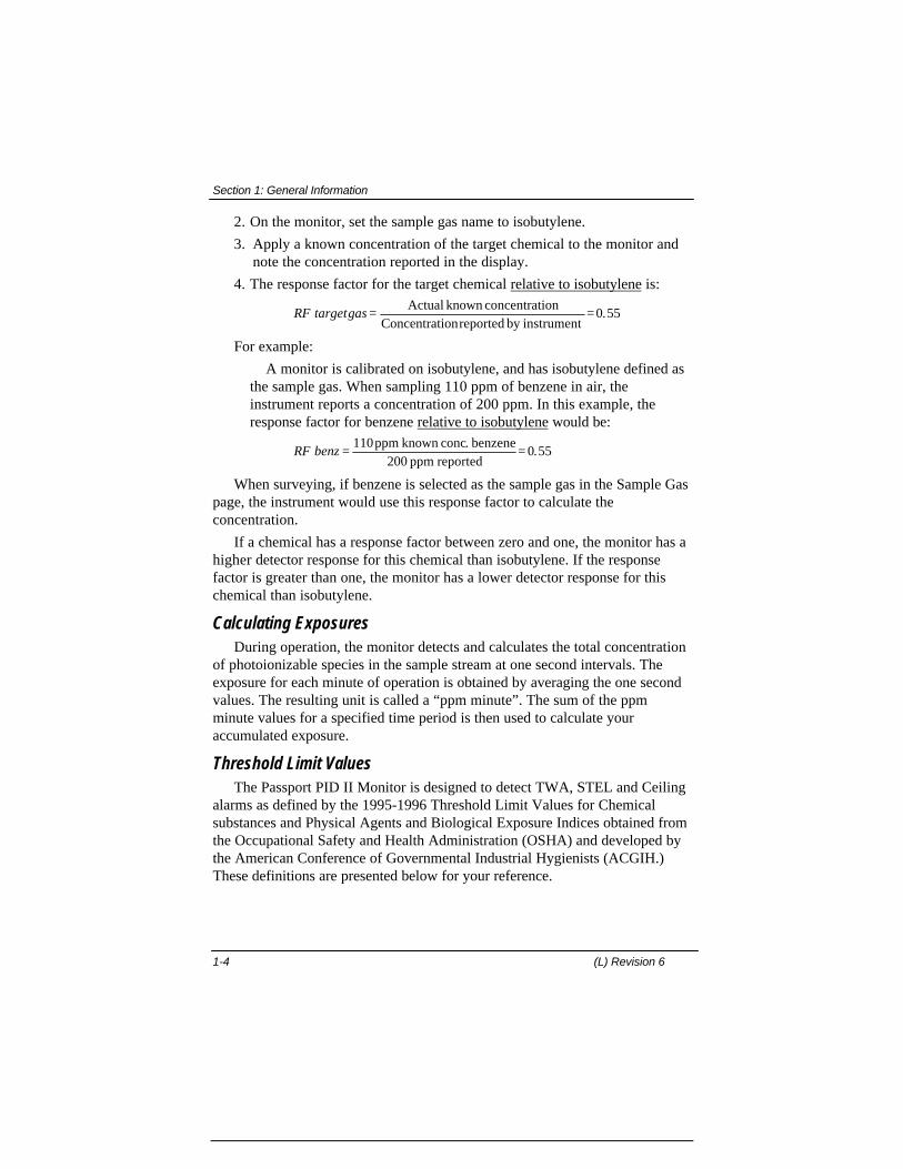
2. On the monitor, set the sample gas name to isobutylene.
3. Apply a known concentration of the target chemical to the monitor andnote the concentration reported in the display.
4. The response factor for the target chemical relative to isobutylene is:
RF targetgas = =Actual known concentrationConcentrationreported by instrument
0 55.
For example:
A monitor is calibrated on isobutylene, and has isobutylene defined asthe sample gas. When sampling 110 ppm of benzene in air, theinstrument reports a concentration of 200 ppm. In this example, theresponse factor for benzene relative to isobutylene would be:
RF benz = =110ppm known conc. benzene200 ppm reported
0 55.
When surveying, if benzene is selected as the sample gas in the Sample Gaspage, the instrument would use this response factor to calculate theconcentration.
If a chemical has a response factor between zero and one, the monitor has ahigher detector response for this chemical than isobutylene. If the responsefactor is greater than one, the monitor has a lower detector response for thischemical than isobutylene.
Calculating ExposuresDuring operation, the monitor detects and calculates the total concentration
of photoionizable species in the sample stream at one second intervals. Theexposure for each minute of operation is obtained by averaging the one secondvalues. The resulting unit is called a “ppm minute”. The sum of the ppmminute values for a specified time period is then used to calculate youraccumulated exposure.
Threshold Limit ValuesThe Passport PID II Monitor is designed to detect TWA, STEL and Ceiling
alarms as defined by the 1995-1996 Threshold Limit Values for Chemicalsubstances and Physical Agents and Biological Exposure Indices obtained fromthe Occupational Safety and Health Administration (OSHA) and developed bythe American Conference of Governmental Industrial Hygienists (ACGIH.)These definitions are presented below for your reference.
Section 1: General Information
Passport PID II Monitor, User's Manual 1-5
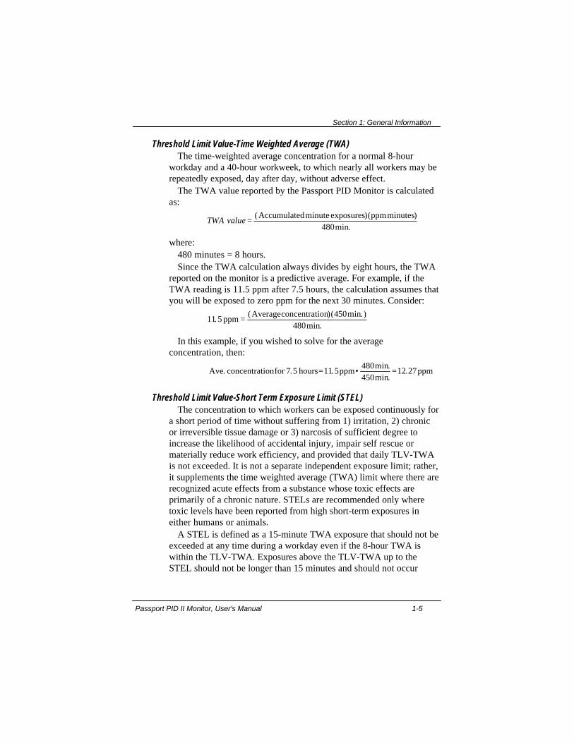
Threshold Limit Value-Time Weighted Average (TWA)The time-weighted average concentration for a normal 8-hour
workday and a 40-hour workweek, to which nearly all workers may berepeatedly exposed, day after day, without adverse effect.
The TWA value reported by the Passport PID Monitor is calculatedas:
TWA value = ( )( )min.
Accumulatedminute exposures ppmminutes480
where:480 minutes = 8 hours.Since the TWA calculation always divides by eight hours, the TWA
reported on the monitor is a predictive average. For example, if theTWA reading is 11.5 ppm after 7.5 hours, the calculation assumes thatyou will be exposed to zero ppm for the next 30 minutes. Consider:
11 5450
480.
( )( min.)min.
ppmAverageconcentration=
In this example, if you wished to solve for the averageconcentration, then:
Ave. concentrationfor 7.5 hours ppm ppm= • =11 5480450
12 27.min.min.
.
Threshold Limit Value-Short Term Exposure Limit (STEL)The concentration to which workers can be exposed continuously for
a short period of time without suffering from 1) irritation, 2) chronicor irreversible tissue damage or 3) narcosis of sufficient degree toincrease the likelihood of accidental injury, impair self rescue ormaterially reduce work efficiency, and provided that daily TLV-TWAis not exceeded. It is not a separate independent exposure limit; rather,it supplements the time weighted average (TWA) limit where there arerecognized acute effects from a substance whose toxic effects areprimarily of a chronic nature. STELs are recommended only wheretoxic levels have been reported from high short-term exposures ineither humans or animals.
A STEL is defined as a 15-minute TWA exposure that should not beexceeded at any time during a workday even if the 8-hour TWA iswithin the TLV-TWA. Exposures above the TLV-TWA up to theSTEL should not be longer than 15 minutes and should not occur

Section 1: General Information
1-6 (L) Revision 6
more than 4 times per day. There should be at least 60 minutesbetween successive exposures in this range. An averaging period otherthan 15 minutes may be recommended when this is warranted byobserved biological effects.
The STEL value reported by the Passport PID II Monitor iscalculated as:
STEL Value = Sum of previousminute exposures(ppm minutes)15 minutes
For the first 15 minutes of sampling, the STEL is predictive then theSTEL value is calculated as above.
Threshold Limit Value-Ceiling (TLV-C)The concentration that should not be exceeded during any part of
the working exposure.

Section 2: Safety Information
Passport PID II Monitor, User's Manual 2-1
Section 2. Safety Information
2.1.Warnings
WARNING!
•• The Passport PID II Monitor contains a photoionizationdetector used to detect the presence and quantity ofphotoionizable species in the sample stream. Theinstrument must be used to detect only photoionizablegases. Toxic chemicals that cannot be ionized by thedetector may be present; however, the Passport PID IIMonitor will not detect these chemicals.
•• The Passport PID II Monitor does not distinguishbetween individual chemicals. The reading displayedrepresents the concentration of all photoionizablespecies present in the sample. The instrument cannotbe used to separate chemicals in a mixture. Care mustbe taken when interpreting the displayedconcentration.
•• Repair or alteration of the Passport PID II Monitorbeyond the scope of these instructions by anyoneother than a person authorized by MSA could causethe monitor to fail to perform as designed. Whenneeded, use only genuine MSA replacement parts.Substitution of components can impair instrumentperformance, alter the intrinsic safety characteristics,or void agency approvals.
•• Use the data port only with MSA approvedaccessories; otherwise, the intrinsic safety of theinstrument may be impaired.
•• Moisture, oxygen, and methane, among othercompounds, will quench the PID signal causing theinstrument to under report concentration readings.This consequence must be understood by personneloperating the instrument.
•• When sampling with accessory sampling lines, use theshortest possible length to minimize the time neededto obtain a valid reading.
Section 2: Safety Information
2-2 (L) Revision 6
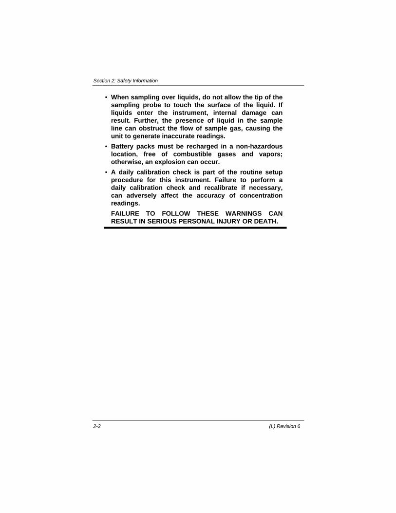
•• When sampling over liquids, do not allow the tip of thesampling probe to touch the surface of the liquid. Ifliquids enter the instrument, internal damage canresult. Further, the presence of liquid in the sampleline can obstruct the flow of sample gas, causing theunit to generate inaccurate readings.
•• Battery packs must be recharged in a non-hazardouslocation, free of combustible gases and vapors;otherwise, an explosion can occur.
•• A daily calibration check is part of the routine setupprocedure for this instrument. Failure to perform adaily calibration check and recalibrate if necessary,can adversely affect the accuracy of concentrationreadings.
FAILURE TO FOLLOW THESE WARNINGS CANRESULT IN SERIOUS PERSONAL INJURY OR DEATH.
Section 2: Safety Information
Passport PID II Monitor, User's Manual 2-3
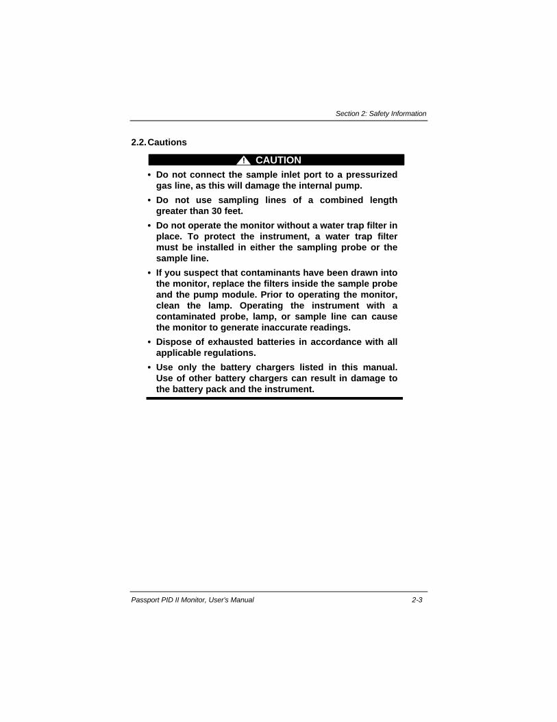
2.2.Cautions
CAUTION!
• Do not connect the sample inlet port to a pressurizedgas line, as this will damage the internal pump.
• Do not use sampling lines of a combined lengthgreater than 30 feet.
• Do not operate the monitor without a water trap filter inplace. To protect the instrument, a water trap filtermust be installed in either the sampling probe or thesample line.
• If you suspect that contaminants have been drawn intothe monitor, replace the filters inside the sample probeand the pump module. Prior to operating the monitor,clean the lamp. Operating the instrument with acontaminated probe, lamp, or sample line can causethe monitor to generate inaccurate readings.
• Dispose of exhausted batteries in accordance with allapplicable regulations.
• Use only the battery chargers listed in this manual.Use of other battery chargers can result in damage tothe battery pack and the instrument.

Section 3: Using Your Monitor
Passport PID II Monitor, User's Manual 3-1
Section 3. Using Your Monitor
3.1. Physical Description
The Passport PID II Organic Vapor Monitor is a portable gas analyzerequipped with a photoionization detector. The user interface features a liquidcrystal display used in conjunction with a three-button keypad. The alarmsystem consists of the alarm lights located on each side of the display and thealarm horn located between the ON/OFF and RESET buttons.
PAGE ON/OFF RESET
Figure 3-1. Passport PID II Organic Vapor Monitor
When monitoring in a noisy environment, the earphone accessory can beused to directly communicate audible alarms to the operator. The earphone jackis located beneath a protective plug on the side of the unit. A battery pack mustbe installed to operate the instrument. Alone, the battery pack can providepower for portable applications. Alternatively, the AC adapter/chargeraccessory can be used with a Type A, or B (heavy-duty) battery pack to powerthe instrument. The AC adapter plugs into the adapter jack located on the sideof the battery pack. A belt-clip located on the bottom of the unit provideshands-free operation of the monitor.
Section 3: Using Your Monitor
3-2 (L) Revision 6
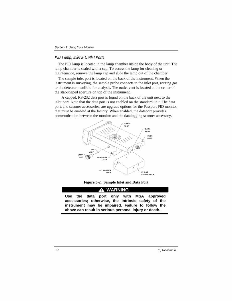
PID Lamp, Inlet & Outlet PortsThe PID lamp is located in the lamp chamber inside the body of the unit. The
lamp chamber is sealed with a cap. To access the lamp for cleaning ormaintenance, remove the lamp cap and slide the lamp out of the chamber.
The sample inlet port is located on the back of the instrument. When theinstrument is surveying, the sample probe connects to the inlet port, routing gasto the detector manifold for analysis. The outlet vent is located at the center ofthe star-shaped aperture on top of the instrument.
A capped, RS-232 data port is found on the back of the unit next to theinlet port. Note that the data port is not enabled on the standard unit. The dataport, and scanner accessories, are upgrade options for the Passport PID monitorthat must be enabled at the factory. When enabled, the dataport providescommunication between the monitor and the datalogging scanner accessory.
LA M PC A P
O UTLET
PO RT
DATAPO RT
IN LETPO RT
EA RPHO N EJAC K
PID
LAM P
N i- C A D
BATTERY PAC K
A C A DA PTERJA C K
Figure 3-2. Sample Inlet and Data Port
WARNING!
Use the data port only with MSA approvedaccessories; otherwise, the intrinsic safety of theinstrument may be impaired. Failure to follow theabove can result in serious personal injury or death.
Section 3: Using Your Monitor
Passport PID II Monitor, User's Manual 3-3
3.2. Instrument Manual
The Passport PID II Monitor performs as designed only when used inaccordance with the manufacturer's instructions presented in this manual.Protect yourself and others—use your manual. When used properly, thePassport PID II Monitor will detect the presence and total concentration ofphotoionizable species. Note that the monitor does not distinguish betweenindividual gases. The reading displayed represents the total concentration of allphotoionizable chemicals present in the sample.
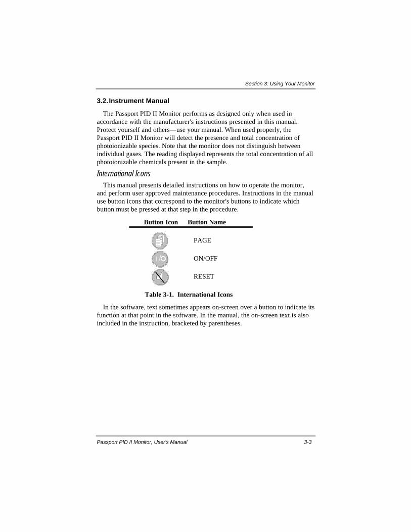
International IconsThis manual presents detailed instructions on how to operate the monitor,
and perform user approved maintenance procedures. Instructions in the manualuse button icons that correspond to the monitor's buttons to indicate whichbutton must be pressed at that step in the procedure.
Button Icon Button Name
PAGE
ON/OFF
RESET
Table 3-1. International Icons
In the software, text sometimes appears on-screen over a button to indicate itsfunction at that point in the software. In the manual, the on-screen text is alsoincluded in the instruction, bracketed by parentheses.

Section 3: Using Your Monitor
3-4 (L) Revision 6
3.3. Instrument Software
Display PageThe monitor uses a software tree to support its monitoring features. The tree
is organized into pages that display on the monitor's screen. Each display pagesupports the unique function provided by the software at that point in thesoftware tree. The monitor's display is formatted so that important informationin the Exposure page is presented clearly and consistently.
PowerDown
ppm VOC
Organic VaporMonitor
NextPage
AknowledgeActive Alarm
200
PPM BATT STA TUS
• System Status Messages for battery, lampor pump alarms appear in the center of thetop line of the screen.
• MonitoredParameterssuch as the currentconcentration,battery voltage andgas name, appearleft justified on thetop line of thescreen.
• A Concentration Bar Graph on thebottom line of the screen indicates thecurrent concentration. Numbers to the rightof the graph indicate the full scale responsefor the current range.
• Status Messagesfor concentrationalarms appear rightjustified on the topline of the screen.
Figure 3-3. Exposure Display Page

Section 3: Using Your Monitor
Passport PID II Monitor, User's Manual 3-5
Instrument ConfigurationFactory Configuration: When the monitor is shippedfrom the factory it is configured to sample at ten secondintervals and supports all the features shown in figure3-4.Changing the Configuration: The configuration of thePassport PID II Monitor can be changed to supportdifferent applications by enabling or disabling itsoptional features. This is accomplished by using the DataLogging Software and Data Docking Module with yourPC to change or disable the following items:• Sampling interval (select a ten second interval or a one
minute interval).• Ceiling Alarm feature (ON or OFF)• Peak Reading feature (ON or OFF)• STEL Alarm feature (ON or OFF)• TWA Alarm feature (ON or OFF)• Data Labeling feature (ON or OFF)
When a feature is disabled, the display page thatsupports that feature is also turned off. No matter howthe instrument is configured, pressing PAGE alwaysopens the next display page enabled on the unit.
Power Saving ModeDuring operation, if the faceplate buttons are inactive
for 60 seconds, the unit goes into power saving mode. Inpower saving mode, the display backlight shuts off toconserve battery life. Monitoring and alarm functions arenot interrupted. Press any key to reactivate the displaybacklight.
V I E W S A MP L EGA S
E XP OS U R E P A GE
2 0
V I E WBA T T E R Y
V I E W D A T E& T I ME
V I E W P E A KD I S P L A Y
V I E W T WAD I S P L A Y
O P E N U S E RS E T U P
V I E W S T E LD I S P L A Y
Figure 3-4. Sequenceof Display Pages
Section 3: Using Your Monitor
3-6 (L) Revision 6
3.4.Preparing for Startup
Prior to operation, the sampling probe must be assembled and attached to themonitor's inlet port, and the battery pack must be installed.
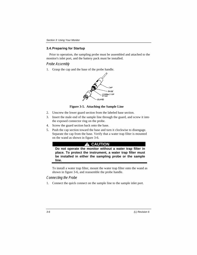
Probe Assembly1. Grasp the cap and the base of the probe handle.
Figure 3-5. Attaching the Sample Line
2. Unscrew the lower guard section from the labeled base section.3. Insert the male end of the sample line through the guard, and screw it into
the exposed connector ring on the probe.4. Screw the guard section back onto the base.5. Push the cap section toward the base and turn it clockwise to disengage.
Separate the cap from the base. Verify that a water trap filter is mountedon the wand as shown in figure 3-6.
CAUTION!Do not operate the monitor without a water trap filter inplace. To protect the instrument, a water trap filter mustbe installed in either the sampling probe or the sampleline.
To install a water trap filter, mount the water trap filter onto the wand asshown in figure 3-6, and reassemble the probe handle.
Connecting the Probe1. Connect the quick connect on the sample line to the sample inlet port.

Section 3: Using Your Monitor
Passport PID II Monitor, User's Manual 3-7
Figure 3-6. Installing a Water Trap Filter
Installing the Battery Pack1. Align the battery pack with the battery contact on the back of the monitor
body as shown. Press the battery into the socket. Using a dime or ascrewdriver, turn the “quarter-turn fastener” on the bottom of theinstrument clockwise to secure the battery pack to the unit.
Q UA RTER TURNFA STEN ER
BATTERYPA C K
BATTERY C O NTA C T
M O N ITO R BO D Y
Figure 3-7. Installing the Battery Pack
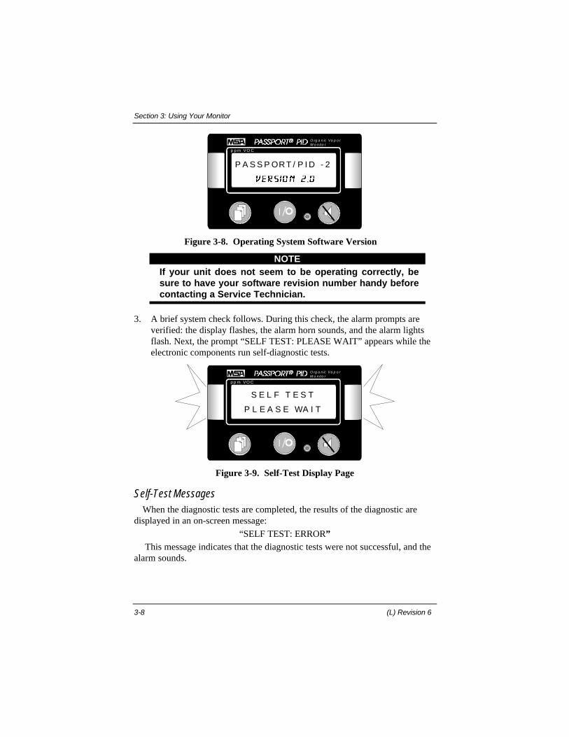
2. When the battery is engaged, the display lights, and the revision level ofthe operating system software is reported on-screen. Note that the faceplatebuttons are disabled while the unit reports its software version and runsself-diagnostic tests.
Section 3: Using Your Monitor
3-8 (L) Revision 6
p p m VO C
O rg a n ic Va p o rM o n ito r
P A S S P OR T / P I D - 2
Figure 3-8. Operating System Software Version
NOTEIf your unit does not seem to be operating correctly, besure to have your software revision number handy beforecontacting a Service Technician.
3. A brief system check follows. During this check, the alarm prompts areverified: the display flashes, the alarm horn sounds, and the alarm lightsflash. Next, the prompt “SELF TEST: PLEASE WAIT” appears while theelectronic components run self-diagnostic tests.
p p m VO C
O rg a n ic Va p o rM o n ito r
S E L F T E S T
P L E A S E WA I T
Figure 3-9. Self-Test Display Page
Self-Test MessagesWhen the diagnostic tests are completed, the results of the diagnostic are
displayed in an on-screen message:
“SELF TEST: ERROR” This message indicates that the diagnostic tests were not successful, and the
alarm sounds.
Section 3: Using Your Monitor
Passport PID II Monitor, User's Manual 3-9
NOTEIf the prompt “SELF TEST: ERROR” appears, turn off themonitor and consult the Troubleshooting Guide found inSection 6, Cleaning & Routine Care. Do not use theinstrument for protection.
“SELF TEST: OK”This message indicates that the diagnostic tests were successful.
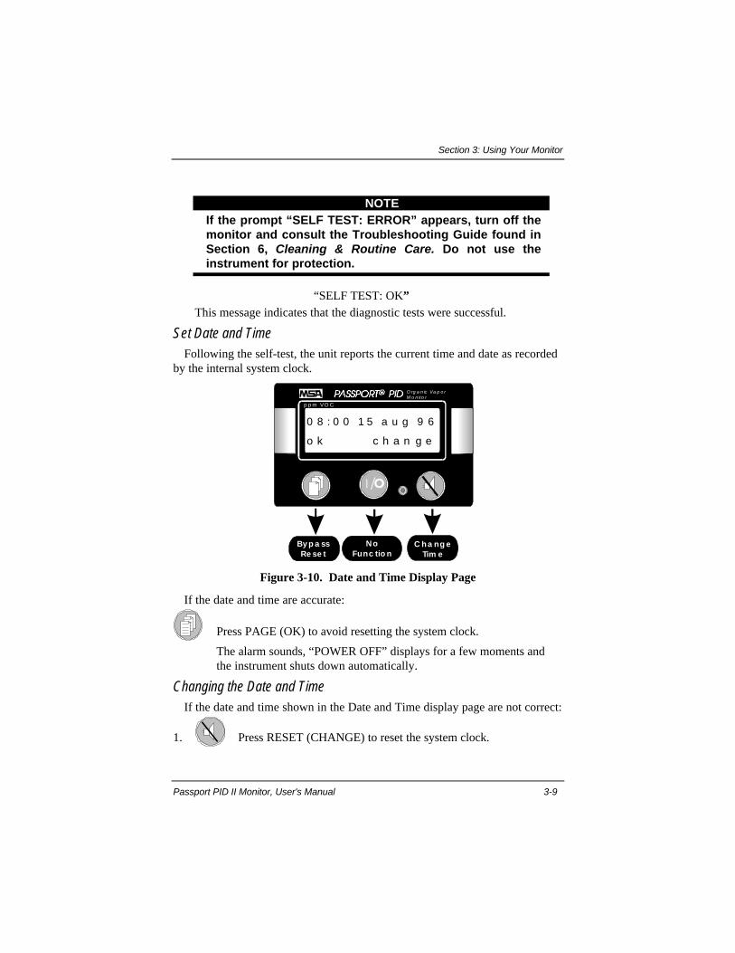
Set Date and TimeFollowing the self-test, the unit reports the current time and date as recorded
by the internal system clock.
NoFunc tio n
p p m VO C
O rg a n ic Va p o rM o n ito r
By p a ssRe se t
C ha ng eTim e
0 8 : 0 0 1 5 a u g 9 6
o k c h a n g e
Figure 3-10. Date and Time Display Page
If the date and time are accurate:
Press PAGE (OK) to avoid resetting the system clock.
The alarm sounds, “POWER OFF” displays for a few moments andthe instrument shuts down automatically.
Changing the Date and TimeIf the date and time shown in the Date and Time display page are not correct:
1. Press RESET (CHANGE) to reset the system clock.
Section 3: Using Your Monitor
3-10 (L) Revision 6
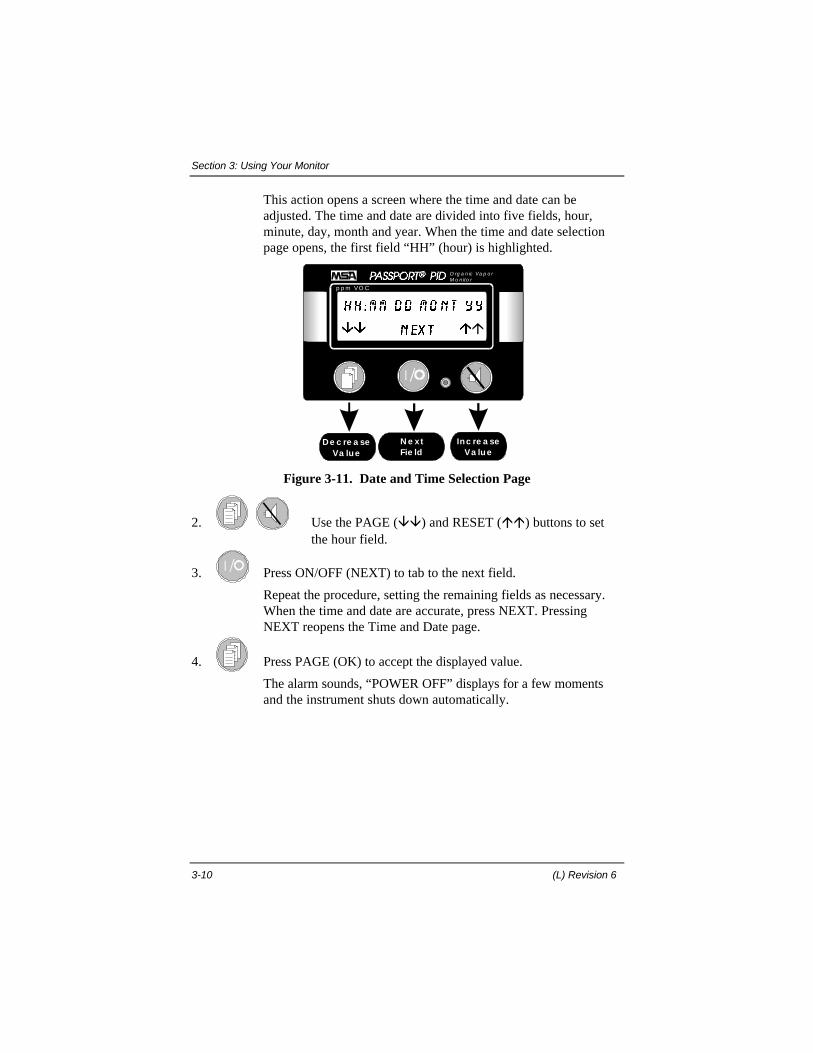
This action opens a screen where the time and date can beadjusted. The time and date are divided into five fields, hour,minute, day, month and year. When the time and date selectionpage opens, the first field “HH” (hour) is highlighted.
N e xtFie ld
p p m VO C
O rg a n ic Va p o rM o n ito r
De c re a seVa lue
Inc re a seVa lue
Figure 3-11. Date and Time Selection Page
2. Use the PAGE (ââ) and RESET (áá) buttons to setthe hour field.
3. Press ON/OFF (NEXT) to tab to the next field.
Repeat the procedure, setting the remaining fields as necessary.When the time and date are accurate, press NEXT. PressingNEXT reopens the Time and Date page.
4. Press PAGE (OK) to accept the displayed value.
The alarm sounds, “POWER OFF” displays for a few momentsand the instrument shuts down automatically.
Section 3: Using Your Monitor
Passport PID II Monitor, User's Manual 3-11
3.5. Instrument Startup
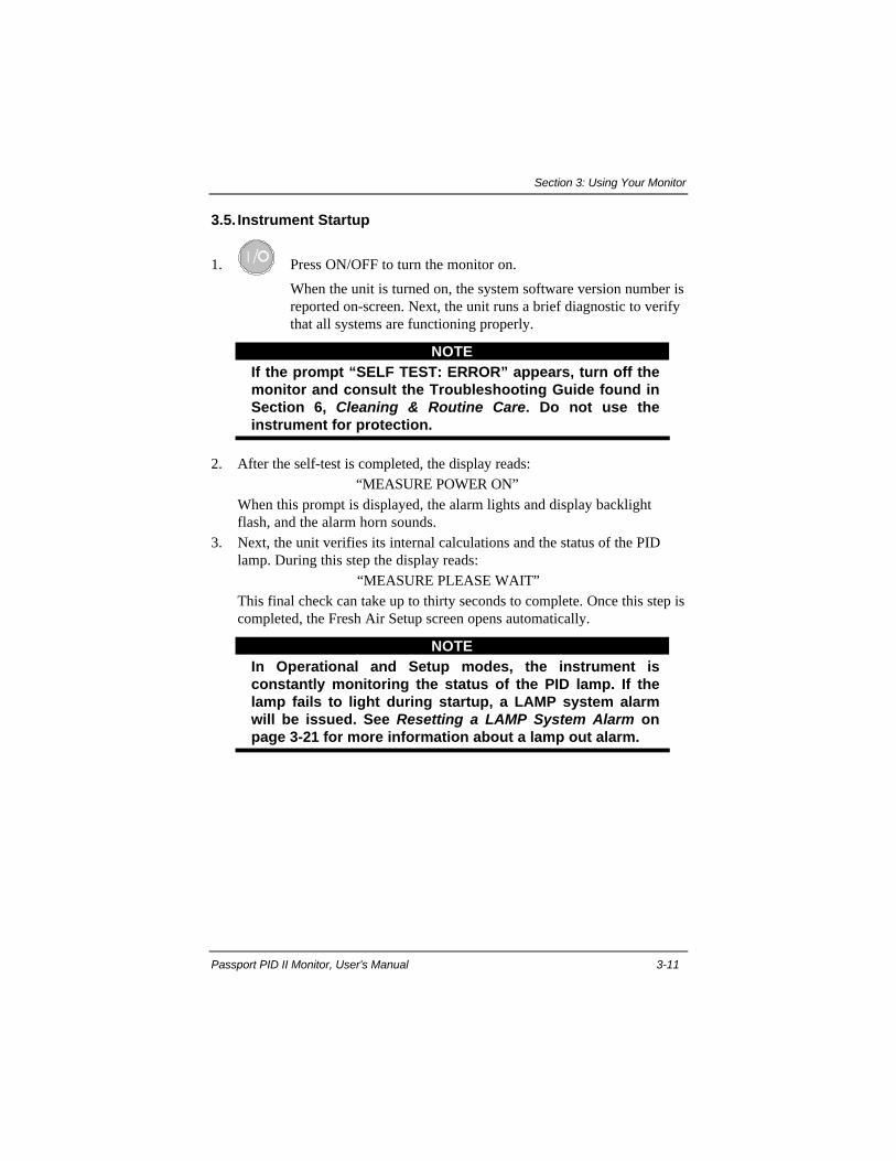
1. Press ON/OFF to turn the monitor on.
When the unit is turned on, the system software version number isreported on-screen. Next, the unit runs a brief diagnostic to verifythat all systems are functioning properly.
NOTEIf the prompt “SELF TEST: ERROR” appears, turn off themonitor and consult the Troubleshooting Guide found inSection 6, Cleaning & Routine Care. Do not use theinstrument for protection.
2. After the self-test is completed, the display reads:“MEASURE POWER ON”
When this prompt is displayed, the alarm lights and display backlightflash, and the alarm horn sounds.
3. Next, the unit verifies its internal calculations and the status of the PIDlamp. During this step the display reads:
“MEASURE PLEASE WAIT”This final check can take up to thirty seconds to complete. Once this step iscompleted, the Fresh Air Setup screen opens automatically.
NOTEIn Operational and Setup modes, the instrument isconstantly monitoring the status of the PID lamp. If thelamp fails to light during startup, a LAMP system alarmwill be issued. See Resetting a LAMP System Alarm onpage 3-21 for more information about a lamp out alarm.
Section 3: Using Your Monitor
3-12 (L) Revision 6
p p m V O C
O rg a n ic Va p o rM o n it o r
F R E S H A I R S E T U P ?
N O Y E S
N o re sp o nsefo r 5 se c o nd s
p p m V O C
O r g a n ic V a p o rM o n it o r
F R E S H A I R S E T U P
P L E A S E WA I T
p p m V O C
O rg a n ic Va p o rM o n it o r
M E A S U R E
P L E A S E WA I T
p p m V O C
O rg a n ic Va p o rM o n it o r
P O WE R O N
M E A S U R E
p p m V O C
O rg a n ic Va p o rM o n ito r
P A S S P O R T / P I D - 2V E R S I O N 2 . 0
Exp osurePa g e
N o Func tion
Byp a ss Fre shA ir Se tup
Exp o surePa g e
Exp osurePa g e
Fre sh Air Se tupC om p le te d
Pow e rO n
Butto ns Disa b le d in this Pa g e
Butto ns Disa b le d in th is Pa g e Butto ns Disa b le d in th is Pa g e
Butto ns Disa b le d in this Pa g e
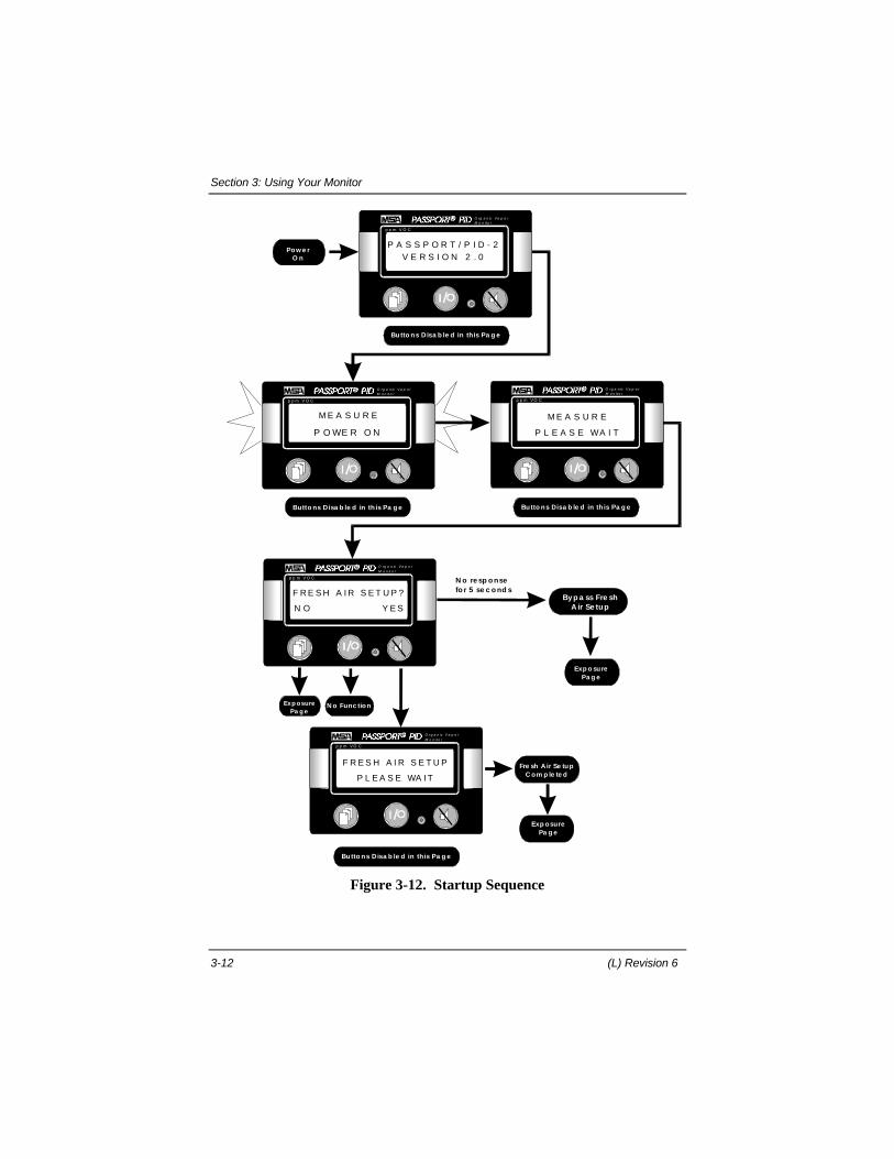
Figure 3-12. Startup Sequence
Section 3: Using Your Monitor
Passport PID II Monitor, User's Manual 3-13
Fresh Air SetupThe Fresh Air Setup option allows you to zero the instrument on ambient air.
NOTEThe Fresh Air Setup procedure is not a substitute for acomplete calibration.
From the Fresh Air Setup display page, you can initiate or bypass this option.If the unit does not receive a response to the “FRESH AIR SETUP?” querywithin 5 seconds, fresh air setup is bypassed and the Exposure page opensautomatically.
Perform a Fresh Air Setup
Press RESET (YES) in the Fresh Air Setup page to initiate a fresh airsetup. The display responds:
“FRESH AIR SETUPPLEASE WAIT"
When the fresh air setup sequence is completed, the display opens theExposure page automatically. If the fresh air setup cannot be completed, thealarm sounds and the display reports:
“FRESH AIR SETUP ERROR--CANCELED”
This message indicates that the fresh air setup attempt was not successful.
NOTEIf an ERROR prompt appears, turn off the monitor andconsult the Troubleshooting Guide found in Section 6,Cleaning & Routine Care. Do not use the instrument forprotection.
Bypass Fresh Air Setup
Press ON/OFF (NO) to bypass fresh air setup and open the Exposure display page.

Section 3: Using Your Monitor
3-14 (L) Revision 6
3.6.Checking the Pump Module
After startup, verify that the pump module is operational:1. If the unit is not already running, attach the battery and turn the monitor
on.2. Plug the free end of the sampling line or probe. The pump motor shuts
down, and the PUMP alarm will sound.3. Periodically, the pump will try to restart. However, the pump cannot restart
until the sampling line is opened. Clear the obstruction in the line. Thepump should restart automatically.
4. Press the RESET button to reset the pump alarm.
WARNING!
When the pump inlet/sample line/probe is blocked, thepump alarm must activate. If the alarm does notactivate, there is a leak in the system.Check the pump/sample line/probe for leaks; once theleak is fixed, recheck the pump alarm by blocking theflow. Do not use the repaired pump/sample line/probeunless the pump alarm activates when the flow isblocked. If the pump alarm does not activate, do notuse the pump/sample line/probe as the flow of sampleto the detector may be impaired or diluted. Inaccuratereadings can result and injury or death can occur.
3.7.Calibration Check
WARNING!
A daily calibration check is part of the routine setupprocedure for this instrument. Failure to perform adaily calibration check and recalibrate if necessary canadversely affect the accuracy of concentrationreadings and result in serious personal injury or death.
1. Be sure you are in a fresh air environment. Press ON/OFF to turn on themonitor.
2. When the Exposure page opens, read the concentration displayed on thePassport II PID Monitor.
Section 3: Using Your Monitor
Passport PID II Monitor, User's Manual 3-15
If the displayed concentration is greater than zero, perform a Fresh AirSetup. Afterwards, verify that the concentration reading in the Exposurepage is zero ppm.
3. Attach the regulator to the calibration tubing (diagrammed in figure 5-1).4. Attach the regulator to the span gas bottle, and attach the calibration
tubing to the sample inlet port on the monitor.5. Open the valve on the regulator. Allow span gas to flow into the
instrument for at least thirty seconds, so the unit has sufficient time tostabilize. Note the concentration reported by the monitor. The displayedconcentration should be within 5% of the concentration stated on thebottle.If the span gas reading is not within 5% of the concentration stated on thebottled standard, the Passport II PID Monitor must be calibrated before use.
3.8.Exposure Page
The Exposure display page is the monitoring screen where alarm notificationtakes place, and current concentration values are reported. The Exposure pagehas two states, Normal and Alarmed. When the monitor is “on” itcontinuously detects photoionizable species in the environment no matter whatdisplay page is shown. When an alarm condition is detected, the alarm promptsare initiated automatically. Concentration measurements made by the monitorare NOT dependent upon the display of a specific display page.
Time-out Feature
The Exposure display page is the surveying screen. Note that thereis a thirty-second time-out feature associated with all display pageswhile the instrument is in Survey mode. This feature automaticallyresets the display to the Exposure page if the faceplate buttons areinactive for thirty seconds.
Normal Exposure PageThe Normal Exposure page displays the current concentration in the left
corner of the screen and a concentration bar graph with range on the bottomline of the screen.
Available Buttons
Press PAGE to go to the next display page in the software.
Section 3: Using Your Monitor
3-16 (L) Revision 6
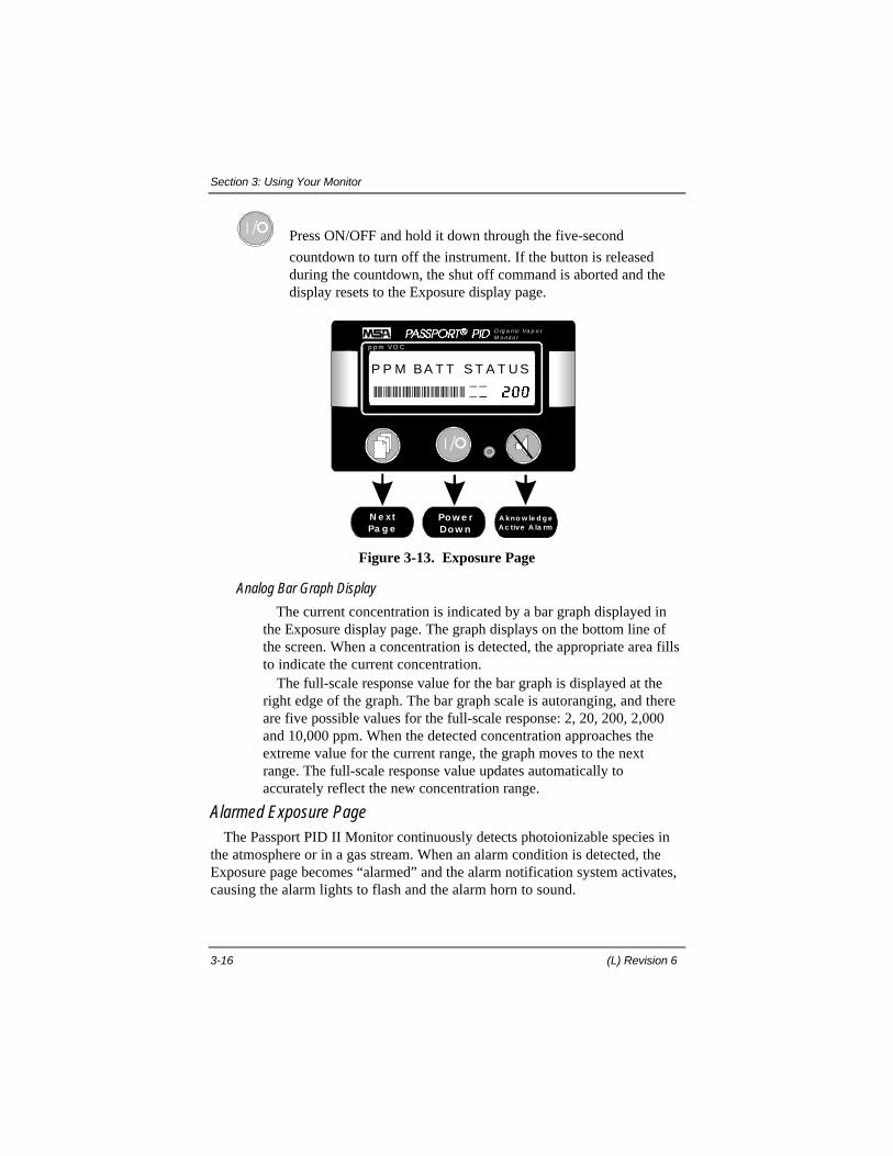
Press ON/OFF and hold it down through the five-second
countdown to turn off the instrument. If the button is releasedduring the countdown, the shut off command is aborted and thedisplay resets to the Exposure display page.
Pow e rDow n
p p m VO C
O rg a n ic Va p o rM o n it o r
N e xtPa g e
A kno w le d g eAc tive A la rm
P P M BA T T S T A T U S
Figure 3-13. Exposure Page
Analog Bar Graph Display
The current concentration is indicated by a bar graph displayed inthe Exposure display page. The graph displays on the bottom line ofthe screen. When a concentration is detected, the appropriate area fillsto indicate the current concentration.
The full-scale response value for the bar graph is displayed at theright edge of the graph. The bar graph scale is autoranging, and thereare five possible values for the full-scale response: 2, 20, 200, 2,000and 10,000 ppm. When the detected concentration approaches theextreme value for the current range, the graph moves to the nextrange. The full-scale response value updates automatically toaccurately reflect the new concentration range.
Alarmed Exposure PageThe Passport PID II Monitor continuously detects photoionizable species in
the atmosphere or in a gas stream. When an alarm condition is detected, theExposure page becomes “alarmed” and the alarm notification system activates,causing the alarm lights to flash and the alarm horn to sound.

Section 3: Using Your Monitor
Passport PID II Monitor, User's Manual 3-17
3.9.Concentration Alarms
When the unit detects a concentration alarm condition:• displayed concentration flashes• alarm horn sounds• alarm lights flash• status message appears indicating which alarm threshold was violated.
N e x tPa g e
N e xtPa g e
N oFunc tio n
Po w e rDo w n
Po w e rDo w n
A c kno w le d g eAla rm
p p m VO C
O rg a n ic Va p o rM o n it o r
p p m VO C
O rg a n ic Va p o rM o n it o r
2 0
1 5 . 5 A L A R M
2 0
1 5 . 5 A L A R M
Figure 3-14. Alarmed Exposure Display – Concentration Alarm

Section 3: Using Your Monitor
3-18 (L) Revision 6
Status Message Concentration Alarm Condition
WARN Indicates a warning level ceiling alarm.
ALARM Indicates an alarm level ceiling alarm.
STEL Indicates that the amount of gas detected by the monitor during the currentperiod is greater than or equal to the STEL limit.
TWA Indicates that the amount of gas detected by the monitor during the currentperiod is greater than or equal to the TWA limit.
Table 3-2. Status Message and Concentration Alarm Indicated
Resetting a Concentration Alarm
Press RESET to acknowledge an alarm.
When a concentration alarm is acknowledged, the alarm horn and flashingred lights cease, however, the status message stays on-screen. If the statusmessage is:“WARN” or “ALARM” Status message cannot be cleared. The status
message remains on-screen until the alarm conditionis no longer detected. If the alarm condition persistsfor more than one minute, the alarm notification(alarm lights, alarm horn) will resume.
“STEL” or “TWA” When a STEL or TWA alarm is acknowledged, thestatus message remains on-screen. The statusmessage can only be cleared if the condition ceasesor if the period (STEL, TWA) is reset. Reset theSTEL alarm period in the STEL page. Reset theTWA alarm period in the TWA page. If the period isnot reset within one minute, the alarm notification(alarm lights, & alarm horn) will resume.
3.10. System Alarms
System alarms indicate that a low battery, obstructed pump or lamp outcondition has been detected. When a system alarm occurs:• alarm horn sounds• alarm lights flash (pump and lamp alarms only)• system status message appears indicating the current alarm.

Section 3: Using Your Monitor
Passport PID II Monitor, User's Manual 3-19
N e xtPa g e
N e xtPa g e
N oFunc tio n
Po w e rDow n
Po w e rDow n
A c k now le d g eA la rm
p p m VO C
O rg a n ic Va p o rM o n it o r
p p m VO C
O rg a n ic Va p o rM o n it o r
2 0
1 5 . 5 L A M P
2 0
1 5 . 5 L A M P
Figure 3-15. Alarmed Exposure Display-Lamp System Alarm
Status Message System Alarm Condition
BATT Indicates a low battery alarm.
LAMP Indicates that the PID lamp is out.
PUMP Indicates that the pump is obstructed.
Table 3-3. Status Message and System Alarm Indicated
Section 3: Using Your Monitor
3-20 (L) Revision 6
BATT System AlarmIf a low battery condition is detected, the alarm horn sounds, and the
“BATT” system status message is displayed on-screen.A BATT alarm indicates that the remaining voltage cannot support the unit
for more than a few minutes of continuous operation. When this condition isreached, the status message in the Battery Condition page updates to “LOW”indicating a warning condition.
Resetting a BATT System Alarm
Press RESET to acknowledge a BATT system alarm.
If the low battery condition is not corrected within one minute, thealarm horn will sound again. A persistent BATT alarm can be resetuntil the remaining voltage reaches the critical (BATTERYSHUTDOWN) alarm level.
BATTERY SHUTDOWN System Alarm When the remaining voltage reaches a critical level, the alarm horn sounds
and the alarm lights are lit. The message:“BATTERY SHUTDOWN”
displays on screen and the display page cannot be changed.This alarm cannot be reset. Automatic shutdown will occur when the
remaining voltage can no longer support the battery alarm function.
WARNING!
If the BATTERY SHUTDOWN alarm sounds:1. Stop using the instrument, the monitor no longer has
enough power to perform alarm functions.2. Leave the survey area immediately and turn off the
instrument.3. Replace or recharge the battery pack before
attempting to operate the unit.Failure to follow this procedure when the BATTERYSHUTDOWN alarm sounds, can result in seriouspersonal injury or death.

Section 3: Using Your Monitor
Passport PID II Monitor, User's Manual 3-21
LAMP System AlarmIf the software detects that the lamp is not lit, the alarm horn sounds, the
alarm lights flash, and the “LAMP” system status message is displayed on-screen.
Resetting a LAMP System Alarm
Press RESET to acknowledge a LAMP system alarm.
When the LAMP alarm is acknowledged in the Alarmed Exposurepage, the alarm horn and flashing red lights cease, however, thestatus message cannot be cleared.If the lamp out condition is not corrected within one minute, thealarm notification (alarm lights & alarm horn) will resume. Thealarm will reoccur every minute until the lamp is relit. Once thelamp is lit, the lamp alarm ceases automatically.
WARNING!
If the LAMP alarm sounds:1. Stop using the instrument, the monitor can no longer
detect volatile organic compounds.2. Leave the survey area immediately and turn off the
instrument.3. Check the lamp cap. It should be finger-tight. (Do notover tighten.) If the lamp alarm persists, do not use theinstrument; contact your MSA Service Technician.Failure to follow this procedure when the LAMP alarmsounds can result in serious personal injury or death.
PUMP System AlarmIf a pump obstruction is detected, or the power to the pump is interrupted, the
alarm horn sounds the alarm lights flash and the “PUMP” system statusmessage is displayed on-screen.
Resetting a PUMP System Alarm
1.Press RESET to acknowledge a PUMP system alarm.

Section 3: Using Your Monitor
3-22 (L) Revision 6
When a PUMP alarm is acknowledged in the Alarmed Exposurepage, the alarm horn and flashing red lights cease, however, the“PUMP” status message remains on-screen.
2. Correct the problem (clear blockage, check electrical connections).
3.Press RESET to clear the “PUMP” status message.
WARNING!
If the PUMP alarm sounds:1. Stop using the instrument, the monitor cannot detect
volatile organic compounds if the inlet flow to thepump is obstructed.
2. Leave the survey area immediately and turn off theinstrument.
3. Determine the status of the pump, by performing thefollowing checks:
- Remove the probe and turn on the instrument. If thepump alarm reoccurs, check the pump module filter,and replace if necessary.
- If the pump alarm does not reoccur, check the watertrap filter in the sample probe, and replace ifnecessary.
If the PUMP alarm persists, do not use the instrument;contact your Service Technician.Failure to follow this procedure when the pump alarmsounds can result in serious personal injury or death.
3.11. Sample Gas Page
The Sample Gas page displays the name of the selected sample gas. Thesample gas selection cannot be changed from this screen. The sample gas canonly be changed while in User Setup mode.
Section 3: Using Your Monitor
Passport PID II Monitor, User's Manual 3-23
Exp osurePa g e
p p m VO C
O rg a n ic Va p o rM o n ito r
N e xtPa g e
N oFunc tio n
I S O B U T Y L E N E
S A M P L E G A S
Figure 3-16. Sample Gas Page
3.12. Battery Condition Page
The Battery Condition page indicates the remaining battery voltage while insurvey mode. The remaining battery voltage is a monitored system parameter,and cannot be changed in any screen.
ExposurePage
ppm VOC
Organic VaporMonitor
NextPage
NoFunction
3 .9 V o k
BA T T ER Y
Figure 3-17. Battery Voltage Page
Battery System AlarmIf a battery alarm is active, a status message in the Battery Condition page
indicates the current alarm level.
Section 3: Using Your Monitor
3-24 (L) Revision 6
Status Message Battery Condition
OK Indicates remaining battery voltage is within an acceptable range.
LOW Indicates the battery can only operate the unit for a few more minutes ofcontinuous operation.
Table 3-4. Status Messages and Battery Condition Indicated
3.13. Date and Time Page
The Date and Time page displays the current time as reported by the internalsystem clock. The date and time can only be changed immediately after thebattery is installed as described on page 3-7, or by using the Data DockingModule and Software accessory.
Exp o sureSc re e n
p p m VO C
O rg a n ic Va p o rM o n ito r
N e xtPa g e
N oFunc tio n
0 9 : 4 8 1 5 a u g 9 6
d a t e & t i m e
Figure 3-18. Date and Time Page
3.14. Peak Reading Page
The Peak Reading page indicates the highest concentration of gas detected bythe monitor since it was turned on or since the peak reading was reset. Thepeak reading period can only be reset in the Peak Reading page.
If the Peak Reading feature is enabled (see Instrument Configuration, onpage 3-5), when the peak reading concentration is greater than or equal to aceiling alarm threshold (warning or alarm), a concentration alarm is initiated.Text indicating the alarm threshold violated (warning or alarm), will bedisplayed in the status message area of the Peak Reading page.
Section 3: Using Your Monitor
Passport PID II Monitor, User's Manual 3-25
Exp o sureSc re e n
p p m VO C
O rg a n ic Va p o rM o n ito r
N e xtPa g e
Re se tPe a k
PEAK READIN G
14 .5
Figure 3-19. Peak Reading Page
Status Message Peak Reading Condition
Blank Indicates that the peak reading displayed is less than the currentwarning and alarm thresholds.
WARN Indicates that the peak reading displayed is greater than or equal to thecurrent warning threshold.
ALARM Indicates that the peak reading displayed is greater than or equal to thecurrent alarm threshold.
Table 3-5. Status Messages and Peak Reading Condition Indicated
Resetting the Peak Reading
Press RESET to reset the peak reading to zero. (See figure 3-20.)
NOTEWhen you turn off the monitor, the peak reading forthe current period is cleared from memory. The peakreading period is reset as part of the instrumentstartup sequence.

Section 3: Using Your Monitor
3-26 (L) Revision 6
Ex p o sureSc re e n
p p m V O C
O rg a n ic Va p o rM o n it o r
N e x tPa g e
Re se t Pe a kRe a d ing to 0
P EA K REA DIN G
14 .5
N oFu nc tio n
p p m V O C
O rg a n ic Va p o rM o n it o r
N O Y ES
RESET P EA K ?
Figure 3-20. Resetting the Peak Reading
3.15. Short Term Exposure Limit (STEL) Page
A STEL reading is the average exposure over a 15-minute period. The STELdisplay page (figure 3-21), indicates the current STEL value, and the timeelapsed since the current period began. Since the 15 minute STEL period is arolling window, until 15 minutes have elapsed, the STEL reading is a trueTWA for the time elapsed
The STEL period is set to zero minutes as part of the startup sequence. It canalso be reset manually. When the STEL period is reset, the unit beginscollecting data for a new 15-minute period. Acknowledged STEL alarms mustbe reset in the STEL display page.

Section 3: Using Your Monitor
Passport PID II Monitor, User's Manual 3-27
Exp o sureSc re e n
p p m VO C
O rg a n ic Va p o rM o n ito r
N e xtPa g e
Re se tSTEL to 0
15 MIN STEL
1.5
Figure 3-21. STEL Page
Status Message STEL Condition
Blank Indicates that the STEL displayed is less than the current STEL alarmthreshold.
ALARM Indicates that the STEL displayed is greater than or equal to the currentSTEL alarm threshold.
Table 3-6. Status Messages and STEL Condition Indicated
STEL AlarmIf the STEL alarm is enabled (see Instrument Configuration on page 3-5), a
STEL alarm occurs when the detected concentration is greater than or equal tothe STEL alarm level. When a STEL alarm is active, the concentration shownin the upper left corner of the STEL display page flashes, and the StatusMessage updates to indicate an alarm condition.
Acknowledging a STEL Alarm
Press RESET in the Alarmed Exposure page to acknowledge an active STEL alarm. The alarm horn and lights cease.
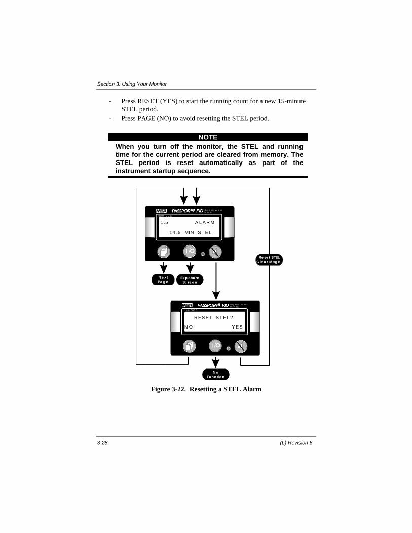
Resetting a STEL PeriodTo completely clear an acknowledged alarm, you must reset the STELperiod:
Press RESET in the STEL page. The display updates to
“RESET STEL?”
Section 3: Using Your Monitor
3-28 (L) Revision 6
- Press RESET (YES) to start the running count for a new 15-minute STEL period.
- Press PAGE (NO) to avoid resetting the STEL period.
NOTEWhen you turn off the monitor, the STEL and runningtime for the current period are cleared from memory. TheSTEL period is reset automatically as part of theinstrument startup sequence.
Exp o sureSc re e n
p p m VO C
O rg a n ic Va p o rM o n it o r
N e xtPa g e
Re se t STELC le a r M sg e .
14 .5 MIN ST EL
1 .5 A L A R M
N oFunc tio n
p p m VO C
O rg a n ic Va p o rM o n it o r
N O Y ES
R ES ET ST EL ?
Figure 3-22. Resetting a STEL Alarm

Section 3: Using Your Monitor
Passport PID II Monitor, User's Manual 3-29
3.16. TWA Page
A TWA reading is the average exposure over an 8-hour period. The TWAreading is a true predictive average, this means that the accumulated exposureis always divided by eight hours.
The TWA page indicates the current TWA concentration and time elapsedsince the current period began. Acknowledged TWA alarms must be reset inthis page.
Exp o sureSc re e n
p p m VO C
O rg a n ic Va p o rM o n ito r
N e xtPa g e
Re se tTWA to 0
7 .5 Ho u R TWA
11.5
Figure 3-23. TWA Page
Status Messages TWA Condition
Blank Indicates that the TWA displayed is less than the current TWA alarmthreshold.
ALARM Indicates that the TWA displayed is greater than or equal to the currentTWA alarm threshold.
Table 3-7. Status Messages and TWA Condition Indicated
TWA AlarmIf the TWA alarm is enabled (see Instrument Configuration on page 3-5), a
TWA alarm occurs when the average concentration of gas detected for thecurrent TWA interval is greater than the eight hour TWA exposure limit.When a TWA alarm is active, the concentration shown in the upper left cornerof the TWA display page flashes, and the Status Message updates to indicate analarm condition.
Section 3: Using Your Monitor
3-30 (L) Revision 6
Acknowledging a TWA Alarm
Press RESET in the Alarmed Exposure page to acknowledge an
active TWA alarm. The alarm horn and lights cease.
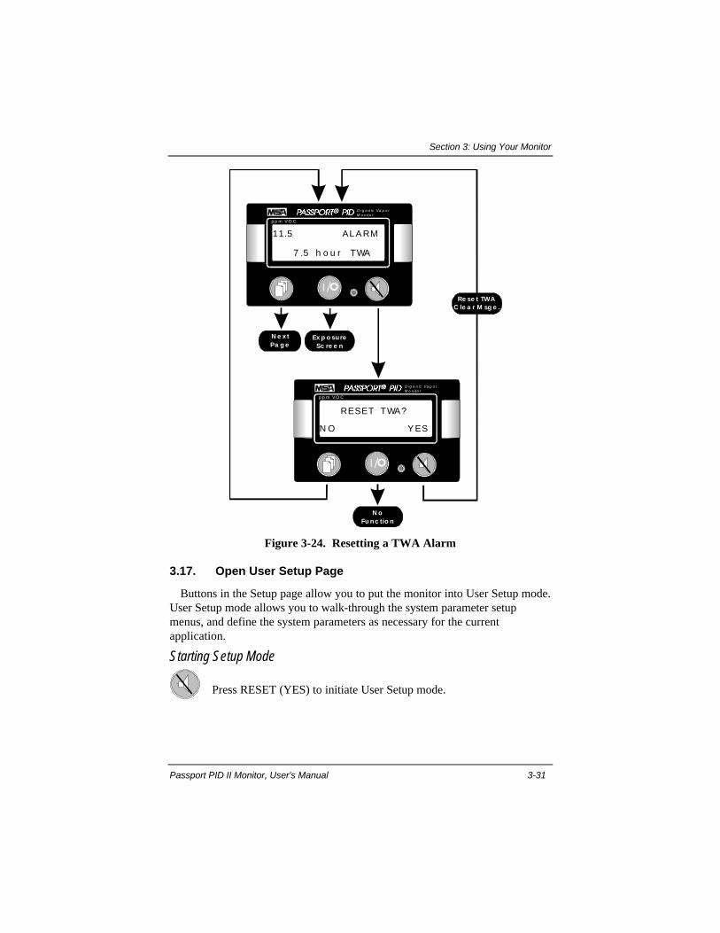
Resetting a TWA PeriodTo completely clear an acknowledged alarm, you must reset the TWAperiod:
Press RESET in the TWA page. The display updates to
“RESET TWA?”
- Press RESET (YES) to start the running count for a new eight hour TWA period.
- Press PAGE (NO) to avoid resetting the TWA period.
NOTEThe TWA period is not reset as part of the instrumentstartup sequence. When you turn off the monitor, theTWA and running time for the current period are stored inthe monitor's memory. The stored running time and TWAare resumed during the next startup. To clear thisinformation after a startup, reset the TWA period.
Section 3: Using Your Monitor
Passport PID II Monitor, User's Manual 3-31
Ex p o sureSc re e n
p p m V O C
O rg a n ic Va p o rM o n ito r
N e x tPa g e
Re se t TWAC le a r M sg e .
7 .5 h o u r TWA
11.5 ALA RM
N oFu nc tio n
p p m V O C
O rg a n ic Va p o rM o n ito r
N O Y ES
RESET TWA?
Figure 3-24. Resetting a TWA Alarm
3.17. Open User Setup Page
Buttons in the Setup page allow you to put the monitor into User Setup mode.User Setup mode allows you to walk-through the system parameter setupmenus, and define the system parameters as necessary for the currentapplication.
Starting Setup Mode
Press RESET (YES) to initiate User Setup mode.

Section 3: Using Your Monitor
3-32 (L) Revision 6
Exp osureSc re e n
p p m VO C
O rg a n ic Va p o rM o n ito r
Use r Se tupM o d e
S E T U P ?
N O Y E S
N e xtPa g e
Figure 3-25. Open User Setup Page
3.18. Instrument Shut Down
Press ON/OFF in the Exposure display page and hold it down through
the five-second countdown to turn off the instrument.If the button is released during the countdown, the shut off commandis aborted and the display resets to the Exposure display page.
Ho ld toTurn O ff
p p m VO C
O rg a n ic Va p o rM o n ito r
N oFunc tio n
N oFunc tion
TO TURN OFF- HOL D
POWER FOR 5 SEC.
Figure 3-26. Power Down Page

Section 3: Using Your Monitor
Passport PID II Monitor, User's Manual 3-33
Battery Pack Removal1. Turn the power off by pressing and holding the ON/OFF button through
the five-second countdown.2. “POWER OFF” appears in the display.3. Turn the "quarter-turn fastener" on the bottom of the instrument in a
counterclockwise direction.4. Disengage the battery pack by sliding it down and away from the battery
contacts as shown in figure 3-27.
BATTERY PA C K
Q UA RTER TURNFA STENER
M O N ITO R BO D Y
Figure 3-27. Battery Pack Removal
3.19 Recharging Nickel-Cadmium (Ni-Cd) Battery Packs
It is not necessary to remove the battery pack from the monitor to charge thebattery. The battery pack can be charged alone or while installed on the unit.1. Plug the charger into an appropriate power source.2. If the battery pack is attached to the monitor, turn off the instrument.3. Insert any MSA Omega charger plug into the jack on the battery pack.4. Be sure the red operating light is on. If the operating light is not on, the
battery pack is not being charged.5. Allow the battery pack to charge undisturbed overnight.
When fully charged, the standard Type A, Ni-Cd battery pack will powerthe Passport PID II Monitor for eight hours of continuous use at 25o C.

Section 3: Using Your Monitor
3-34 (L) Revision 6
Figure 3-28. Single Unit MSA Omega Ni-Cd Charger Accessory(U.S. Version)

Section 4: Defining the Setup Parameters
Passport PID II Monitor, User's Manual 4-1
Section 4. Defining the Setup Parameters
4.1 Setup Mode Display Pages
NOTEOnce you have entered User Setup mode, the display willnot automatically return to the Exposure page. To returnto the Exposure page from a setup screen, you mustpress the ON/OFF button. This will reset the monitor tosurvey mode and open the Exposure page.
4.2.Select Sample Gas
In User Setup Mode, the Select Sample Gas page indicates the currentsample gas. From this page, you can select the desired gas name from aninternal table of 69 gases. When a sample gas name is selected, the responsefactor associated with that gas is used for all subsequent concentrationcalculations in all screens.
The contents of the sample gas table are loaded into the unit at the factory.However, up to ten user-defined entries can be added to the sample gas table tosupport specific applications. These entries can be defined using a personalcomputer and the Passport Data Docking Module accessory. For assistanceloading sample gas names and response factors into the monitor's sample gastable, refer to the Datalogging Software Instructions in the module kit.
Changing the Sample Gas
1. Press RESET to change the sample gas. (If you do not wish tochange the sample gas, press PAGE to go to the Select Labelpage.)
2. Use the PAGE (↓↓) and RESET (↑↑) buttons to scrollthrough the table until the desired sample gas name isdisplayed.
3. Press ON/OFF (OK) to enter the new selection.
Section 4: Defining the Setup Parameters
4-2 (L) Revision 6
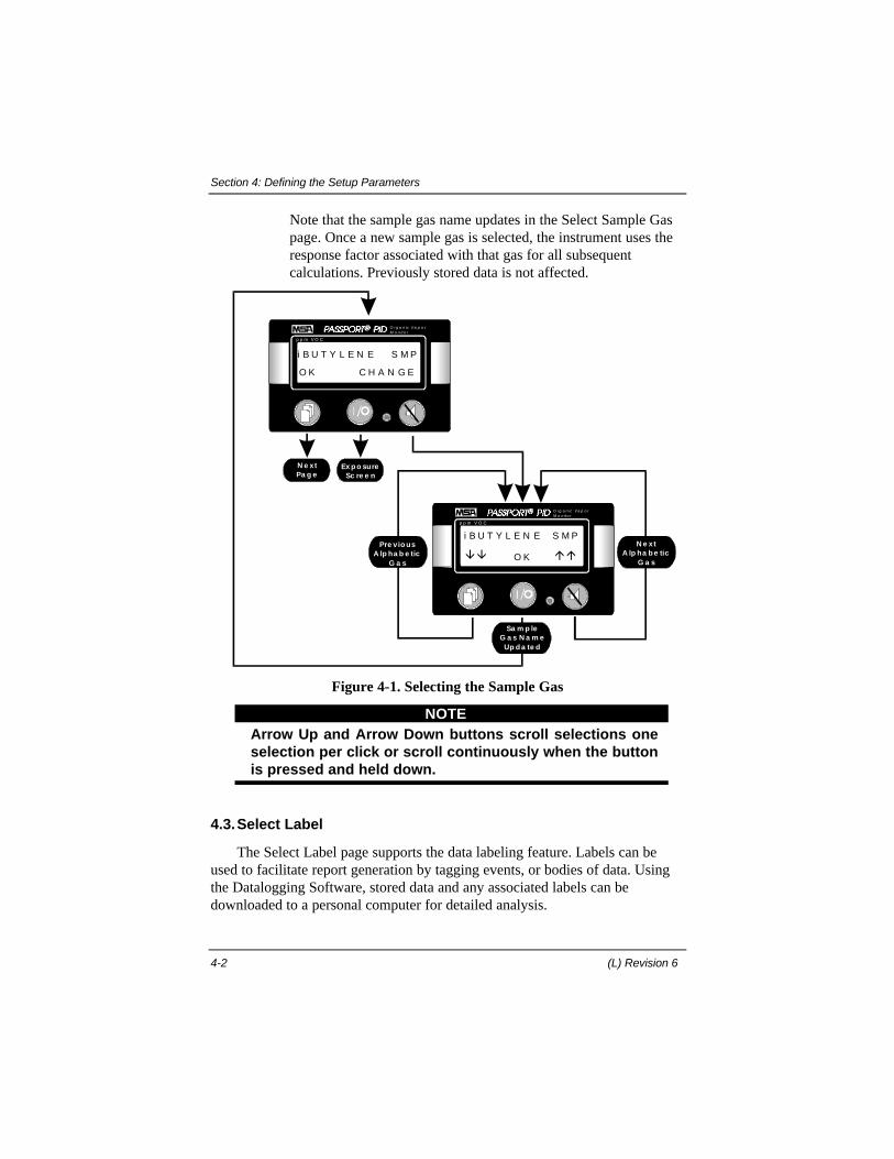
Note that the sample gas name updates in the Select Sample Gaspage. Once a new sample gas is selected, the instrument uses theresponse factor associated with that gas for all subsequentcalculations. Previously stored data is not affected.
p p m V O C
O rg a n ic V a p o rM o n it o r
N e xtPa g e
Ex p o sureSc re e n
i B U T Y L E N E S M P
O K C H A N G E
p p m V O C
O rg a n ic V a p o rM o n it o r
Pre vio usA lp ha b e tic
G a sââ áá
Sa m p leG a s N a m e
Up d a te d
O K
i B U T Y L E N E S M PN e xt
A lp ha b e ticG a s
Figure 4-1. Selecting the Sample Gas
NOTEArrow Up and Arrow Down buttons scroll selections oneselection per click or scroll continuously when the buttonis pressed and held down.
4.3.Select Label
The Select Label page supports the data labeling feature. Labels can beused to facilitate report generation by tagging events, or bodies of data. Usingthe Datalogging Software, stored data and any associated labels can bedownloaded to a personal computer for detailed analysis.
Section 4: Defining the Setup Parameters
Passport PID II Monitor, User's Manual 4-3
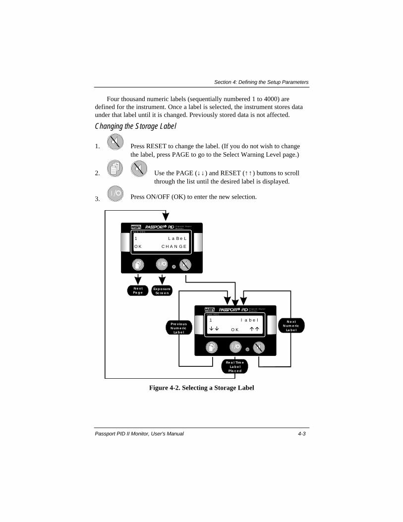
Four thousand numeric labels (sequentially numbered 1 to 4000) aredefined for the instrument. Once a label is selected, the instrument stores dataunder that label until it is changed. Previously stored data is not affected.
Changing the Storage Label
1. Press RESET to change the label. (If you do not wish to changethe label, press PAGE to go to the Select Warning Level page.)
2. Use the PAGE (↓↓) and RESET (↑↑) buttons to scrollthrough the list until the desired label is displayed.
3. Press ON/OFF (OK) to enter the new selection.
p p m V O C
O rg a n ic V a p o rM o n it o r
1 L a B e L
O K C H A N G E
p p m V O C
O rg a n ic V a p o rM o n it o r
ââ ááO K
1 l a b e l
Ne x tPa g e
Exp o sureSc re e n
Pre vio usN um e ric
La b e l
Re a l Tim eLa b e l
Pla c e d
N e xtN um e ric
La b e l
Figure 4-2. Selecting a Storage Label
Section 4: Defining the Setup Parameters
4-4 (L) Revision 6
4.4.Select Warning Level
From the Select Warning Level page, you can view or change the warninglevel threshold for the ceiling concentration alarm. The warning and alarmlevel thresholds represent two distinct levels of alarm.
Changing the Warning Level
1. Press RESET to change the warning alarm level. (If you do notwish to change the warning alarm level, press PAGE to go to theSelect Alarm Level page.)
2. Use the PAGE (↓↓) and RESET (↑↑) buttons to adjustthe value until the desired warning level threshold isdisplayed.
3. Press ON/OFF (OK) to enter the new selection.
If the ceiling alarm feature is turned on, the monitor will initiatean alarm whenever the current concentration is greater than orequal to the threshold value selected for the warning level alarm.
Section 4: Defining the Setup Parameters
Passport PID II Monitor, User's Manual 4-5
p p m V O C
O rg a n ic V a p o rM o n it o r
N e xtPa g e
Ex p o sureSc re e n
5 . 0 0 WA R N L E V
O K C H A N G E
p p m V O C
O rg a n ic V a p o rM o n it o r
De c re a seAla rmVa lue
ââ áá
Ala rmSe tp o intUp d a te d
O K
5 . 0 0 WA R N L E VInc re a se
Ala rmVa lue
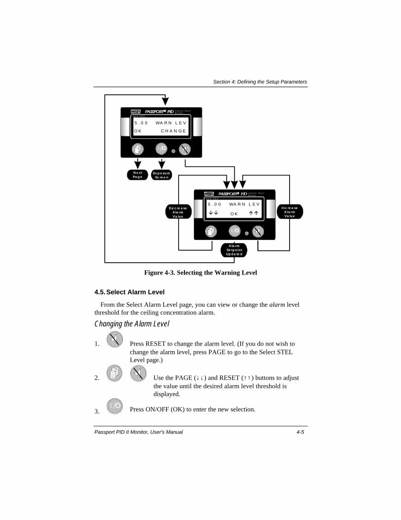
Figure 4-3. Selecting the Warning Level
4.5.Select Alarm Level
From the Select Alarm Level page, you can view or change the alarm levelthreshold for the ceiling concentration alarm.
Changing the Alarm Level
1. Press RESET to change the alarm level. (If you do not wish tochange the alarm level, press PAGE to go to the Select STELLevel page.)
2. Use the PAGE (↓↓) and RESET (↑↑) buttons to adjustthe value until the desired alarm level threshold isdisplayed.
3. Press ON/OFF (OK) to enter the new selection.
Section 4: Defining the Setup Parameters
4-6 (L) Revision 6
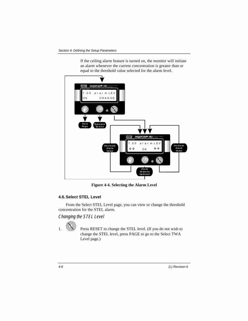
If the ceiling alarm feature is turned on, the monitor will initiatean alarm whenever the current concentration is greater than orequal to the threshold value selected for the alarm level.
p p m V O C
O rg a n ic V a p o rM o n it o r
N e x tPa g e
Exp o sureSc re e n
7 . 0 0 a l a r m L E V
O K C H A N G E
p p m V O C
O rg a n ic V a p o rM o n it o r
De c re a seA la rmVa lue
ââ áá
Ala rmSe tp o intUp d a te d
O K
7 . 0 0 a l a r m L E VIn c re a se
Ala rmVa lue
Figure 4-4. Selecting the Alarm Level
4.6.Select STEL Level
From the Select STEL Level page, you can view or change the thresholdconcentration for the STEL alarm.
Changing the STEL Level
1. Press RESET to change the STEL level. (If you do not wish tochange the STEL level, press PAGE to go to the Select TWALevel page.)
Section 4: Defining the Setup Parameters
Passport PID II Monitor, User's Manual 4-7
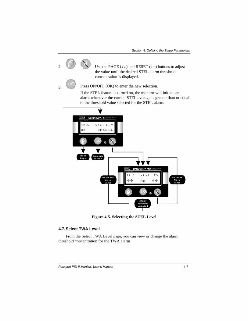
2. Use the PAGE (↓↓) and RESET (↑↑) buttons to adjustthe value until the desired STEL alarm thresholdconcentration is displayed.
3. Press ON/OFF (OK) to enter the new selection.
If the STEL feature is turned on, the monitor will initiate analarm whenever the current STEL average is greater than or equalto the threshold value selected for the STEL alarm.
p p m V O C
O rg a n ic V a p o rM o n it o r
N e x tPa g e
Exp o sureSc re e n
1 2 . 5 s t e l L E V
O K C H A N G E
p p m V O C
O rg a n ic V a p o rM o n it o r
De c re a seA la rmVa lue
ââ áá
Ala rmSe tp o intUp d a te d
O K
1 2 . 5 s t e l L E VIn c re a se
Ala rmVa lue
Figure 4-5. Selecting the STEL Level
4.7.Select TWA Level
From the Select TWA Level page, you can view or change the alarmthreshold concentration for the TWA alarm.

Section 4: Defining the Setup Parameters
4-8 (L) Revision 6
Changing the TWA Level
1. Press RESET to change the TWA level. (If you do not wish tochange the TWA level, press PAGE to exit Setup and return to theExposure page.)
2. Use the PAGE (↓↓) and RESET (↑↑) buttons to adjustthe value until the desired TWA alarm thresholdconcentration is displayed.
3. Press ON/OFF (OK) to enter the new selection.
If the TWA feature is turned on, the monitor will initiate an alarmwhenever the current TWA average is greater than or equal to thethreshold value selected for the TWA alarm.
p p m V O C
O rg a n ic V a p o rM o n it o r
N e xtPa g e
Ex p o sureSc re e n
1 5 . 0 T WA L E V E L
O K C H A N G E
p p m V O C
O rg a n ic V a p o rM o n it o r
De c re a seAla rmVa lue
ââ áá
Ala rmSe tp o intUp d a te d
O K
1 5 . 0 t w a l e v e lInc re a se
Ala rmVa lue
Figure 4-6. Selecting the TWA Level

Section 5: Calibrating
Passport PID II Monitor, User's Manual 5-1
Section 5. Calibrating
5.1. Calibration
WARNING!•• A daily calibration check is part of the routine setup
procedure for this instrument. Failure to perform adaily calibration check and recalibrate if necessary canadversely affect the accuracy of concentrationreadings.
•• Do not attempt to monitor atmospheric conditions withthe unit in calibration mode. The Passport PID IIMonitor cannot perform monitoring functions or issueexposure alarms while the calibration is beingadjusted. To enable the alarm functions, the monitormust be in survey or setup mode.FAILURE TO FOLLOW THESE WARNINGS CANRESULT IN SERIOUS PERSONAL INJURY OR DEATH.
Calibration EquipmentThe monitor can be easily calibrated for any application using calibration
gases of known concentration. To perform a calibration check or calibrate themonitor, you will need calibration tubing and a calibration regulator. Either ofthe configurations shown in figure 5-1 can be used for these procedures. Youwill also need bottled calibration standards. The standard span gas for thePassport PID II Monitor is 100 ppm of isobutylene in air.
C ALIB RA TIO N TUB ING(P.N. 81 4107)
0 -2 LPM R EG U LA TO R(P.N. 69 7344)
C A LIBR ATIO N TUB IN G(P.N . 809066 )
1 .5 LPM REG UL ATO R(P.N. 4 67896 )
C a libra t ion k it w ith f low th roug h Te e v a lve C alib ra tio n k it w ith a d ju sta b le reg u la to r
Figure 5-1. Calibration Equipment
Section 5: Calibrating
5-2 (L) Revision 6
5.2. Calibration Check
1. Be sure you are in a fresh air environment. Press ON/OFF to turn on thePassport PID II Monitor.
2. When the Exposure page opens, read the concentration displayed. If theconcentration is greater than zero, perform a Fresh Air Setup. Following theFresh Air Setup, check the display again to verify that the concentrationreading in the Exposure page is zero ppm.
3. Attach the regulator to the calibration tubing as shown in figure 5-1.4. Attach the regulator to the span gas bottle, and attach the calibration tubing
to the sample inlet port on the monitor.5. Open the valve on the regulator. Allow span gas to flow into the instrument
for at least two minutes, so the unit has sufficient time to stabilize. Note theconcentration reported by the monitor. The displayed concentration shouldbe within 5% of the concentration stated on the bottle.If the span gas reading is not within 5% of the concentration stated on thebottled standard, the Passport PID II Monitor must be calibrated before use.
NOTEIf the monitor fails a Calibration Check, the PID lampmay need to be cleaned. See subsection 6.5Maintenance & Technical Procedures for detailedinstructions on this procedure.
5.3. Calibration Procedure
Figure 5-3 presents the sequence of display pages that support the calibrationprocedure. Each step in the diagram is documented in the followingsubsections.
Initiate Calibration1. If the instrument is running, turn the monitor off. Initiate calibration by
simultaneously pressing and holding the PAGE and RESET buttons. Whilecontinuing to hold the PAGE and RESET buttons, press the ON/OFFbutton. Continue to hold the PAGE and RESET buttons until theinstrument starts up and the display reads:
"CALIBRATE NOW?"
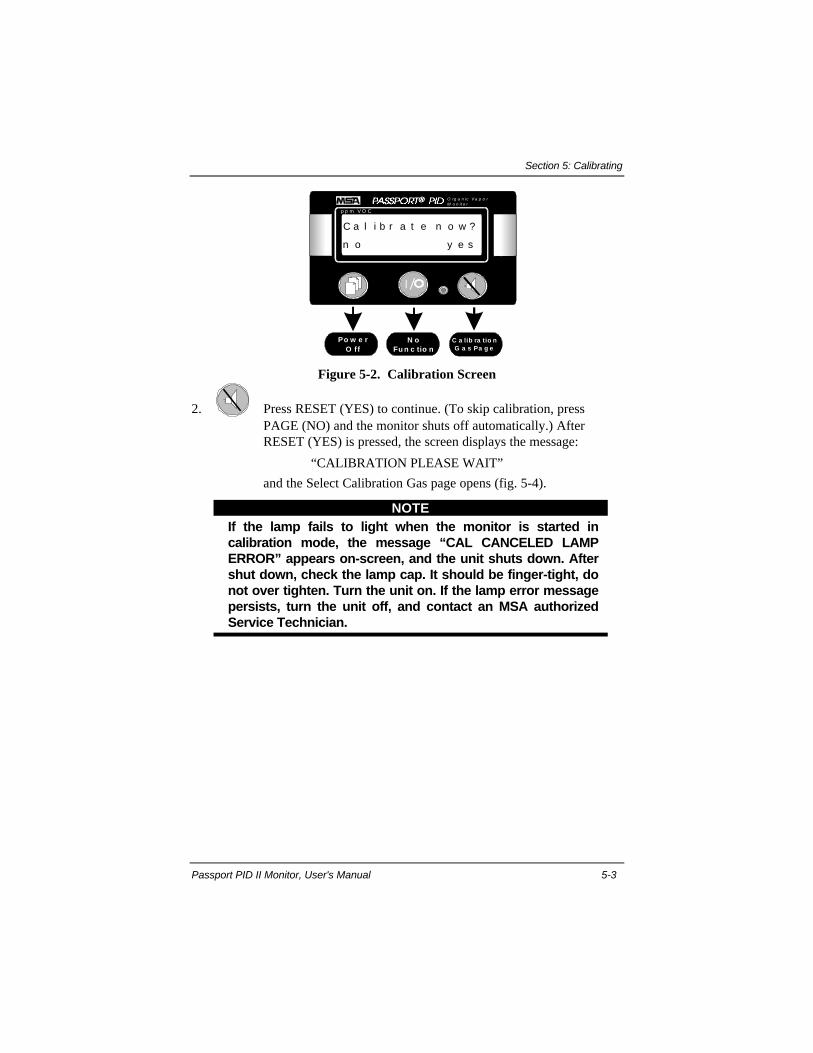
Section 5: Calibrating
Passport PID II Monitor, User's Manual 5-3
N oFu n c tio n
p p m V O C
O rg a n ic V a p o rM o n it o r
Po w e rO ff
C a lib ra tio nG a s Pa g e
C a l i b r a t e n o w ?
n o y e s
Figure 5-2. Calibration Screen
2. Press RESET (YES) to continue. (To skip calibration, pressPAGE (NO) and the monitor shuts off automatically.) AfterRESET (YES) is pressed, the screen displays the message:
“CALIBRATION PLEASE WAIT”
and the Select Calibration Gas page opens (fig. 5-4).
NOTEIf the lamp fails to light when the monitor is started incalibration mode, the message “CAL CANCELED LAMPERROR” appears on-screen, and the unit shuts down. Aftershut down, check the lamp cap. It should be finger-tight, donot over tighten. Turn the unit on. If the lamp error messagepersists, turn the unit off, and contact an MSA authorizedService Technician.
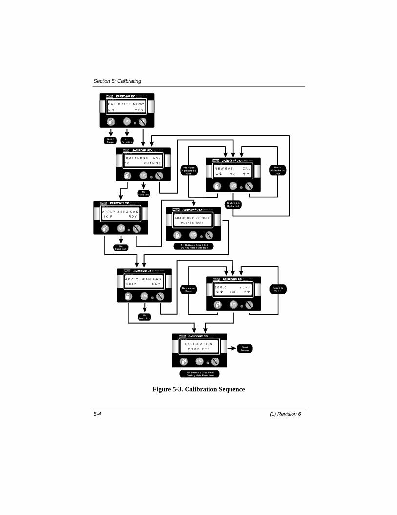
Section 5: Calibrating
5-4 (L) Revision 6
p p m V O C
O rg a n ic V a p o rM o n it o r
i B U T Y L E N E C A L
O K C H A N G E
C A L G a sUp d a te d
p p m V O C
O rg a n ic V a p o rM o n it o r
Pre viousA lp ha be tic
G a s
N e xtA lpha b e tic
G a s
N E W G A S C A L
ââ ááO K
p p m V O C
O rg a n ic V a p o rM o n it o r
A D J U S T I N G Z E R Oe s
P L E A S E WA IT
N oFunc tion
p p m V O C
O rg a n ic V a p o rM o n it o r
A P P L Y Z E R O G A S
S K I P R D Y
p p m V O C
O rg a n ic V a p o rM o n it o r
N e xtPa g e
C A L I B R A T E N O W?
N O Y E S
De c re a seSp a n
Inc re a seSp a n
p p m V O C
O rg a n ic V a p o rM o n it o r
A P P L Y SP A N GA Sp p m V O C
O rg a n ic V a p o rM o n it o r
1 0 0 . 0 s p a n
ââ ááO K
S K I P R D Y
N oFu n c tio n
A ll Butto ns D isa b le dD uring th is Func tion
N oFunc tio n
ShutD ow n
p p m V O C
O rg a n ic V a p o rM o n it o r
C A L I B R A T I O N
C O M P L E T E
N oFu n c tio n
A ll Butto ns D isa b le dD uring th is Func tio n
Figure 5-3. Calibration Sequence
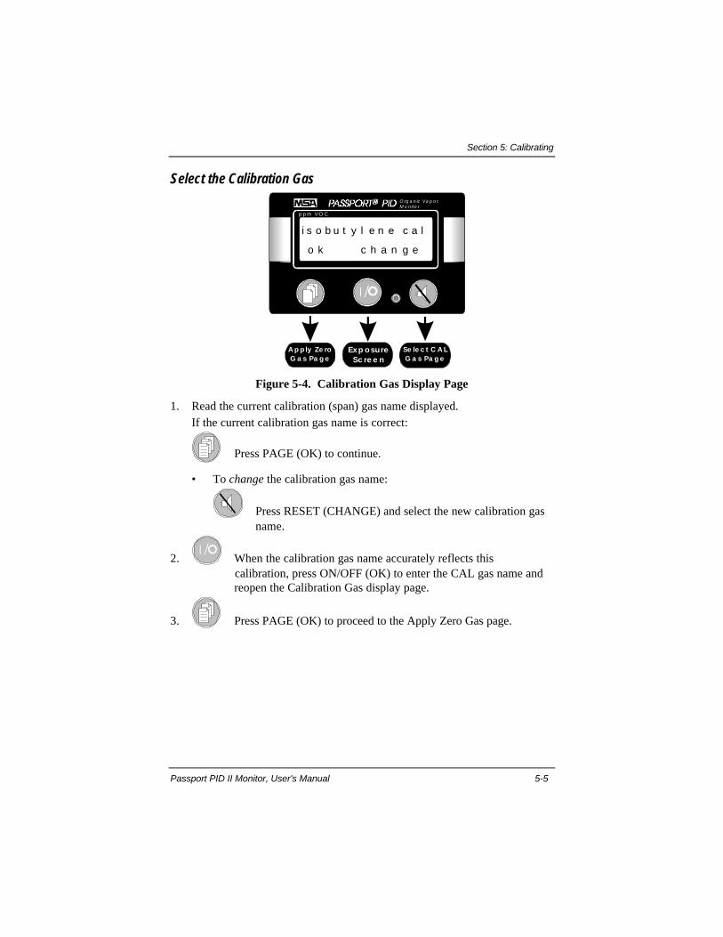
Section 5: Calibrating
Passport PID II Monitor, User's Manual 5-5
Select the Calibration Gas
Exp osureSc re e n
p p m VO C
O rg a n ic Va p o rM o n ito r
A p p ly Ze roG a s Pa g e
Se le c t C A LG a s Pa g e
i s o b u t y l e n e c a l
o k c h a n g e
Figure 5-4. Calibration Gas Display Page
1. Read the current calibration (span) gas name displayed.If the current calibration gas name is correct:
Press PAGE (OK) to continue.
• To change the calibration gas name:
Press RESET (CHANGE) and select the new calibration gas name.
2. When the calibration gas name accurately reflects this calibration, press ON/OFF (OK) to enter the CAL gas name and
reopen the Calibration Gas display page.
3. Press PAGE (OK) to proceed to the Apply Zero Gas page.
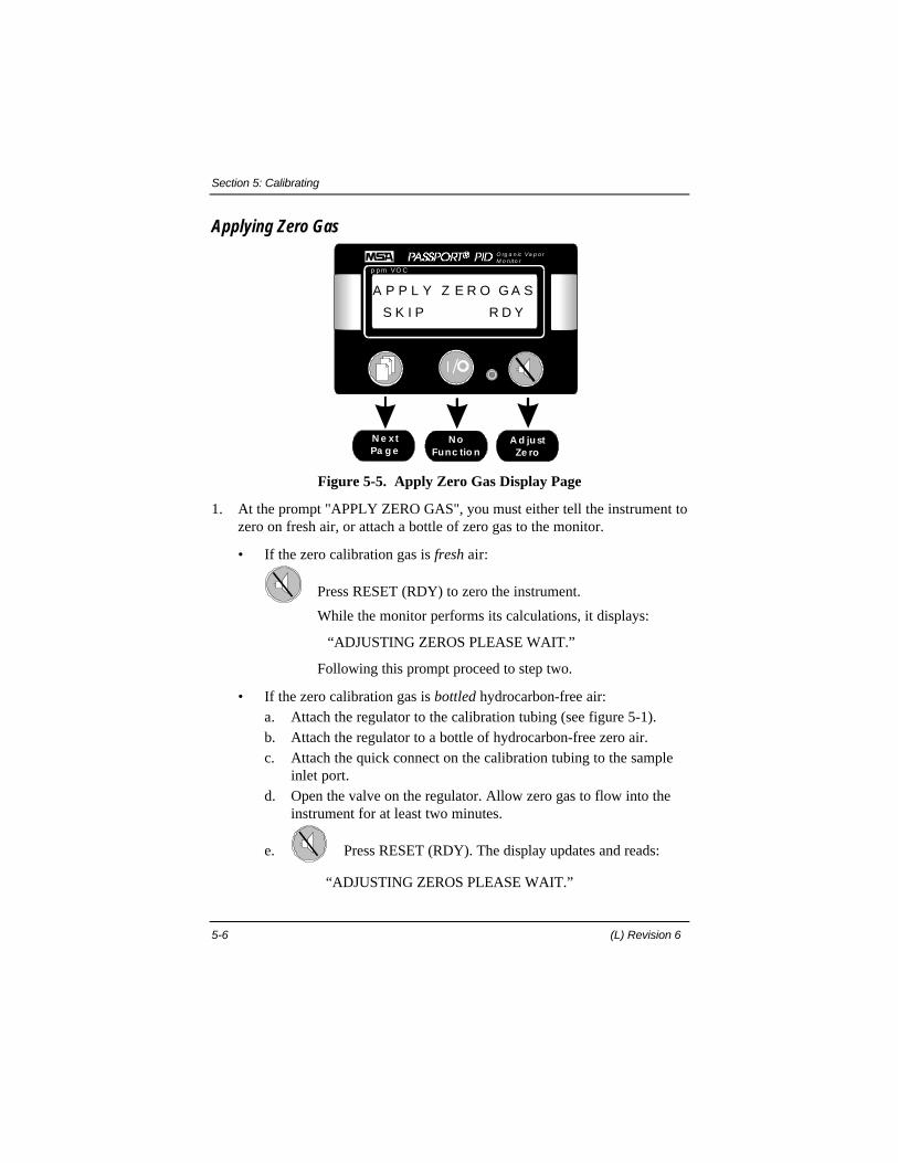
Section 5: Calibrating
5-6 (L) Revision 6
Applying Zero Gas
NoFunc tio n
p p m VO C
O rg a n ic Va p o rM o n ito r
N e xtPa g e
A d justZe ro
A P P L Y Z E R O G A S
S K I P R D Y
Figure 5-5. Apply Zero Gas Display Page
1. At the prompt "APPLY ZERO GAS", you must either tell the instrument tozero on fresh air, or attach a bottle of zero gas to the monitor.
• If the zero calibration gas is fresh air:
Press RESET (RDY) to zero the instrument.
While the monitor performs its calculations, it displays:
“ADJUSTING ZEROS PLEASE WAIT.”
Following this prompt proceed to step two.
• If the zero calibration gas is bottled hydrocarbon-free air:a. Attach the regulator to the calibration tubing (see figure 5-1).b. Attach the regulator to a bottle of hydrocarbon-free zero air.c. Attach the quick connect on the calibration tubing to the sample
inlet port.d. Open the valve on the regulator. Allow zero gas to flow into the
instrument for at least two minutes.
e. Press RESET (RDY). The display updates and reads:
“ADJUSTING ZEROS PLEASE WAIT.”
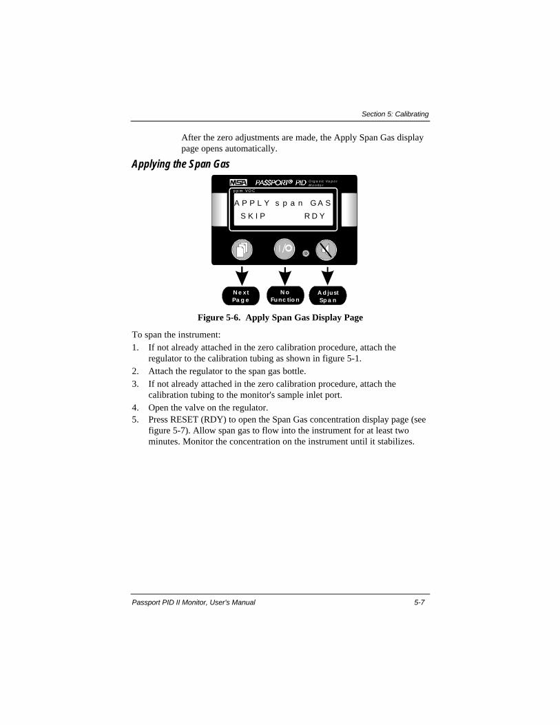
Section 5: Calibrating
Passport PID II Monitor, User's Manual 5-7
After the zero adjustments are made, the Apply Span Gas display page opens automatically.
Applying the Span Gas
N oFunc tio n
p p m VO C
O rg a n ic Va p o rM o n ito r
N e xtPa g e
A d justSp a n
A P P L Y s p a n G A S
S K I P R D Y
Figure 5-6. Apply Span Gas Display Page
To span the instrument:1. If not already attached in the zero calibration procedure, attach the
regulator to the calibration tubing as shown in figure 5-1.2. Attach the regulator to the span gas bottle.3. If not already attached in the zero calibration procedure, attach the
calibration tubing to the monitor's sample inlet port.4. Open the valve on the regulator.5. Press RESET (RDY) to open the Span Gas concentration display page (see
figure 5-7). Allow span gas to flow into the instrument for at least twominutes. Monitor the concentration on the instrument until it stabilizes.

Section 5: Calibrating
5-8 (L) Revision 6
Ente rSp a n
p p m VO C
O rg a n ic Va p o rM o n ito r
De c re a seSp a n
Inc re a seSp a n
1 0 0 . 0 S P A N
ââ ááO K
Figure 5-7. Adjusting the Span Gas Concentration
6. Using the PAGE (ââ) and RESET (áá) buttons, adjust the displayedconcentration until it matches the span gas concentration printed on thespan gas bottle. When the span gas concentration accurately reflects thiscalibration:
Press ON/OFF (OK) to enter the reading. The new reading is stored in memory.
7. A long beep sounds and the display reads:
“CALIBRATION COMPLETE”
and the unit shuts off automatically.8. After calibrating, attach the sampling probe, turn the unit on and briefly
monitor a fresh air environment.
Following a calibration, fresh air should generate a reading of less thanone part per million. If the fresh air reading is greater than one ppm, theprobe and/or sampling line may be contaminated.
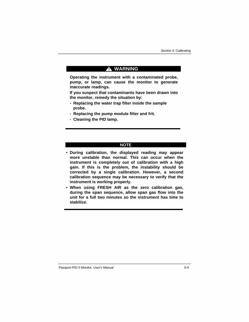
Section 5: Calibrating
Passport PID II Monitor, User's Manual 5-9
WARNING!
Operating the instrument with a contaminated probe,pump, or lamp, can cause the monitor to generateinaccurate readings.If you suspect that contaminants have been drawn intothe monitor, remedy the situation by:- Replacing the water trap filter inside the sample
probe.- Replacing the pump module filter and frit.- Cleaning the PID lamp.
NOTE
•• During calibration, the displayed reading may appearmore unstable than normal. This can occur when theinstrument is completely out of calibration with a highgain. If this is the problem, the instability should becorrected by a single calibration. However, a secondcalibration sequence may be necessary to verify that theinstrument is working properly.
•• When using FRESH AIR as the zero calibration gas,during the span sequence, allow span gas flow into theunit for a full two minutes so the instrument has time tostabilize.
Section 6: Cleaning & Routine Care
Passport PID II Monitor, User's Manual 6-1
Section 6. Cleaning & Routine CareAs with all electronic equipment, the Passport PID II Monitor will operate
only if it is cared for and maintained properly.
WARNING!
Repair or alteration of the Passport PID II OrganicVapor Monitor beyond the scope of these instructionsby anyone other than a person authorized by MSAcould cause the monitor to fail to perform as designed.When needed, use only genuine MSA replacementparts. Substitution of components can impairinstrument performance, alter intrinsic safetycharacteristics, or void agency approvals. Failure tofollow the above can result in serious personal injuryor death.
6.1. Storage
Store your Passport PID II Monitor in a safe, dry place when it is not in use.Be sure that the storage area temperature is between 32 and 104 degreesFahrenheit (0 and 40 degrees Celsius). For long term storage, (more than onemonth) remove the battery pack from the unit.
Clean the monitor's case periodically with a soft cloth dampened with water.
WARNING!After long term storage, perform a Calibration Checkbefore using the instrument. Failure to do so canadversely affect the accuracy of concentration readings.
6.2. Shipping
Remove the battery pack before shipment. If the Passport PID II Monitormust be returned for service, disconnect the battery pack from the instrument,and ship it with the unit.

Section 6: Cleaning & Routine Care
6-2 (L) Revision 6
Pack the Passport PID II Monitor in its original shipping container withsuitable padding. If the original container is unavailable, ask your MSArepresentative for a replacement. An equivalent container may be substituted ifnecessary. In either case, seal the instrument in a plastic bag to protect it frommoisture. Protect the instrument from the rigors of handling with sufficientpadding. Damage due to improper packaging or damage in shipment is notcovered by the instrument's warranty.
6.3 Technical Support
The Passport PID II Monitor is a reliable precision instrument when properlymaintained. If the instrument displays an error message, or becomesinoperative, leave the survey area immediately and turn off the monitor. Do notuse the monitor for protection until the problem is resolved.
The Quick Tab Troubleshooting Guide presented below lists the mostprobable causes of performance problems and approved corrective actions. Ifyour problem is not addressed in the guide, contact an MSA authorized ServiceTechnician. Be sure to have the monitor’s serial number and the softwareversion number handy when calling for technical support.
Call 1-800-MSA-2222 for Technical Support.
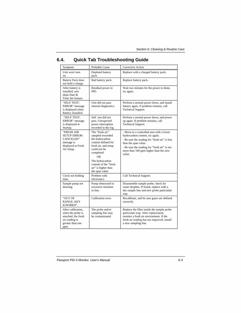
Section 6: Cleaning & Routine Care
Passport PID II Monitor, User's Manual 6-3
6.4. Quick Tab Troubleshooting GuideSymptom Probable Cause Corrective Action
Unit won't turnon.
Depleted batterypack.
Replace with a charged battery pack.
Battery Pack doesnot hold a charge.
Bad battery pack. Replace battery pack.
After battery isinstalled, unitskips Date &Time Set feature.
Residual power inPID.
Wait two minutes for the power to drain,try again.
“SELF TEST:ERROR” messageis displayed whenBattery Installed.
Unit did not passinternal diagnostics.
Perform a normal power down, and installbattery again. If problem remains, callTechnical Support.
“SELF TEST:ERROR” messageis displayed atStartup.
Self test did notpass. Unexpectedpower interruptionrecorded in the log.
Perform a normal power down, and powerup again. If problem remains, callTechnical Support.
“FRESH AIRSETUP ERROR-CANCELED”message isdisplayed at FreshAir Setup.
The “fresh air”sampled exceededthe hydrocarboncontent defined forfresh air, and setupcould not becompleted.
OR
The hydrocarboncontent of the “freshair” is higher thanthe span value.
- Move to a controlled area with a lowerhydrocarbon content, try again.
- Be sure the reading for “fresh air” is lessthan the span value.
- Be sure the reading for “fresh air” is notmore than 100 ppm higher than the zerovalue.
Clock not holdingtime.
Problem withelectronics.
Call Technical Support.
Sample pump notdrawing.
Pump obstructed orexcessive moisturein line.
Disassemble sample probe, check forwater droplets. If found, replace with adry sample line and new probe particulatetrap.
“OUT OFRANGE: KEYIGNORED”.
Calibration error. Recalibrate, and be sure gases are definedcorrectly.
After calibration,when the probe isattached, the freshair reading isgreater than oneppm.
The probe and/orsampling line maybe contaminated.
Replace the filter inside the sample probeparticulate trap. After replacement,monitor a fresh air environment. If thefresh air reading has not improved, installa new sampling line.

Section 6: Cleaning & Routine Care
6-4 (L) Revision 6
6.5. Maintenance & Technical Procedures
Removing and Cleaning the PID LampUsing a lamp that is contaminated with dust, dirt or oily residue can impair
the performance of the instrument. Failure to clean the PID lamp can causeinaccurate readings, jeopardizing monitoring functions.
For the most accurate concentration readings, clean the PID lamp after everyforty hours of use, or whenever the monitor does not respond acceptably to acalibration check. If you are operating the monitor in a high temperature orhigh humidity environment, you may need to clean the lamp more than onceevery 40 hours to maintain optimal performance.
NOTEThoroughly cleaning the PID lamp as described in thisprocedure will restore factory level performance.This procedure can be performed using only methanol.However, depending on the sampling environment thelamp was subjected to, and the amount of residue on thelamp, a methanol wash may not be as effective as thepolishing procedure described in this subsection.
1. Turn off the monitor and disconnect all power to the unit. Unscrew andremove the lamp cap.
2. Grasp the piece of tubing attached to the tip of the lamp. Pull firmly on thetubing until the lamp pops out of its retaining o-ring.
3. Open the PID Polishing kit (P.N. 812155). The kit consists of cleaningimplements, a plastic beaker, a vial of polishing compound, and a bottle oflaboratory grade methanol.
4. Pour approximately 30 ml of methanol into the beaker.5. Moisten a clean cotton swab in the methanol. Dip the damp swab into the
polishing compound so the tip is dusted with compound.
NOTENever dip a used swab into the polishing compound.Doing so will contaminate the vial.
6. Grasp the lamp securely, and use the swab to polish the lamp by scrubbingit in a firm, circular motion. Polish the lamp lens with the swab forapproximately thirty seconds.

Section 6: Cleaning & Routine Care
Passport PID II Monitor, User's Manual 6-5
LAMP
LENS
FELT
PAD
COTTON
SWAB
POLISHING
COMPOUND
Figure 6-1. Cleaning the PID Lamp
7. Using a clean swab, repeat the scrubbing process as described in steps 5and 6, polishing the lamp for an additional thirty seconds.
8. Once the lens is polished, remove the excess by swishing the lens in thebeaker of methanol for at least fifteen seconds. Remove any additionalpolishing compound by scraping it off the lens with a clean swab.
9. Repeat the methanol rinse with a clean swab as described in step 8.10. Dry the lamp lens by spraying it with clean, dry pressurized air. Let the
lamp air-dry for fifteen minutes. *To order convenient, portable cans ofpressurized air, refer to the list of lamp accessories in Table 6-1.
LENSSURFACE
PIDLAMP
Figure 6-2. Removing Debris from the PID Lamp
NOTEDo not use air from an air compressor. Compressed air isnot oil-free. Likewise, do not attempt to remove particlesfrom the lens by blowing on it.

Section 6: Cleaning & Routine Care
6-6 (L) Revision 6
11. Never touch the surface of the lens with your fingers. If accidental contactoccurs, repeat the cleaning procedure before installing the lamp. When dry,insert the lamp into the detector housing and allow it to rest against itsretaining o-ring. Gently but firmly apply inward pressure on the lamp untilit pops back into place.
NOTEDo not apply excess pressure when seating the lamp. Toomuch pressure may damage the detector and/or the lamp.
12. Tighten the lamp cap until it is finger-tight.13. Turn the monitor on in a fresh air environment and let it run for an hour.
This fresh air operating period gives the instrument time to purge anyresidual methanol from the chamber, and stabilize the background reading.
14. Check the system for leaks by plugging the sample inlet port on the back ofthe unit with your clean finger. A pump alarm should initiate promptly.
15. Re-calibrate the instrument (see section 5).
Pump Module Replacement1. Turn the power OFF and remove the battery pack.2. Remove any optional sampling equipment.3. Remove the four screws that mount the pump module.4. Detach the tubing from the detector and disconnect the RS-232 cable.5. Lift the pump module away from the instrument.6. Verify that the pump-to-instrument gasket is in place, and in good
condition.7. Inspect the new pump module. Verify that the pump crank arm on the new
module is centered on the pump eccentric bearing. (Equal amounts ofbearing should show on either side of the crank arm.)
8. Install the new pump module, making sure that the module is well seatedin the gasket.
9. Reattach the RS-232 cable and the detector tubing.10. Secure the pump module in position with the four mounting screws, and
tighten the screws until there is no visible gap between the pump moduleand the instrument case. Do not over-tighten the screws.
11. Verify that the new pump is operational by attempting to initiate a pumpalarm as described in Subsection 3.6 of this manual: Checking the PumpModule.
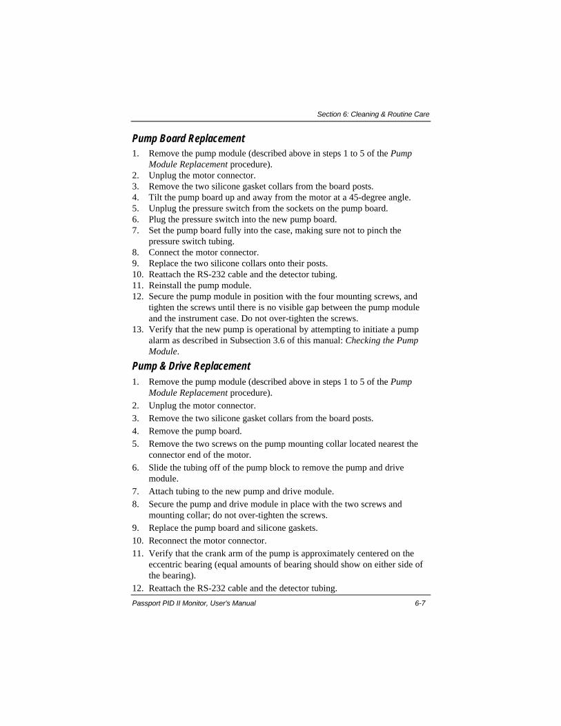
Section 6: Cleaning & Routine Care
Passport PID II Monitor, User's Manual 6-7
Pump Board Replacement1. Remove the pump module (described above in steps 1 to 5 of the Pump
Module Replacement procedure).2. Unplug the motor connector.3. Remove the two silicone gasket collars from the board posts.4. Tilt the pump board up and away from the motor at a 45-degree angle.5. Unplug the pressure switch from the sockets on the pump board.6. Plug the pressure switch into the new pump board.7. Set the pump board fully into the case, making sure not to pinch the
pressure switch tubing.8. Connect the motor connector.9. Replace the two silicone collars onto their posts.10. Reattach the RS-232 cable and the detector tubing.11. Reinstall the pump module.12. Secure the pump module in position with the four mounting screws, and
tighten the screws until there is no visible gap between the pump moduleand the instrument case. Do not over-tighten the screws.
13. Verify that the new pump is operational by attempting to initiate a pumpalarm as described in Subsection 3.6 of this manual: Checking the PumpModule.
Pump & Drive Replacement1. Remove the pump module (described above in steps 1 to 5 of the Pump
Module Replacement procedure).2. Unplug the motor connector.3. Remove the two silicone gasket collars from the board posts.4. Remove the pump board.5. Remove the two screws on the pump mounting collar located nearest the
connector end of the motor.6. Slide the tubing off of the pump block to remove the pump and drive
module.7. Attach tubing to the new pump and drive module.8. Secure the pump and drive module in place with the two screws and
mounting collar; do not over-tighten the screws.9. Replace the pump board and silicone gaskets.10. Reconnect the motor connector.11. Verify that the crank arm of the pump is approximately centered on the
eccentric bearing (equal amounts of bearing should show on either side ofthe bearing).
12. Reattach the RS-232 cable and the detector tubing.
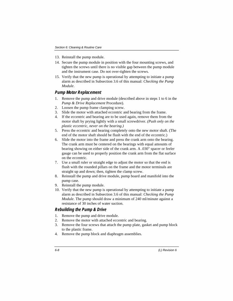
Section 6: Cleaning & Routine Care
6-8 (L) Revision 6
13. Reinstall the pump module.14. Secure the pump module in position with the four mounting screws, and
tighten the screws until there is no visible gap between the pump moduleand the instrument case. Do not over-tighten the screws.
15. Verify that the new pump is operational by attempting to initiate a pumpalarm as described in Subsection 3.6 of this manual: Checking the PumpModule.
Pump Motor Replacement1. Remove the pump and drive module (described above in steps 1 to 6 in the
Pump & Drive Replacement Procedure).2. Loosen the pump frame clamping screw.3. Slide the motor with attached eccentric and bearing from the frame.4. If the eccentric and bearing are to be used again, remove them from the
motor shaft by prying lightly with a small screwdriver. (Push only on theplastic eccentric, never on the bearing.)
5. Press the eccentric and bearing completely onto the new motor shaft. (Theend of the motor shaft should be flush with the end of the eccentric.)
6. Slide the motor into the frame and press the crank arm onto the bearing.The crank arm must be centered on the bearings with equal amounts ofbearing showing on either side of the crank arm. A .030" spacer or feelergauge can be used to properly position the crank arm from the flat surfaceon the eccentric.
7. Use a small ruler or straight edge to adjust the motor so that the end isflush with the rounded pillars on the frame and the motor terminals arestraight up and down; then, tighten the clamp screw.
8. Reinstall the pump and drive module, pump board and manifold into thepump case.
9. Reinstall the pump module.10. Verify that the new pump is operational by attempting to initiate a pump
alarm as described in Subsection 3.6 of this manual: Checking the PumpModule. The pump should draw a minimum of 240 ml/minute against aresistance of 30 inches of water suction.
Rebuilding the Pump & Drive1. Remove the pump and drive module.2. Remove the motor with attached eccentric and bearing.3. Remove the four screws that attach the pump plate, gasket and pump block
to the plastic frame.4. Remove the pump block and diaphragm assemblies.
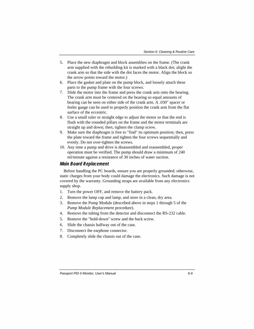
Section 6: Cleaning & Routine Care
Passport PID II Monitor, User's Manual 6-9
5. Place the new diaphragm and block assemblies on the frame. (The crankarm supplied with the rebuilding kit is marked with a black dot; alight thecrank arm so that the side with the dot faces the motor. Align the block sothe arrow points toward the motor.)
6. Place the gasket and plate on the pump block, and loosely attach theseparts to the pump frame with the four screws.
7. Slide the motor into the frame and press the crank arm onto the bearing.The crank arm must be centered on the bearing so equal amounts ofbearing can be seen on either side of the crank arm. A .030" spacer orfeeler gauge can be used to properly position the crank arm from the flatsurface of the eccentric.
8. Use a small ruler or straight edge to adjust the motor so that the end isflush with the rounded pillars on the frame and the motor terminals arestraight up and down; then, tighten the clamp screw.
9. Make sure the diaphragm is free to "find" its optimum position; then, pressthe plate toward the frame and tighten the four screws sequentially andevenly. Do not over-tighten the screws.
10. Any time a pump and drive is disassembled and reassembled, properoperation must be verified. The pump should draw a minimum of 240ml/minute against a resistance of 30 inches of water suction.
Main Board ReplacementBefore handling the PC boards, ensure you are properly grounded; otherwise,
static charges from your body could damage the electronics. Such damage is notcovered by the warranty. Grounding straps are available from any electronicssupply shop.1. Turn the power OFF, and remove the battery pack.2. Remove the lamp cap and lamp, and store in a clean, dry area.3. Remove the Pump Module (described above in steps 1 through 5 of the
Pump Module Replacement procedure).4. Remove the tubing from the detector and disconnect the RS-232 cable.5. Remove the "hold-down" screw and the back screw.6. Slide the chassis halfway out of the case.7. Disconnect the earphone connector.8. Completely slide the chassis out of the case.

Section 6: Cleaning & Routine Care
6-10 (L) Revision 6
Figure 6-3. Removing the Chassis
9. Remove the four main electronics board mounting screws.10. Turn the instrument over, and lift the main board up to a 45-degree angle;
disconnect the power connector.
Figure 6-4. Location of Mounting Screws & Power Connector
11. Lift up the board up to approximately 90 degrees, and remove theinterconnect board and the keypad connector.
12. Remove the board.13. Set the switches on the new main electronics board to the same positions as
those set on the old main electronics board.14. Insert the new main electronics board.15. Connect the interconnect board and the keypad connector.16. Connect the power connector.17. Fasten the four module-board mounting screws.18. Slide the chassis halfway into the case.19. Connect the earphone connector.

Section 6: Cleaning & Routine Care
Passport PID II Monitor, User's Manual 6-11
20. Slide the chassis completely into the case.21. Replace the "hold-down" screw and back screw.22. Install the pump module, and reattach the RS-232 cable and the detector
tubing.23. Clean, and reinstall the PID lamp. Replace the lamp cap.24. Replace the battery pack.25. Perform a complete calibration of the Passport PID II Monitor.26. Verify the alarm set points, adjust if necessary.
Display Module Replacement1. Turn the power OFF, and remove the battery pack.2. Remove the lamp cap and lamp, and store in a clean, dry area.3. Remove the Pump Module (described above in steps 1 through 5 of the
Pump Module Replacement procedure).4. Detach the tubing from the detector and disconnect the RS-232 cable.5. Remove the "hold-down" screw, and the back screw.6. Slide the chassis halfway out of the case.7. Disconnect the earphone connector.8. Completely slide the chassis out of the case.9. Turn the instrument over, and remove the four mounting screws.10. Lift the main board up to a 45-degree angle; disconnect the power
connector. (See figure 3-4.)11. Lift the main board up to approximately 90 degrees, and remove the
interconnect board and the keypad connector.12. Remove the two screws holding the display to the chassis. Remove the four
screws holding the display module to the face piece.13. Remove the display module.14. Install the new display module.15. Fasten the display mounting screws.16. Connect the keypad connector and the interconnect board.17. Connect the power connector.18. Replace the four module mounting screws.19. Slide the chassis halfway into the case.20. Connect the earphone connector.21. Slide the chassis completely into the case.22. Replace the "hold-down" screw, and the back screw.23. Clean, and reinstall the PID lamp. Replace the lamp cap.24. Install the pump module. Reattach the RS-232 cable and the detector
tubing.25. Replace the battery pack.26. Perform a complete calibration of the Passport PID II Monitor.
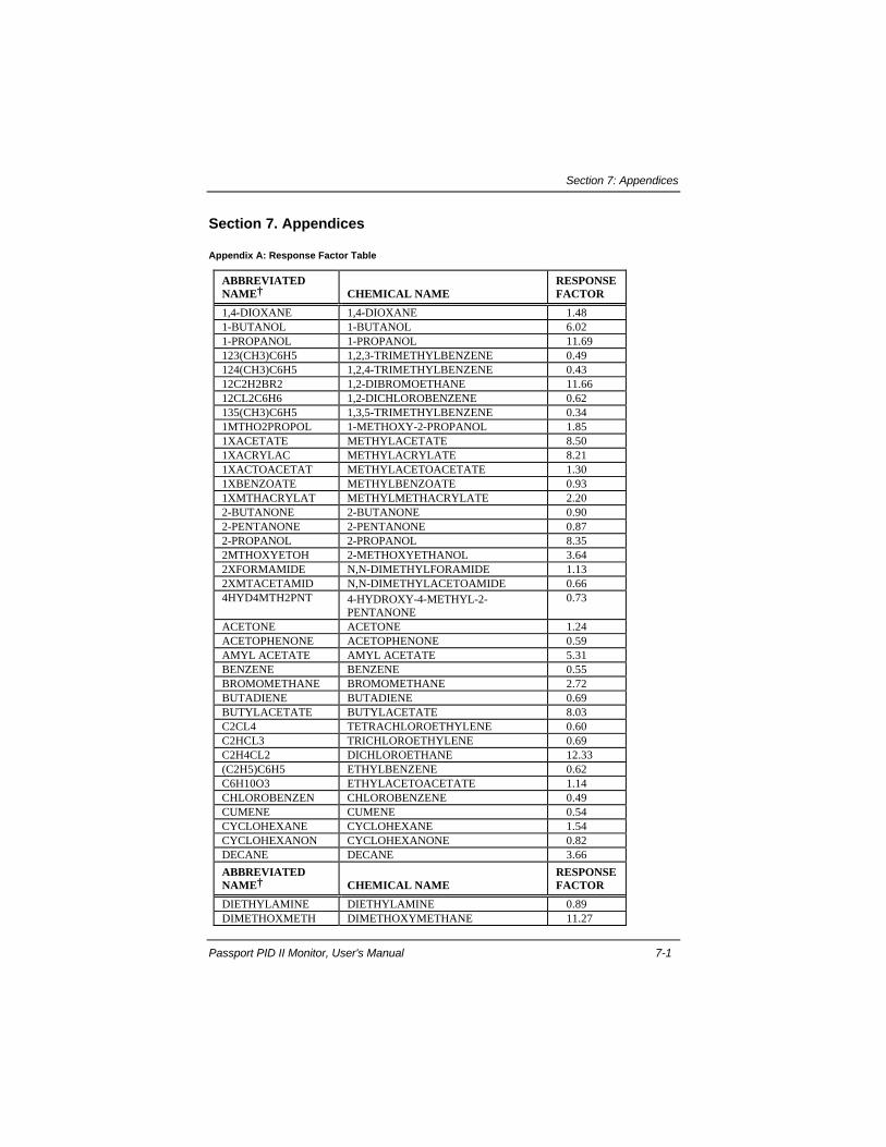
Section 7: Appendices
Passport PID II Monitor, User's Manual 7-1
Section 7. Appendices
Appendix A: Response Factor Table
ABBREVIATEDNAME† CHEMICAL NAME
RESPONSEFACTOR
1,4-DIOXANE 1,4-DIOXANE 1.481-BUTANOL 1-BUTANOL 6.021-PROPANOL 1-PROPANOL 11.69123(CH3)C6H5 1,2,3-TRIMETHYLBENZENE 0.49124(CH3)C6H5 1,2,4-TRIMETHYLBENZENE 0.4312C2H2BR2 1,2-DIBROMOETHANE 11.6612CL2C6H6 1,2-DICHLOROBENZENE 0.62135(CH3)C6H5 1,3,5-TRIMETHYLBENZENE 0.341MTHO2PROPOL 1-METHOXY-2-PROPANOL 1.851XACETATE METHYLACETATE 8.501XACRYLAC METHYLACRYLATE 8.211XACTOACETAT METHYLACETOACETATE 1.301XBENZOATE METHYLBENZOATE 0.931XMTHACRYLAT METHYLMETHACRYLATE 2.202-BUTANONE 2-BUTANONE 0.902-PENTANONE 2-PENTANONE 0.872-PROPANOL 2-PROPANOL 8.352MTHOXYETOH 2-METHOXYETHANOL 3.642XFORMAMIDE N,N-DIMETHYLFORAMIDE 1.132XMTACETAMID N,N-DIMETHYLACETOAMIDE 0.664HYD4MTH2PNT 4-HYDROXY-4-METHYL-2-
PENTANONE0.73
ACETONE ACETONE 1.24ACETOPHENONE ACETOPHENONE 0.59AMYL ACETATE AMYL ACETATE 5.31BENZENE BENZENE 0.55BROMOMETHANE BROMOMETHANE 2.72BUTADIENE BUTADIENE 0.69BUTYLACETATE BUTYLACETATE 8.03C2CL4 TETRACHLOROETHYLENE 0.60C2HCL3 TRICHLOROETHYLENE 0.69C2H4CL2 DICHLOROETHANE 12.33(C2H5)C6H5 ETHYLBENZENE 0.62C6H10O3 ETHYLACETOACETATE 1.14CHLOROBENZEN CHLOROBENZENE 0.49CUMENE CUMENE 0.54CYCLOHEXANE CYCLOHEXANE 1.54CYCLOHEXANON CYCLOHEXANONE 0.82DECANE DECANE 3.66
ABBREVIATEDNAME† CHEMICAL NAME
RESPONSEFACTOR
DIETHYLAMINE DIETHYLAMINE 0.89DIMETHOXMETH DIMETHOXYMETHANE 11.27
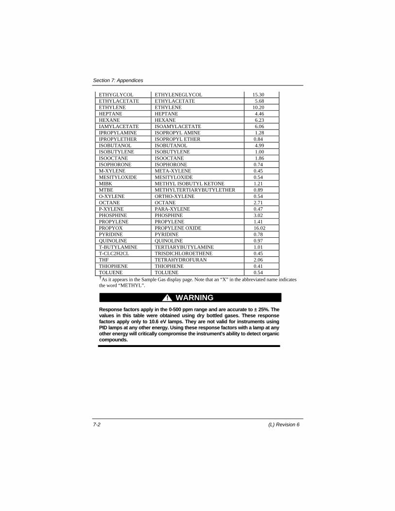
Section 7: Appendices
7-2 (L) Revision 6
ETHYGLYCOL ETHYLENEGLYCOL 15.30ETHYLACETATE ETHYLACETATE 5.68ETHYLENE ETHYLENE 10.20HEPTANE HEPTANE 4.46HEXANE HEXANE 6.23IAMYLACETATE ISOAMYLACETATE 6.06IPROPYLAMINE ISOPROPYL AMINE 1.28IPROPYLETHER ISOPROPYL ETHER 0.84ISOBUTANOL ISOBUTANOL 4.99ISOBUTYLENE ISOBUTYLENE 1.00ISOOCTANE ISOOCTANE 1.86ISOPHORONE ISOPHORONE 0.74M-XYLENE META-XYLENE 0.45MESITYLOXIDE MESITYLOXIDE 0.54MIBK METHYL ISOBUTYL KETONE 1.21MTBE METHYLTERTIARYBUTYLETHER 0.89O-XYLENE ORTHO-XYLENE 0.54OCTANE OCTANE 2.71P-XYLENE PARA-XYLENE 0.47PHOSPHINE PHOSPHINE 3.02PROPYLENE PROPYLENE 1.41PROPYOX PROPYLENE OXIDE 16.02PYRIDINE PYRIDINE 0.78QUINOLINE QUINOLINE 0.97T-BUTYLAMINE TERTIARYBUTYLAMINE 1.01T-CLC2H2CL TRISDICHLOROETHENE 0.45THF TETRAHYDROFURAN 2.06THIOPHENE THIOPHENE 0.41TOLUENE TOLUENE 0.54†As it appears in the Sample Gas display page. Note that an “X” in the abbreviated name indicatesthe word “METHYL”.
WARNING!
Response factors apply in the 0-500 ppm range and are accurate to ± 25%. Thevalues in this table were obtained using dry bottled gases. These responsefactors apply only to 10.6 eV lamps. They are not valid for instruments usingPID lamps at any other energy. Using these response factors with a lamp at anyother energy will critically compromise the instrument's ability to detect organiccompounds.

Section 7: Appendices
Passport PID II Monitor, User's Manual 7-3
Appendix B: Additional Response Factors
Measurement of ammonia, 1.4-Butanediol, ethylene oxide or, othersubstances having a response factor greater than 15.99.
When using the Passport PID II Monitor for ammonia, 1,4-Butanediol,ethylene oxide or, other substances having a response factor greater than theinstrument limit of 15.99, it is recommended that the user calibrate theinstrument with the gas of interest. If that approach is not feasible, the usermust interpolate the reading in order to determine the actual concentration ofthe substance present. That is, the user must multiply the displayed reading byanother factor to compensate for the lower response factor for which theinstrument must be set. It is important that users correctly interpret thereadings obtained, as the displayed reading will be lower than the actualconcentration present.
An Ethylene Oxide Example:An MSA PID instrument calibrated with 100-ppm isobutylene has a response
factor for ethylene oxide of 21.28. However, the highest response factor thatcan be programmed into the PID is 15.99. Therefore, when the PID iscalibrated with isobutylene and the sample gas page is set to read ppm ethyleneoxide, the most accurate indication of ethylene oxide concentration can beobtained by setting the instrument response factor to 15.99 and multiplying theinstrument reading by 1.33. However, some users may find it easier to set theinstrument response factor to one half (10.64) of the actual response factor andmultiply the displayed value by 2.
An Ammonia Example:An MSA PID instrument calibrated with 100-ppm isobutylene has a response
factor for ammonia of 16.62. However, the highest response factor that can beprogrammed into the PID is 15.99. Therefore, when the PID is calibrated withisobutylene and the sample gas page is set to read ppm ammonia, a moreaccurate indication of ammonia concentration can be obtained by setting theinstrument response factor to 15.99 and multiplying the instrument reading by1.04. However, some users may find it easier to set the instrument responsefactor to one half (8.31) of the actual response factor for ammonia and multiplythe displayed value by 2.

Section 7: Appendices
7-4 (L) Revision 6
As stated above, it is recommended that when using an MSA PID instrumentfor monitoring compounds with response factors in excess of 15.99, theinstrument be calibrated with the compound of interest to avoid the need to usea secondary factor to determine the actual concentration.
Contact MSA Customer Service at 1-800-MSA-2222 with any questionregarding the above information.
The additional response factors listed here in Appendix B have beendetermined by MSA Chemists using the Passport PID II Monitor. The listingconsists of response factors for several common industrial chemicals that arenot preprogrammed into the instrument.
Using your IBM compatible PC with the Data Logging Software and DataDocking Module, you can add a response factor from this listing to themonitor’s internal gas table. Consult the Passport PID Data Logging SoftwareUser’s Manual for specific instructions.
CHEMICAL NAME RESPONSE FACTOR
ACETALDEHYDE 11.00ALLYL ALCOHOL 2.92AMMONIA 16.621,4-BUTANEDIOL 37.20BUTOXYETHANOL 1.44DIMETHYLFORMAMIDE 1.10EPICHLOROHYDRIN 13.00ETHANOL 10.70ETHYLENE 10.2ETHYLENE OXIDE 21.28GAMMA BUTYROLACTONE 3.01HYDRAZINE 2.60HYDROGEN SULFIDE 6.25ISOPROPANOL 8.66JET A & JP8 FUEL 3.00JET A1 FUEL 3.80JP 5 FUEL 2.90JP 8 FUEL 2.90METHANOL (11.7 LAMP) 5.56METHYL BENZYL ALCOHOL 7.12METHYLENE CHLORIDE (11.7 LAMP) 2.04METHYL ETHYL KETONE (MEK) 0.97MONOMETHYLAMINE 2.07N-METHYL PYRROLIDONE 1.81PHENOL 8.90PHENYL ETHYL ALCOHOL 9.042-PICOLINE 0.72
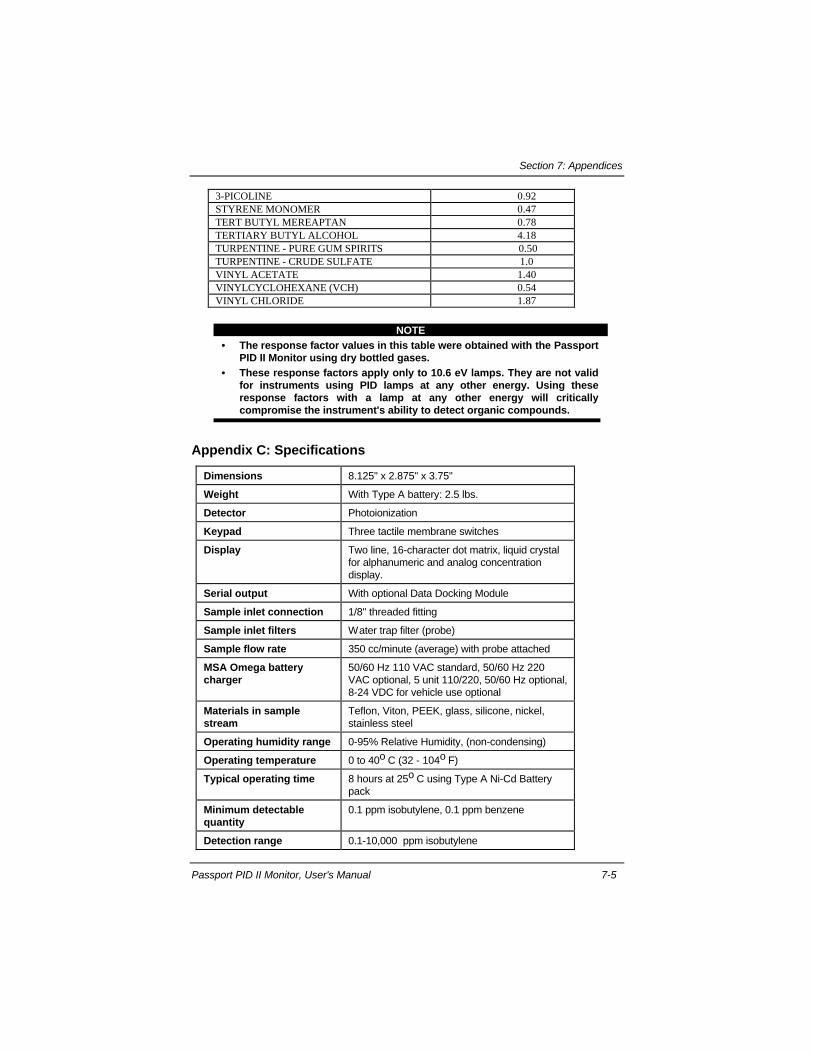
Section 7: Appendices
Passport PID II Monitor, User's Manual 7-5
3-PICOLINE 0.92STYRENE MONOMER 0.47TERT BUTYL MEREAPTAN 0.78TERTIARY BUTYL ALCOHOL 4.18TURPENTINE - PURE GUM SPIRITS 0.50TURPENTINE - CRUDE SULFATE 1.0VINYL ACETATE 1.40VINYLCYCLOHEXANE (VCH) 0.54VINYL CHLORIDE 1.87
NOTE• The response factor values in this table were obtained with the Passport
PID II Monitor using dry bottled gases.• These response factors apply only to 10.6 eV lamps. They are not valid
for instruments using PID lamps at any other energy. Using theseresponse factors with a lamp at any other energy will criticallycompromise the instrument's ability to detect organic compounds.
Appendix C: Specifications
Dimensions 8.125" x 2.875" x 3.75"
Weight With Type A battery: 2.5 lbs.
Detector Photoionization
Keypad Three tactile membrane switches
Display Two line, 16-character dot matrix, liquid crystalfor alphanumeric and analog concentrationdisplay.
Serial output With optional Data Docking Module
Sample inlet connection 1/8" threaded fitting
Sample inlet filters Water trap filter (probe)
Sample flow rate 350 cc/minute (average) with probe attached
MSA Omega batterycharger
50/60 Hz 110 VAC standard, 50/60 Hz 220VAC optional, 5 unit 110/220, 50/60 Hz optional,8-24 VDC for vehicle use optional
Materials in samplestream
Teflon, Viton, PEEK, glass, silicone, nickel,stainless steel
Operating humidity range 0-95% Relative Humidity, (non-condensing)
Operating temperature 0 to 40o C (32 - 104o F)
Typical operating time 8 hours at 25o C using Type A Ni-Cd Batterypack
Minimum detectablequantity
0.1 ppm isobutylene, 0.1 ppm benzene
Detection range 0.1-10,000 ppm isobutylene

Section 7: Appendices
7-6 (L) Revision 6
Response Time withprobe
6 seconds or less to 90% of final reading
Repeatability ± 1 %
Appendix D: Options and Accessories
Table 7-1. Battery Packs & Chargers
Description Part Number
Battery Pack, Ni-Cd C Cell Rechargeable, Type A 496990
Battery Pack, Ni-Cd, D Cell, Rechargeable, Type B 800527
Battery Pack, Alkaline C Cell 800526
110V 50/60 Hz Battery Charger 494716
220V 50/60 Hz Battery Charger 495965
110V/220V 50/60 Hz 5 Unit Battery Charger 801759
Table 7-2. Calibration Equipment
Description Part Number
Regulator, 1.5 LPM 467896
Calibration Tubing (with T-valve, for use with 1.5 LPM
regulator P.N. 467896)
809066
Calibration Tubing (for use with 0-2 LPM regulator, P.N.
697344)
814107
Quick-connect Calibration Adapter 636246
Zero Gas - Air 801050
Calibration Cylinder 100 ppm isobutylene in air 494450
Calibration regulator, demands 710288
Table 7-3. Lamps & Accessories
Description Part Number
Lamp - 10.6 eV 815251
Lamp - 11.7 eV 655531
Lamp Cap 815256
Lamp Cleaning Kit 812155
Methanol Refill Kit 655650
Cleaning Kit Refill 655651

Section 7: Appendices
Passport PID II Monitor, User's Manual 7-7
Table 7-4. Filtering System Replacement Parts
Description Part Number
Water Trap (Teflon) Filter 636244
Pump Module 655771
Table 7-5. Optional Equipment
Description Part Number
Belt Bracket 496366
Belt Loop & Swivel 803412
Earphone Assembly 633722
Wrist Strap 474407
Hand/Wrist Strap (fits boot and carrying case) 812834
Harness 474555
Passport PID Monitor Data Docking Module 804679
Passport PID II Monitor User's Manual 815253
Passport PID II Monitor Instruction Card 815254
Remote Alarm - Low (90 dB) Output 800992
Remote Alarm - High (105 dB) Output 800991
Shock Boot (fits Alkaline battery pack) 806748
Shock Boot (fits Ni-Cd battery packs, Type A & B) 806750
Soft Carrying Case with Harness 812833
Holster for using PID II with pistol grip 711006
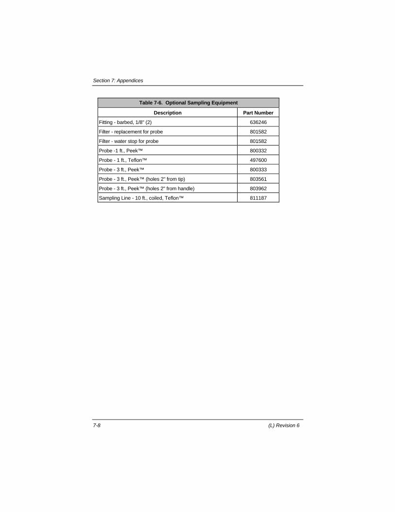
Section 7: Appendices
7-8 (L) Revision 6
Table 7-6. Optional Sampling Equipment
Description Part Number
Fitting - barbed, 1/8" (2) 636246
Filter - replacement for probe 801582
Filter - water stop for probe 801582
Probe -1 ft., Peek™ 800332
Probe - 1 ft., Teflon™ 497600
Probe - 3 ft., Peek™ 800333
Probe - 3 ft., Peek™ (holes 2" from tip) 803561
Probe - 3 ft., Peek™ (holes 2" from handle) 803962
Sampling Line - 10 ft., coiled, Teflon™ 811187
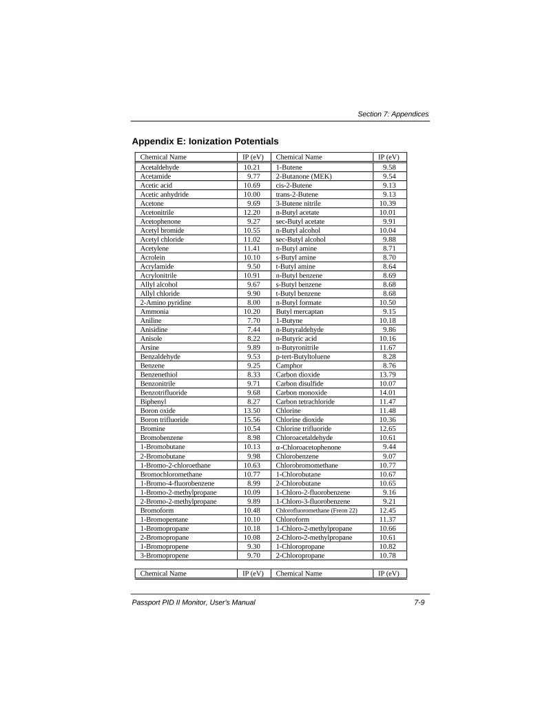
Section 7: Appendices
Passport PID II Monitor, User's Manual 7-9
Appendix E: Ionization Potentials
Chemical Name IP (eV) Chemical Name IP (eV)
Acetaldehyde 10.21 1-Butene 9.58Acetamide 9.77 2-Butanone (MEK) 9.54Acetic acid 10.69 cis-2-Butene 9.13Acetic anhydride 10.00 trans-2-Butene 9.13Acetone 9.69 3-Butene nitrile 10.39Acetonitrile 12.20 n-Butyl acetate 10.01Acetophenone 9.27 sec-Butyl acetate 9.91Acetyl bromide 10.55 n-Butyl alcohol 10.04Acetyl chloride 11.02 sec-Butyl alcohol 9.88Acetylene 11.41 n-Butyl amine 8.71Acrolein 10.10 s-Butyl amine 8.70Acrylamide 9.50 t-Butyl amine 8.64Acrylonitrile 10.91 n-Butyl benzene 8.69Allyl alcohol 9.67 s-Butyl benzene 8.68Allyl chloride 9.90 t-Butyl benzene 8.682-Amino pyridine 8.00 n-Butyl formate 10.50Ammonia 10.20 Butyl mercaptan 9.15Aniline 7.70 1-Butyne 10.18Anisidine 7.44 n-Butyraldehyde 9.86Anisole 8.22 n-Butyric acid 10.16Arsine 9.89 n-Butyronitrile 11.67Benzaldehyde 9.53 p-tert-Butyltoluene 8.28Benzene 9.25 Camphor 8.76Benzenethiol 8.33 Carbon dioxide 13.79Benzonitrile 9.71 Carbon disulfide 10.07Benzotrifluoride 9.68 Carbon monoxide 14.01Biphenyl 8.27 Carbon tetrachloride 11.47Boron oxide 13.50 Chlorine 11.48Boron trifluoride 15.56 Chlorine dioxide 10.36Bromine 10.54 Chlorine trifluoride 12.65Bromobenzene 8.98 Chloroacetaldehyde 10.611-Bromobutane 10.13 α-Chloroacetophenone 9.442-Bromobutane 9.98 Chlorobenzene 9.071-Bromo-2-chloroethane 10.63 Chlorobromomethane 10.77Bromochloromethane 10.77 1-Chlorobutane 10.671-Bromo-4-fluorobenzene 8.99 2-Chlorobutane 10.651-Bromo-2-methylpropane 10.09 1-Chloro-2-fluorobenzene 9.162-Bromo-2-methylpropane 9.89 1-Chloro-3-fluorobenzene 9.21Bromoform 10.48 Chlorofluoromethane (Freon 22) 12.451-Bromopentane 10.10 Chloroform 11.371-Bromopropane 10.18 1-Chloro-2-methylpropane 10.662-Bromopropane 10.08 2-Chloro-2-methylpropane 10.611-Bromopropene 9.30 1-Chloropropane 10.823-Bromopropene 9.70 2-Chloropropane 10.78
Chemical Name IP (eV) Chemical Name IP (eV)
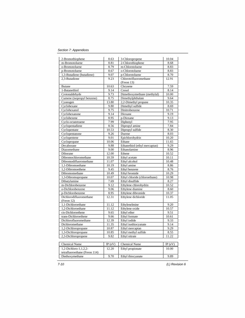
Section 7: Appendices
7-10 (L) Revision 6
2-Bromothiophene 8.63 3-Chloropropene 10.04m-Bromotoluene 8.81 2-Chlorothiophene 8.68o-Bromotoluene 8.79 m-Chlorotoluene 8.83p-Bromotoluene 8.67 o-Chlorotoluene 8.831,3-Butadiene (butadiene) 9.07 p-Chlorotoluene 8.702,3-Butadione 9.23 Chlorotrifluoromethane
(Freon 13)12.91
Butane 10.63 Chrysene 7.591-Butanethiol 9.14 Cresol 8.14Crotonaldehyde 9.73 Dimethoxymethane (methylal) 10.00Cumene (isopropyl benzene) 8.75 Dimethylphthalate 9.64Cyanogen 13.80 2,2-Dimethyl propane 10.35Cyclohexane 9.80 Dimethyl sulfide 8.69Cyclohexanol 9.75 Dinitrobenzene 10.71Cyclohexanone 9.14 Dioxane 9.19Cyclohexene 8.95 p-Dioxane 9.13Cyclo-octatetraene 7.99 Diphenyl 7.95Cyclopentadiene 8.56 Dipropyl amine 7.84Cyclopentane 10.53 Dipropyl sulfide 8.30Cyclopentanone 9.26 Durene 8.03Cyclopentene 9.01 Epichlorohydrin 10.20Cyclopropane 10.06 Ethane 11.65Decaborane 9.88 Ethanethiol (ethyl mercaptan) 9.29Diazomethane 9.00 Ethanolamine 8.96Diborane 12.00 Ethene 10.52Dibromochloromethane 10.59 Ethyl acetate 10.11Dibromodifluoromethane 11.07 Ethyl alcohol 10.481,1-Dibromoethane 10.19 Ethyl amine 8.861,2-Dibromoethene 9.45 Ethyl benzene 8.76Dibromomethane 10.49 Ethyl bromide 10.291,3-Dibromopropane 10.07 Ethyl chloride (chloroethane) 10.98Dibutylamine 7.69 Ethyl disulfide 8.27m-Dichlorobenzene 9.12 Ethylene chlorohydrin 10.52o-Dichlorobenzene 9.06 Ethylene diamine 8.60p-Dichlorobenzene 8.95 Ethylene dibromide 10.37Dichlorodifluoromethane(Freon 12)
12.31 Ethylene dichloride 11.05
1,1-Dichloroethane 11.12 Ethylenelmine 9.201,2-Dichloroethane 11.12 Ethylene oxide 10.57cis-Dichloroethene 9.65 Ethyl ether 9.51trans-Dichloroethene 9.66 Ethyl formate 10.61Dichlorofluoromethane 12.39 Ethyl iodide 9.33Dichloromethane 11.35 Ethyl isothiocyanate 9.141,2-Dichloropropane 10.87 Ethyl mercaptan 9.291,3-Dichloropropane 10.85 Ethyl methyl sulfide 8.552,3-Dichloropropene 9.82 Ethyl nitrate 11.22
Chemical Name IP (eV) Chemical Name IP (eV)
1,2-Dichloro-1,1,2,2-tetrafluoroethane (Freon 114)
12.20 Ethyl propionate 10.00
Diethoxymethane 9.70 Ethyl thiocyanate 9.89
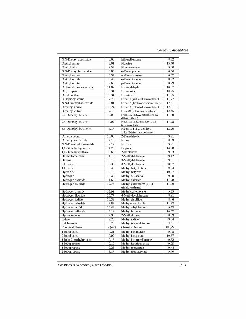
Section 7: Appendices
Passport PID II Monitor, User's Manual 7-11
N,N-Diethyl acetamide 8.60 Ethynylbenzene 8.82Diethyl amine 8.01 Fluorine 15.70Diethyl ether 9.53 Fluorobenzene 9.20N,N-Diethyl formamide 8.89 o-Fluorophenol 8.66Diethyl ketone 9.32 m-Fluorotoluene 8.92Diethyl sulfide 8.43 o-Fluorotoluene 8.92Diethyl sulfite 9.68 p-Fluorotoluene 8.79Difluorodibromomethane 11.07 Formaldehyde 10.87Dihydropyran 8.34 Formamide 10.25Diiodomethane 9.34 Formic acid 11.05Diisopropylamine 7.73 Freon 11 (trichlorofluoromethane) 11.77N,N-Dimethyl acetamide 8.81 Freon 12 (dichlorodifluoromethane) 12.31Dimethyl amine 8.24 Freon 13 (chlorotrifluoromethane) 12.91Dimethylaniline 7.13 Freon 22 (chlorofluoromethane) 12.452,2-Dimethyl butane 10.06 Freon 112 (1,1,2,2-tetrachloro-1,2-
difluoroethane)11.30
2,3-Dimethyl butane 10.02 Freon 113 (1,1,2-trichloro-1,2,2-trifluororethane)
11.78
3,3-Dimethyl butanone 9.17 Freon 114 (1,2-dichloro-1,1,2,2-tetrafluoroethane)
12.20
Dimethyl ether 10.00 2-Furaldehyde 9.21Dimethylformamide 9.18 Furan 8.89N,N-Dimethyl formamide 9.12 Furfural 9.211,1-Dimethylhydrazine 7.28 Heptane 10.081,1-Dimethoxyethane 9.65 2-Heptanone 9.33Hexachloroethane 11.10 2-Methyl-1-butene 9.12Hexane 10.18 3-Methyl-1-butene 9.512-Hexanone 9.35 3-Methyl-2-butene 8.671-Hexene 9.46 Methyl butyl ketone 9.34Hydrazine 8.10 Methyl butyrate 10.07Hydrogen 15.43 Methyl cellosolve 9.60Hydrogen bromide 11.62 Methyl chloride 11.28Hydrogen chloride 12.74 Methyl chloroform (1,1,1-
trichloroethane)11.00
Hydrogen cyanide 13.91 Methylcyclohexane 9.85Hydrogen fluoride 15.77 4-Methylcyclohexene 8.91Hydrogen iodide 10.38 Methyl disulfide 8.46Hydrogen selenide 9.88 Methylene chloride 11.32Hydrogen sulfide 10.46 Methyl ethyl ketone 9.53Hydrogen telluride 9.14 Methyl formate 10.82Hydroquinone 7.95 2-Methyl furan 8.39Iodine 9.28 Methyl iodide 9.54Iodobenzene 8.73 Methyl isobutyl ketone 9.30Chemical Name IP (eV) Chemical Name IP (eV)
1-Iodobutane 9.21 Methyl isobutyrate 9.982-Iodobutane 9.09 Methyl isocyanate 10.671-Iodo-2-methylpropane 9.18 Methyl isopropyl ketone 9.321-Iodopentane 9.19 Methyl isothiocyanate 9.251-Iodopropane 9.26 Methyl mercaptan 9.442-Iodopropane 9.17 Methyl methacrylate 9.70

Section 7: Appendices
7-12 (L) Revision 6
m-Iodotoluene 8.61 1-Methyl napthalene 7.96o-Iodotoluene 8.62 2-Methyl napthalene 7.96p-Iodotoluene 8.50 2-Methylpentane 10.12Isobutane 10.57 3-Methylpentane 10.08Isobutyl acetate 9.97 2-Methyl propene 9.23Isobutyl alcohol 10.12 Methyl propionate 10.15Isobutyl amine 8.70 Methyl propyl ketone 9.39Isobutyl formate 10.46 α-Methyl styrene 8.35Isobutyraldehyde 9.74 Methyl thiocyanate 10.07Isobutyric acid 10.02 Monomethyl aniline 7.32Isopentane 10.32 Monomethyl hydrazine 7.67Isophorone 9.07 Morpholine 8.20Isoprene 8.85 Naphthalene 8.12Isopropyl acetate 9.99 Nickel carbonyl 8.27Isopropyl alcohol 10.16 Nitric oxide, (NO) 9.25Isopropyl amine 8.72 Nitrobenzene 9.92Isopropyl benzene 8.69 p-Nitrochloro benzene 9.96Isopropyl ether 9.20 Nitroethane 10.88Isovaleraldehyde 9.71 Nitrogen 15.58Ketene 9.61 Nitrogen dioxide 9.782,3-Lutidine 8.85 Nitrogen trifluoride 12.972,4-Lutidine 8.85 Nitromethane 11.082,6-Lutidine 8.85 1-Nitropropane 10.88Maleic anhydride 10.80 2-Nitropropane 10.71Mesitylene 8.40 Nitrotoluene 9.45Mesityl oxide 9.08 Octane 9.82Methane 12.98 Oxygen 12.08Methanethiol (methylmercaptan)
9.44 Ozone 12.08
n-Methyl acetamide 8.90 Pentaborane 10.40Methyl acetate 10.27 Pentane 10.35Methyl acetylene 10.37 2,4-Pentanedione 8.87Methyl acrylate 9.90 2-Pentanone 9.38Methylal (dimethoxymethane) 10.00 1-Pentene 9.50Methyl alcohol 10.85 Perchloroethylene 9.32Methyl amine 8.97 Pheneloic 8.18Methyl-n-amyl ketone 9.30 Phenol 8.50Methyl bromide 10.54 Phenylene diamine 6.89Phenyl ether (diphenyl oxide) 8.82 Sulfuryl fluoride 13.00Phenyl hydrazine 7.64 o-Terphenyls 7.78
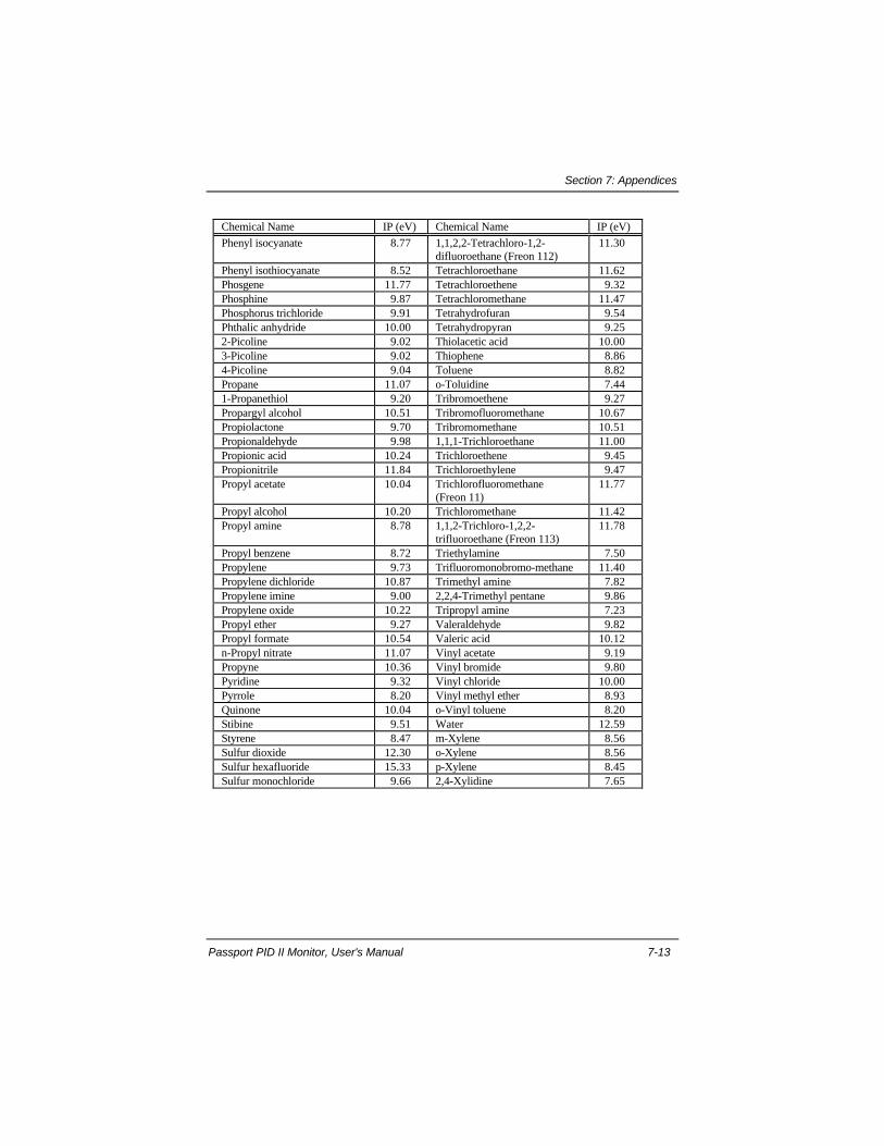
Section 7: Appendices
Passport PID II Monitor, User's Manual 7-13
Chemical Name IP (eV) Chemical Name IP (eV)
Phenyl isocyanate 8.77 1,1,2,2-Tetrachloro-1,2-difluoroethane (Freon 112)
11.30
Phenyl isothiocyanate 8.52 Tetrachloroethane 11.62Phosgene 11.77 Tetrachloroethene 9.32Phosphine 9.87 Tetrachloromethane 11.47Phosphorus trichloride 9.91 Tetrahydrofuran 9.54Phthalic anhydride 10.00 Tetrahydropyran 9.252-Picoline 9.02 Thiolacetic acid 10.003-Picoline 9.02 Thiophene 8.864-Picoline 9.04 Toluene 8.82Propane 11.07 o-Toluidine 7.441-Propanethiol 9.20 Tribromoethene 9.27Propargyl alcohol 10.51 Tribromofluoromethane 10.67Propiolactone 9.70 Tribromomethane 10.51Propionaldehyde 9.98 1,1,1-Trichloroethane 11.00Propionic acid 10.24 Trichloroethene 9.45Propionitrile 11.84 Trichloroethylene 9.47Propyl acetate 10.04 Trichlorofluoromethane
(Freon 11)11.77
Propyl alcohol 10.20 Trichloromethane 11.42Propyl amine 8.78 1,1,2-Trichloro-1,2,2-
trifluoroethane (Freon 113)11.78
Propyl benzene 8.72 Triethylamine 7.50Propylene 9.73 Trifluoromonobromo-methane 11.40Propylene dichloride 10.87 Trimethyl amine 7.82Propylene imine 9.00 2,2,4-Trimethyl pentane 9.86Propylene oxide 10.22 Tripropyl amine 7.23Propyl ether 9.27 Valeraldehyde 9.82Propyl formate 10.54 Valeric acid 10.12n-Propyl nitrate 11.07 Vinyl acetate 9.19Propyne 10.36 Vinyl bromide 9.80Pyridine 9.32 Vinyl chloride 10.00Pyrrole 8.20 Vinyl methyl ether 8.93Quinone 10.04 o-Vinyl toluene 8.20Stibine 9.51 Water 12.59Styrene 8.47 m-Xylene 8.56Sulfur dioxide 12.30 o-Xylene 8.56Sulfur hexafluoride 15.33 p-Xylene 8.45Sulfur monochloride 9.66 2,4-Xylidine 7.65

MSA and Passport are trademarks of Mine Safety AppliancesCompany.
© Mine Safety Appliances Company 2000All Rights Reserved.Printed in the United States of America