patellofemoral joints for tangential axial radiography of
TRANSCRIPT

Page 1/18
A Study on the Development and Application ofPatellofemoral Joint Radiography Auxiliary Devicefor Tangential Axial Radiography of the Patellar andPatellofemoral JointsDo-Byung Rhee
Catholic University of Daegu https://orcid.org/0000-0001-7474-9127Hee-June Kim
Kyungpook National University HospitalDeok-Mun Kwon
Daegu Health CollegeJung-Su Kim
Daegu Health CollegeHyun-Woo Choi
Kyungpook National University School of MedicineJong-Ki Kim ( [email protected] )
Catholic University of Daegu School of Medicine
Research Article
Keywords: patellar, patellofemoral joints, Settegast, Hughston, Laurin, Merchant
Posted Date: September 13th, 2021
DOI: https://doi.org/10.21203/rs.3.rs-869658/v1
License: This work is licensed under a Creative Commons Attribution 4.0 International License. Read Full License

Page 2/18
AbstractThis study evaluated the accuracy of tangential axial radiography of the patellofemoral joints using anauxiliary device, which we named patellofemoral joint radiography (PJR). To compare the PJR andconventional radiography methods such as the Laurin, Merchant, and Settegast, the images taken bythree methods were evaluated using a whole body phantom (PBU-31). Settegast was the radiographicmethod that had the smallest inclination of the patella and showed the best half lateral image of thepatella, with a difference of 5.76% when compared with PJR (p = 0.001). PJR was the method that had thelargest distance between the patellar and femoral joint spaces, with a difference of 14.54% whencompared with the Merchant method (p = 0.001). PJR was the method in which the two bones were welloverlapped (i.e., measured by the distance between the femoral trochlear groove and the tibial tuberosity),with a difference of 109.41% when compared with the Merchant method (p = 0.001). The Settegastmethod has the image with the smallest inclination of the patella, but the PJR has the image that bestdescribes the patellofemoral joint and the least distortion of the image. when using PJR, bending the kneeby 40° degree and setting a 140° angle between the long axis of the femur and the long axis of the lowerleg were considered to be the most bene�cial conditions. We propose the use of PJR for tangential axialradiography of the patellar and patellofemoral joints.
IntroductionIn general, knee pain is caused by an imbalance in the patellar tracking control during knee �exion andextension [1]. If the structures that cause the patella to travel past the femoral trochlear groove are not inbalance when the knee joint is extended, friction occurs on the patellar surface and prevents propermovement of the patella; in severe cases, this may cause dislocation. The stress generated by thisabnormal movement route causes pain in the patellofemoral joint [2]. Examinations of the patellofemoraljoint are diverse and include physical examination, radiography, CT, MRI, and arthroscopy. Among these,visual examination and radiography are the primary tests that are mainly performed to diagnoseproblems, such as patellar fracture, dislocation, and subluxation and knee joint varus, valgus, andmalalignment. There are several radiographic methods to assess various diseases of the patellofemoraljoint. Patellofemoral joint tangential axial radiography and intercondyloid fossa radiography are mainlyperformed [3, 4]. Tangential axial radiography is advantageous for evaluating wear on the patellofemoraljoint surface, identifying the half lateral image of the patella, and understanding the relationship betweenthe femur and tibia. Moreover, it is an important radiographic method for determining patellofemoral jointstructure, shape, and damage [5]. Existing radiography methods have caused distinct problems. TheSettegast and Hughston methods perform radiography in prone knee bending position. This methodcannot be used to patients with knee �exion contracture or patellar fractures and dislocations. The Laurinmethod performs radiography by bending the knee in a sitting position. since a patient must directly holdthe detector (image receptor) in a sitting position and perform radiographic imaging, there is a risk ofshaking and falling from an unstable position When performing radiographs by Merchant method, thelegs should be placed in the Merchant-speci�c auxiliary device in the supine position. Both knees shouldbe radiographed twice each, and the position of the femur should be kept horizontal on the examination

Page 3/18
table. Therefore, the authors of this study developed a patellofemoral joint radiography (PJR) auxiliarydevice (Fig. 1) to directly solve the problems encountered during conventional imaging. The biggestadvantage of the PJR method is that a patient can �ne-tune the angle of the knee after putting the leg intoan auxiliary device in the supine position. The purpose of this study was to compare the PJR method withconventional radiographic methods for tangential axial radiography of the patellofemoral joints. Inaddition, radiographic evaluation items were set and used to compare radiographic images anddetermine the most suitable among the radiographic methods.
Materials And Methods2.1. Experimental equipment
The X-ray imaging equipment used in this study was the Digital Radiography X-ray System (Innovision-SH3D; DK Healthcare Co.). For the wireless detector type, a mobile �at panel detector [FXRD-1417NAW model(CsI)] was used. The left leg, including the patellar and patellofemoral joints, of the whole body phantom(PBU-31, Kyoto Kahaku Inc., Japan) was used.
2.2. Experimental methods
Using PJR, the phantom knee was bent at 70° to 20° by varying the angle at 10° intervals, and the longaxes of the femur and lower leg were set at 110° to 160°. At this time, the angles of the X-ray tube anddetector were positioned to remain perpendicular to the angle of the patella with every change in duringknee bend at 10° (Figs. 2 and 3a). Each of the six radiography methods collected 30 images, and a totalof 180 images were compared and analyzed. The Houston method is advantageous for patients whocannot bend the knee less than 45° to 55°, but it has a large disadvantage of causing distortion in theradiographic image. Radiography in the prone position was performed only by the Settegast method, inwhich the X-ray tube was set at an angle of 15° toward the patella by bending the phantom's knee to 105°(Fig. 3b) [6–9]. 30 settegast images were collected. The Laurin method is a condition in which the knee isbent by 20° and the long axis of the femur and the long axis of the tibia and �bula are set at an angle of160° (Fig. 3c) [10, 11]. 30 Laurin images were collected. The Laurin method is contained within themethod using PJR. With the Merchant method, the knee was bent at 45°, each leg was placed in aMerchant-speci�c assist device, the detector was positioned about 30 cm below the knee, and the X-raytube was positioned at an angle of 30° toward the patella (Fig. 3d) [12]. 30 Merchant images werecollected. The following radiographic settings were the same for all methods: 55 kV, 250 mA, 0.045seconds of exposure time, and a source to image receptor distance (SID) of 110 cm (Fig. 4). Theradiographic evaluation items were:
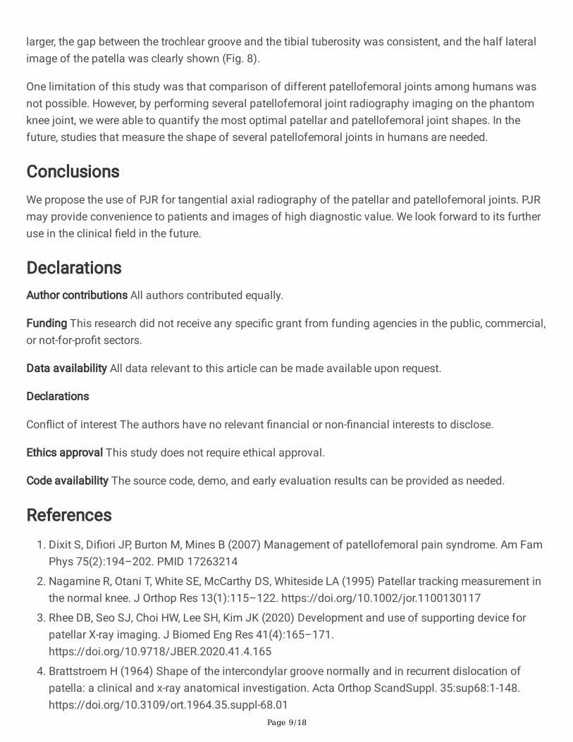
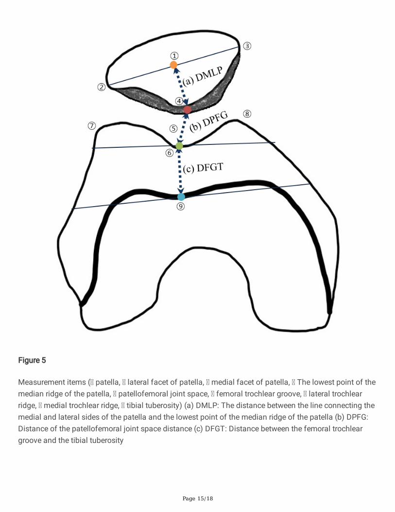
a) the distance between the line connecting the medial and lateral sides of the patella and the lowestpoint of the median ridge of the patella (DMLP), which was measured to evaluate patellar inclination. Thesmaller the DMLP measurement result, the better.
b) the patellofemoral joint space distance (DPFG). The larger the DPFG measurement result, the better.

Page 4/18
c) the distance between the femoral trochlear groove and the tibial tuberosity (DFGT), which wasmeasured to evaluate the degree of overlap between the two bones. As a result of DFGT measurement,values near the number 0 are superior (Fig. 5).
2.3. Statistical analysis
The quantitative values of the radiographic images were measured and evaluated using a PictureArchiving Communication System program (Centricity, GE healthcare, Chicago, IL, USA). For eachmeasured variable, statistical signi�cance was veri�ed by one-way ANOVA using the Statistical Packagefor the Social Sciences software (SPSS 20.0, IBM SPSS Statistics, Chicago, IL, USA). Using the PJR, thephantom's knee �exion was changed six times at 10° intervals to �nd the most appropriate radiographicconditions among the measured values, which were then compares with those by the Laurin, Merchant,and Settegast methods using one-way ANOVA. The statistical signi�cance level was set to p < 0.05.
Results3.1. Phantom experiment using the PJR
In all experiments, the X-ray tube angle and detector angle settings were made perpendicular to thepatellar angle. A summary of the measurement results are shown in Table 1 and Fig. 6a. The followingwere the �ndings with each change in the angle of the phantom's knee for six times at 10° intervals usingPJR: a) the smallest inclination of the patella based on DMLP evaluation was when the knee was bend ata 20° degree angle, the angle between the long axis of the femur and the lower leg was 160°; this was thesame method as the Laurin method; b) the largest patellofemoral joint spacing based on DPFGevaluation was when the knee was bend at a 40 degree, the angle between the long axis of the femur andthe lower leg was 140°; and c) the most consistent value for the distance between the femoral trochleargroove and the tibial tuberosity based on the DFGT evaluation was when the knee was bend at a 40degree, the angle between the long axis of the femur and the lower leg was 140°.

Page 5/18
Table 1Results of taking radiographic images at 160° to 110° by changing the knee �exion angle at 10° intervals
using Development of patellofemoral joint radiography auxiliary device (PJR)PJRused
Measure
Parameter 70° 60° 50° 40° 30° 20° p-value
Degree of�exion
Patellarangle
18° 15° 12° 9° 6° 4° -
X-ray tubeangle
108° 105° 102° 99° 96° 94° -
Detectorangle
72° 75° 78° 81° 84° 86° -
a) DMLP 11.27 ± 0.16
10.69 ± 0.23
10.24 ± 0.23
9.97 ± 0.15
9.95 ± 0.1
9.95 ± 0.1 0.001
b) DPFG 11.16 ± 0.71
11.59 ± 0.68
9.41 ± 0.36
12.35 ± 0.67
10.1 ± 0.53
8.28 ± 0.65 0.001
c) DFGT -4.14 ± 0.16
-5.47 ± 0.2
-5.75 ± 0.17
-0.37 ± 0.36
2.5 ± 0.32
4.87 ± 0.26 0.001
DMLP = The distance between the line connecting the medial and lateral sides of the patella and thelowest point of the median ridge of the patella, which was measured to evaluate patellar inclination
DPFG = The patellofemoral joint space distance
DFGT = The distance between the femoral trochlear groove and the tibial tuberosity, which wasmeasured to evaluate the degree of overlap between the two bones
The difference in the DMLP values between knee �exion by 20° degree, 160° angle of the long axis of thefemur and lower leg and knee �exion by 40° degree, 140° angle of the long axis of the femur and lowerleg was not signi�cantly different at 0.24% (p = 1.000). In the DPFG evaluation, the largest patellofemoraljoint spacing was when the knee was bent at 40° degree, the angle between the long axis of the femurand the lower leg was set to 140°. When the knee was bent at 20° degree, the angle between the long axisof the femur and the lower leg was 160°, the change in the DPFG value was not signi�cant at 32.94% (p = 1.000). In the DFGT evaluation, the most consistent value between the femoral trochlear groove and thetibial tuberosity was when the knee was bent at 40° degree, the angle between the long axis of the femurand the lower leg was set to 140°. When the knee was bent at 20° degree, the angle between the long axisof the femur and the lower leg was 160°, the change in the DFGT value was signi�cantly different at107.56% (p < 0.05) (Table 2).

Page 6/18
Table 2Comparison of PJR images taken at 140° and 160° of knee �exion anglesComparison between two groups Measure
Parameter 40° 20° p-value
Degree of �exion
Patellar angle 9° 4° -
X-ray tube angle 99° 94° -
Detector angle 81° 86° -
a) DMLP 9.97 ± 0.15 9.95 ± 0.1 1.000
b) DPFG 12.35 ± 0.68 8.28 ± 0.65 0.001
c) DFGT -0.37 ± 0.36 4.87 ± 0.22 0.001
3.2. Comparison of PJR with the Settegast and Merchant radiography methods
The measured values using PJR with the phantom's knee bent at 40° degree and the angle between thelong axis of the femur and the long axis of the lower leg set at 140° were compared with the valuesmeasured by the Settegast and Merchant methods. The results of comparisons of all measurements areshown in Table 3 and Fig. 6b.
Table 3Comparison of the measured values by PJR with those of the Merchant and Settegast
methodsComparison among three groups Measure
Parameter PJR
40°
Merchant
45°
Settegast
105°
p-value
Degree of �exion
Patellar angle 9° 13° 14.5° -
X-ray tube angle 99° 60° 15° -
Detector angle 81° 45° 0° -
a) DMLP 9.97 ± 0.15 10.57 ± 0.47 9.40 ± 0.47 0.001
b) DPFG 12.35 ± 0.68 10.55 ± 0.43 8.54 ± 0.65 0.001
c) DFGT -0.37 ± 0.36 3.93 ± 0.23 5.42 ± 0.49 0.001
In the DMLP evaluation, the smallest patellar inclination and best display of the half lateral image of thepatella was with the Settegast method, followed by PJR and the Merchant method. The measured DMLPvalues signi�cantly differed by 5.76% between the Settegast method and PJR; by 5.62% between PJR and

Page 7/18
the Merchant methods (p = 0.001). In the DPFG evaluation, the largest patellofemoral joint spacing wasseen with PJR, followed by the Merchant method and the Settegast method. The measured DPFG valuessigni�cantly differed by 14.54% between PJR and the Merchant method; by 19.01% between the Settegastand Merchant methods (p = 0.001). In the DFGT evaluation, the distance between the femoral trochleargroove and the tibial tuberosity was the most consistent with PJR, followed by the Merchant method andthe Settegast method. The measured DFGT values signi�cantly differed by 109.41% between PJR and theMerchant method; by 27.75% between the Settegast and Merchant methods (p = 0.001).
DiscussionThis study was conducted to �nd the most suitable tangential axial radiography method for the patellarand patellofemoral joints by comparing PJR with the conventional radiographic methods. Among theradiographic conditions using PJR weres compared with the conventional imaging methods of Settegastand Merchant. In the DMLP evaluation, when the knee of the phantom was bent at 70° to 20° at 10°intervals using PJR, the DMLP value decreased as the angle of �exion was increased. This implied thatthe inclination or tilt of the patella decreased when the knee was extended than when the knee was �exedand that the half lateral image of the patella was more accurately displayed with the former. Laurinmethod with a knee �exion angle of 20° had the smallest inclination of the patella and the half lateralimage of the patella showed the best results. But, based on the DFGT results, as the value representingthe distance between the femoral trochlear groove and the tibial tuberosity increased to a positive value,the tibial tuberosity invaded the patellofemoral joint area and resulted in narrowing of the patellofemoraljoint space. On the other hand, as the distance between the femoral trochlear groove and the tibialtuberosity was reduced to a negative value, the inclination of the patella became larger. In addition,among the radiographic conditions using PJR, 20° knee �exion, which is similar to that in the Laurinmethod, and 160° angle of the long axis of the femur to the long axis of the lower leg resulted in thelargest invasion of the tibial tuberosity to the patellofemoral joint and the narrowest patellofemoral jointspacing (Fig. 6a). Although the Settegast method gave the smallest inclination of the patella on imaging,it required the largest knee bending angle and may cause further discomfort to a patient with knee pain.When the distance between the femoral trochlear groove and the tibial tuberosity was the largest and thetibial surface invaded the patellofemoral joint space, the resulting image had the narrowest joint spacing.The reason for the result of the smallest inclination of the patella with the Settegast method than with theMerchant and PJR methods was thought to be close contact of the patella with the detector in the proneposition. The object to image receptor distance (OID) between the patella and the detector was the targetarea for radiographic imaging. If the OID was short, distortion in the radiographic image was reduced. Onthe other hand, if the OID was increased, the image was enlarged and had a degraded quality, resulting inblurring and low contrast [13–15]. The Merchant method showed the greatest patellar inclination, and theoverlap between the patellofemoral joint space and the femoral trochlear groove and the tibial tuberositywas not as good as the PJR method, but better than the Settegast method. With the results of the DMLP,DPFG, and DFGT evaluations taken together, 40° knee �exion with 140° angle between the long axis of
Page 8/18
the femur and the long axis of the lower leg was the most bene�cial radiographic condition using PJR(Fig. 6b).
Tangential axial radiography must be performed in order to detect patellar fracture and injury andpatellofemoral joint stenosis and wear and to determine the correlation between the femur and tibia.However, conventional radiography methods have several disadvantages. First, although the Settegastand Hughston methods are relatively frequent in the clinical setting because of the relatively shortprocedure time, the required prone position and knee �exion may be di�cult in patients complaining ofpain from patellar fracture or dislocation [3, 16–18]. In the prone position, the patellar area comes intocontact with the examination table and a load is applied; this may worsen the pain in the area near theknee and should be avoided [3, 17]. Second, the Laurin and Merchant methods are radiographic methodsthat can be used to diagnose patellofemoral joint disease in a sitting or supine position without the needto prone. The Laurin method mainly measures the lateral patellofemoral angle and checks whetherpatellar is normally open to the outside. The Laurin method was said to require the smallest bendingangle of the knee and was the closest to the actual structure of the patellar [10, 11]. However, as the kneebending angle decreases, the distance between the femoral trochlear groove and the tibial tuberosityincreases, the tibial surface invades the patellofemoral joint space, and the gap narrows. Therefore, this isnot suitable for viewing minute damages to the patellofemoral joint. Moreover, the Laurin methodnecessitates postural instability, because the patient must bend the knee in a sitting position, directly holdthe detector, and perform radiography. In addition, in a sitting position, special care is required to avoidradiation exposure of areas other than the patellofemoral joint [3].
Most of the existing studies on patellofemoral joint observation determined patellar dislocation andsubluxation by measuring the congruence and sulcus angles [15, 19, 20]. To measure this in the Merchantmethod, the long axis of the femur must be parallel to the surface of the examination table using anauxiliary device. In the Merchant method, each knee is radiographed separately. When both legs are shotsimultaneously, one leg may not be �xed and the knee may be adducted or abducted; these may increasethe matching angle and distort the image [19]. In addition, when the distance from the source is doubled,the radiation intensity is proportional to the inverse square of the distance, where the radiation level perunit area decreases to 1/4 [22]. In the case of similar source to image receptor distance (SID), as thedistance from the source of the X-ray tube to the object part (SOD) increases, the entrance surface dosedecreases. Conversely, as the OID becomes closer, enlargement of the image is prevented [13, 23]. The setOID was about 30 cm for the Merchant method and about 20 cm for PJR (Fig. 7). In this research,because the tangential axial radiography method using PJR had 10-cm longer SOD and 10-cm shorterOID, compared with those by the Merchant method, the latter will create more exposure to radiation doses.Comparison of radiation doses in tangential axial radiography of the patellofemoral joint requires morein-depth experiments. Nevertheless, radiographic imaging using PJR may be a good means of solvingsome of the shortcomings of the conventional radiographic methods. Speci�cally, PJR may allowpatients to comfortably undergo radiographic imaging in a supine position and may enable a stableposition to prevent shaking or distortion of the image at the target site. Compared with the conventionalradiographic methods, PJR showed radiographic images in which the patellofemoral joint space was
Page 9/18
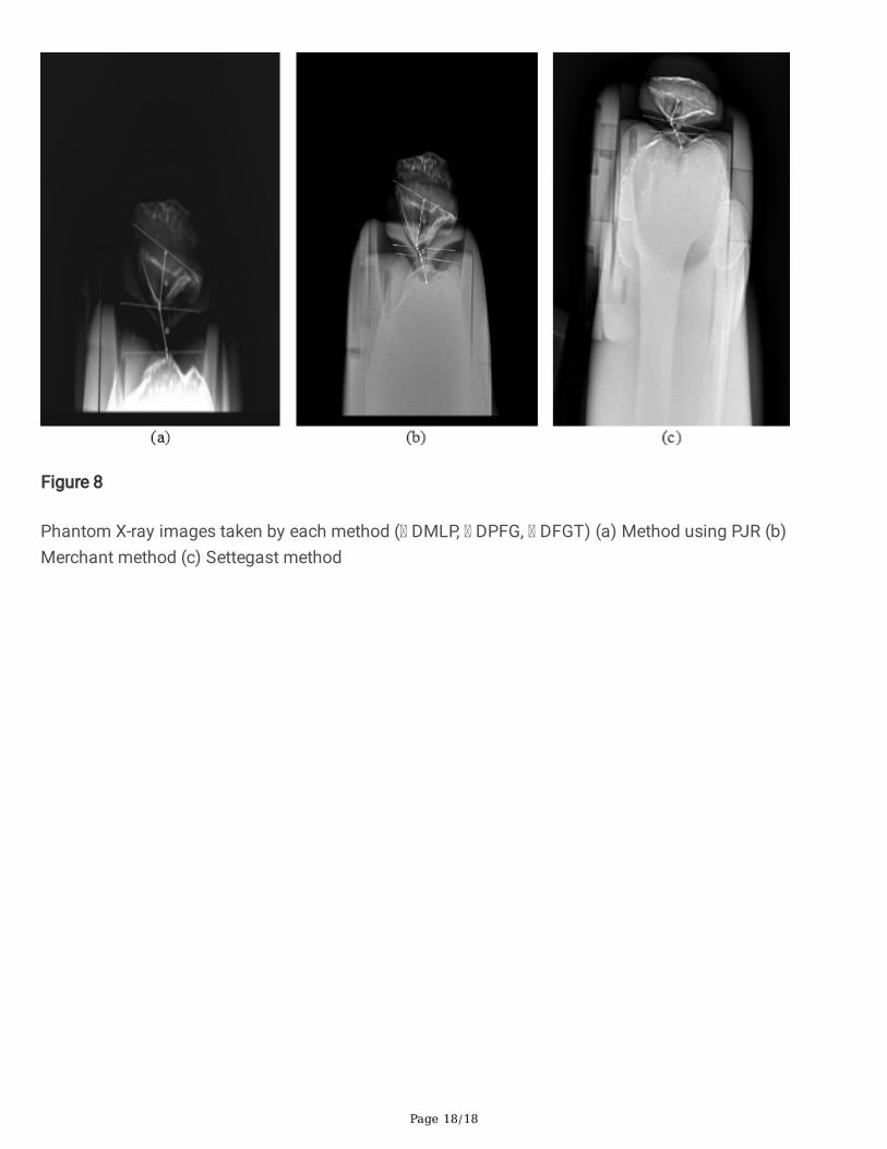
larger, the gap between the trochlear groove and the tibial tuberosity was consistent, and the half lateralimage of the patella was clearly shown (Fig. 8).
One limitation of this study was that comparison of different patellofemoral joints among humans wasnot possible. However, by performing several patellofemoral joint radiography imaging on the phantomknee joint, we were able to quantify the most optimal patellar and patellofemoral joint shapes. In thefuture, studies that measure the shape of several patellofemoral joints in humans are needed.
ConclusionsWe propose the use of PJR for tangential axial radiography of the patellar and patellofemoral joints. PJRmay provide convenience to patients and images of high diagnostic value. We look forward to its furtheruse in the clinical �eld in the future.
DeclarationsAuthor contributions All authors contributed equally.
Funding This research did not receive any speci�c grant from funding agencies in the public, commercial,or not-for-pro�t sectors.
Data availability All data relevant to this article can be made available upon request.
Declarations
Con�ict of interest The authors have no relevant �nancial or non-�nancial interests to disclose.
Ethics approval This study does not require ethical approval.
Code availability The source code, demo, and early evaluation results can be provided as needed.
References1. Dixit S, Di�ori JP, Burton M, Mines B (2007) Management of patellofemoral pain syndrome. Am Fam
Phys 75(2):194–202. PMID 17263214
2. Nagamine R, Otani T, White SE, McCarthy DS, Whiteside LA (1995) Patellar tracking measurement inthe normal knee. J Orthop Res 13(1):115–122. https://doi.org/10.1002/jor.1100130117
3. Rhee DB, Seo SJ, Choi HW, Lee SH, Kim JK (2020) Development and use of supporting device forpatellar X-ray imaging. J Biomed Eng Res 41(4):165–171.https://doi.org/10.9718/JBER.2020.41.4.165
4. Brattstroem H (1964) Shape of the intercondylar groove normally and in recurrent dislocation ofpatella: a clinical and x-ray anatomical investigation. Acta Orthop ScandSuppl. 35:sup68:1-148.https://doi.org/10.3109/ort.1964.35.suppl-68.01

Page 10/18
5. McAlindon TE, Cooper C, Kirwan JR, Dieppe PA (1993) Determinants of disability in osteoarthritis ofthe knee. Ann Rheum Dis 52(4):258–262. https://doi.org/10.1136/ard.52.4.258
�. Hobbs DL (2005) Tangential projection of the patella. Radiol Technol 77(1):20–21. PMID 16218017
7. Ficat RP, Philippe J, Hungerford DS (1979) Chondromalacia patellae: a system of classi�cation. ClinOrthop Relat Res 144(144):55–62. https://doi.org/10.1097/00003086-197910000-00011
�. Davies AP, Bayer J, Owen-Johnson S, Shepstone L, Darrah C, GlasgowM M, Donell ST (2004) TheOptimum Knee Flexion Angle for Skyline Radiography Is Thirty Degrees. Clin Orthop Relat Res423:166–171. https://doi.org/10.1097/01.blo.0000129160.07965.e7
9. Ko YW, Joo YC, Kim MS, Go YR (2020) The assessment of tube incidence angle for minimizing thepatellofemoral joint overlap distance in merchant View. J Radiol Sci Technol 43(3):161–167.https://doi.org/10.17946/JRST.2020.43.3.161
10. Laurin CA, Dussault R, Levesque HP (1979) The tangential x-ray investigation of the patellofemoraljoint: x-ray technique, diagnostic criteria and their interpretation. Clin Orthop Relat Res 144(144):16–26. https://doi.org/10.1097/00003086-197910000-00004
11. Laurin CA, Lévesque HP, Dussault R, Labelle H, Peides JP (1978) The abnormal lateral patellofemoralangle: a diagnostic roentgenographic sign of recurrent patellar subluxation. J Bone Joint Surg Am60(1):55–60. https://doi.org/10.2106/00004623-197860010-00007
12. Merchant AC, Mercer RL, Jacobsen RH, Cool CR (1974) Roentgenographic analysis of patellofemoralcongruence. J Bone Joint Surg Am 56(7):1391–1396. https://doi.org/10.2106/00004623-197456070-00007
13. Holliday M, Steward A (2021) Pre-operative templating for total hip arthroplasty: how doesradiographic technique and calibration marker placement affect image magni�cation. J Med RadiatSci 15. https://doi.org/10.1002/jmrs.461
14. Schueler BA (2000) The AAPM/RSNA physics tutorial for residents: general overview of �uoroscopicimaging. RadioGraphics 20(4):1115–1126. https://doi.org/10.1148/radiographics.20.4.g00jl301115
15. Pittayapat P, Thevissen P, Fieuws S, Jacobs R, Willems G (2010) Forensic oral imaging quality ofhand-held dental X-ray devices: comparison of two image receptors and two devices. Forensic Sci Int194(1–3):20–27. https://doi.org/10.1016/j.forsciint.2009.09.024
1�. Hughston JC (1968) Subluxation of the patella. J Bone Joint Surg Am 50(5):1003–1026.https://doi.org/10.2106/00004623-196850050-00014
17. Seoung YH (2013) Usefulness evaluation of merchant auxiliary equipment of body type changingsuitable for X-ray table integral type. J Korea Acad-Ind Coop Soc 14(6):2773–2779.https://doi.org/10.5762/KAIS.2013.14.6.2773
1�. Fulkerson JP (2002) Diagnosis and treatment of patients with patellofemoral pain. Am J Sports Med30(3):447–456. https://doi.org/10.1177/03635465020300032501
19. Chung YK, Lee KB, Young WK (1986) A clinical study of traumatic dislocation of the knee joint:analysis of 7 cases. J Korean Orthop Assoc 21(4):703–708.https://doi.org/10.4055/jkoa.1986.21.4.703

Page 11/18
20. Kim HJ, Joo YC, Choi JH, Lim WT (2019) Assessment of Congruence Angle according to the CentralX-ray in the Merchant View of patellofemoral Joint. J Radiol Sci Technol 42(6):423–428.https://doi.org/10.17946/JRST.2019.42.6.423
21. Aglietti P, Insall JN, Cerulli G (1983) Patellar pain and incongruence. I: Measurements ofincongruence. Clin Orthop Relat Res 176:217–224. PMID 6851329
22. Hoskins JK, Newman RD, Spero R, Schultz J (1985) Experimental tests of the gravitational inverse-square law for mass separations from 2 to 105 cm. Phys Rev D Part Fields 32(12):3084–3095.https://doi.org/10.1103/physrevd.32.3084
23. Sharma R, Sharma SD, Pawar S, Chaubey A, Kantharia S, Babu DA (2015) Radiation dose to patientsfrom X-ray radiographic examinations using computed radiography imaging system. J Med Phys40(1):29–37. https://doi.org/10.4103/0971-6203.152244
Figures
Figure 1
Development of patellofemoral joint radiography auxiliary device (PJR) (a) Structure of the PJR (b) Theform of widening the angle of the PJR (c) The form of narrowing the angle of the PJR

Page 12/18
Figure 2
Set the X-ray tube and detector angles to be perpendicular to the angle of the patella

Page 13/18
Figure 3
Patellar tangential axial radiography imaging (a) Patellar tangential axial projection method using thePJR (b) Settegast method (c) Laurin method (d) Merchant method
Page 14/18
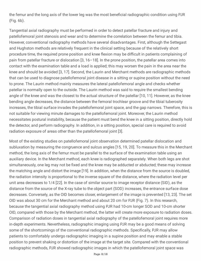
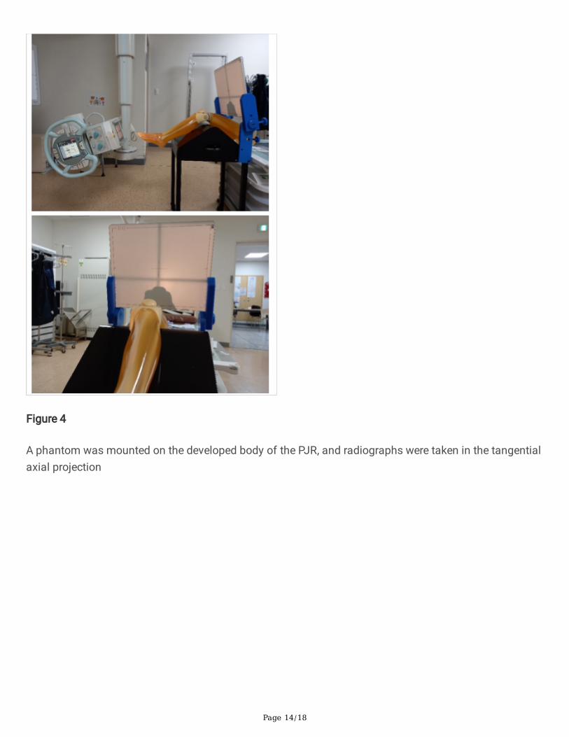
Figure 4
A phantom was mounted on the developed body of the PJR, and radiographs were taken in the tangentialaxial projection
Page 15/18
Figure 5
Measurement items ( patella, lateral facet of patella, medial facet of patella, The lowest point of themedian ridge of the patella, patellofemoral joint space, femoral trochlear groove, lateral trochlearridge, medial trochlear ridge, tibial tuberosity) (a) DMLP: The distance between the line connecting themedial and lateral sides of the patella and the lowest point of the median ridge of the patella (b) DPFG:Distance of the patellofemoral joint space distance (c) DFGT: Distance between the femoral trochleargroove and the tibial tuberosity

Page 16/18
Figure 6
(a) Results of taking radiographic images at 160° to 110° using PJR and changing the knee �exion angleat 10°, (b) A graph comparing the measurement results among PJR, Merchant method, and Settegastmethod

Page 17/18
Figure 7
Fundamental concepts of source to image receptor distance (SID), source to object distance (SOD) andobject to image receptor distance (OID)
Page 18/18
Figure 8
Phantom X-ray images taken by each method ( DMLP, DPFG, DFGT) (a) Method using PJR (b)Merchant method (c) Settegast method