path planning of mobile agents using ai … · cooperation and coordination among the robots. ......
TRANSCRIPT

PATH PLANNING OF MOBILE AGENTS USING AI TECHNIQUE
A THESIS SUBMITTED IN PARTIAL FULFILLMENT
OF THE REQUIREMENTS FOR THE DEGREE OF
Bachelor of Technology In
Mechanical Engineering
By
SOUMYA RANJAN SAHOO &
SAYAN ROY
Department of Mechanical Engineering National Institute of Technology
Rourkela 2007

PATH PLANNING OF MOBILE AGENTS USING AI TECHNIQUE
A THESIS SUBMITTED IN PARTIAL FULFILLMENT
OF THE REQUIREMENTS FOR THE DEGREE OF
Bachelor of Technology In
Mechanical Engineering
By
SOUMYA RANJAN SAHOO &
SAYAN ROY
Under the Guidance of
DR. D.R.K PARHI
Department of Mechanical Engineering National Institute of Technology
Rourkela 2007

National Institute of Technology
Rourkela
CERTIFICATE
This is to certify that the thesis entitled, “Path Planning of Mobile Agents Using AI
Techniques” submitted by Sri Soumya Ranjan Sahoo and Sri Sayan Roy in partial fulfillment
of the requirements for the award of Bachelor of Technology Degree in Mechanical
Engineering at the National Institute of Technology, Rourkela (Deemed University) is an
authentic work carried out by him under my supervision and guidance.
To the best of my knowledge, the matter embodied in the thesis has not been
submitted to any other University / Institute for the award of any Degree or Diploma.
Date: Dr. D.R.K Parhi
Dept. of Mechanical Engineering
National Institute of Technology
Rourkela - 769008
i
National Institute of Technology Rourkela
ACKNOWLEDGEMENT
I would like to articulate my deep gratitude to my project guide Dr. D.R.K Parhi who
has always been my motivation for carrying out the project.
It is my pleasure to refer Microsoft word 2003 of which the compilation of this report
would have been impossible.
An assemblage of this nature could never have been attempted without reference to
and inspiration from the works of others whose details are mentioned in reference section. I
acknowledge my indebtedness to all of them.
Last but not the least to all of my friends who were patiently extended all sorts of help
for accomplishing this undertaking.
Date: Soumya Ranjan Sahoo
Sayan Roy
Dept. of Mechanical Engineering
National Institute of Technology
Rourkela - 769008
ii

CONTENTS
Sl. No. Topic Page 1 Certificate i 2 Acknowledgement ii 3 Contents iii 4 Abstract iv 5 List of figures v 7 Chapter 1 : Introduction
Objective Root and strategy Webots
1 1-3 4
8 Chapter 2 : Literature survey 5-20 9 Chapter 3 : WORK ANALYSIS
My first bot Environment Robot A simple controller Summary
21 21-25 25-35 35-37 37
10 Chapter 4 :RESULTS AND DISCUSSION A simple controller Output Conclusion
39 40-42 42 43
11 Chapter 5 : Conclusion
44-45
12 Appendix : Program for simple controller Summary
46 47
13 Reference 48-51
iii

Abstract
In this paper, we study coordinated motion in a swarm robotic system, called
a swarm-bot. A swarm-bot is a self-assembling and self-organizing. Artifact composed of a
swarm of s-bots, mobile robots with the ability to connect to and isconnect from each other.
The swarm-bot concept is particularly suited for tasks that require all-terrain navigation
abilities, such as space exploration or rescue in collapsed buildings. As a first step toward the
development of more complex control strategies, we investigate the case in which a swarm-
bot has to explore an arena while avoiding falling into holes.
In such a scenario, individual s-bots have sensory–motor limitations that
prevent them navigating efficiently. These limitations can be overcome if the s-bots are made
to cooperate. In particular, we exploit the s-bots’ ability to physically connect to each other.
In order to synthesize the s-bots’ controller, we rely on artificial evolution, which we show to
be a powerful tool for the production of simple and effective solutions to the hole avoidance
task.
iv
Chapter 1 INTRODUCTION Objective Root and strategy
INTRODUCTION
We describe the s-bot , small autonomous robot with self assembly capabilities in
which a group of s-bots perform a variety of tasks which require self assembling ,physical
cooperation and coordination among the robots.
Objective:
The main scientific objective of the project is the study of the novel ways of
designing self organizing and self –assembling artifacts, based on swarm robotics technique.
ROOTS and STRATEGY:
Swarm robotics is an emergent field of collective robotics that studies robotics
system composed of swarm of robots tightly interacting and cooperating to reach their goal, it
finds its roots in recent studies in animal societies such as ants and bees.
Social insects are a valuable source of inspiration for designing collectively
intelligent systems comprised of number of agents. Despite noise in the environment, errors
in the processing information and performing tasks and lack of global information, social
insects achieve their goals successfully. The design and realization of both the hardware and
the software of such a robotic system represents the scientific challenge of the SWARM-
BOTS project. In social insect colonies, even though individual members of the colony
dispose of limited cognitive and acting abilities, the swarm as a whole is able to collectively
solve complex problems such as nest building, defense, cleaning, brood care or foraging. The
complex collective behavior that emerges from simple interactions among individuals, and
between
1

individuals and the environment is referred to as swarm intelligence. The swarm robotics
approach is characterized by the application of swarm intelligence techniques to the control
of groups of robots, emphasizing principles such as decentralization, local interactions among
agents, indirect communication and the use of local information.
In real ant colonies the problem of exploration and navigation is solved by establishing paths.
This is done in a very simple and distributed manner. Ants lay trails of pheromone, a
chemical substance that attracts other ants. Deneubourg et al. showed that the process of
laying a pheromone trail is a food strategy for finding the shortest path between a nest and a
food source, thereby establishing a path that others can follow.
Swarm intelligence methods are for solving exploration and navigation tasks
performed by a swarm of robots in unknown environments. Our approach consists in using
chains of visually connected robots that collectively explore their environment. We adopt the
idea of robotic chains from Goss et al. [5], and realize our system stressing the swarm
intelligence approach. We conducted a series of experiments in simulation and put the
emphasis on evaluating the dynamics of the chain formation process. In particular, we
analyze several aspects of the quality of the chains, such as the shape of the formed chains or
the speed of the chain formation process, when varying robot group sizes and the values of
control parameters. The results show that our simple control system can be easily tuned to
obtain different behaviors at the group level.
Inspired by this methodology of path establishment by pheromone laying, our
approach to exploration is to use a chain of robots, where the robots themselves act as trail
markers, or beacons, in place of pheromone trails. We define a robotic chain to be a sequence
of robots, where two neighboring robots can sense each other and the distance between them
never exceeds a certain maximum sensing range. In our case, the robots can visually sense
each other by means
2

of an omni-directional camera. The range of this camera determines the maximum distance
between two neighboring robots. There are at least two advantages in using chains.
First, Robots can form a chain by following simple rules. Second, a robotic chain can
establish connections between different locations, enabling all other robots to get to one of
them by navigating along the chain. The distance between such locations can be bigger than
the perceptual range of one robot. Thus, the group of robots aggregated into a chain cans
collectively find solutions that overcome the limitations of a single robot.
Our work is carried out within the scope of the SWARM-BOTS project, 1 which aims at
developing a new robotic system, called a swarm-bot [3, 8]. A swarm-bot is defined as an
artifact composed of a swarm of s-bots, mobile robots with the ability to connect
to/disconnect from each other. Connections can be established if one s-bot grips another one,
and are advantageous for a variety of tasks such as stable navigation on rough terrain, passing
over a hole bigger than one s-bot, or retrieval of an object which is too big for a single s-bot.
As the real s-bots are not available for experimentation yet, we conducted all our experiments
in simulation. We use a sophisticated 3D simulation that takes into account the dynamics and
the collisions of rigid bodies. The behavior of the simulated s-bot has been compared with the
one of the two available real s-bot prototypes, revealing a close matching between them.
Therefore, we believe that the future validation of our work on the real s-bots will give good
results.
One of the most critical aspects of this project is clearly the connection between the
robots, which is also the core of the innovation. The problem of interconnecting robot
modules has already been addressed by many researchers in the field of self-reconfigurable
robots, leading to many design solutions. For example the MTRAN and the Poly- Bot
modular robots display some of the most interesting results and use efficient connection
solutions.
A peculiar feature of the Swarm-bot is that s-bots can exploit rich Connection
devices to self-assemble into various configurations, help each other, perform collective
transportation, and even communicate to each other. This feature, which is exploited
3
by several social insects [1], provides an additional dimension to collective robotics where
interactions among robots are often virtual or take place through pushing actions.
WEBOTS:
We did the simulation with help of Webots version 5.5.11 which a 3D mobile
robot simulator is allowing the users to simulate different types of mobile robots, including
wheeled robots, legged robots and flying robots.
Webots is professional mobile robot simulation software. It contains a rapid prototyping tool
allowing the user to create 3D virtual worlds with physics properties, such as mass
repartition, joints, friction coefficients, etc. The user can add simple inert objects or active
objects called mobile robots. Users can create complex virtual worlds and simulate their
robots within these environments. A complete programming library is provided to allow users
to program the robots (usually using the C, C++ or Java languages). From the controller
programs, it is possible to read sensor values and send motor commands to robots. Resulting
robot controllers can be transferred to real robots (Khepera robot with C controllers,
Hemisson robot with BotStudio controllers, Aibo, LEGO Mindstorms, etc.).
Webots is well suited for research and education projects related to mobile robotics. Many
mobile robotics projects have been relying on Webots for years in the following areas:
• Mobile robot prototyping (academic research, automotive industry, aeronautics,
vacuum cleaner industry, toy industry, lobbyism, etc.)
• Multi-agent research (swarm intelligence, collaborative mobile robots groups, etc.)
• Adaptive behavior research (Genetic evolution, neural networks, adaptive learning, AI,
etc.).
• Mobile robotics teaching (robotics lectures, C/C++/Java programming lectures,
robotics contest, etc.)
4

Chapter 2 Literature Survey Abstracts

LITERATURE SURVEY
Chain Formation in a Swarm of Robots Shervin Nouyan and Marco Dorigo I IRIDIA, Universit¶e Libre de Bruxelles, Brussels, Belgium
fvtrianni,etuci,[email protected]
March 2004
Abstract
In this paper, we present our first steps towards applying swarm intelligence methods for
solving exploration and navigation tasks performed by a swarm of robots in unknown
environments. Our approach consists in using chains of visually connected robots that
collectively explore their environment. We adopt the idea of robotic chains from Goss et al.
[5], and realize our system stressing the swarm intelligence approach.
We conducted a series of experiments in simulation and put the emphasis on evaluating the
dynamic of the chain formation process. In particular, we analyze several aspects of the
quality of the chains, such as the shape of the formed chains or the speed of the chain
formation process, when varying robot group sizes and the values of control parameters. The
results show that our simple control system can be easily tuned to obtain different behaviors
at the group level.
Swarm robotics is an emerging ¯eld within collective robotics [9] and is largely inspired by
studies of social insect behaviour. In swarm robotics, large groups of simple robots are used
to collectively solve problems that exceed the capabilities of a single robot. In social insect
colonies, even though individual members of the colony dispose of limited cognitive and
acting abilities, the swarm as a whole is able to collectively solve complex problems such as
nest building, defense, cleaning, brood care or foraging. The complex collective behaviour
that emerges from simple interactions among individuals, and between individuals and the
environment is referred to as swarm intelligence [1].
5
The swarm robotics approach is characterized by the application of swarm intelligence
techniques to the control of groups of robots, emphasizing principles such as decentralization,
local interactions among agents, indirect communication and the use of local information. We
are in general interested in applying swarm intelligence methods to the solution of
exploration and navigation tasks performed by a group of robots in unknown environments.
Instead of using a complex controller that enables a robot to expore its environment by, for
instance, building an internal map-like representation [4, 7], we aim at developing simple
control strategies for an individual robot leading to efficient solutions in the swarm of robots.
6
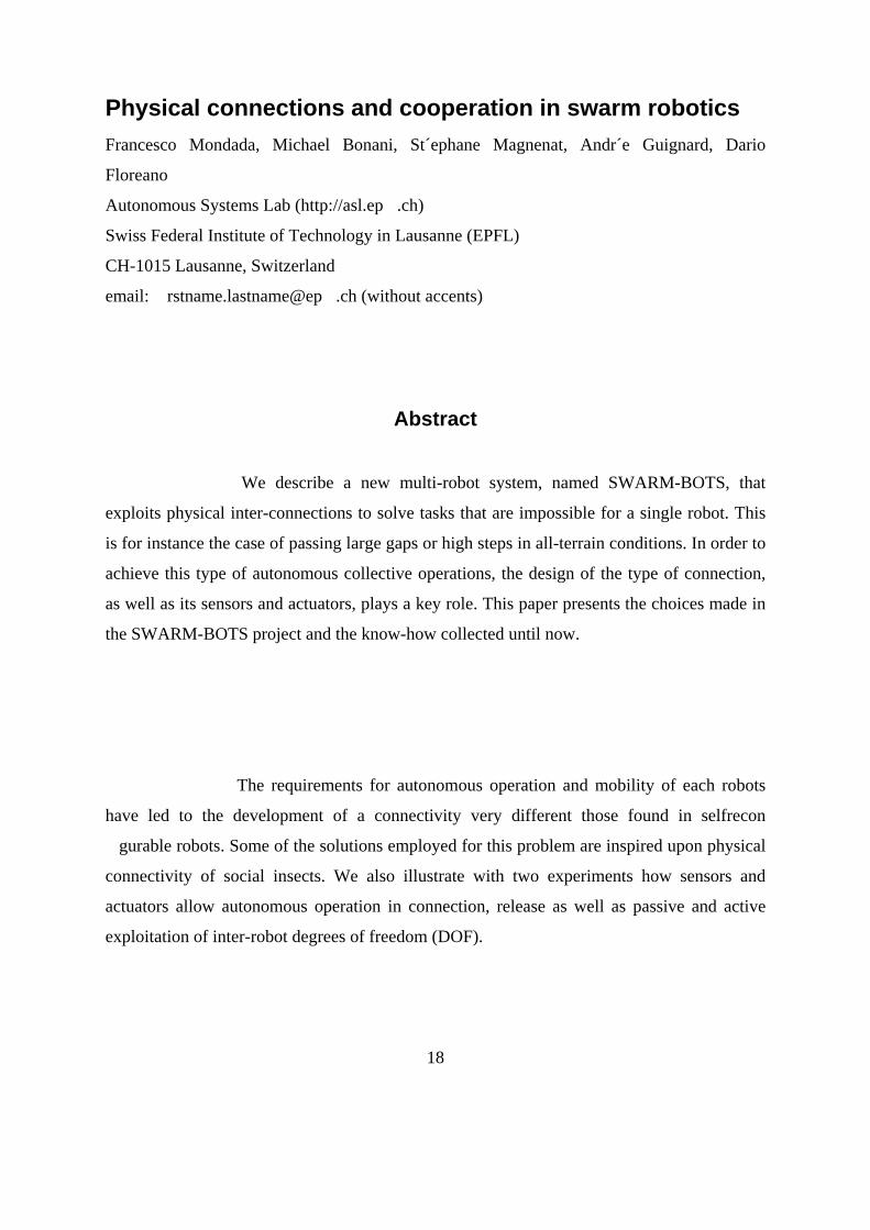
Physical connections and cooperation in swarm robotics Francesco Mondada, Michael Bonani, St´ephane Magnenat, Andr´e Guignard,
Dario Floreano
Autonomous Systems Lab (http://asl.ep_.ch)
Swiss Federal Institute of Technology in Lausanne (EPFL)
CH-1015 Lausanne, Switzerland
email: _rstname.lastname@ep_.ch (without accents)
Abstract. We describe a new multi-robot system, named SWARM-BOTS, that exploits physical inter-
connections to solve tasks that are impossible for a single robot. This is for instance the case
of passing large gaps or high steps in all-terrain conditions. In order to achieve this type of
autonomous collective operations, the design of the type of connection, as well as its sensors
and actuators, plays a key role.
This paper presents the choices made in the SWARM-BOTS project and the know-how
collected until now. The requirements for autonomous operation and mobility of each robots
have led to the development of a connectivity very different those found in selfreconfigurable
robots. Some of the solutions employed for this problem are inspired upon physical
connectivity of social insects. We also illustrate with two experiments how sensors and
actuators allow autonomous operation in connection, release as well as passive and active
exploitation of inter-robot degrees of freedom (DOF).
The goal of the SWARM-BOTS1 project is to explore new hardware and software aspects of
swarm intelligence [2]. A swarm-bot is composed of several small mobile robots (with a
diameter of 10 cm), called s-bots, able to autonomously self-assemble into bigger entities,
called swarm-bots [7, 6]. A peculiar feature of the Swarm-bot is that s-bots can exploit rich
connection devices to self-assemble into various configurations, help each other, perform
collective transportation, and even communicate to each other.
7
This feature, which is exploited by several social insects [1], provides an additional
dimension to collective robotics where interactions among robots are often virtual or take
place through pushing actions. One of the most critical aspects of this project is clearly the
connection between the robots, which is also the core of the innovation. The problem of
interconnecting robot modules has already been addressed by many researchers in the field of
self-reconfigurable robots, leading to many design solutions . For example the MTRAN and
the Poly- Bot modular robots display some of the most interesting results and use efficient
connection solutions. The MTRAN design [4] is based on permanent magnets for connection
and on shape memory alloy coils combined with non-linear springs for disconnection.
In the SWARM-BOTS project we have considered mechanical robustness in the context of
an autonomous connection. This has resulted in the choice of a system based on 2D shape
matching without penetration. This makes the connection less mechanically rigid, but
simplifies the connection procedure providing large tolerance to positioning and alignment.
This solution, which looks like a gripper, is also similar to the mechanisms used by animals
for this type of tasks, such as mandibles in ants or bees.
8

Evolving Functional Self-Assembling in a Swarm of
autonomous Robots Vito Trianni, Elio Tuci and Marco Dorigo
Abstract
The goal of this study is the design of controllers for robots capable of physically connecting
to each other, any time environmental contingencies prevent a single robot to achieve its goal.
This phenomenon is referred to as functional self-assembling. Despite its relevance as an
adaptie response, functional self-assembling has been rarely investigated within the context
of collective robotics.
Our task requires the robots to navigate within a rectangular corridor in
order to approach light bulbs positioned on the opposite end of the corridor with respect to
their starting positions. Aggregation and assembling are required in order to traverse a low
temperature area, within which assembled robots navigate more e_ectively than a group of
disconnected agents. The results of our empirical work demonstrate that controllers for a
group of homogeneous robots capable of functional self-assembling can be successfully
designed by using arti_cial neural networks shaped by evolutionary algorithms.
9

Cooperative Transport of Objects of Different Shapes and Sizes
Roderich Groß and Marco Dorigo IRIDIA - Universit´e Libre de Bruxelles - Brussels, Belgium
{rgross,mdorigo}@ulb.ac.be
Abstract .
This paper addresses the design of control policies for groups’ f up to 16 simple
autonomous mobile robots (called s-bots) for the cooperative transport of heavy objects of
different shapes and sizes. The -bots are capable of establishing physical connections with
each other end with the object (called prey).
We want the s-bots to self-assemble Into structures which pull or push the prey
towards a target location the s-bots are controlled by neural networks that are shaped by
artificial evolution. The evolved controllers perform quite well, independently of he shape
and size of the prey, and allow the group to transport the prey towards a moving target.
Additionally, the controllers evolved for a relatively small group can be applied to larger
groups, making possible the transport heavier prey. Experiments are carried out using a
physics simulator, which provides a realistic simulation of real robots, which are currently
under construction.
In the literature, several works can be found that consider the transport of an object
by a team of robots. Deneubourg et al. (1990) proposed the use of self-organized approaches
for the collection and transport of objects by robots in unpredictable environments. Each
robot unit could be simple and inefficient in itself, but a group of robots could exhibit
complex and efficient behaviors.Cooperation could be achieved without any direct
communication among robots (Grass´e, 1959; Deneubourg and Goss, 1989). Kube and Zhang
(1993a,b) studied a distributed approach to let a group of simple robots find and push a prey
towards a light.
10

Kube and Bonabeau (2000), on a follow-up of Kube and Zhang’s research, evaluated the
sensitivity of their robotic system to the prey’s geometry by comparing the performance on
prey of different shapes. They report that when the prey was a small cuboid, “as the number
of robots increased the task took longer to complete as the robot interference was high since
the limited box side space created competition.
In this paper, we aim at a robotic system that is appropriate for the
transport of prey of different shapes and sizes. We consider prey of cuboid as well as
cylindrical shape, with footprints that may differ in size by factors up to 6.25. In addition, the
prey can be of two different heights. The weight of the prey is independent of its geometry
and may vary up to a factor of 2.
11

Evolving Self-Organizing Behaviors for a Swarm-bot Marco Dorigo, Vito Trianni, Erol S�ahin, Roderich Gro�,
Thomas H. Labella, Gianluca Baldassarre, Stefano Nol,
Jean-Louis Deneubourg, Francesco Mondada,
Dario Floreano, Luca M. Gambardella
Technical Report No.
TR/IRIDIA/2003-11 June 2004
IRIDIA - Universit_e Libre de Bruxelles, Belgium
_KOVAN - Department of Computer Engineering,
Middle East Technical University, Ankara, Turkey
xInstitute of Cognitive Sciences and Technologies - CNR, Roma, Italy
zCENOLI - Universit_e Libre de Bruxelles, Belgium
?ASL - Swiss Federal Institute of Technology, Lausanne, Switzerland
#IDSIA, Manno-Lugano, Switzerland
Abstract In this paper, we introduce a self-assembling and self-organizing artifact,
called a swarm- bot, composed of a swarm of s-bots, mobile robots with the ability to connect
to and to disconnect from each other. We discuss the challenges involved in controlling a
swarm-bot and address the problem of synthesizing controllers for the swarm-bot using
artificial evolution. Specifically, we study aggregation and coordinated motion of the swarm-
bot using a physics-based simulation of the system. Experiments, using a simplified
simulation model of the s-bots, show that evolution can discover simple but effective
controllers for oth the aggregation and the coordinated motion of the swarm-bot.
12
Analysis of the evolved controllers shows that they have properties of
scalability, that s, they continue to be elective for larger group sizes, and of generality, that s,
they produce similar behaviors for configurations deferent from those they ere originally
evolved for. The portability of the evolved controllers to real -bots is tested using a detailed
simulation model which has been validated against the real s-bots in a companion paper in
this same special issue. keywords: Swarm robotics, swarm intelligence, swarm-bot,
evolutionary robotics.
In this paper, we focus on providing the s-bots with two basic abilities that are
of fundamental importance in many cooperative tasks: aggregation and coordinated
motion. Aggregation is of particular interest since it stands as a prerequisite for other forms of
cooperation. For instance, in order to assemble into a swarm-bot, s-bots should _rst be able to
aggregate.
Therefore, the aggregation ability can be considered as the precondition for
other tasks that the swarm-bot is expected to be able to carry out. Coordinated motion
represents another basic ability for a swarm-bot formed by connected s-bots that, being
independent in their control, must coordinate their actions to choose a common direction of
motion. This coordination ability is essential for an effcient motion of the swarm-bot as a
whole. Aggregation and coordinated motion are the main focus of the experiments presented
in this paper,3 which is structured as follows.
13

Group Transport of an Object to a Target that Only Some Group Members May Sense Roderich Groß and Marco Dorigo
IRIDIA - Universit´e Libre de Bruxelles - Brussels, Belgium
{rgross,mdorigo}@ulb.ac.be
Abstract
This paper addresses the cooperative transport of a heavy object, called prey,
towards a sporadically changing target location by a group of robots. The study is focused on
the situation in which some robots are given the opportunity to localize the target, while the
others (called the blind ones) are not. We propose the use of relatively simple robots capable
of self-assembling into structures which pull or push the prey.
To enable a blind robot to contribute to the group’s performance, it can locally
perceive traction forces, and whether it is moving or not. The robot group is controlled in a
distributed manner, using a modular control architecture. A collection of simple hand-coded
and artificially evolved control modules is presented and discussed. For group sizes ranging
from 2 to 16 and different proportions of blind robots within the group, it is shown that
controlled by an evolved solution, blind robots make an essential contribution to the group’s
performance.
The study is carried out using a physics-based simulation of a real robotic system that is
currently under construction.
14

The field of distributed robotics has received growing attention by researchers
within the last 15 years. Multi-robot systems have been studied in various topic areas and in
different application domains [Parker, 2000]. Several works considered the cooperative
transport of objects by a group of mobile robots. Some of these have been inspired by studies
of social insect behavior. Deneubourg et al. [1990] proposed the use of self-organized
approaches for the collection and transport of objects by robots in unpredictable
environments. Each robot unit could be simple and inefficient in itself, but a group of robots
could exhibit complex and efficient behaviors. Cooperation could be achieved without any
direct communication among robots [Grass´e, 1959, Deneubourg and Goss, 1989].
Indirect communication is prevalent in the robotic system realized by Aiyama et al.
[1999] in which two autonomous legged robots are carrying a common load in a pre-defined
direction. In their system, the robots were communicating via the object to be moved. In
order to synchronize its own actions with its teammate, each robot is provided with a sensor
to measure the force exerted by the common load on the robot itself. The use of force sensors
for the coordinated motion of a group of preassembled robots has been studied by Dorigo et
al. [2004]. In their system, the group was also able to move objects, if not too heavy, in an
arbitrary direction. Kube and Zhang [1993] studied a distributed approach to let a group of
simple robots find and push a box towards a light.
The box was too heavy to be moved by a single robot. Inspired by the
observation that the behavior of ants during transport (e.g., changes in their spatial
arrangement) can be associated with the detection of the stagnation of movement, Kube and
Zhang [1995] extended their system with a stagnation recovery mechanism.
15

Hole Avoidance: Experiments in
Coordinated Motion on Rough Terrain _
Vito Triannix, Stefano Nol_y, and Marco Dorigox
xIRIDIA - Universit_e Libre de Bruxelles, Belgium
yInstitute of Cognitive Sciences and Technologies - CNR, Roma, Italy
Abstract
In this paper, we study coordinated motion in a swarm robotic system, called
a swarm-bot. A swarm-bot is a self-assembling and self-organizing artifact, com- posed of a
swarm of s-bots, mobile robots with the ability to connect to and dis- connect from each
other. The swarm-bot concept is particularly suited for tasks that require abilities of
navigation on rough terrain, such as space exploration or rescue in collapsed buildings.
In fact, a swarm-bot can exploit the cooperation of its simple components to
overcome difficulties or avoid hazardous situations. As a rst step toward the development of
more complex control strategies, we investigate the case in which a swarm-bot has to explore
an arena while avoiding to fall into holes. In order to synthesize the controller for the s-bots,
we rely
on artificial evolution, which proved to be a powerful tool for the production of simple and
effective solutions to the hole avoidance task.
In this paper, we study an instance of the family of \navigation on rough
terrain" tasks, that is, hole avoidance. A swarm-bot has to perform coordinated motion in an
environment that presents holes too large to be traversed. Thus, holes must be recognized and
avoided, so that the swarm-bot does not fall into them. The difficulty in his task is twofold:
rst, s-bots should coordinate their motion. Second, s-bots have to recognize the presence of an
hole, communicate it to the whole group and re-organize to choose a safer direction of
motion.
16

Path Formation and Goal Search in Swarm Robotics by
Shervin Nouyan
Universit´e Libre de Bruxelles, IRIDIA
Avenue Franklin Roosevelt 50, CP 194/6, 1050 Brussels, Belgium
Supervised by
Marco Dorigo, Ph.D.
Maˆıtre de Recherches du FNRS
Universit´e Libre de Bruxelles, IRIDIA
Avenue Franklin Roosevelt 50, CP 194/6, 1050 Brussels, Belgium
[email protected] August, 2004
A thesis submitted in partial fulfillment of the requirements of the
Universit´e Libre de Bruxelles, Facult´e de Sciences Appliqu´ees for the
DIPLOME D’ETUDES APPROFONDIES (DEA)
Abstract
In this work, we present a swarm robotic approach to exploration and navigation. Taking
inspiration from swarm intelligence methods, we address the problem of solving complex
tasks with the group of robots while using simple control strategies for an individual robot. In
particular, our approach consists in visually connected robotic chains, where neighbouring
members of a chain can perceive each other with a camera. A chain of robots can be used to
establish a path between different locations, in this way allowing other robots to exploit the
chain to navigate along the formed path. We present the results of two series of experiments.
While in the first one we analyse the general capabilities of chain formation, in the second
one the robots have to find a goal location and establish a path towards it starting from a
home location. Three chain formation strategies are tested, differing in the degree of
movement allowed to the robots which are aggregated into a chain.
17
Physical connections and cooperation in swarm robotics Francesco Mondada, Michael Bonani, St´ephane Magnenat, Andr´e Guignard, Dario
Floreano
Autonomous Systems Lab (http://asl.ep�.ch)
Swiss Federal Institute of Technology in Lausanne (EPFL)
CH-1015 Lausanne, Switzerland
email: �rstname.lastname@ep�.ch (without accents)
Abstract
We describe a new multi-robot system, named SWARM-BOTS, that
exploits physical inter-connections to solve tasks that are impossible for a single robot. This
is for instance the case of passing large gaps or high steps in all-terrain conditions. In order to
achieve this type of autonomous collective operations, the design of the type of connection,
as well as its sensors and actuators, plays a key role. This paper presents the choices made in
the SWARM-BOTS project and the know-how collected until now.
The requirements for autonomous operation and mobility of each robots
have led to the development of a connectivity very different those found in selfrecon
�gurable robots. Some of the solutions employed for this problem are inspired upon physical
connectivity of social insects. We also illustrate with two experiments how sensors and
actuators allow autonomous operation in connection, release as well as passive and active
exploitation of inter-robot degrees of freedom (DOF).
18

Self-Organised Task Allocation in a Group of Robots
Thomas H. Labella, Marco Dorigo and
Jean-Louis Deneubourg
Technical Report No.
TR/IRIDIA/2004-6
November 30, 2004
Published in R. Alami, editor, Proceedings of the 7th International
Symposium on Distributed Autonomous Robotic Systems (DARS04),
Toulouse, France, June 23{25, 2004}
Abstract Robot foraging, a frequently used test application for collective robotics,
consists in a group of robots retrieving a set of opportunely de ned objects to a target
location. A commonly observed experimental result is that the retrieving e ciency
of the group of robots, measured for example as the number of units retrieved by
a robot in a given time interval, tends to decrease with increasing group sizes. In
this paper we describe a biology inspired method for tuning the number of foraging
robots in order to improve the group efficiency.
As a result of our experiments, in which robots use only locally available
information and do not communicate with each other, we observe self-organised task
allocation. This task allocation is e effective in exploiting mechanical di erences among the
robots inducing specialisation in the robots activities.
19
We propose a method inspired by biology to tune the number of foragers. This method,
that exploits positive and negative feedbacks as typically done by self-organized systems
(Camazine et al., 2001), does not use any form of direct or symbolic communication and does
not require human intervention. Our work is part of the SWARM-BOTS project,2 whose aim
is to develop a new robotic system, a swarm-bot, composed of several independent and small
modules, called s-bots. Each module is autonomous and capable of connecting to other
modules to self-assemble into a swarm-bot. The control program of each s-bot exploits
techniques derived from swarm intelligence studies (Bonabe et al., 1999) and collaboration
among the s-bots is achieved by means of stigmergic communication (Grass�e, 1959; Dorigo
et al., 2000).
20
Chapter 3 Work Analysis My first bot Environment Robot A simple controller Summary

WORK ANALYSIS
My first world: mybot.wbt
As a first introduction, we are going to simulate a very simple robot made up of a cylinder,
two wheels and two infrared sensors. A program performing obstacle avoidance inspired
from Braitenberg’s algorithm controls the robot. It evolves in a simple environment
surrounded by a wall, which contains some obstacles to avoid.
Fig.3.1
Environment
This very first simulated world is as simple as possible. It includes a floor, 4 obstacles and a
surrounding wall to avoid that the robot escapes. This wall is modeled using an Extrusion
node.
First, launch Webots and stop the current running simulation by pressing the Stop button. Go
to the File menu, new item to create a new world. This can also by achieved through the
New button, or the keyboard shortcut indicated in the File menu. Then open the scene tree
window from the Scene Tree... item in the Edit menu. This can also be achieved by
double-clicking in the 3D world. Let us start by changing the lighting of the scene:
1. Select the PointLight node, and click on the + just in front of it. You can now see
the different fields of the PointLight node. Select ambientIntensity and enter 0.6
as a value, then select intensity and enter 0.6, then select location and enter [0.75
0.5 0.5] as values. Press return.
21

2. Select the PointLight node, copy and paste it. Open this new PointLight node and
type [ -0.5 0.5 0.35 ] in the location field.
3. Repeat this paste operation twice again with [ 0.45 0.5 -0.5 ] in the location field of
the third PointLight node, and [ -0.5 0.5 -0.35 ] in the location field of the fourth
and last PointLight node.
4. The scene is now better lit. Open the Preferences... from the Edit menu, select the
Rendering tab and check the Display lights option. Click on the OK button to
leave the preferences and check that the light sources are now visible in the scene. Try
the different mouse buttons, including the mouse wheel if any, and drag the mouse in
the scene to navigate and observe the location of the light sources.
Secondly, let us create the wall:
1. Select the last Transform node in the scene tree window (which is the floor) and click
on the insert after button.
2. Choose a Solid node.
3. Open this newly created Solid node from the + sign and type "wall" in its name field.
4. Select the children field and Insert after a Shape node.
5. Open this Shape, select its apperance field and create an Appearance node from the
New node button. Use the same technique to create a Material node in the
material field of the Appearance node. Select the diffuseColor field of the
Material node and choose a color to define the color of the wall. Let us make it light
brown. In order to make your object change its color depending on its illumination,
select the specularColor field of the Material node and choose a color to define the
color of the illuminated wall. Let us use an even lighter brown to reflect the effect of
the light.
6. Similarly it also is possible to easily modify the colors of the ground. To do so you
will have to modify the two color fields of the last Transform node, the one
corresponding to the ground, which are located in the children / Shape / geometry /
Color node. In our examples we have changed it to a black and white grid.
7. Now create an Extrusion node in the geometry field of the Shape.
22
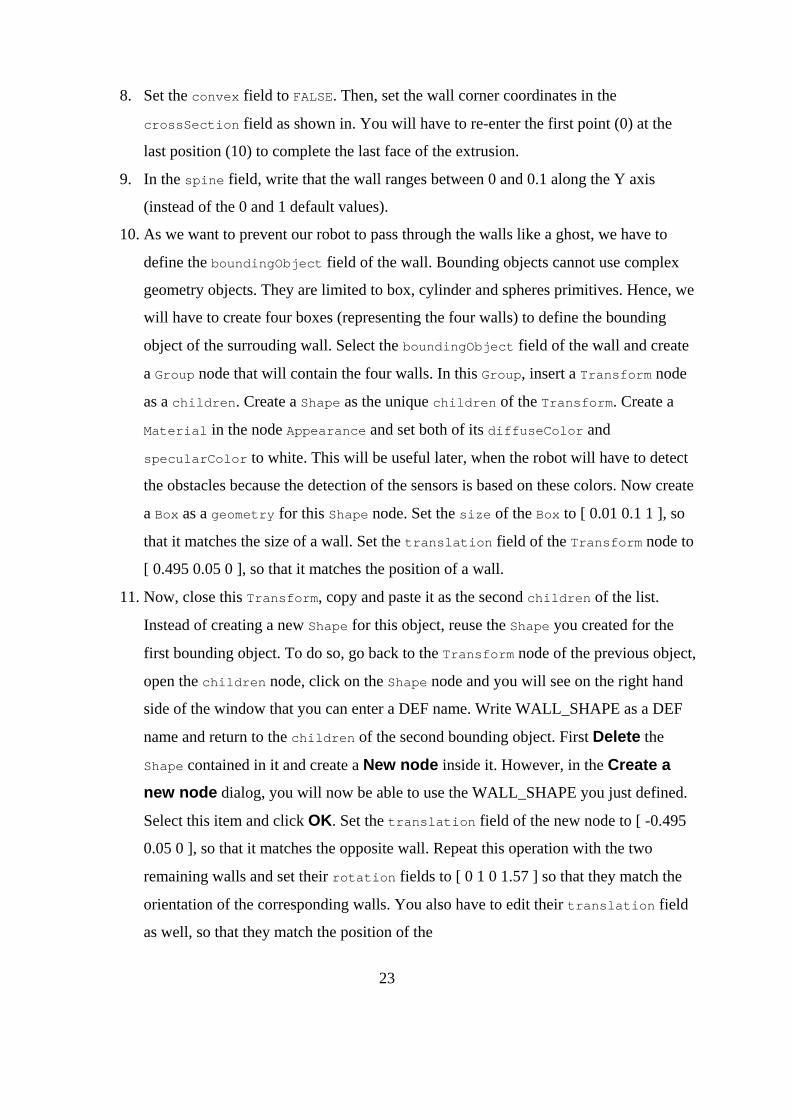
8. Set the convex field to FALSE. Then, set the wall corner coordinates in the
crossSection field as shown in. You will have to re-enter the first point (0) at the
last position (10) to complete the last face of the extrusion.
9. In the spine field, write that the wall ranges between 0 and 0.1 along the Y axis
(instead of the 0 and 1 default values).
10. As we want to prevent our robot to pass through the walls like a ghost, we have to
define the boundingObject field of the wall. Bounding objects cannot use complex
geometry objects. They are limited to box, cylinder and spheres primitives. Hence, we
will have to create four boxes (representing the four walls) to define the bounding
object of the surrouding wall. Select the boundingObject field of the wall and create
a Group node that will contain the four walls. In this Group, insert a Transform node
as a children. Create a Shape as the unique children of the Transform. Create a
Material in the node Appearance and set both of its diffuseColor and
specularColor to white. This will be useful later, when the robot will have to detect
the obstacles because the detection of the sensors is based on these colors. Now create
a Box as a geometry for this Shape node. Set the size of the Box to [ 0.01 0.1 1 ], so
that it matches the size of a wall. Set the translation field of the Transform node to
[ 0.495 0.05 0 ], so that it matches the position of a wall.
11. Now, close this Transform, copy and paste it as the second children of the list.
Instead of creating a new Shape for this object, reuse the Shape you created for the
first bounding object. To do so, go back to the Transform node of the previous object,
open the children node, click on the Shape node and you will see on the right hand
side of the window that you can enter a DEF name. Write WALL_SHAPE as a DEF
name and return to the children of the second bounding object. First Delete the
Shape contained in it and create a New node inside it. However, in the Create a new node dialog, you will now be able to use the WALL_SHAPE you just defined.
Select this item and click OK. Set the translation field of the new node to [ -0.495
0.05 0 ], so that it matches the opposite wall. Repeat this operation with the two
remaining walls and set their rotation fields to [ 0 1 0 1.57 ] so that they match the
orientation of the corresponding walls. You also have to edit their translation field
as well, so that they match the position of the
23

corresponding walls.
12. Close the tree editor, save your file as "my_mybot.wbt" and look at the result.
Fig.3.2
Thirdly, let us create the obstacles:
1. Select the last Solid node in the scene tree window (which is the wall) and click on
the insert after button.
2. Choose a Solid node.
3. Open this newly created Solid node from the + sign and type "green box" in its name
field.
24

4. Using the same technic as for the wall add first a Shape, then an Appearance and a
Material. For the color, let us make it green with a lighter green for the illuminated
parts.
5. Now create a Box node in the geometry field of the Shape and set its size to [ 0.23
0.1 0.1 ]. Set the DEF name of this geometry to BOX0.
6. To create the boundingObject of this object, create a Shape node and reuse the
previous DEF for the geometry. As for the wall, create also an Appearance and a
Material node and set the two colors to white.
7. Finally set the translation field to [ -0.05 0.05 -0.25 ] but let its rotation field to
the standard values.
8. Now repeat these steps to create the three remaining obstacles. First create the one
called "blue box" which has a geometry called BOX1 of [ 0.1 0.1 0.1 ], a
translation of [ 0.2 0.05 0.27 ] and a rotation of [ 0 1 0 0.31 ]. Then create the
one called "yellow box" which has a geometry called BOX2 of [ 0.05 0.1 0.3 ], a
translation of [ -0.2 0.05 0.15 ] and a rotation of [ 0 1 0 0.4 ]. Finally create the
one called "red box" which has a geometry called BOX3 of [ 0.15 0.1 0.08 ], a
translation of [ 0.42 0.05 -0.1 ] and a standard rotation. For all these objects, set
their colors accordingly with their names.
Robot
This subsection describes how to model the MyBot robot as a DifferentialWheels node
containing several children: a Transform node for the body, two Solid nodes for the wheels,
two DistanceSensor nodes for the infra-red sensors and a Shape node with a texture. The
origin
25
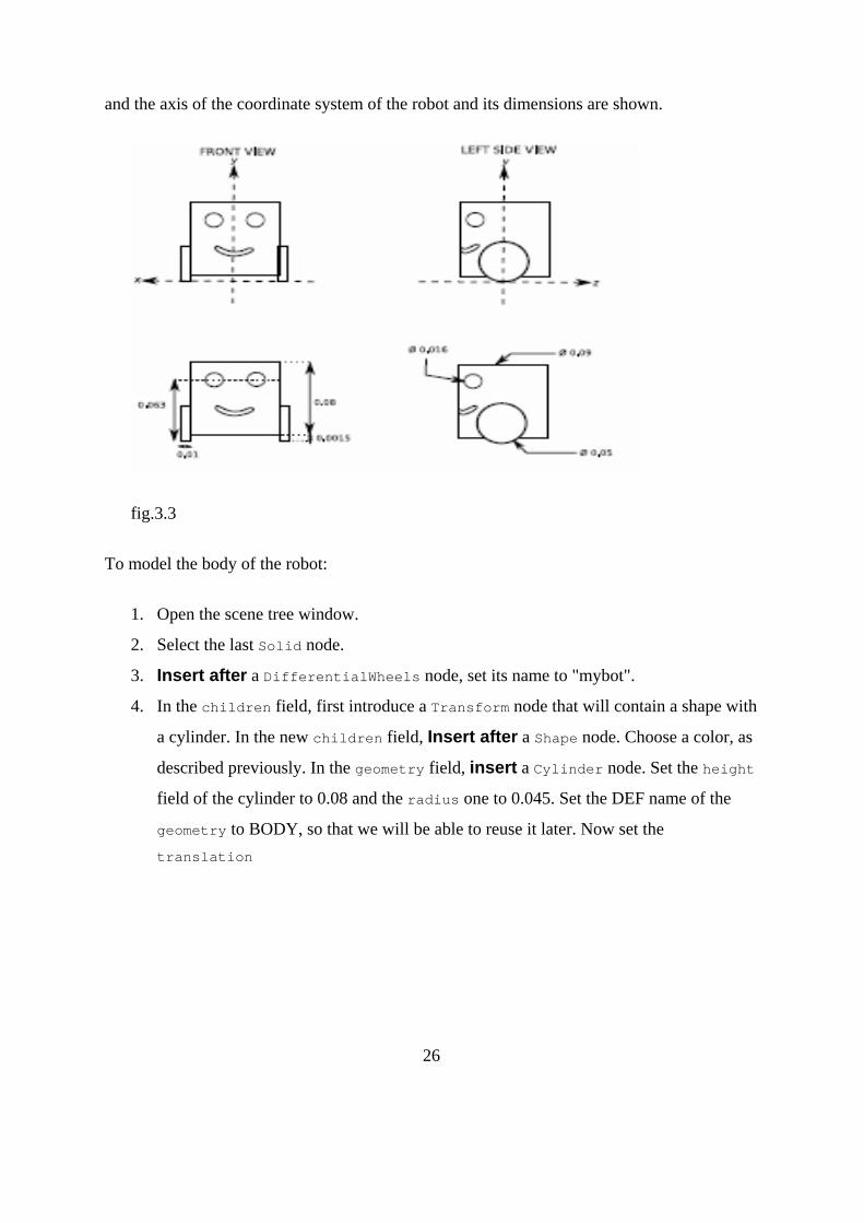
and the axis of the coordinate system of the robot and its dimensions are shown.
fig.3.3
To model the body of the robot:
1. Open the scene tree window.
2. Select the last Solid node.
3. Insert after a DifferentialWheels node, set its name to "mybot".
4. In the children field, first introduce a Transform node that will contain a shape with
a cylinder. In the new children field, Insert after a Shape node. Choose a color, as
described previously. In the geometry field, insert a Cylinder node. Set the height
field of the cylinder to 0.08 and the radius one to 0.045. Set the DEF name of the
geometry to BODY, so that we will be able to reuse it later. Now set the translation
26
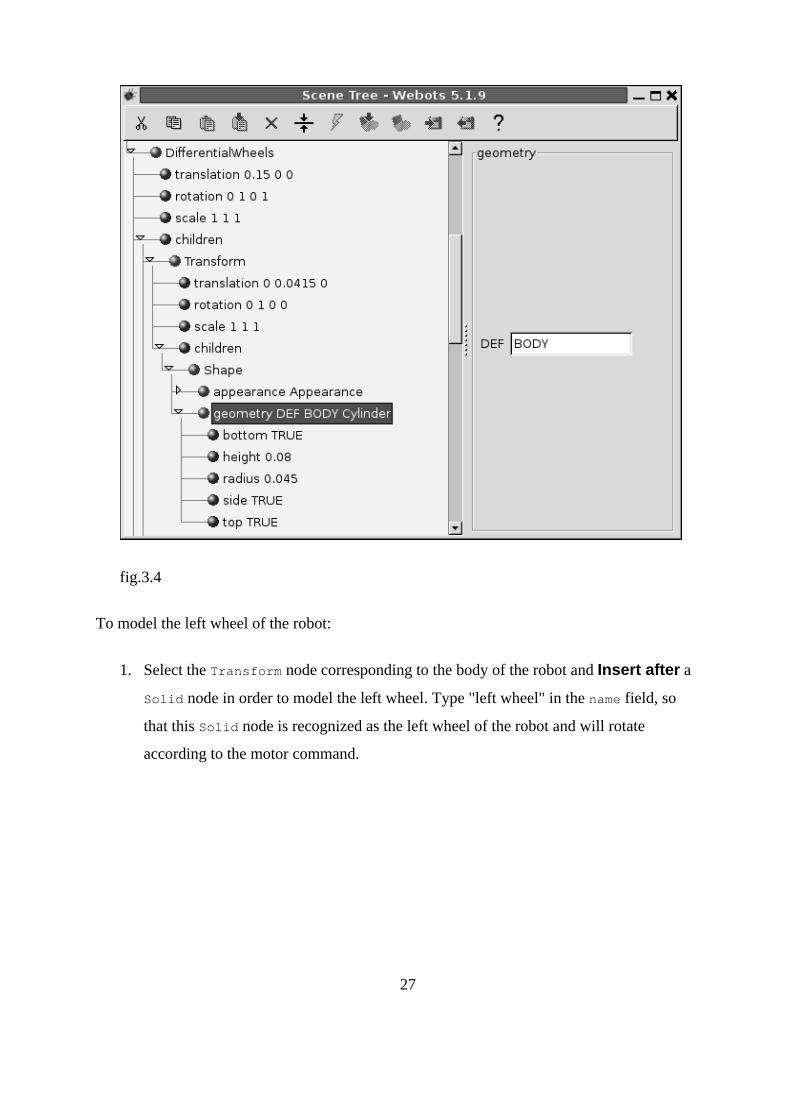
fig.3.4
To model the left wheel of the robot:
1. Select the Transform node corresponding to the body of the robot and Insert after a
Solid node in order to model the left wheel. Type "left wheel" in the name field, so
that this Solid node is recognized as the left wheel of the robot and will rotate
according to the motor command.
27

2. The axis of rotation of the wheel is x. The wheel will be made of a Cylinder rotated
of pi/2 radians around the z axis. To obtain proper movement of the wheel, you must
pay attention not to confuse these two rotations. Consequently, you must add a
Transform node to the children of the Solid node.
3. After adding this Transform node, introduce inside it a Shape with a Cylinder in its
geometry field. Don't forget to set an appearance as explained previously. The
dimensions of the cylinder should be 0.01 for the height and 0.025 for the radius.
Set the rotation to [ 0 0 1 1.57 ]. Pay attention to the sign of the rotation; if it is
wrong, the wheel will turn in the wrong direction.
4. In the Solid node, set the translation to [-0.045 0.025 0] to position the left wheel,
and set the rotation of the wheel around the x axis: [1 0 0 0].
5. Give a DEF name to your Transform: WHEEL; notice that you positioned the wheel
in translation at the level of the Solid node, so that you can reuse the WHEEL
Transform for the right wheel.
6. Close the tree window, look at the world and save it. Use the navigation buttons to
change the point of view.
To model the right wheel of the robot:
28

1. Select the left wheel Solid node and insert after another Solid node. Type "right
wheel" in the name field. Set the translation to [0.045 0.025 0] and the rotation to [1 0
0 0].
2. In the children, Insert after USE WHEEL. Press Return, close the tree window and
save the file. You can examine your robot in the world editor, move it and zoom on it.
The robot and its two wheels are shown .
fig.3.5
29

The two infra-red sensors are defined as two cylinders on the front of the robot body. Their
diameter is 0.016 m and their height is 0.004 m. You must position these sensors properly so
that the sensor rays point in the right direction, toward the front of the robot.
1. In the children of the DifferentialWheels node, insert after a DistanceSensor
node.
2. Type the name "ir0". It will be used by the controller program.
3. Let us attach a cylinder shape to this sensor: In the children list of the
DistanceSensor node, Insert after a Transform node. Give a DEF name to it:
INFRARED, which you will use for the second IR sensor.
4. In the children of the Transform node, insert after a Shape node. Define an
appearance and insert a Cylinder in the geometry field. Type 0.004 for the height
and 0.008 for the radius.
5. Set the rotation for the Transform node to [0 0 1 1.57] to adjust the orientation of the
cylinder.
6. In the DistanceSensor node, set the translation to position the sensor and its ray: [-
0.02 0.063 -0.042]. In the File menu, Preferences, Rendering, check the Display sensor rays box. In order to have the ray directed toward the front of the robot, you
must set the rotation to [0 1 0 2.07].
7. In the DistanceSensor node, you must introduce some values of distance
measurements of the sensors to the lookupTable field, according to. These values are:
Lookup Table [0 1024 0,
0.05 1024 0,
0.15 0 0]
30

Distance measurements of the MyBot sensors. (fig.3.6)
8. To model the second IR sensor, select the DistanceSensor node and Insert after a
new DistanceSensor node. Type "ir1" as a name. Set its translation to [0.02 0.063 -
0.042] and its rotation to [0 1 0 1.07]. In the children, insert after USE INFRARED.
In the lookupTable field, type the same values as shown above.
9. In order to detect better the obstacles, we will use two rays per DistanceSensor. To
do so, open both DistanceSensor nodes and set for each one the value of the
numberOfRay field to 2 and set also the aperture field to 1.
The robot and its two sensors are shown.
31

The DistanceSensor nodes of the MyBot robot (fig.3.7)
To paste a texture on the face of the robot:
1. Select the last DistanceSensor node and Insert after a Shape node.
2. Create an Appearance node in the appearance field. Create an ImageTexture node
in the texture field of this node, with the following URL:
3. "Mybot/mybot.png". This refers to an image file lying in the world’s directory.
4. In the geometry field, create an IndexedFaceSet node, with a Coordinate node in
the coord field. Type the coordinates of the points in the point field:
32
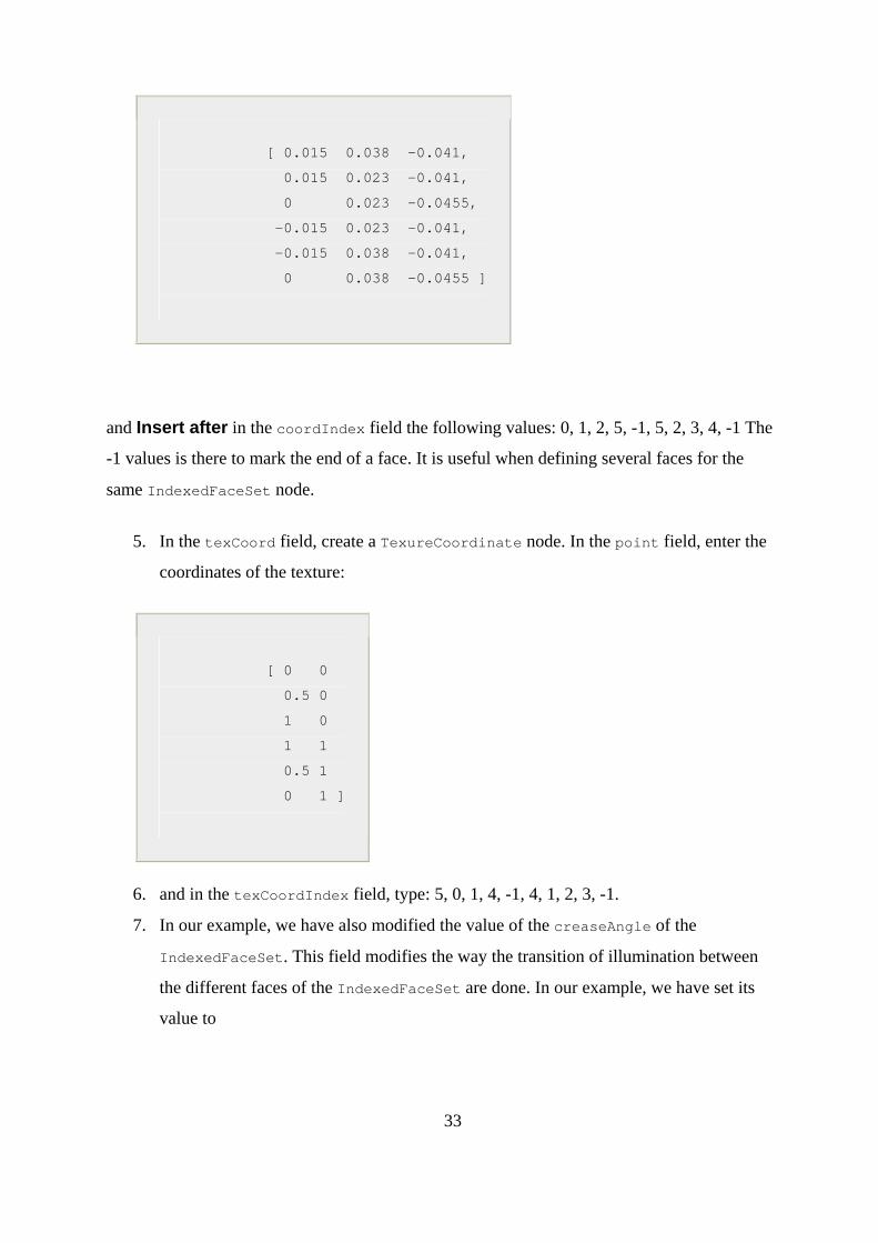
[ 0.015 0.038 -0.041,
0.015 0.023 -0.041,
0 0.023 -0.0455,
-0.015 0.023 -0.041,
-0.015 0.038 -0.041,
0 0.038 -0.0455 ]
and Insert after in the coordIndex field the following values: 0, 1, 2, 5, -1, 5, 2, 3, 4, -1 The
-1 values is there to mark the end of a face. It is useful when defining several faces for the
same IndexedFaceSet node.
5. In the texCoord field, create a TexureCoordinate node. In the point field, enter the
coordinates of the texture:
[ 0 0
0.5 0
1 0
1 1
0.5 1
0 1 ]
6. and in the texCoordIndex field, type: 5, 0, 1, 4, -1, 4, 1, 2, 3, -1.
7. In our example, we have also modified the value of the creaseAngle of the
IndexedFaceSet. This field modifies the way the transition of illumination between
the different faces of the IndexedFaceSet are done. In our example, we have set its
value to
33

0.9 so that the illumination transition is smooth between the two faces.
8. The texture values are shown.
fig.3.8 Defining the texture of the MyBot robot
To finish with the DifferentialWheels node, you must fill in a few more fields:
1. In the controller field, select "mybot_simple" which should appear in the popup
controller list when you press the file selection button. It is used to determine which
controller program controls the robot.
2. The boundingObject field can contain a Transform node with a Cylinder, as a
cylinder as bounding object for collision detection is sufficient to bound the MyBot
robot. Create a Transform node in the boundingObject field, with the translation
set to [ 0 0.0415 0 ] and for the Cylinder node in its children simply reuse the
BODY node defined
34

previously.
3. In the axleLength field, enter the length of the axle between the two wheels: 0.09
4. In the wheelRadius field, enter the radius of the wheels: 0.025.
5. Values for other fields and the finished robot in its world are shown.
fig.3.9 The other fields of the DifferentialWheels node
A simple controller
This controller is very simple. The controller program simply reads the sensor values and sets
the two motors' speeds, in such a way that MyBot avoids the obstacles.
Below is the source code for the mybot_simple.c controller:
35
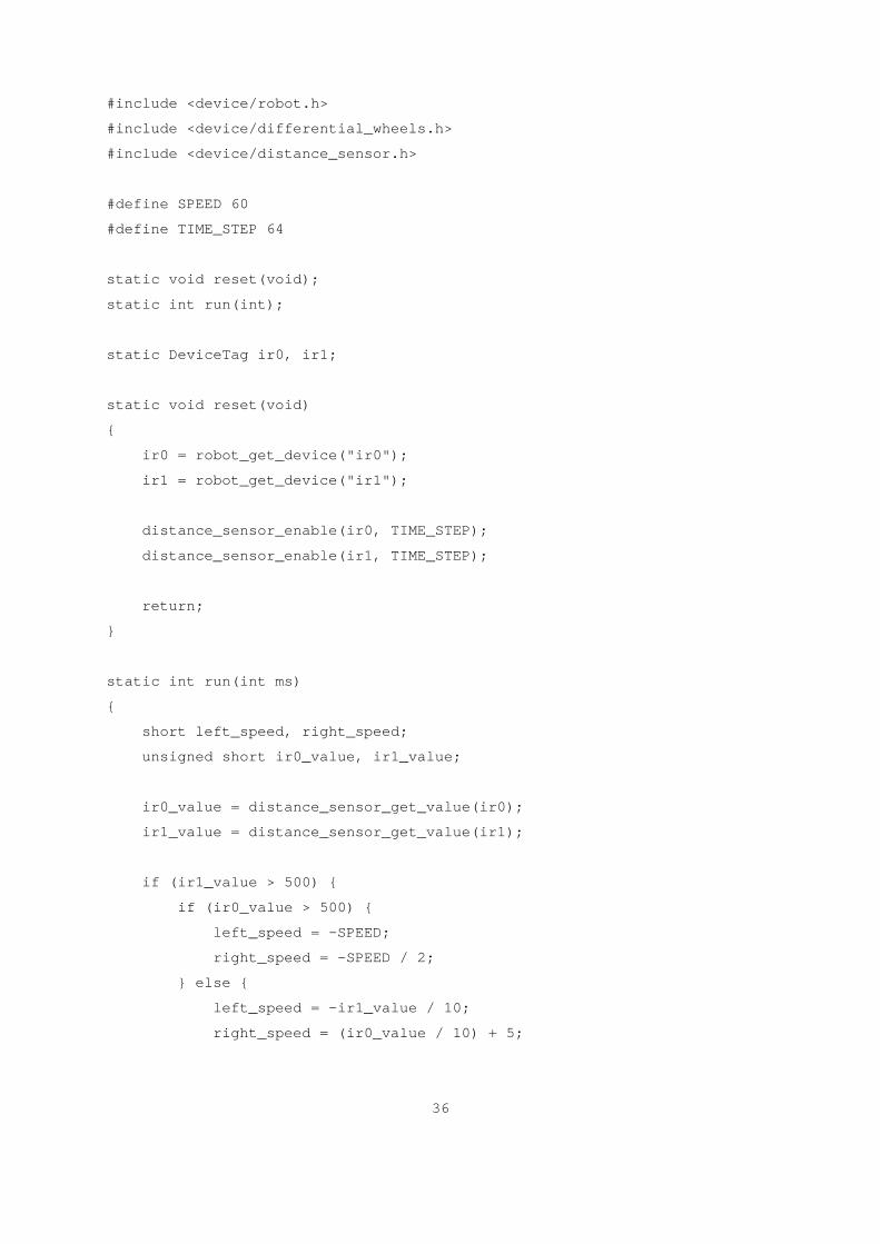
#include <device/robot.h>
#include <device/differential_wheels.h>
#include <device/distance_sensor.h>
#define SPEED 60
#define TIME_STEP 64
static void reset(void);
static int run(int);
static DeviceTag ir0, ir1;
static void reset(void)
{
ir0 = robot_get_device("ir0");
ir1 = robot_get_device("ir1");
distance_sensor_enable(ir0, TIME_STEP);
distance_sensor_enable(ir1, TIME_STEP);
return;
}
static int run(int ms)
{
short left_speed, right_speed;
unsigned short ir0_value, ir1_value;
ir0_value = distance_sensor_get_value(ir0);
ir1_value = distance_sensor_get_value(ir1);
if (ir1_value > 500) {
if (ir0_value > 500) {
left_speed = -SPEED;
right_speed = -SPEED / 2;
} else {
left_speed = -ir1_value / 10;
right_speed = (ir0_value / 10) + 5;
36

} else if (ir0_value > 500) {
left_speed = (ir1_value / 10) + 5;
right_speed = -ir0_value / 10;
} else {
left_speed = SPEED;
right_speed = SPEED;
}
differential_wheels_set_speed(left_speed, right_speed);
return TIME_STEP;
}
int main()
{
robot_live(reset);
robot_run(run);
return 0;
}
SUMMARY:
This program is made up of two functions as in any C program,main() and reset() which is a
call back function used for getting references to the sensors of the robot.This function will be
called each time to reread the references to the device called DeviceTags.ex:ir0,ir1.Initially
they have to be assigned.
The updates for the device happen in 64 milliseconds.
Finally the main() function enters an endless loop in which the sensor values are read,motor
speeds are computed according to sensor values and assigned to the motors and encoders are
37

read and reset if needed
Robot_run(run):This function runs the simulation repeatedly after the number of milliseconds
that is passed as argument.
38
Chapter 4 Result and Discussion A simple controller Output Conclusion

Result and Discussion
fig.4.1
This figure shows the world in which the bot is needed to operate. Here we see the floor is
illuminated with four lights .and the floor is bounded by four walls so that on simulation the
bot doesn’t fall out of the arena.
fig.4.2 39
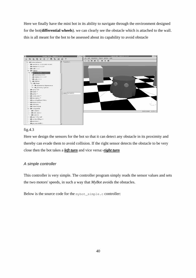
Here we finally have the mini bot in its ability to navigate through the environment designed
for the bot(differential wheels). we can clearly see the obstacle which is attached to the wall.
this is all meant for the bot to be assessed about its capability to avoid obstacle
fig.4.3
Here we design the sensors for the bot so that it can detect any obstacle in its proximity and
thereby can evade them to avoid collision. If the right sensor detects the obstacle to be very
close then the bot takes a left turn and vice versa:-right turn
A simple controller
This controller is very simple. The controller program simply reads the sensor values and sets
the two motors' speeds, in such a way that MyBot avoids the obstacles.
Below is the source code for the mybot_simple.c controller:
40

#include <device/robot.h>
#include <device/differential_wheels.h>
#include <device/distance_sensor.h>
#define SPEED 60
#define TIME_STEP 64
static void reset(void);
static int run(int);
static DeviceTag ir0, ir1;
static void reset(void)
{
ir0 = robot_get_device("ir0");
ir1 = robot_get_device("ir1");
distance_sensor_enable(ir0, TIME_STEP);
distance_sensor_enable(ir1, TIME_STEP);
return;
}
static int run(int ms)
{
short left_speed, right_speed;
unsigned short ir0_value, ir1_value;
ir0_value = distance_sensor_get_value(ir0);
ir1_value = distance_sensor_get_value(ir1);
if (ir1_value > 500) {
if (ir0_value > 500) {
left_speed = -SPEED;
right_speed = -SPEED / 2;
} else {
left_speed = -ir1_value / 10;
41

right_speed = (ir0_value / 10) + 5;
}
} else if (ir0_value > 500) {
left_speed = (ir1_value / 10) + 5;
right_speed = -ir0_value / 10;
} else {
left_speed = SPEED;
right_speed = SPEED;
}
differential_wheels_set_speed(left_speed, right_speed);
return TIME_STEP;
}
int main()
{
robot_live(reset);
robot_run(run);
return 0;
}
OUTPUT
Fig.4.4
The output is a complete bot which can easily avoid obstacle and can navigate through the
environvent with its all translational and rotational capabilities
42

Conclusion: This program is made up of two functions as in any C program,main() and
reset() which is a call back function used for getting references to the sensors of the
robot.This function will be called each time to reread the references to the device called
DeviceTags.ex:ir0,ir1.Initially they have to be assigned.
The updates for the device happen in 64 milliseconds.
Finally the main() function enters an endless loop in which the sensor values are read,motor
speeds are computed according to sensor values and assigned to the motors and encoders are
read and reset if needed.
Robot_run(run):This function runs the simulation repeatedly after the number of milliseconds
that is passed as argument.
43

Chapter 5 Conclusion

Conclusion The swarm intelligence is widely used in space explorations, rescue in
collapsed buildings, shop floor cleaning, shop floor industries, process industries and many
others.
The hole-avoidance task represents the first step toward the solution of
more difficult problems. We will extend this work in order to obtain controllers that can pass
over holes that are sufficiently small, while avoiding falling into holes that are too big to be
traversed by the swarm-bot.additionally; we plan to study problems that belong to the all-
terrain navigation family, such as coping with uneven terrains. In these perspectives, physical
connections among s-bots become an essential feature to be exploited. Finally, we intend to
investigate functional self-assembly for all terrain navigation, that is, the problem of forming
and disbanding a swarm-bot with a functional shape for the particular environmental
conditions and task to be performed, in order to maximize the efficiency in the navigation
Results demonstrate the traction sensor to be a powerful mechanism for
achieving coordination in the swarm-bot. The traction sensor allows the swarm-bot to exploit
the complex dynamics arising from interactions between individual s-bots and between the s-
bots and the environment. It provides robustness and adaptively features with respect to
environmental or structural changes of the swarm-bot. Besides, traction forces are used as a
sort of communication of the presence of a hazard, allowing the group as a whole and not
only the s-bots that perceive the hole to change direction of motion when heading toward a
hole. Finally, the traction sensor can work also as a distributed bumper for the swarm-bot,
allowing collective obstacle avoidance
44

The solutions found by evolution are simple and in many cases they work
in different environmental situations. The obtained results suggest that evolution is a suitable
tool for synthesizing controllers for a group of homogeneous robots. In this case, evolution
was able to produce a self-organizing system that relies on simple and general rules, a system
that is consequently robust to environmental changes and to the number of s-bots involved in
the experiment.
45

Chapter 6 Appendix Program Summary

APPENDIX Program for simple controller #include <device/robot.h> #include <device/differential_wheels.h> #include <device/distance_sensor.h> #define SPEED 60 #define TIME_STEP 64 static void reset(void); static int run(int); static DeviceTag ir0, ir1; static void reset(void) { ir0 = robot_get_device("ir0"); ir1 = robot_get_device("ir1"); distance_sensor_enable(ir0, TIME_STEP); distance_sensor_enable(ir1, TIME_STEP); return; } static int run(int ms) { short left_speed, right_speed; unsigned short ir0_value, ir1_value; ir0_value = distance_sensor_get_value(ir0); ir1_value = distance_sensor_get_value(ir1); if (ir1_value > 500) { if (ir0_value > 500) { left_speed = -SPEED; right_speed = -SPEED / 2; } else { left_speed = -ir1_value / 10; right_speed = (ir0_value / 10) + 5; } } else if (ir0_value > 500) { left_speed = (ir1_value / 10) + 5; right_speed = -ir0_value / 10; } else { left_speed = SPEED; right_speed = SPEED; } differential_wheels_set_speed(left_speed, right_speed); return TIME_STEP;
46

} int main() { robot_live(reset); robot_run(run); return 0; }
SUMMARY:
This program is made up of two functions as in any C program,main() and reset() which is a call back function used for getting references to the sensors of the robot.This function will be called each time to reread the references to the device called DeviceTags.ex:ir0,ir1.Initially they have to be assigned.
The updates for the device happen in 64 milliseconds.
Finally the main() function enters an endless loop in which the sensor values are read,motor speeds are computed according to sensor values and assigned to the motors and encoders are read and reset if needed.
Robot_run(run):This function runs the simulation repeatedly after the number of milliseconds that is passed as argument.
47

Chapter 7 References
References
[1] G. Baldassarre, S. Nil , and D. Parisi. Evolution of collective behavior in a team of
physically linked robots. In R. Gunther, A. Guillot, and J.-A. Meyer, editors, Applications of
Evolutionary Computing - Proceedings of the Second European Workshop on evolutionary
Robotics (EvoWorkshops2003: EvoROB), pages 581{592. Springer-Verlag, Berlin,
Germany, 2003. [2] S. Camazine, J.-L. Deneubourg, N. Franks, J. Sneyd, G. Theraulaz, and
E. Bonabeau. Self-Organization in Biological Systems. Princeton University Press, Princeton,
NJ, 2001. [3] A. Castano, W. S en, and P. Will. CONRO: Towards deployable robots with
inter-robot metamorp ic capabilities. Autonomous Robots, 8:309{324, 2000. [4] M. Dorigo,
V. Trianni, E. S�ahin, R. Gro�, T. H. Labella, G. Baldassarre, S. Nol , J.-L. Deneubourg, F.
Mondada, D. Floreano, and L. M. Gambardella. Evolving self-organizing behaviors for a
swarm-bot. Autonomous Robots, 17(2{ 3):223{245, 2004.
[5] S. Hirose, . Shirasu, and E. F. Fukushima. Proposal for cooperative robot \Gunryu"
composed of autonomous segments. Robotics and Autonomous Systems,
17:107{118, 1996. [6] A. Lioni, C. Sauwens, G. Theraulaz, and J.-L. Deneubourg. Chain
formation in -cophilla longinoda. Journal of Insect Behaviour, 15:679{696, 2001. [7] L.
Matthies, E. Gat, R. Harrison, B. Wilcox, R. Volpe, and T. Litwin. Mars microrover
navigation: Performance evaluation and enhancement. Autonomous Robots, 2(4):291{312,
1995. [8] F. Mondada, G. C. Pettinaro, A. Guignard, I. V. Kwee, D. Floreano, J.-L.
Deneubourg, S. Nol , L. M. Gambardella, and M. Dorigo. SWARM-BOT: A new distributed
robotic concept. Autonomous Robots, 17(2{3):193{221, 2004. [9] S. Nol and D. Floreano.
Evolutionary Robotics: The Biology, Intelligence, and Technology of Self-Organizing
Machines. MIT Press/Bradford Books, Cambridge, MA, 2000.
[10] M. Quinn, L. Smith, G. Mayley, and P. Husband. Evolving teamwork and role allocation
with real robots. In R. K. Standish, M. A. Bedau, and H. A. Abbass, editors, Proceedings of
the 8th International Conference on Arti cial Life, pages 302{311. MIT Press, Cambridge,
MA, 2002. [11] K. St�y, W.-M. Shen, and P. Will. Global locomotion from local interaction
in self-recon
48
gurable robots. In W. M. Shen, C. Torras, and H. Yuasa, editors, Proc. of the 7th International
Conference on Intelligent Autonomous Systems (IAS-7), pages 09{316. IOS Press,
Amsterdam, The Netherlands, Mar 25-27
2002.
1. G. Baldassarre, S. Nol , and D. Parisi. Evolution of collective behaviour in a team of
physically linked robots. In R. G�unther, A. Guillot, and J.-A. Meyer, editors, Proceedings
of the Second European Workshop on Evolutionary Robotics (EvoWorkshops2003:
EvoROB), Lecture Notes in Computer Science, pages 581{ 592. Springer Verlag, Berlin,
Germany, 2003.
2. G. Baldassarre, S. Nol , and D. Parisi. Evolving mobile robots able to display collective
behaviour. Arti cial Life, 9:255{267, 2003.
3. E. Bonabeau, M. Dorigo, and G. Theraulaz. Swarm Intelligence: From Natural to Articial
Systems. Oxford University Press, New York, NY, 1999.4. A. Castano, W.-M. Shn, and P.
Will. CONRO: Towards deployable robots with inter-robot metamorphic capabilities.
Autonomous Robots, 8:309{324, July 2000.
5. M. Dorigo and E. S�ahin. Swarm robotics { special issue editorial. Autonomous robots,
17(2{3):111{113, 2004.
6. M. Dorigo, V. Trianni, E. S�ahin, R. Gro�, T. H. Labella, G. Baldassarre, S. Nol, J.-L.
Deneubourg, F. Mondada, D. Floreano, and L. M. Gambardella. Evolving self-organizing
behaviors for a swarm-bot. Autonomous Robots, 17(2{3):223{245, 2004.
7. R. Gro� and M. Dorigo. Cooperative transport of objects of di
erent shapes andsizes. In M. Dorigo, M. Birattari, C. Blum, L. M. Gambardella, F. Mondada,
andT. St�utzle, editors, Proceedings of ANTS 2004 { Fourth International Workshopon Ant
Colony Optimization and Swarm Intelligence, volume 3172 of Lecture Notesin Computer
Science, pages 107{118. Springer Verlag, Berlin, Germany, 2004.
8. R. Gro� and M. Dorigo. Evolving a cooperative transport behavior for two simple robots.
In P. Liardet, P. Collet, C. Fonlupt, E. Lutton, and M. Schoenauer, editors, Arti cial Evolution
{ 6th International Conference, Evolution Arti cielle, EA
49

2003, Marseille, France, October 2003, volume 2936 of Lecture Notes in Computer Science,
pages 305{317. Springer Verlag, Berlin, Germany, 2004.
9. R. Gro� and M. Dorigo. Group transport of an object to a target that only some group
members may sense. Technical Report TR/IRIDIA/2004-4, Universit�e Libre de Bruxelles,
Belgium, 2004. To appear in the Eight International Conference on Parallel Problem Solving
from Nature (PPSN VIII), September 18-22, 2004,
Birmingham, UK.
10. P. Khosla, B. Brown, C. Paredis, B. Grabowski, L. Navarro, C. Bererton, and M.
Vandeweghe. Millibot Report. Report on millibot project, DARPA contract DABT63-97-1-
0003, Carnegie Mellon University, Pittsburgh, Pennsylvania, USA, April 2002.
11. T.H. Labella, M. Dorigo, and J.-L. Deneubourg. E ciency and task allocation in prey
retrieval. In A.J. Ijspeert, M. Murata, and N. Wakamiya, editors, Proceedings of the First
International Workshop on Biologically Inspired Approaches to Advanced Information
Technology (Bio-ADIT2004), Lecture Notes in Computer Science, pages 32{47. Springer
Verlag, Heidelberg, Germany, 2004.
12. T.H. Labella, M. Dorigo, and J.-L. Deneubourg. Self-organised task allocation in a swarm
of robots. Technical Report TR/IRIDIA/2004-6, Universit�e Libre de Bruxelles, Belgium,
2004. To appear in the 7th International Symposium on Distributed Autonomous Robotic
Systems (DARS04), June 23-25, 2004, Toulouse, France.
13. F. Mondada, G. C. Pettinaro, A. Guignard, I. V. Kwee, D. Floreano, J.-L. Deneubourg, S.
Nol , L. M. Gambardella, and M. Dorigo. SWARM-BOT: A new distributed robotic concept.
Autonomous Robots, 17(2{3):193{221, 2004.
14. F. Mondada, G. C. Pettinaro, I. W. Kwee, A. Guignard, L. M. Gambardella, . Floreano, S.
Nol , J.-L. Deneubourg, and M. Dorigo. SWARM-BOT: A swarm f autonomous mobile
robots with self-assembling capabilities. In C.K. Hemelrijk nd E. Bonabeau, editors,
Proceedings of the International Workshop on Selforganisation nd Evolution of Social
Behaviour, pages 307{312, Monte Verit�a, Ascona, witzerland, September 8{13, 2002. 15.
E. S�ahin, T. H. Labella, V. Trianni, J.-L. Deneubourg, P. Rasse, D. Floreano, L. M.
Gambardella, F. Mondada, S. Nol , and M. Dorigo. SWARM-BOT:
50
Pattern
formation in a swarm of self-assembling mobile robots. In Proceedings of the EEE
International Conference on Systems, Man and Cybernetics. IEEE Press, iscataway, NJ,
October 2002.
16. V. Trianni, R. Gro�, T. H. Labella, E. S�ahin, and M. Dorigo. Evolving aggregation
behaviors in a swarm of robots. In W. Banzhaf, T. Christaller, P. Dittrich, J. T.
Kim, and J. Ziegler, editors, Proceedings of the Seventh European Conference on
Arti cial Life, volume 2801 of Lecture Notes in Arti cial Intelligence, pages 865{
874. Springer Verlag, Berlin, Germany, 2003.
17. V. Trianni, S. Nol , and M. Dorigo. Hole avoidance: Experiments in coordinated
motion on rough terrain. In F. Groen, N. Amato, A. Bonarini, E. Yoshida, and
B. Kr�ose, editors, Intelligent Autonomous Systems 8, pages 29{36. IOS Press,
Amsterdam,The Netherlands, 2004.
18. V. Trianni, E. Tuci, and M. Dorigo. Evolving functional self-assembling in a swarm
of autonomous robots. In S. Schaal, A. Ijspeert, A. Billard, S. Vijayakamur, J. Hallam,
and J-A. Meyer, editors, From Animals to Animats 8. Proceedings of the Eight International
Conference on Simulation of Adaptive Behavior (SAB04), pages 405{
414. MIT Press, Cambridge, MA, 2004.
51