paths and matrices of propagation - fraunhofer isst · paths and matrices of propagation ... this...
TRANSCRIPT

Paths and Matrices of Propagation
A concept to trace the impact of modifications onsoftware components 1
Caroline Berthomieu, Ralf-Detlef Kutsche, Stefan [email protected], [email protected], [email protected]
64/02December 2002
1 This work has been supported by the German Federal Ministry of Education and Research (Bun-desministerium für Bildung und Forschung BMBF) as part of the research project Continuous En-gineering for Evolutionary I&C Infrastructures (Kontinuierliches Engineering für evolutionäre IuK-Infrastrukturen KONTENG) under grant 01IS901C


Abstract
Because of growing market requirements, software systems have become comple-xer than ever. Recently, component-based software engineering has been presentedas a solution to face to this problem. A well defined component model makes com-ponent based software systems robust and long-lasting. Nevertheless, due to theircomplexity, those systems are still difficult to maintain or evolve. Indeed, the impactof a modification grows proportionally with the complexity of the system.In this paper, paths of propagation and the concept of matrix of propagation will beintroduced as a technique to trace the impact of required modifications on the system.More precisely, it guides the engineer by tracing the impact of a given modification ofa component on other components of the system.
Paths and Matrices of Propagation 1

Contents
Contents
1 Introduction 4
2 Component concepts 5
2.1 Structure of a component 5
2.2 Views on component 6
2.3 Component dependencies 8
2.4 Compositionality of components 11
3 The concept of »matrix of propagation« 12
3.1 Notations and semantics 12
3.2 The matrix of propagation as assembly of several concepts 14
3.3 Propagation paths 16
3.4 Example 17
3.4.1 Addition of a service 18
3.4.2 Deletion of a service 19
3.4.3 Modification of a service 22
4 Conclusion 27
5 Bibliography 28
Paths and Matrices of Propagation 2

List of Figures
List of Figures
1 Structure of a component 5
2 Blackbox, greybox and whitebox views 7
3 Detailed whitebox view 7
4 Detailed greybox view 8
5 »Use-relation« between two components 9
6 Direct and indirect dependencies in a component 9
7 Compositionality of components 11
8 How the matrix can be read 13
9 The matrix of propagation 15
10 Subsystem S 17
11 Subsystem S in a Greybox view 18
Paths and Matrices of Propagation 3

Introduction
1 Introduction
Software systems have become more complex than ever. Today engineers face thebiggest challenge to bring out dependable software systems with new technologiesand features, but within a short time. These systems should also be easily modifiablewithout to become any harm. One promising solution is component based softwareengineering(CBSE). CBSE advocates the production of software systems by usingstandardized, prefabricated, stable components. Using CBSE brings down the overalltime and cost without having to compromise on quality.
It is well known that software systems often have a longer life than expected. Sincethe market requirements change continuously, software systems need to be modifiedappropriately to keep in pace with this development. This is also valid in the case ofsystems built out of components. A minor change or replacement of a componentcould produce undesirable impacts on the system. It is therefore inevitable to closelystudy the effects of the modification of any component on the whole system.
This paper discusses the problems faced during the lifecycle of a component basedsoftware system. Here the concept of the matrix of propagation is presented as asolution to diagonize the problems faced while modifying components of a system.
Paths and Matrices of Propagation 4

Component concepts
2 Component concepts
A component model defines a set of standards for the structure of components andthe interaction between them. In component model considered in the project »«, com-ponents will also be considered to be »composable« [2, 3].In this section, we will first discuss about the structure of components, then threedifferent views of components will be presented. In a third part, the notion of relationbetween components or between parts of components will be developed. Finally, thecompositionality of components will be discussed.
2.1 Structure of a component
Components are coherent software units which can be put together in order to con-stitute a complete »composable« software system. They encapsulate a specific func-tionality of the system. In this way, they have well defined interfaces which describetheir functionality, i.e. the services they provide. A service can be defined as a typeoffered by a specific component. Each component implements a type and managesa set of instances of this type [12]. The interfaces allow to hide the implementationdetails of the component. Due to this implementation hiding, it is easier to modify orto replace a component.
In the CSE component model, a component consists of 3 parts, namely an exportinterface, an import interface and a body.
Export
Body
Import
Figure 1 Structure of a component
The export interface
The export interface holds the functionality of the component. It contents the ser-vices that the component provides to its environment, i.e. the services that it offers to
Paths and Matrices of Propagation 5

Component concepts
other components. Those services are implemented in the body of the component,or in another component. In the second case, the service is imported from the othercomponent via the import Interface.
The import interface
The import interface states the requirements of the component on other components.It specifies services that are needed by the body in order to implement properly theservices provided by the component (i.e the exported services). In this way the im-port interface shows the dependency of the component on other components in itsenvironment.Note that every service of the import interface is considered to be used in the body.
The body
The body of a component contains the implementation of the services that are provi-ded in the export interface. In this way, the implementation details of the componentare transparent to the user.
2.2 Views on component
Generally speaking there exist 3 views on components, namely the blackbox, thewhitebox and the greybox view. These views are based on the visibility of the imple-mentation details of a component to a user.
The blackbox view
In this view, the user does not get any information about the body of the component.He only sees which services the component offers and requires, i.e. only the exportand the import interfaces are visible.
The whitebox view
In contrast to the blackbox view, the implementation details of the component appearsto the user. Here, the export and import interfaces, as well as the body are completelyvisible (see figure 3).
Paths and Matrices of Propagation 6

Component concepts
Export
Import
Body
Export
Import
Body
Export
Import
Body
Figure 2 Blackbox, greybox and whitebox views
Component A
SAEE11 SAEE22 SAEE33
SAII11 SAII22 SAII33
SA1EE11
SA1II11 SA1II22 SA1II33
AA11 AA22SA2EE11SA1EE22
Figure 3 Detailed whitebox view
Paths and Matrices of Propagation 7
Component concepts
The greybox view
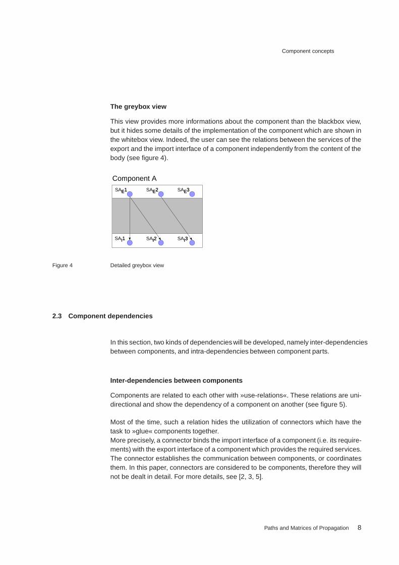
This view provides more informations about the component than the blackbox view,but it hides some details of the implementation of the component which are shown inthe whitebox view. Indeed, the user can see the relations between the services of theexport and the import interface of a component independently from the content of thebody (see figure 4).
Component A
SAII11 SAII22 SAII33
SAEE11 SAEE22 SAEE33
Figure 4 Detailed greybox view
2.3 Component dependencies
In this section, two kinds of dependencies will be developed, namely inter-dependenciesbetween components, and intra-dependencies between component parts.
Inter-dependencies between components
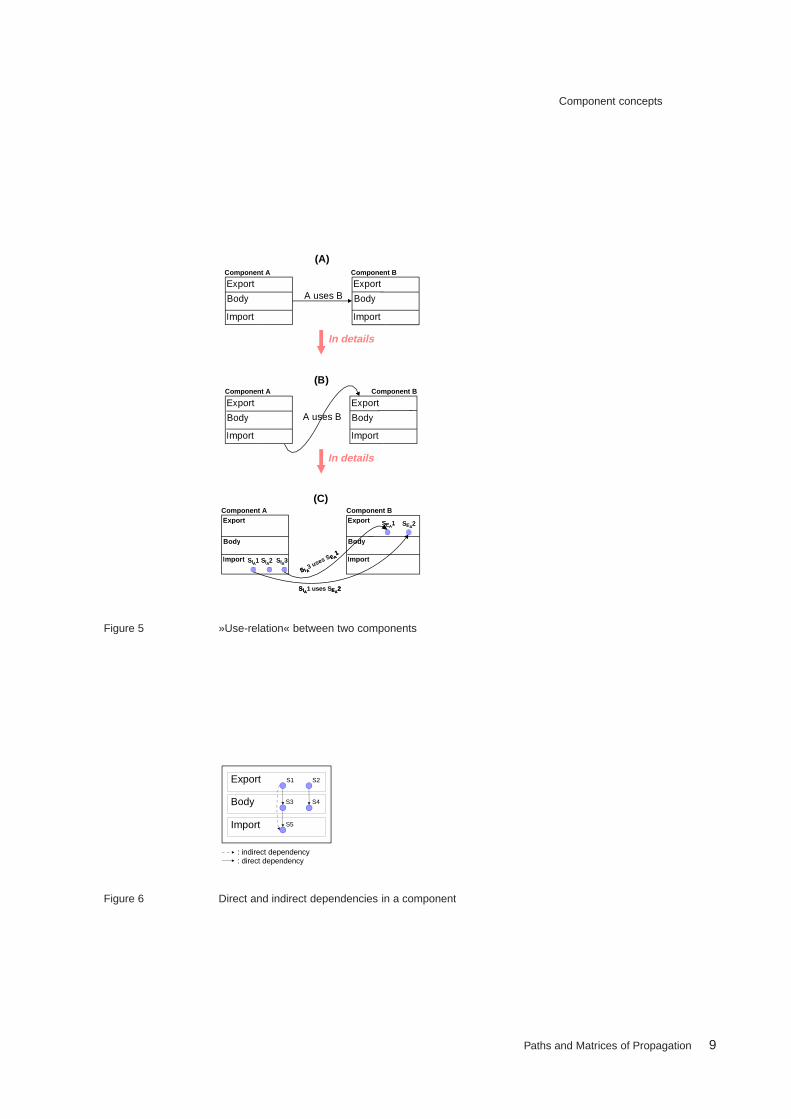
Components are related to each other with »use-relations«. These relations are uni-directional and show the dependency of a component on another (see figure 5).
Most of the time, such a relation hides the utilization of connectors which have thetask to »glue« components together.More precisely, a connector binds the import interface of a component (i.e. its require-ments) with the export interface of a component which provides the required services.The connector establishes the communication between components, or coordinatesthem. In this paper, connectors are considered to be components, therefore they willnot be dealt in detail. For more details, see [2, 3, 5].
Paths and Matrices of Propagation 8
Component concepts
Export
Import
Body
Compon ent A
Export
Import
Body
Compon ent B
A uses B
In details
Export
Import
Body
Compon ent A
Export
Import
Body
Compon ent B
A uses B
In details
Export
Import
Body
Compon ent AExport
Import
Body
Compon ent B
SSIIAA1 uses SEEAA22
SSEEAA11 SSEEAA
22
SSIIAA11 SSIIAA33SSIIAA22
SSIIAA3 uses SEEAA
11
(A)
(B)
(C)
Figure 5 »Use-relation« between two components
Export
Body
Import
S1 S2
S4S3
S5
: indirect dependency: direct dependency
Figure 6 Direct and indirect dependencies in a component
Paths and Matrices of Propagation 9
Component concepts
Intra-dependencies between the parts of a component
There are two kinds of dependencies between the parts of a component (see figure6).
Direct dependencies
The direct dependencies bind the services of the export or import interface with thebody of of a component. They represent the dependencies shown in the whiteboxview of a component (see figures 6) and 3. There are two kinds of direct dependen-cies, namely:
1 Direct dependencies between the export interface and the body:All the services provided by the component are defined in the export interface.Each of them is directly dependent on its implementation, which is made in thebody of the component.
2 Direct dependencies between the body and the import interface of a component:Some components have requirements on other components. These requirementsare services which are imported through the import interface of the component.The body of the component needs the imported services to properly achieve theimplementation of its functionality (i.e. the services in its export interface). So, thebody is directly dependent on the services of the import interface.
Indirect dependencies
The indirect dependencies are used in the greybox view of components. In order toget a quick overview of a component, it is sometimes relevant to see the relationsbetween the services of the export and the import interface, without considering thewhole implementation made in the body. In this way, indirect dependencies can beseen as an abstraction of several direct dependencies which bind a service in theexport interface to a service in the import interface (see figures 4 and 6).
Paths and Matrices of Propagation 10

Component concepts
2.4 Compositionality of components
The composition of components is the art of combining components with each otherin order to create a bigger component (see figure 7). There are two categories ofcomponents in component systems:
– The composite components: they contain other composite components (subsys-tems) as well as non-compositional component. They can also be dependent onother components. In this way, a subsystem can be also seen as a compositecomponent.
– the non-compositional components: their body contain the detail of their imple-mentation (e.g. code), but no other component.Note that in this paper, we will always consider non-compositional components ina greybox or blackbox view in order to hide the details of their body.
The compositionality of components is a good technique to achieve certain levels ofabstraction of the system. The designer has the possibility to hide details of his modelby considering a black box or a more precise greybox view (see chapter 2.2) of someof the composite components of the model.
Compon ent AExport
Body
Figure 7 Compositionality of components
Paths and Matrices of Propagation 11
The concept of »matrix ofpropagation«
3 The concept of »matrix of propagation«
At a certain stage of a software lifecycle, designers or developers need to modify so-me components. Before the modification is actually done, they need to check whetherthe component they want to modify is dependent on other components or vice versa.This verification would avoid dire consequences on the whole component system.The aim of the matrix of propagation is to guide the tracing of dependencies betweencomponents, and to give to those persons a better view of the impacts of the modifi-cation of a component on the other components of the system. Thus the matrix helpsthe process of evolution of the whole software.Note that in this chapter, the component-based systems which are taken into consi-deration (before modification) are assumed to be consistent and reduced:
– Their design must be free of ambiguities or errors (»consistent«),
– Dead code 1 must be avoided (»reduced«).
3.1 Notations and semantics
The modal logic is the study of the deductive behavior of the expressions »it is ne-cessary that« and »it is possible that« [9].
During their lifecycle, component-based software systems have to be frequently mo-dified in order to respond to a more and more challenging demand. The matrix ofpropagation has been created to trace the impact of such modifications on the sys-tem. More precisely, it shows if a given modification on a component has necessarily,probably, or even no impact on other components. Therefore, the symbols »necessi-ty« and »possibility« of the modal logic have been also used to specify the matrix ofpropagation (see figure 8).
1 Dead code can be found in the import interface, as well as in the body of a component. (e.g. in theimport interface: if any imported service is not used by the body, in the body: if there is any elementor piece of code in the body which does not play any role by the specification of any service of theexport interface.
Paths and Matrices of Propagation 12

The concept of »matrix ofpropagation«
� : At least one element must be changed. (In the modal logic, this symbol means»it is necessary that...«)
� : An element (or more) could need a modification. (In the modal logic, this symbolmeans »it is possible that...«).Note: Here, only a person who has a certain comprehension of the system is ableto decide of the propagation of the considered modification
– : not affected
Note : The possible modifications mentioned just before are also associated with thenotion of dead code creation. Here, three cases are possible. Some Modificationswill necessarily bring out dead code, whereas it is by other ones only a possibility.In the last case, the modifications don’t bring out any dead code.
A prop B: It is the field of the matrix where line A and column B meet together.Figure 8 shows how the matrix can be read. An action2 will be done on a part3 ofa component. We can see in the matrix which implied effect has this action on anaffected component part, see the following formula:�Action Part1 prop Part2:
will_be_modified(Part1) ) � is_affected(Part2)
K: in the Matrix of propagation, K is the component which has to be modified.
Affected Compon ent Part(Export, Body or Import)
Action onCompon ent Part
(Add, Remove, orModify)
Eff ect:
The affected component part must be changed
InitialChange ona Compon ent
The affected component part could be changed
No impact on the affected component part
::
::
::
Figure 8 How the matrix can be read
2 i.e. add, remove or modify3 i.e. export interface, body, or import interface
Paths and Matrices of Propagation 13

The concept of »matrix ofpropagation«
3.2 The matrix of propagation as assembly of several concepts
With this matrix, the designer or the developer can gain an overview of the mecha-nisms in order to trace all kinds of dependencies in the software he has to modify.
The component model introduced in chapter 2 shows that a component consists ofthree parts, namely the export interface, the body and the import interface. Modifica-tions can be required in each of those parts. Three kinds of modifications have beendefined in the matrix of propagation:
Add: A service has to be added in one of the tree component parts.
Remove: A service has to be deleted from one of the tree component parts.
Modify: A service has to be syntactically as well as semantically modified in one ofthe tree component parts.
Note that in this paper, only modifications on services will be considered. Modificationof properties, as well as behavioral modification have been omitted.
The first step before tracing the impact of a given modification is to identify which kindof modification it is about (e.g. »deletion of an element from the body of a compo-nent«). Several kinds of modification have been classified in the first column of thematrix. For example, the »deletion of an element from the body of a component« canbe repaired in the section »Body«, line »Modify« (see figure 9).
The matrix of propagation covers two main concepts to trace the impact of a mo-dification. First, it can help to trace the impact of a modification into the modifiedcomponent. For that, the modified component must be in a whitebox, or in a greyboxview (see chapter 2.2).The impact is shown in the second column (entitled »Modified Component«). If themodified component is in a greybox view, only the light grey parts into the column arerelevant. Else, in a whitebox view, only the white parts have to be considered.
Secondly, the matrix helps by tracing dependencies between components. Here, the-re are two cases to consider:
Paths and Matrices of Propagation 14

The concept of »matrix ofpropagation«
Export
Body
Expor t Body I mpor tSi ngl e
I mpor t er Set of
I mpor t er s
Add
Add
Add
Remove
Remove
Remove
Mod i f y
Mod i f y
Mod i f y
Set ofExpor t er s
Importer Compon ents
Exporter Compon ents
Import
Si ngl e Expor t er
Modified Compon ent
Modified Compon ent
**
**
**
Figure 9 The matrix of propagation
—————————–�These modifications may imply a dead code creation (see chapter 3.1).
– When the export interface of a component has to be modified, the modificationcan have an impact on the components which use it. In this case, the matrix showseither if a certain component is affected by the modification (column Importer com-ponents, subcolumn I), or the impact on the set of all the component which usethe functionality of the modified component at all(column Importer components,subcolumn I’).
– Symmetrically, the modification of the import interface of a component can havean impact on the component it uses 4. Here also, the matrix considers the case ofone certain component (column Exporter components, subcolumn E), or the setof components used by the modified component (column Exporter components,subcolumn E’).
4 because the export interface of these components could also have to be changed in order to coverthe demanded functionality
Paths and Matrices of Propagation 15

The concept of »matrix ofpropagation«
3.3 Propagation paths
Step by step, the matrix shows the impact of an initial modification of a given elementin a component on other elements in the same component and in others. For example,let us consider that »n« (n 2 N) is the number of the elements concerned by the initialmodification. Due to the initial modification, a given number of them (»m«, where m2 N), have also to be modified.Thus the initial modification induces »m« new modifications in the system. Each ofthose induced modifications must also be verified with the matrix of propagation, andso on.
In order to get an overview of the impact of the initial modification, all the inducedmodifications will be registered in the form of a path. This path is called »PropagationPath«.
Since the system is considered to be consistent and reduced (see introduction ofchapter 3), no induced modification will be left unhandled. A cycle could appear inthe propagation path. In such a case, the engineer should be able know how thepropagation goes on.
Paths and Matrices of Propagation 16

The concept of »matrix ofpropagation«
3.4 Example
AA
SAEE11 SAEE22 SAEE33
SAII11 SAII22
SA1EE11
SA1II11 SA1II22
A1SA2EE11SA1EE22
SBEE11 SBEE22
SBII11 SBII22
SCEE11
SCII11
SDEE11
SD1EE11
SD1II11
D1 D2
SDEE22
SD2EE11 SD2EE22
SEEE11
BB CC
DD EE
SA2II11
A2
Figure 10 Subsystem S
The example of figure 10 illustrates a subsystem S which contains 9 components.Components A and D are compositional components which contain each of them 2components, respectively A1 and A2, and D1 and D2. Components B, C, E, A1, A2,D1, and D2 are in a greybox view. For example, we can imagine that they are non-compositional, or still in the design phase, and only their interfaces are defined. In thefollowing sections, we will trace the impact of the three kinds of modifications on thissystem, namely:
1 Addition of the service SCI2 in the import interface of the component C
2 Deletion of the service SAE3 of the export interface of the component A
3 Modification of the service SAE1 of the export interface of the component A
In the first case (addition of SCI2), we will trace the dependencies from a greyboxview. The second and third example (deletion of SAE3, and modification of SAE1)will be studied from both greybox and whitebox view.
Paths and Matrices of Propagation 17

The concept of »matrix ofpropagation«
AASAEE11 SAEE22 SAEE33
SAII11 SAII22
SBEE11 SBEE22
SBII11 SBII22
SCEE11
SCII11
SDEE11 SDEE22 SEEE11
BBCC
DD EE
Figure 11 Subsystem S in a Greybox view
3.4.1 Addition of a service
Let us consider that a service named SCI2 has to be added in the import interfaceof the component C (see figure 11).
The matrix of propagation shows that the addition of a service in an import interfacecan have an impact on an Exporter component.Indeed, if the new required service is not already exported by any component, eitheran existing component has to be modified in order to provide it (Column »ExporterComponents«, part »Single Export« of the matrix), or a new component which willexport it has to be added in the system (Column »Exporter Components«, part »Sumof Exports« of the matrix). For the example, we will decide to add a new servicenamed SEE2 in the export interface of E on which will depend SCI2.Thus, the propagation path of the addition of SCI2 will start as follow:
AddCI (SCI2)! EE(SEE2)
Now, we must trace the impact of the addition of SEE2.The matrix shows that the addition of a service in the export interface of a compo-nent could have an impact on the import interface of the same component. It meansthat, in order to provide the new service SEE2, E can possibly require the import ofany service from another component. Let us consider that E requires a new service
Paths and Matrices of Propagation 18

The concept of »matrix ofpropagation«
»SEI1« in order to provide SEE2.Thus, the propagation path of the addition of SCI2 will continue as follow:
AddCI (SCI2)! EE(SEE2)! EI(SEI2)
We are now in a similar case as at the beginning of this example: we must check theaddition of SEI2 in the import interface of E. After verifying in the matrix like in thecase above, we know there are two possibilities: The service SEI2 depends on analready exported service, or on a new one. Let us consider that SEI2 matches withthe service SDE2. In this case, the addition of SEI2 requires no further addition ormodification of any other service. Thus, the propagation path of the addition of SCI2
is:
AddCI (SCI2)! EE(SEE2)! EI(SEI2)
3.4.2 Deletion of a service
In this paragraph, we will trace the impact of the deletion of the serviceSAE3.Before deleting this service, it is preferable to overview the consequences of such adeletion.
3.4.2.1 Deletion of a service from a greybox view
In this paragraph, we will trace the impact of the deletion of the service SAE3,considering A from a greybox view (see figure 11).
From a greybox view, the matrix of propagation shows that the deletion of an exportedservice may have an impact on the import interface of the same component, and onat least one of the Importer components.
First, let us consider the list of the Importer components of A. We must search in theexample the components which import the service SAE3 from A. Figure 11 showsthat the service SCI1 of the import interface of the component C depends on SAE3.Thus, if SAE3 is deleted, the service SCI1 required by component C is not beingperformed anymore. The designer has now 3 possibilities:
Paths and Matrices of Propagation 19

The concept of »matrix ofpropagation«
1 There is some component in the system providing a service which matches withSCI1. In this case, the use-relation between SCI1 and SAE3 must be deletedand a new relation between SCI1 and the new service must be created. Thiscase corresponds to a modification of SCI1.
2 The designer modifies any component in the system in order to provide a servicewhich matches with SCI1. In this case also, the use-relation between SCI1 andSAE3 must be deleted and a new relation between SCI1 and the new servicemust be created.This case corresponds to a modification of SCI1.
3 The designer modifies the component C in the way that it does not require thefunctionality of SCI1 anymore. In this case, SCI1 will be deleted.
Figure 11 shows that SCI1 is the only service depending on SAE3. So, the propa-gation path of the deletion of SAE3 will begin as follows:
RemoveAE (SAE3)! CI(SCI1)
We know that SCI1 has to be either deleted or modified. We must now consider theservices depending on SCI1. The matrix of propagation shows that in the case of adeletion or modification of an imported service, the services of the export interface ofthe same component may be affected.From a greybox view, we can see that the only service depending (indirectly) on itis SCE1. In this way, SCE1 could be affected by the modification. This implies thatSCE1 must also figure in the propagation path.Moreover, the example does not show which component depends on the serviceSCE1. In this way, the tracing of the impact of the deletion of SAE3 on the Importercomponents of A can be closed. The resulting propagation path is:
RemoveAE (SAE3)! CI(SCI1)! CE(SCE1)
In the second step, we must consider the impact of the deletion of SAE3 on theimport interface of A. The matrix shows that the deletion of an exported service maycreate dead code in the import interface of the same component.
Figure 11 shows that SAE3 only depends (indirectly) on SAI2. Moreover anotherservice named SAE1 depends on the same service. Thus, if SAE3 is deleted, therewill be no dead code creation in the import interface of A. The tracing of the impact ofthis deletion is in this case closed.
To summarize, the propagation path of the deletion of SAE3 by considering S in agreybox view is the following:
RemoveAE (SAE3)! CI(SCI1)! CE(SCE1)
Paths and Matrices of Propagation 20
The concept of »matrix ofpropagation«
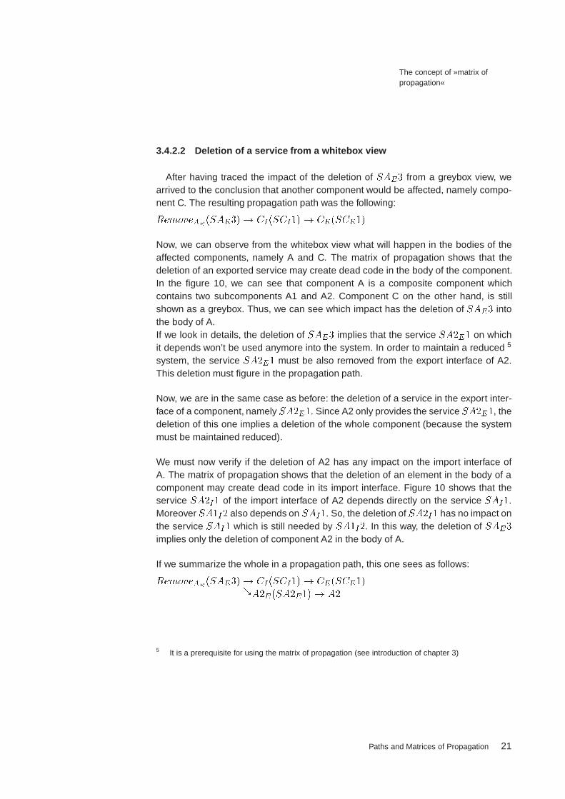
3.4.2.2 Deletion of a service from a whitebox view
After having traced the impact of the deletion of SAE3 from a greybox view, wearrived to the conclusion that another component would be affected, namely compo-nent C. The resulting propagation path was the following:
RemoveAE (SAE3)! CI(SCI1)! CE(SCE1)
Now, we can observe from the whitebox view what will happen in the bodies of theaffected components, namely A and C. The matrix of propagation shows that thedeletion of an exported service may create dead code in the body of the component.In the figure 10, we can see that component A is a composite component whichcontains two subcomponents A1 and A2. Component C on the other hand, is stillshown as a greybox. Thus, we can see which impact has the deletion of SAE3 intothe body of A.If we look in details, the deletion of SAE3 implies that the service SA2E1 on whichit depends won’t be used anymore into the system. In order to maintain a reduced 5
system, the service SA2E1 must be also removed from the export interface of A2.This deletion must figure in the propagation path.
Now, we are in the same case as before: the deletion of a service in the export inter-face of a component, namely SA2E1. Since A2 only provides the serviceSA2E1, thedeletion of this one implies a deletion of the whole component (because the systemmust be maintained reduced).
We must now verify if the deletion of A2 has any impact on the import interface ofA. The matrix of propagation shows that the deletion of an element in the body of acomponent may create dead code in its import interface. Figure 10 shows that theservice SA2I1 of the import interface of A2 depends directly on the service SAI1.Moreover SA1I2 also depends on SAI1. So, the deletion of SA2I1 has no impact onthe service SAI1 which is still needed by SA1I2. In this way, the deletion of SAE3
implies only the deletion of component A2 in the body of A.
If we summarize the whole in a propagation path, this one sees as follows:
RemoveAE (SAE3)! CI(SCI1)! CE(SCE1)&A2E(SA2E1)! A2
5 It is a prerequisite for using the matrix of propagation (see introduction of chapter 3)
Paths and Matrices of Propagation 21

The concept of »matrix ofpropagation«
3.4.3 Modification of a service
The third kind of change we want to trace is the »modification« of a service. The wordmodification is quite abstract, so that the expression »modification of a service« canhave a lot of significations. It can mean for example that the static specification, or thedynamic specification of the service has to be changed.The goal of this paper is first to introduce the matrix of propagation as a methodto trace dependencies in component-based software systems. In this way, we willconsider the notion of »modification« in its global meaning.In the following paragraphs, we will trace the impact of a modification of the serviceSAE1 on the components A, B, C, D and E. We will start with a greybox view of bothcomponents, and then in more details with a whitebox view.
In this paper, we considered that if a given modification of an element has an impacton another element, this impact is a modification or a deletion of the second element(in case of deletion, the deleted element would be replaced by a new one). In thissection, in order to simplify the example, we will consider that the impact of a modi-fication is always modification (for the cases »addition« and »deletion«, see sections3.4.1 and 3.4.2).
3.4.3.1 Modification of a service from a greybox view
From a greybox view, the matrix of propagation shows that the modification of ser-vice in an export interface may have an impact on the import interface of the samecomponent, and has an impact on at least one of its Importer components (since thesystem is reduced, at least one component imports the modified service).Figure 11 shows that one service called SBI1 depends directly on SAE1, and thatSAE1 depends indirectly on the two services SAI1 and SAI2. In this way, if SAE1
is modified, all SBI1, SAI1, SAI2 could be concerned, i.e they could also need amodification. The propagation path of the modification of SAE1 will start with threecases, as follows:
%AI(SAI2)
ModifyAE(SAE1)! AI(SAI1)&BI(SBI1)
The matrix of propagation shows that the modification of service in an import inter-face may have an impact on the export interface of the same component, and has animpact on at least one of its Exporter components (since the system is reduced, themodified service depends on another service which will also have to be modified).Now we must consider the three potential modifications of SBI1, SAI1, SAI2. The
Paths and Matrices of Propagation 22
The concept of »matrix ofpropagation«
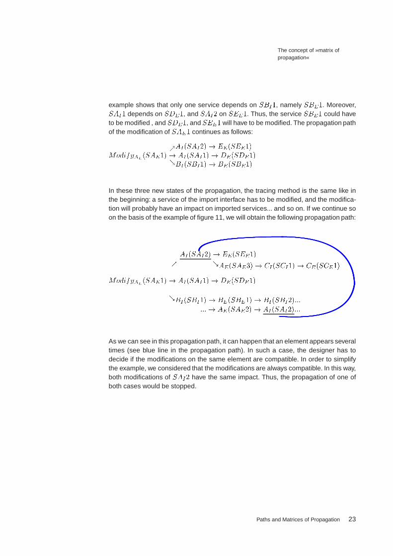
example shows that only one service depends on SBI1, namely SBE1. Moreover,SAI1 depends on SDE1, and SAI2 on SEE1. Thus, the service SBE1 could haveto be modified , and SDE1, and SEE1 will have to be modified. The propagation pathof the modification of SAE1 continues as follows:
%AI(SAI2)! EE(SEE1)
ModifyAE(SAE1)! AI(SAI1)! DE(SDE1)&BI(SBI1)! BE(SBE1)
In these three new states of the propagation, the tracing method is the same like inthe beginning: a service of the import interface has to be modified, and the modifica-tion will probably have an impact on imported services... and so on. If we continue soon the basis of the example of figure 11, we will obtain the following propagation path:
AI(SAI2)! EE(SEE1)% &AE(SAE3)! CI(SCI1)! CE(SCE1)
ModifyAE(SAE1)! AI(SAI1)! DE(SDE1)
&BI(SBI1)! BE(SBE1)! BI(SBI2):::
:::! AE(SAE2)! AI(SAI2):::
As we can see in this propagation path, it can happen that an element appears severaltimes (see blue line in the propagation path). In such a case, the designer has todecide if the modifications on the same element are compatible. In order to simplifythe example, we considered that the modifications are always compatible. In this way,both modifications of SAI2 have the same impact. Thus, the propagation of one ofboth cases would be stopped.
Paths and Matrices of Propagation 23

The concept of »matrix ofpropagation«
3.4.3.2 Modification of a service from a whitebox view
After tracing the impact of the modification of SAE1 from a greybox view, we willgo into more details with a whitebox view of the components.The composition of components was hided in the greybox view. Now, we have torepair the impact of the modification of their imported and exported services on theirbodies. Here, two cases can appear:
1 The propagation path studied from a greybox view shows the direction of the pro-pagation of a modification through indirect dependencies. For example SAE1 !
SAI1 shows that the modification of SAE1 has indirectly an impact on SAI1, orSAI2 ! SAE1 shows that the modification of SAI2 has indirectly an impact onSAE3. This indirect impact shows actually that »something« happens betweenSAE1 and SAI1 (or between SAI2 and SAE3)into the body of A. This »some-thing« will be traced in details from the whitebox view.
2 The propagation path studied from a greybox view also shows standalone servicesof an interface of composite components (the last service of any branch of thepath, e.g. SDE1). The modification of such services must also be traced into thebody of the component.
Let us begin with the modifications hidden by the indirect dependencies of compo-sitional components. For that, we have to repair such dependencies in the propa-gation path of paragraph 3.4.3.1. They are the following: AE(SAE1) ! AI(SAI1),AE(SAE1)! AI(SAI2),AE(SAE2)! AI(SAI2), andAI(SAI2)! AE(SAE3).The matrix of propagation shows that the modification of a service in the export inter-face has necessarily an impact into the body. After seeing figure 10, we can concludethat AE(SAE1) ! A1E(SA1E1). Since A1 is in a greybox view, we can apply thesame rules as in chapter 3.4.3.1, and obtain the following result:
AE(SAE1)! A1E(SA1E1)! A1I(SA1I1)&A1I(SA1I2)
Here, the matrix shows that the modification of an element in the body of a compo-nent may create dead code into the import interface. Thus, with the same example,we will obtain:
AE(SAE1)! A1E(SA1E1)! A1I(SA1I1)! AI(SAI1)&A1I(SA1I2)! AI(SAI2)
If we do the same for the indirect dependency AE(SAE2) ! AI(SAI2), we willhave: AE(SAE2)! A1E(SA1E2)! A1I(SA1I2)! AI(SAI2).
Paths and Matrices of Propagation 24

The concept of »matrix ofpropagation«
We will now study the case of the indirect dependency corresponding toAI(SAI2)!
AE(SAE3). The matrix shows that the modification of a service in the import inter-face of a component has necessarily an impact into its body. Indeed, figure 10 indi-cates that SA2I1 depends directly on SAI2. In this way, we obtain AI(SAI2) !
A2I(SA2I1). Since A2 is in a greybox view, we can apply the same rules as in chap-ter 3.4.3.1. The result is the following:AI(SAI2)! A2I(SA2I1)! A2E(SA2E1)The matrix shows that the modification of an element into the body of a compo-nent has necessarily an impact on its export interface. For the case AI(SAI2) !
AE(SAE3) (which was studied from a greybox), view we will have in a whitebox viewthe following path:
AI(SAI2)! A2I(SA2I1)! A2E(SA2E1)! AE(SAE3)
As a last step, we will trace the impact of modifications of services mentioned at theend of a path (like explained in number 2). In the propagation path from paragraph3.4.3.1, we can find such a service, namely SDE1. If we use the matrix like justbefore, we can see that the modification of this exported service has an impact onthe service SD1E1. Since D1 is in a greybox view, we can adopt the same methodlike in paragraph 3.4.3.1 to find out that the modification of SD1E1 has an impacton SD1I1, and that if SD1I1 is modified, SD2E1 will be also concerned. Moreover,since SDE2 directly depends on SD2E1, the modification of SD2E1 concerns alsoSDE2. The modification of SDE1 will be traced from a whitebox view as follows:
DE(SDE)1! D1E(SD1E)1! D1I(SD1I)1! D2E(SD2E)1! DE(SDE)2
By summarizing the results of paragraph 3.4.3.1 and the results obtained in the aboveparagraphs, we can say that the propagation path of the modification of the serviceSAE1 of the component A is the following:
Paths and Matrices of Propagation 25

The concept of »matrix ofpropagation«
A1I(SA1I2)! AI(SAI2)! EE(SEE1)% &A2I(SA2I1):::
:::! A2E(SA2E1)
:::! AE(SAE3):::
:::! CI(SCI1)
:::! CE(SCE1)
ModifyAE(SAE1):::
:::! A1E(SA1E1) ! A1I(SA1I1)! AI(SAI1):::
:::! DE(SDE1)! D1E(SD1E1):::
:::! D1I(SD1I1)! D2E(SD2E1)
&BI(SBI1)! BE(SBE1)! BI(SBI2):::
:::! AE(SAE2)! A1E(SA1E2):::
:::! A1I(SA1I2)! AI(SAI2):::
Paths and Matrices of Propagation 26

Conclusion
4 Conclusion
The matrix of propagation was introduced to trace the impact on modifications oncomponents. In this paper, various aspects of using the Matrix have been evaluated.However, it has to be taken into consideration that the Matrix of Propagation is in anearly stage of research.
Therefore, efforts must be invested in terms of research in this field in order to de-velop and extend this idea. Since it is out of scope of this paper to investigate allpossible aspects regarding the matrix, some areas can be proposed for future works.For example, the term »modify« in the matrix would be treated in its global meaning.In the future, several aspects of a modification will have to be identified, e.g. seman-tical modification of an element in a component, or modification of the behavior ofa component etc. Additionally, the notion of component properties could be introdu-ced in the future. Properties may be added, deleted, modified, but they can also bestrengthened or weakened. Therefore a new matrix could be developed in order todescribe the impact of the modification of properties in a better way.
After achieving a certain level of maturity, the matrix should be implemented in asoftware tool. This tool will automatically calculate the propagation path of a givenmodification of any component of a system. Thus, it could become a very helpful toolfor any component based software developer.
On the other side the matrix cannot be considered as a universal solution for diagno-sing all the problems arising inside a component based system. For instance, binarycodes inside components have not been considered in this paper. In such cases, thematrix could be combined with tools and techniques which analyze these codes. Cer-tainly more research has to be done in this direction to find out the ways to extendit.
The component model considered in this paper is still under way. Within the scopeof the project »Continuous Software Engineering« [2][3][6], the component specifica-tions of this component model are under research [6]. In this way, the technique ofpropagation matrices as such cannot be actually used at the implementation phaseand after deployment. Future work should adapt this idea for technologies which arecurrently used, e.g. Enterprise Java Beans.
Paths and Matrices of Propagation 27

Bibliography
5 Bibliography
[1] C. Berthomieu: Matrix of propagation - A concept to trace dependencies incomponent-based software systems.Diplomarbeit, Technische Universität Berlin, 2002.
[2] S. Mann, A. Borusan, H. Ehrig, M. Große-Rhode, R. Mackenthun, A. Sünbül, H.Weber: Towards a Component Concept for Continuous Software Engineering.Technischer Bericht 55/00, Fraunhofer ISST, Berlin,2000.
[3] A. Borusan, M. Große-Rhode, H. Ehrig, R-D. Kutsche, S. Mann, J. Padberg,A. Sünbül, H. Weber: Kontinuierliches Engineering: Grundlegende Terminologieund Basiskonzepte.Interner Bericht des Projekts Kontinuierliches Engineering für Evolutionäre IuK-Infrastrukturen, Fraunhofer ISST, 2000.
[4] M. Große-Rhode, R-D. Kutsche, F. Bübl: Concepts for the Evolution ofComponent-Based Software Systems.Technical Report 2000/11, Technische Universität Berlin, Dep. of computerscience, 2000.
[5] F. Bübl: Introducing Context-Based Constraints.In proc.: Fundamental Approaches to Software Engineering (FASE), Grenoble,France, April 2002. Eds.: R. Kutsche, H. Weber.Springer Verlag, Lecture Notes in Computer Science 2306.
[6] U. Kriegel: ComponentML - Eine Markup-Language zur Spezifikation von Kom-ponenten , version 0.6.Interner Bericht des Projekts Continuous Software Engineering, FraunhoferISST, 2000.
[7] S. Comella-Dorda , K. Wallnau, R. C. Seacord, J. Robert: A Survey of LegacySystem Modernization Approaches.Technical Report 2000, Carnegie Mellon University, Software Engineering Insti-tute, 2000.http://www.sei.cmu.edu/publications/documents/00.reports/00tn003.html
[8] N. Weiderman, D. Smith, S. Tilley: Approaches to Legacy System EvolutionTechnical Report 1997, Carnegie Mellon University, Software Engineering Insti-tute, 1997.http://www.sei.cmu.edu/publications/documents/97.reports/97tr014/97tr014abstract.html
Paths and Matrices of Propagation 28

Bibliography
[9] Stanford Encyclopedia of Philosophy, Modal Logic.The metaphysics Research Lab, Center for the Study of Language and Informa-tion, Stanford University.http://plato.stanford.edu/
[10] H. Schumann, M. Goedicke, Component Oriented Software Development with�, paper, 1994.
[11] G.T. Heineman, W.T. Councill: Component-Based Software Engineering, Puttingthe Pieces Together.Addison Wesley, 2001.
[12] P. Herzum, O. Sims: Business Component Factory.OMG Press, Wiley, 2000.
[13] J. Rumbaugh, G. Booch, I. Jacobson: The Unified Modeling Language Refe-rence Manual.Addison Wesley, 1999.
[14] J. Cheesman, J. Daniels: UML Components.Addison Wesley, 2000.
[15] M. Fowler: UML Distilled.Addison Wesley, 1997.
[16] D.F. D’Souza,A.C. Wills: Objects, components, and frameworks with UML, TheCatalysis Approach.Addison Wesley, 1998.
[17] Ed Roman: Mastering Enterprise Java Beans and the Java2 Platform.Wiley, 1999.
[18] R. Burkhadt: UML- Unified Modeling Language, Objektorientierte ModellierungFür die PraxisAddison Wesley, 1997.
[19] C. Szyperski: Component Software - Beyond Object-Oriented Programming.Addison Wesley, 1997.
Paths and Matrices of Propagation 29