patient transfers & stretcher€¦ · patient transfers & stretcher parts breakdown &...
TRANSCRIPT
Patient Transfers
& Stretcher
Parts Breakdown & Assemblies
380748
Revision H – 9/26/16
382000-1, 382000-1L, 383000-1, 383000-1L, 382010-1, 382010-1L, 383010-1, 383010-1L,
382510-X, 383500-1, 382500-1, 383510-X, 384000-1, 385000-1, 386000-1, 387000-1,388000-1,
389000-1, 391000-1, 392000-1, 393000-1, 394000-1,
Note: Add prefix (2- ) when Tan is used
Penner Patient Care 101 Grant Street Aurora, NE 68818
For Service Please Call 1-800-732-0717 or 1-866-736-6377
Visit Our Web Site www.pennerpatientcare.com

2
TRANSFER & STRETCHER PARTS & ASSEMBLIES INDEX
INTRODUCTION: The parts for Transfers are the same with a few variables. The Transfer Chairs and
Bases vary because of the type of tub it is used with. The Chair clamps and covers also vary because of
chair size and scales. There are only two pillars Standard and Bariatric. The Batteries, wall chargers, and
hand controls are the same on all. There are two different controllers, one for Bariatric and one for
standard. Casters and rubber bumpers vary with the type of base, however there is only two sizes of
bumpers and casters are either 3” or 4”, braked and non-braked. The following pages will identify by
model number what is used where.
Contents IDENTIFICAITON OF TRANSFER BASES ........................................................................................................................... 3
CHART BASES, BUMPERS, AND CASTERS ....................................................................................................................... 4
IDENTIFICAITON OF TRANSFER CHAIRS ......................................................................................................................... 5
CHART CHAIRS, ARMS, SEAT, BACK REST, GRIPS, & PADS ............................................................................................... 6
COMPONENTS OF THE OPTIONAL END OPENNING WITH ELITE TRANSFER CHAIR ...................................................... 7
TRANSFER SCALE MOUNTING CLAMP AND ASSEMBLY –BASE AND CASTERS .............................................................. 8
TRANSFER SCALE, BATTERIES, CONTROLLER, HAND CONTROL, CABLES, AND BELTS .................................................. 9
CHART OF COVERS AND CLAMPS ON MODELS ........................................................................................................... 10
TRANSFER CHAIR MOUNTING, VARIOUS ARMS, AND CUSHIONS ............................................................................... 11
SEAT CUSHION WITH HARDWARE, CHAIR LOCK, AND TOILET PAN KIT ...................................................................... 12
STRETCHER LIFT COMPONENTS AND PADS ................................................................................................................. 13
INSTALLING THE SCALE ON A LIFT WITHOUT SCALE.................................................................................................... 14
SCALE CALIBRATION PROCEDURE ............................................................................................................................... 16
TRANSFER MOTOR AND SCALE CARRAIGE ASSEMBLY ................................................................................................ 17
TRANSFER PILLAR, ACTUATOR, AND MOTOR ASSEMBLY ............................................................................................ 18
PILLAR AND ACTUATOR TECHNICAL NOTES .................................................................................................................. 19
INSTRUCTIONS FOR REPLACING THE ACTUATOR ........................................................................................................ 21

3
IDENTIFICAITON OF TRANSFER BASES (Refer to Work Order)
SUPERIOR END
BASE 380050
CASCADE LEFT
BASE 380100L
SUPERIOR LEFT
BASE 380056
CASCADE RIGHT
BASE 380100
SUPERIOR
RIGHT BASE
380055
PACIFIC CHAIR
BASE 393100
END OPENING
BASE 380100E
END OPENING
BASE 380100EL
BARIATRIC LEFT
BASE 380101BL
BARIATRIC
BASE 380101B

4
CHART BASES, BUMPERS, AND CASTERS
MODEL BASE BOOT FRONT
(SMALL)
380345
BOOT REAR
(LARGE)
380350
CASTER 3”
(SMALL)
380355
CASTER 4”
BRAKED
*380360
CASTER 4” NON-
BRAKE 380365
382000-1 380100 3 1 2 2 0
382000-1L 380100L 3 1 2 2 0
382010-1 380100E 0 4 0 2 2
382010-1L 380100EL 0 4 0 2 2
382500-1 380101B 4 1 4 2 0
382510-X 380101B 4 2 4 2 0
383000-1 380100 3 1 2 2 0
383000-1L 380100L 3 1 2 2 0
383010-1L 380100EL 0 4 0 2 2
383500-1 380101B 5 1 4 2 0
383510-X 380101B 5 2 4 2 0
384000-1 380055 0 4 2 2 0
385000-1 380056 0 4 2 2 0
386000-1 380050 2 2 2 2 0
387000-1 380055 0 4 2 2 0
388000-1 380056 0 4 2 2 0
389000-1 380050 2 2 2 2 0
*391000-1 391352 See page
13
See page
13
*392000-1 391352 See page
13
See page
13
393000-1 393100 0 4 0 2 2
394000-1 393100 0 4 0 2 2

5
IDENTIFICAITON OF TRANSFER CHAIRS
(Refer to Work Order)
381150 381140 391150
381145
381150E
• 381150 - Cascade transfer chair frame • 381140 - Superior transfer chair frame • 381145 - Cascade Bariatric chair frame • 391150 - Pacific transfer chair frame • 381150E - Chair frame end opening
NOTE: Refer to your work order Bill of Materials and Functional List FL006
when assembling a Transfer Lift.

6
MODEL CHAIR ARM
381160SER
HAND BAR BACKREST /
ARM
SEAT
PAD
BACK
REST PAD
PUSH
BAR
HAND
GRIP
381108
382000-1 381150 2 381115 381117 381130 4
382000-1L 381150 2 381115 381117 381130 4
382010-1 381150E 391161SER 391160ESER 381117 381130 4
382010-1L 381150E 391161SER 391160ESER 381117 381130 4
382500-1 381145 2 381115 381117 381134 4
382500-1L 381145 2 381115 381117 381134 4
382510-1 381150 2 381115 381117 381134 4
382510-1L 381150 2 381115 381117 381134 4
383000-1 381150 2 381115 381117 381130 4
383000-1L 381150 2 381115 381117 381130 4
383010-1 381150E 391161SER 391160ESER 381117 381130 4
383010-1L 381150E 391161SER 391160ESER 381117 381130 4
383500-1 381145 2 381115 381117 381134 4
383510-1 381150 2 381115 381117 381134 4
384000-1 381140 2 381115 381117 381132 4
385000-1 381140 2 381115 381117 381132 4
386000-1 381140 2 381115 381117 381132 4
387000-1 381140 2 381115 381117 381132 4
388000-1 381140 2 381115 381117 381132 4
389000-1 381140 2 381115 381117 381132 4
391000-1 391363R 2 390765 390760 381132 2
392000-1 391364L 2 390765 390760 381132 2
393000-1 391150 391161SER 391160SER 381115 381117 381132 4
394000-1 391150 391161SER 391160SER 381115 381117 381132 4
CHART CHAIRS, ARMS, SEAT, BACK REST, GRIPS, & PADS
Note: FOR TAN ADD (2) IN FRONT OF NUMBER BELOW

7
COMPONENTS OF THE OPTIONAL END
OPENNING WITH ELITE TRANSFER CHAIR
Chair Variations:
481150-1 Chair complete blue w/o hole
481150-2 Chair complete blue w/hole
481150-3 Chair complete gray w/o hole
481151-1 Chair complete blue w/hole
481151-2 Chair comp brown w/hole
481151-3 Chair comp gray w/hole
Arm Variations:
481160-1 Arm rest R/H blue
481160-2 Arm rest R/H brown
481160-3 Arm rest R/H gray
481161-1 Arm rest L/H blue
481161-2 Arm rest L/H brown
481161-3 Arm rest L/H gray
Chair Mounting Bracket
383195 Chair Mounting Bracket White EO W/Elite
2-383195 Chair Mounting Bracket Tan EO W/Elite
480209 Screw-3/8-16x1 sh cap ultra coat
8
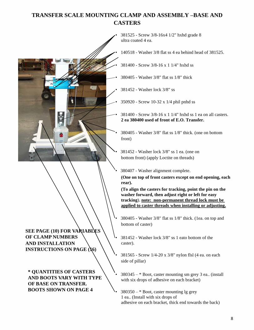
TRANSFER SCALE MOUNTING CLAMP AND ASSEMBLY –BASE AND
CASTERS
SEE PAGE (10) FOR VARIABLES
OF CLAMP NUMBERS
AND INSTALLATION
INSTRUCTIONS ON PAGE (16)
* QUANTITIES OF CASTERS
AND BOOTS VARY WITH TYPE
OF BASE ON TRANSFER.
BOOTS SHOWN ON PAGE 4
• 381525 - Screw 3/8-16x4 1/2" hxhd grade 8
ultra coated 4 ea.
• 140518 - Washer 3/8 flat ss 4 ea behind head of 381525.
• 381400 - Screw 3/8-16 x 1 1/4" hxhd ss
• 380405 - Washer 3/8" flat ss 1/8" thick
• 381452 - Washer lock 3/8" ss
• 350920 - Screw 10-32 x 1/4 phil pnhd ss
• 381400 - Screw 3/8-16 x 1 1/4" hxhd ss 1 ea on all casters.
2 ea 380400 used of front of E.O. Transfer.
• 380405 - Washer 3/8" flat ss 1/8" thick. (one on bottom
front)
• 381452 - Washer lock 3/8" ss 1 ea. (one on
bottom front) (apply Loctite on threads)
• 380407 - Washer alignment complete.
(One on top of front casters except on end opening, each
rear).
(To align the casters for tracking, point the pin on the
washer forward, then adjust right or left for easy
tracking). note: non-permanent thread lock must be
applied to caster threads when installing or adjusting.
• 380405 - Washer 3/8" flat ss 1/8" thick. (1ea. on top and
bottom of caster)
• 381452 - Washer lock 3/8" ss 1 eato bottom of the
caster).
• 381565 - Screw 1/4-20 x 3/8" nylon flsl (4 ea. on each
side of pillar)
• 380345 – * Boot, caster mounting sm grey 3 ea.. (install
with six drops of adhesive on each bracket)
• 380350 – * Boot, caster mounting lg grey
1 ea.. (Install with six drops of
adhesive on each bracket, thick end towards the back)
9
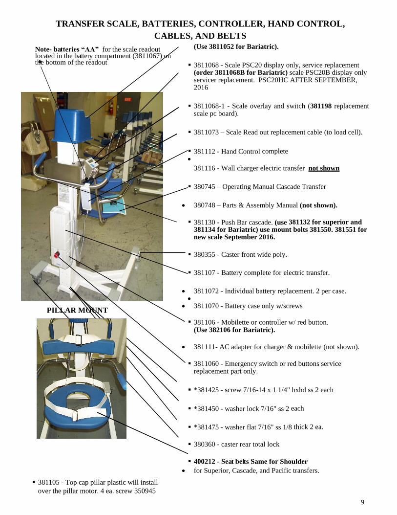
TRANSFER SCALE, BATTERIES, CONTROLLER, HAND CONTROL,
CABLES, AND BELTS
Note- batteries “AA” for the scale readout located in the battery compartment (3811067) on the bottom of the readout
PILLAR MOUNT
381105 - Top cap pillar plastic will install
over the pillar motor. 4 ea. screw 350945
(Use 3811052 for Bariatric).
3811068 - Scale PSC20 display only, service replacement (order 3811068B for Bariatric) scale PSC20B display only servicer replacement. PSC20HC AFTER SEPTEMBER, 2016
3811068-1 - Scale overlay and switch (381198 replacement scale pc board).
3811073 – Scale Read out replacement cable (to load cell).
381112 - Hand Control complete
381116 - Wall charger electric transfer not shown
380745 – Operating Manual Cascade Transfer
380748 – Parts & Assembly Manual (not shown).
381130 - Push Bar cascade. (use 381132 for superior and
381134 for Bariatric) use mount bolts 381550. 381551 for new scale September 2016.
380355 - Caster front wide poly.
381107 - Battery complete for electric transfer.
3811072 - Individual battery replacement. 2 per case.
3811070 - Battery case only w/screws
381106 - Mobilette or controller w/ red button. (Use 382106 for Bariatric).
381111- AC adapter for charger & mobilette (not shown).
3811060 - Emergency switch or red buttons service replacement part only.
*381425 - screw 7/16-14 x 1 1/4" hxhd ss 2 each
*381450 - washer lock 7/16" ss 2 each
*381475 - washer flat 7/16" ss 1/8 thick 2 ea.
380360 - caster rear total lock
400212 - Seat belts Same for Shoulder
for Superior, Cascade, and Pacific transfers.

10
CHART OF COVERS AND CLAMPS ON MODELS
NOTE: For Tan color, add (2-)in front of the indicated number:
TRANSFER LIFT MODEL COVER
FRONT
COVER
BACK
CLAMP
FRONT
CLAMP
BACK
SUPERIOR –384000-1, 385000-1, 386000-1 381189 381184 381175 381180
SUPERIOR W/SCALE - 387000-1, 388000-1, 389000-1 381188 NA 381175 381187
CASCADE - 382000-1, 382000-1L 381183 381184 381175 381180
CASCADE W/SCALE – 383000-1, 383000-1L 381186 NA 381175 381187
CASCADE BARIATRIC – 382500-1 3811832 381184 381175 381180
CASCADE BARIATRIC W/SCALE – 383500-1 3811834 381184 381175 381187
CASCADE STANDARD BARIATRIC – 382510-1 381183 NA 381175 381180
CASCADE ST BARIATRIC W/SCALE – 383510-1 381186 NA 381175 381187
CASCADE END OPENING (EO) – 382010-1, 382010-1L 381183 381184 381175 381180
CASCADE EO W/SCALE – 383010-1, 383010-1L 381186 NA 381175 381187
PACIFIC CHAIR – 393000-1 381189 381184 381175 381180
PACIFIC CHAIR W/SCALE – 394000-1 381188 NA 381175 381187
PACIFIC STRETCHER – 391000-1 391105 NA NA NA
PACIFIC STRETCHER W/SCALE – 392000-1 3811833 NA 381175 381187

11
TRANSFER CHAIR MOUNTING, VARIOUS ARMS, AND CUSHIONS
381500 - Screw 3/8-16 x 1" hx hd 4 ea.
381452 - Washer lock 3/8" ss
391170- Bumper pacific chair transfer only.
380403 - Screws 1/4-20
381550 - Screw 1/4-20 x 1 1/2 grd 8
ultra coated(Push Bar mounting screws two ea) After
September 2016 use 381551- Screw 5/16-18 x 1 ¾”
381113 - Screw 1/4-20 x 1 3/4" bhsh ss 2 ea.
381109 - Strap bushing 2 ea.
381110 - Bushing concave 2 Ea. on each push bar
and 2 ea. used on each back rest except on Pacific,
EO, and Bariatrics.
381117 - Backrest transfer blue.
2-381117 for Tan
*381160SER - Arm - transfer 2 ea. (Includes arm
end plug and black only grip). Arm end plug, order
separately381161.
2-381108 - Hand grips black only.
381186 - Cover clamp cascade scale.
(Determined on page 10)
381172 - Pin dowel arm lock
*Note: (use 391160SER for Pacific back rest , arm &
391161SER for Pacific hand bar arm). (Use 391161SER
arm and 391160SER backrest on the End Opening). Arms
come with end plug and hand grips (Black only)
PACIFIC
CHAIR
ONLY

12
SEAT CUSHION WITH HARDWARE, CHAIR LOCK, AND TOILET PAN KIT
EXPLODED VIEW BELOW
400306- Center Strap
Note: Center strap attached on pacific and End Opening chairs only on the seat. (Screw length ground down flush with top side). Apply Loctite to threads.
381115 - Seat complete blue 2-381115 - Seat complete tan Both include below: 390127 -Spacer (washer) 3 ea for seat bolt 3811201 • 3811201 - Bolt seat post 3 ea.
• 381193 - Screw shldr 1/4" dia 1/2" lng • 381192 - Spring - seat lock • 381191 - Plate - seat lock
• 381324 - Optional toilet pan kit for patient transfers.
381324EO- Optional toilet pan kit for patient End Opening and Pacific chair transfers.
• 381332 – Toilet bowl
Pacific & EO chair seat complete
391115 - Blue
2-391115 - Tan.
(Includes parts below):
381115B - Seat only blue (38115T Seat only tan)
400600 - Screw 1/4-20 x 3/4 hxhd ss
390129 - Washer 1/4 star external ss
391166 - Hook- seat pad pacific
390127 - Spacer 3/4od x 1/4id 1/8 thkss
380402 - Screw 1/4-20 x 3/4" phfthd ss
400306 - Center belt and bracket
EXPLODED
VIEW
BELOW

13
STRETCHER LIFT COMPONENTS AND PADS
391357 – Safety strap button–arm,(in
back of arm)
390653 – Safety Belt – stretcher
391365 – Stretcher wing lock
391359 – Lock indicator cover white-right
391358 – Lock indicator cover white-left
390753 – Pillow
391362 – Aluminum knob
391356 –Safety strap button
Wing (mount screw-391349)
400615 - Bumper guard
2-381108 – Hand grips (black only)
391367 – Handle no scale
391353 – Arm assembly
391364 – Wing-left
390760 – Pad large
390765 – Pad small
391351 – Outside tube
391350 – Inside tube (not shown)
391352 – Lift base
391363 – Wing-right
390757 –Leg protector
381104 – Actuator (not shown)
380355 – Caster 3” non-lock
391354 – Steering lock stop
391368 - Steering lock
391360 – Caster 4” lock
14
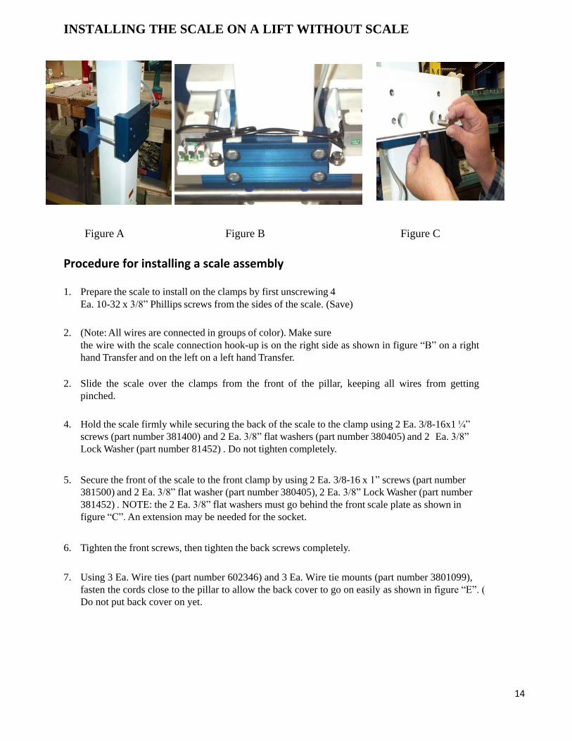
INSTALLING THE SCALE ON A LIFT WITHOUT SCALE
Figure A Figure B Figure C
Procedure for installing a scale assembly
1. Prepare the scale to install on the clamps by first unscrewing 4
Ea. 10-32 x 3/8” Phillips screws from the sides of the scale. (Save)
2. (Note: All wires are connected in groups of color). Make sure
the wire with the scale connection hook-up is on the right side as shown in figure “B” on a right
hand Transfer and on the left on a left hand Transfer.
2. Slide the scale over the clamps from the front of the pillar, keeping all wires from getting
pinched.
4. Hold the scale firmly while securing the back of the scale to the clamp using 2 Ea. 3/8-16x1 ¼”
screws (part number 381400) and 2 Ea. 3/8” flat washers (part number 380405) and 2 Ea. 3/8”
Lock Washer (part number 81452) . Do not tighten completely.
5. Secure the front of the scale to the front clamp by using 2 Ea. 3/8-16 x 1” screws (part number
381500) and 2 Ea. 3/8” flat washer (part number 380405), 2 Ea. 3/8” Lock Washer (part number
381452) . NOTE: the 2 Ea. 3/8” flat washers must go behind the front scale plate as shown in
figure “C”. An extension may be needed for the socket.
6. Tighten the front screws, then tighten the back screws completely.
7. Using 3 Ea. Wire ties (part number 602346) and 3 Ea. Wire tie mounts (part number 3801099),
fasten the cords close to the pillar to allow the back cover to go on easily as shown in figure “E”. (
Do not put back cover on yet.
15
Figure G
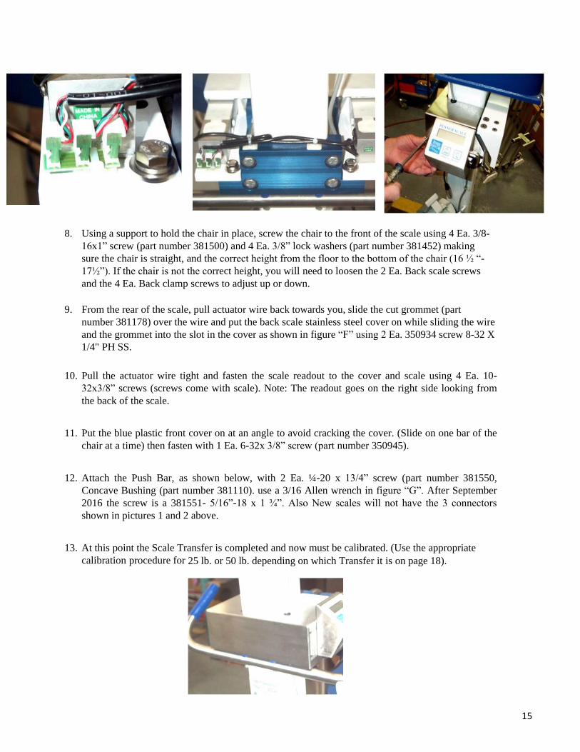
8. Using a support to hold the chair in place, screw the chair to the front of the scale using 4 Ea. 3/8-
16x1” screw (part number 381500) and 4 Ea. 3/8” lock washers (part number 381452) making
sure the chair is straight, and the correct height from the floor to the bottom of the chair (16 ½ “-
17½”). If the chair is not the correct height, you will need to loosen the 2 Ea. Back scale screws
and the 4 Ea. Back clamp screws to adjust up or down.
9. From the rear of the scale, pull actuator wire back towards you, slide the cut grommet (part
number 381178) over the wire and put the back scale stainless steel cover on while sliding the wire
and the grommet into the slot in the cover as shown in figure “F” using 2 Ea. 350934 screw 8-32 X
1/4" PH SS.
10. Pull the actuator wire tight and fasten the scale readout to the cover and scale using 4 Ea. 10-
32x3/8” screws (screws come with scale). Note: The readout goes on the right side looking from
the back of the scale.
11. Put the blue plastic front cover on at an angle to avoid cracking the cover. (Slide on one bar of the
chair at a time) then fasten with 1 Ea. 6-32x 3/8” screw (part number 350945).
12. Attach the Push Bar, as shown below, with 2 Ea. ¼-20 x 13/4” screw (part number 381550,
Concave Bushing (part number 381110). use a 3/16 Allen wrench in figure “G”. After September
2016 the screw is a 381551- 5/16”-18 x 1 ¾”. Also New scales will not have the 3 connectors
shown in pictures 1 and 2 above.
13. At this point the Scale Transfer is completed and now must be calibrated. (Use the appropriate
calibration procedure for 25 lb. or 50 lb. depending on which Transfer it is on page 18).
16
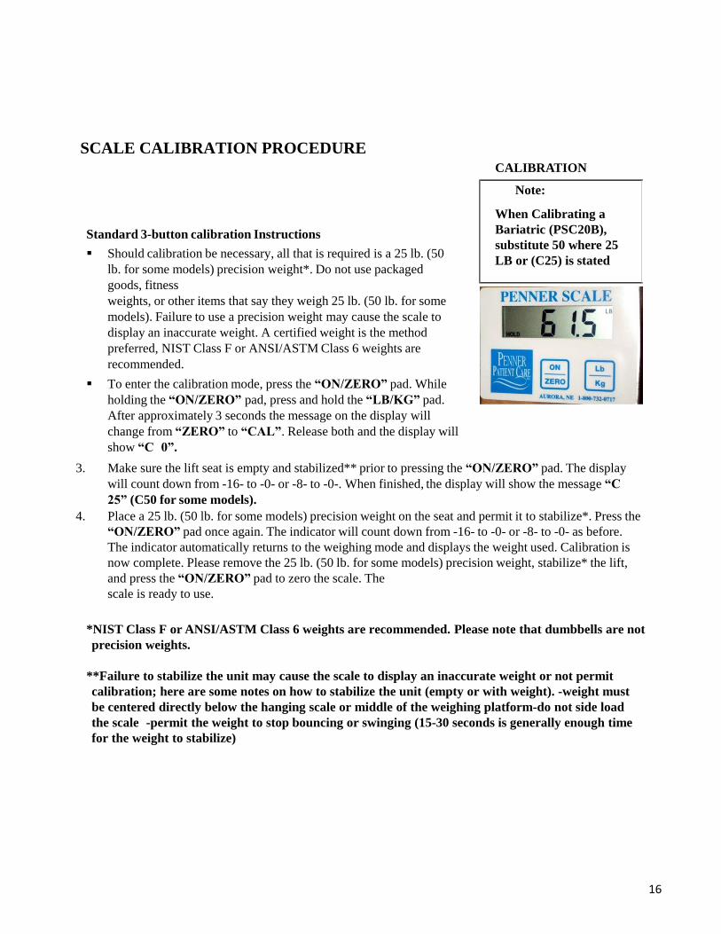
SCALE CALIBRATION PROCEDURE
Standard 3-button calibration Instructions
Should calibration be necessary, all that is required is a 25 lb. (50
lb. for some models) precision weight*. Do not use packaged
goods, fitness
weights, or other items that say they weigh 25 lb. (50 lb. for some
models). Failure to use a precision weight may cause the scale to
display an inaccurate weight. A certified weight is the method
preferred, NIST Class F or ANSI/ASTM Class 6 weights are
recommended.
To enter the calibration mode, press the “ON/ZERO” pad. While
holding the “ON/ZERO” pad, press and hold the “LB/KG” pad.
After approximately 3 seconds the message on the display will
change from “ZERO” to “CAL”. Release both and the display will
show “C 0”.
CALIBRATION
Note:
When Calibrating a
Bariatric (PSC20B),
substitute 50 where 25
LB or (C25) is stated
3. Make sure the lift seat is empty and stabilized** prior to pressing the “ON/ZERO” pad. The display
will count down from -16- to -0- or -8- to -0-. When finished, the display will show the message “C
25” (C50 for some models).
4. Place a 25 lb. (50 lb. for some models) precision weight on the seat and permit it to stabilize*. Press the
“ON/ZERO” pad once again. The indicator will count down from -16- to -0- or -8- to -0- as before.
The indicator automatically returns to the weighing mode and displays the weight used. Calibration is
now complete. Please remove the 25 lb. (50 lb. for some models) precision weight, stabilize* the lift,
and press the “ON/ZERO” pad to zero the scale. The
scale is ready to use. *NIST Class F or ANSI/ASTM Class 6 weights are recommended. Please note that dumbbells are not
precision weights.
**Failure to stabilize the unit may cause the scale to display an inaccurate weight or not permit
calibration; here are some notes on how to stabilize the unit (empty or with weight). -weight must
be centered directly below the hanging scale or middle of the weighing platform-do not side load
the scale -permit the weight to stop bouncing or swinging (15-30 seconds is generally enough time
for the weight to stabilize)

17
TRANSFER MOTOR AND SCALE CARRAIGE ASSEMBLY
380401 – Nut 3/8 x 16 hx ss 18-8 Nylock
380422 -Screw 3/8 x 16 x 1 1/2"hxhd ss
5 1/2” - Distance to locate clamp placement.
(This distance is 5” on stretchers with scales)
381500 -Screw 3/8-16 x 1" hx hd grd 8
380405 - Washer 3/8" flat ss 1/8" thick
381452 - Washer lock 3/8" ss
380401 - Nut 3/8 x 16 hx ss 18-8 nylock
380422 -Screw 3/8 x 16 x 1 1/2“ hxhd ss. 3 ea.
3811075 - Replacement actuator cord & jack
(cut to desired length)
The readout mounting location determined by model
number if left or right transfer.
See page 15 section 9 for installing the stainless steel
cover and readout.
350934 - Screw 8-32 x 1/4" ph pnhd ss
Note: the complete scale PSC20B for the
bariatric is similar just larger.

18
TRANSFER PILLAR, ACTUATOR, AND MOTOR ASSEMBLY
• 381099 - Pillar bearing electric transfer 4 ea.
slides into and out of outside pillar.
• 381565 - Screw 1/4-20 x 1/2" nylon flsl 4 ea.
per side
• *381119 - Pin bottom actuator mount.
• 381123 – Spacer white plastic 2ea. inside on
each side of the actuator mount. must be flush
with surface. (not required on baritatric
pillar).
• **381122 - actuator 600mm long with motor
(382122 – actuator for bariatric). also
requires actuator extension 3821221). order
381104 for replacement actuator on
stretchers)
• 381103 - brkt motor transfer pillar. (381103b
for bariatric)
• 380401 – nut 3/8 x 16 hx ss 18-8
nylock 2 ea.
• 380422 -screw 3/8 x 16 x 1 1/2"hxhd ss 3 ea.
• 381118 - spacer actuator pin top location of no
load switch * see page 19 for technical notes on actuator
replacement
** see page 20 & 21 for technecal notes on motor
disconnect from actuator
19
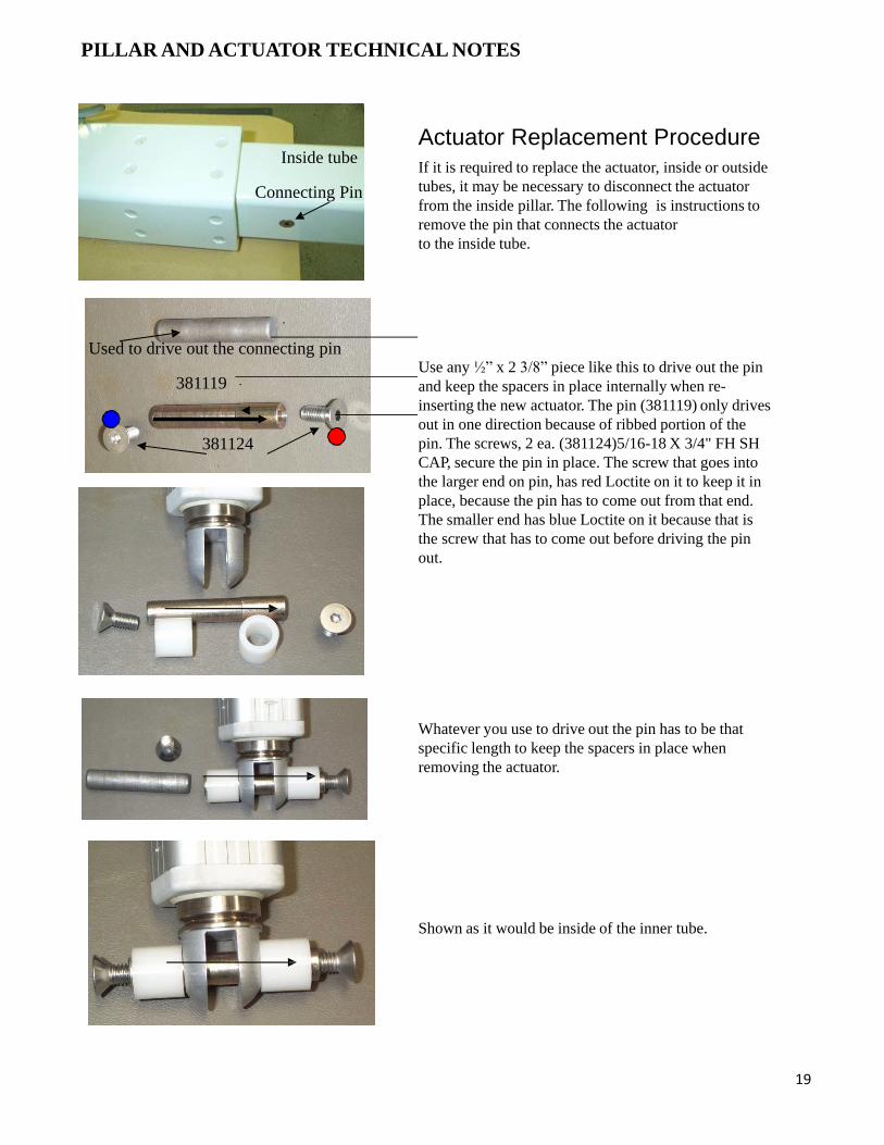
PILLAR AND ACTUATOR TECHNICAL NOTES
Inside tube
Connecting Pin
Used to drive out the connecting pin
381119
381124
Actuator Replacement Procedure
If it is required to replace the actuator, inside or outside
tubes, it may be necessary to disconnect the actuator
from the inside pillar. The following is instructions to
remove the pin that connects the actuator
to the inside tube. Use any ½” x 2 3/8” piece like this to drive out the pin
and keep the spacers in place internally when re-
inserting the new actuator. The pin (381119) only drives
out in one direction because of ribbed portion of the
pin. The screws, 2 ea. (381124)5/16-18 X 3/4" FH SH
CAP, secure the pin in place. The screw that goes into
the larger end on pin, has red Loctite on it to keep it in
place, because the pin has to come out from that end.
The smaller end has blue Loctite on it because that is
the screw that has to come out before driving the pin
out.
Whatever you use to drive out the pin has to be that
specific length to keep the spacers in place when
removing the actuator.
Shown as it would be inside of the inner tube.
21
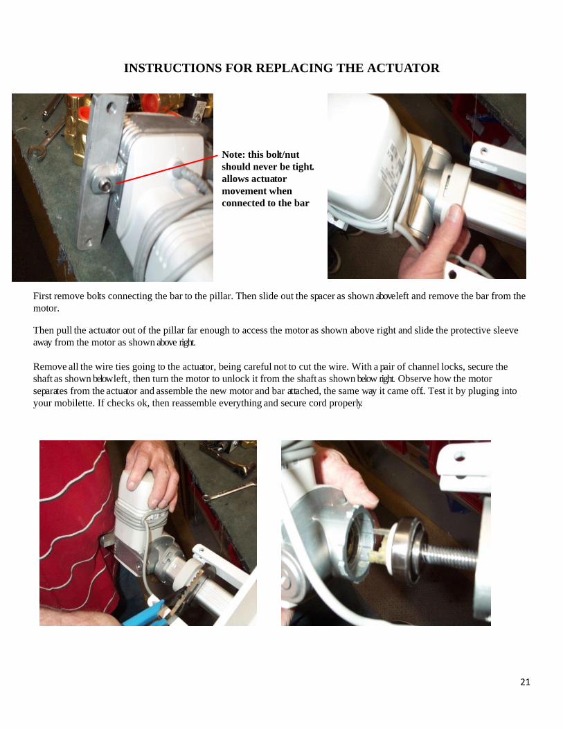
INSTRUCTIONS FOR REPLACING THE ACTUATOR
Note: this bolt/nut
should never be tight.
allows actuator
movement when
connected to the bar
First remove bolts connecting the bar to the pillar. Then slide out the spacer as shown above left and remove the bar from the
motor. Then pull the actuator out of the pillar far enough to access the motor as shown above right and slide the protective sleeve
away from the motor as shown above right.
Remove all the wire ties going to the actuator, being careful not to cut the wire. With a pair of channel locks, secure the
shaft as shown below left., then turn the motor to unlock it from the shaft as shown below right. Observe how the motor
separates from the actuator and assemble the new motor and bar attached, the same way it came off. . Test it by pluging into
your mobilette. If checks ok, then reassemble everything and secure cord properly.