pavement prior to asphal..(u) rmy crckng nd seting of
TRANSCRIPT

no-RI69 532 CRCKNG ND SETING OF PORTLND CEMENT CONCRETE 1/1PAVEMENT PRIOR TO ASPHAL..(U) RMY ENGINEER NATERWAYSEXPERIMENT STATION VICKSBURG MS GEOTE. L N GODWIN
UCRSIIDJAN 86 WES/MP/GL-6- F/0 13/3 N

-~v 7,' ~ N '~A~D..- T,&A - x
iIII
I1.1 2-
-:IIII IIII1Itml
13.5.
'-'.
1"8
,"6
................................................................

MISCELLANEOUS PAPER GL-86-3
mlCRACKING AND SEATING OF PORTLANDArm Cop CEMENT CONCRETE PAVEMENT PRIOR TO
EngieersASPHALT CONCRETE OVERLAY; FACILITIESN TECHNOLOGY APPLICATION TEST, FY 84
(V) by
Lenford N. Godwin
Geotechnical Laboratory
DEPARTMENT OF THE ARMYWaterways Experiment Station. Corps of Ergireers
P0 Box 631, Vicksburg, Mississippi 39180 -063 1IZIVI
DITIC
- N
Janar 19861
Fina Prepfort
aved o nlc es DC i 2031-100
%, .
%*.
Unclassified %SECURITY CLASSIFICATION OF THIS PAOE 'Won aet, F'ored) .. %
READ INSTRUCTIONS '- '" %
REPORT DOCUMENTATION PAGE HflEI-ORE (OMPI.ETN, FORMI REPORT NUMBER 2. GOVT AC ql( N Pi UEME
Miscellaneous Paper GL-86-3 A D 4|____________,__4. TITLE (I'd Subtitle) TYPE OF REPORT & PERIOD COVERED
CRACKING AND SEATING OF PORTLAND CEMENT CONCRETE Final report %,PAVEMENT PRIOR TO ASPHALT CONCRETE OVERLAY; FACIL- FO or6 PERFORMING ORG. REPORT NUM~iER 1
ITIES TECHNOLOGY APPLICATION TEST, FY 847. AUTHOR(.) 8 CONTRACT OR GRANT NUMBER(o)
Lenford N. Godwin
9 PERFORMING ORGANIZATION NAME AND ADDRESS 10. PROGRAM ELEMENT, PROJECT, TASK
US Army Engineer Waterways Experiment Station AREA & WORK UNIT NUMBERS
Geotechnical Laboratory Facilities TechnologyP0 Box 631, Vicksburg, Mississippi 39180-0631 Application Test ProgramIt CONTROLLING OFFICE NAME AND ADDRESS 12. REPORT DATE
DEPARTMENT OF THE ARMY January 1986US Army Corps of Engineers 13 NUMBER OF PAGES - "'"
Washington, DC 20314-1000 -114 MONITORING AGENCY NAME & ADDRESS(If different from Controlling Office) IS SECURITY CLASS. (of thi reporl) .
Unclassified,s., DECLASSIFICAT,0N DOWNGRADING p
SCHEDULE '~ #*
16 DGSTRIBIJTION STATEMENT (of thli Report) b. J
Approved for public release; distribution unlimited.
17 DISTRiBUTION STATEMENT (of the btract etlered In Block 20. If different from Report)
• .N
IS SUPPLEMENTARY NOTES
Available from National Technical Information Service, 5285 Port Royal Road, F
ipr1?.:Mf) i .q Virginia 22161.
19 KEY WORDS (Continuoe on reverse side If nece.eary md Identify by block n-ber)
Pavements, Asphalt concrete--Cracking (LC)Pavements, Concrete -Maintenance and repair (LC)Concrete--Cracking (LC)
,Concrete coatings. (LC)
20 A&STRACT (ConeIf. r.ewr. e . If Z o * eee a idenIlf, by block nht,.b*r)
'Asphalt concrete overlays of a jointed or cracked portland cement con-crete (PCC) pavement can deve!)p reflective cracking because of either hori-.zontal or vertical movement of the PCC. One method that can be used to -educe . ..
the reflect've cracking is cracking and seating of the PCC prior to placement -of the asphalt concrete overlay. The PCC is cracked into approximattly 18-in. .
pieces, after which a heavy pneumatic-tired roller is used to seat the pieces ,
(Cont inued)
DD , 0 3 1473 EDTIONOr IOSSISOSSOLTI Unclassified
SE-CURti'Y Ck ASSIj'IC ATIN 001t T 1% PA ,F. IN '.'. ,tt
C. ~. . . . . .. . - .** e..-.... .'. - . ..2.. S.i-

UnclassifiedSECURITY CLASSIFICATION C'OF THIS PAOlE(I'ho Dts B n9e0.d)
20. ABSTRACT (Continued).
- ) f of concrete to prevent rocking or movement under traffic. This report pro-vides guidance for the application of the cracking and seating method for
reducing reflective cracking.
%?
'V
.
Unclass if ledSECURITY CLASSIFICATION OF THIS PAGF(*h. DlO(* FW-r,d)
PREFACE
This study was sponsored by the Office, Chief of Engineers (OCE), US
Army, as a part of the O&MA Program, Facilities Technology Application Tests
(FTAT), Demonstration Program FY 84 , and was conducted in the Geotechnical
Laboratory (GL) of the US Army Engineer Waterways Experiment Station (WES).
The project was conducted under the general supervision of Dr. W. F.
Marcuson III, Chief, GL; and under the direct supervision of Mr. H. H.
Ulery, Jr., Chief, Pavement Systems Division (PSD); Mr. J. W. Hall, Jr., Chief,
Engineering Investigation Testing, and Validation Group, PSD; and Dr. E. R.
Brown, Chief, Material Research Center, PSD. The WES FTAT Project manager was
MAJ R. A. Hass. Photographic support was provided by Mr. C. E. Ray of the
Publications and Graphic Arts Division. Construction support was provided by
Mr. C. Swynenberg of the Rock Island Facilities Engineering Office. This
report was prepared by Mr. Lenford N. Godwin, PSD. ".
The Asphalt Institute is gratefully acknowledged for permission to
reproaace Photos 3 and 4 of this report.
Director of WES was COL Allen F. Grum, USA. Technical Director was
Dr. Robert W. Whalin.
If further information on this study is desired, you may contact the
following:
OCE Representative
HQDADAEN-ZCF-B (Mr. Robert Williams)Washington, DC 20314.Phone: FTS - 272-0597 . -
AUTOVON - 285-0597 t. c ..
WES Principal Investigator . -Lenford N. Godwin ' - --
WESGP-IMPO Box 631Vicksburg, MS 39180-0631 ""-."Phone: (601)6 34-2 144/ ,', -. I
. . .'-'-

*- - -. - , L. .. -, -. .
CONTENTS
* Page
PREFACE ................................................................ 1
CONVERSION FACTORS, NON-SI TO SI (METRIC) UNITS OF MEASUREMENTS ........ 3
PART I: INTRODUCTION ................................................. 4
History .......................................................... 4Purpose of Report ................................................ 5
PART II: IMPLEMENTING THE METHOD ..................................... 6
Cracking Equipment ............................................... 6Construction Techniques .......................................... 6
PART III: ECONOMICS ..................................... .............. 10
PART IV: ADVANTAGES AND DISADVANTAGES ................................ 11
Advantages.......................................................11
Disadvantages .................................................... 11
* PART V: DEMONSTRATION OF METHOD ..................................... 12
PART VI: RECOMMENDED GUIDANCE ........................................ 13
PCC Pavement Cracking ............................................ 13Test Section ..................................... ................ 13PCC Pavement Seating ............................................. 13Repair ........................................................... 14
PART VII: CONCLUSIONS ..................................... ............ 15
REFERENCES ............................................................. 16
PHOTOS 1-25
2I,'-
°..J.

CONVERSION FACTORS, NON-SI TO SI (METRIC) UNITS OF MEASUREMENT
Non-SI units of measurement used in this report can be converted to SI
(metric) units as follows:
Multiply By To Obtain 4
British thermal units 1,05~4 joules
feet 0.30418 metres
inches 2.54 centimetres
pounds (force) per 6.8924757 kilopascalssquare inch
pounds (mass) 0.245359241 kilograms
square yards 0.83612741 square metres
3. V.,

CRACKING AND SEATING OF PORTLAND CEMENT CONCRETE PAVEMENT
PRIOR TO ASPHALT CONCRETE OVERLAY; FACILITIES
TECHNOLOGY APPLICATION TEST. FY 84
PART I: INTRODUCTION
History
1. Reflective cracking can occur in asphalt concrete overlays of either
jointed portland cement concrete (PCC) or cracked asphalt concrete pavements,
as shown in Photo 1. The reflective cracking is the result of either horizon-
tal or vertical movement of the underlying pavement. The horizontal movement
is caused by temperature or moisture changes in the pavement structure. The
vertical movement is caused by traffic. Both types of movements can induce
high stresses in the asphalt concrete. If the stresses exceed the strength of
- the asphalt concrete, a reflective crack develops.
2. Reflective cracks can result in early deterioration of a pavement
structure, as shown in Photo 2. The deterioration is usually in the form of
spalling and ravelling. Water can enter unsealed cracks and reduce the
strength of the pavement structure. Such early deterioration will require
additional maintenance or replacement of the cracked pavement. The main-
tenance costs resulting from reflective cracking can be very great.
3. Currently several methods are used to reduce the potential for re-
flective cracking. One method involves placing either an asphalt-rubber or a
fabric interlayer over a cracked pavement prior to placement of the asphalt
concrete overlay (Vedros 1981). Another method involves cracking the existing
PCC and then seating the pieces of pavement prior to overlaying with asphalt
concrete.
4. Th2 cracking and seating method has the potential for being more
effective for PCC pavement overlays than asphalt-rubber or fabric interlayer
methods.
5. The cracking and seating method is not new and recent equipment
developments and improvements have encouraged the use of this method. The
objective of the cracking and seating method is to crack the existing PCC
pavement into small, interlocking pieces and then seat the pieces of pavement
4
.'.-
•.....*. . .- . . . . ... .. ". .... -... ..... .--. . - ,.-- . .-* ." .. - .. *- .. . . . -- - . - - . - - 1 1. ' - ' , , " . ,
with a heavy pneumatic-tired roller prior to placing the asphalt concrete
overlay. The cracked pavement should have aggregate-to-aggregate particle
contact; thus, a portion of the original pavement strength is maintained. The
seating with the heavy pneumatic-tired roller prevents any rocking or movement
*of the small pieces when subjected to traffic. By cracking the pavement into
small pieces, the amount of expansion and contraction due to temperature
changes is reduced, which, in turn, should reduce the potential for reflective
cracking.
Purpose of Report
6. This report provides guidance for use of the cracking and seatingmethod for reducing reflective cracking in asphalt concrete overlays of PCC
pavement.
5.
5:
7 V.
PART II: IMPLEMENTING THE METHOD
7. The cracking and seating method requires that certain equipment be
used and certain procedures be followed to produce satisfactory results.
General guidance for equipment and techniques is given in the following w
paragraphs.
Cracking Equipment
8. A variety of types of equipment can be used for the cracking of a
PCC pavement including modified pile-driver hammers, falling-weight hammers
(such as the Guillotine hammer), and hydraulic or pneumatic impact hammers
(Crawford 1984, Eckrose, Poston, Donohue and Associates 1983, Highway and
Heavy Construction 1984, Paving Forum 1984, Sherman 1982, The Asphalt In-
stitute 1984). Photos 3-6 show some of the currently available cracking
equipment. Regardless of the particular names or types, the hammers used to
crack PCC pavement must provide a method for adjusting the impact force de-
livered to the pavement so that the cracking pattern can be varied to suit
field conditions and pavement strength characteristics. The impact force is
usually adjusted by changing the rate of impact, stroke height, forward speed,
or impact head size and shape.
9. The hammer should produce small hairline-type cracks that extend
through the full thickness of the PCC (Photo 7). The cracks must also be
narrow enough to provide for aggregate particle interlock between the cracked
pieces of pavement so that a portion of the pavement strength can be retained.
Equipment or techniques that incorporate the use of chisel-shaped impact
heads, gravity balls, or excessive energy will produce a rubble, as shown in
Photo 8, which will result in the loss of the pavement's structural strength
(Paving Forum 1984). Therefore, equipment or cracking techniques that produce
rubble are not desirable.
Construction Techniques
Pavement preparation
10. Prior to cracking and seating, the existing PCC pavement must be
prepared by cleaning the joints and cracks and by providing good drainage for
6

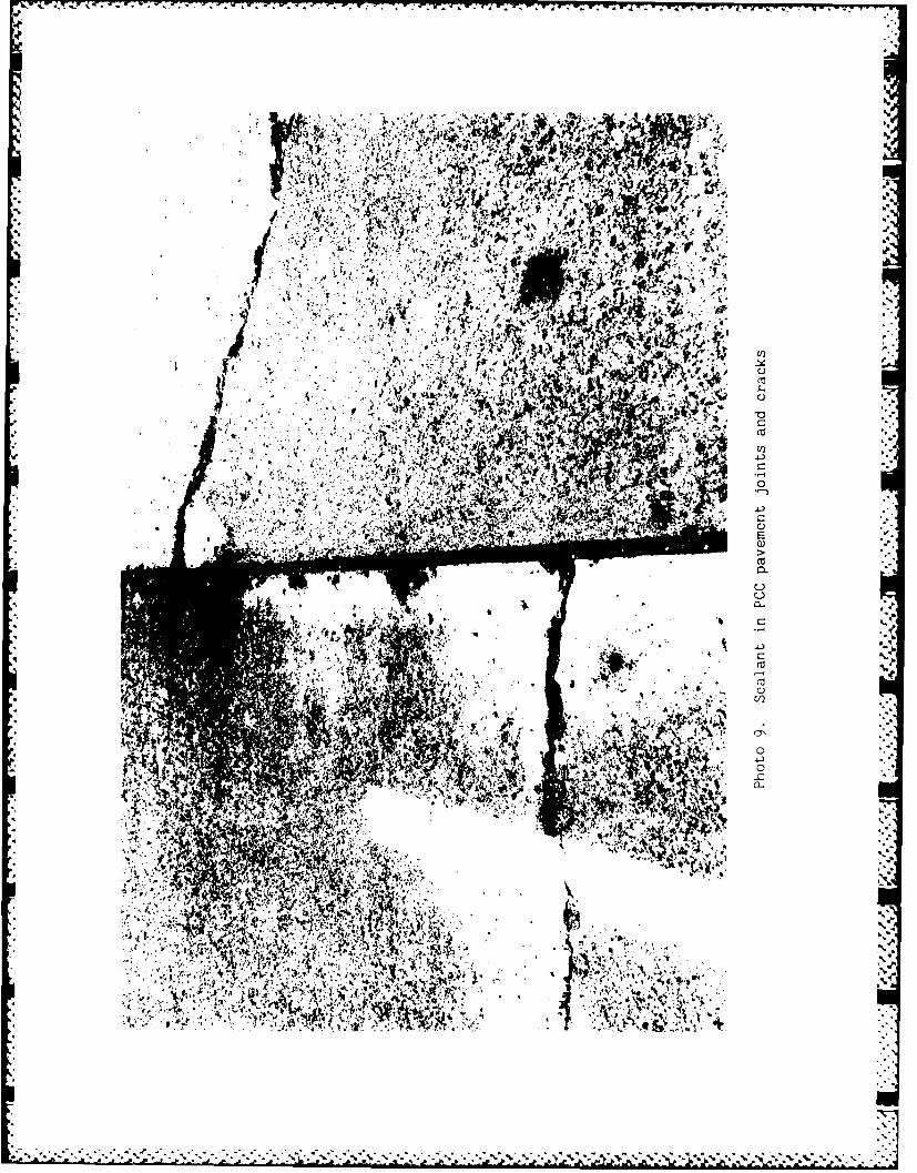
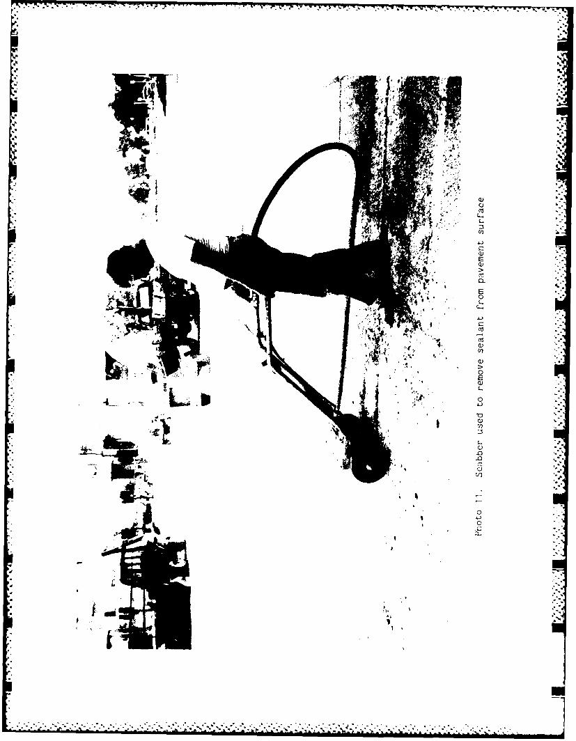
the pavement structure. Joint and crack sealing material, as shown in
Photo 9, should be removed from the pavement surface and from the top 1/2 to
1 in.* of all joints and cracks. Failure to remove this sealant can lead to
pavement slippage or bleeding of the sealant through the hot asphalt concrete
that will be placed later. The sealant in the joints and cracks ca be re-
moved by routing (Photo 10). The sealant on the pavement surface can be A
removed by heating and scraping or by using a scabber, as shown in Photos 11
and 12. In addition to the sealants, any active cold patches should be re-
moved and replaced with hot asphalt concrete prior to overlaying the PCC.
11. Providing adequate drainage (Photo 13) prior to cracking the PCC is
important. Otherwise structural support will be lost which will lead to rock-
ing of the cracked PCC pieces, resulting in a cracked asphalt concrete overlay.
12. In some cases, it may be necessary to install edge drains to pre-
vent water from accumulating under the PCC pieces (Crawford 1984, Paving Forum
1984, The Asphalt Institute 1984).
Cracking procedures and requirements
13. As discussed previously, the cracking and seating method is in-
tended to produce small pieces of PCC pavement that have interlocking capacity
(Photo 14). The cracking pattern that is produced is dependent on several
factors such as the (a) size and shape of the head of the hammer used to crack
the pavement, (b) energy or impact force of the cracking equipment, (c) spac-
ing of the points of contact, (d) strength of the PCC, and (e) strength and
moisture condition of the subgrade.
14. Because there are so many variables that influence the size of the
cracking pattern, it is recommended that prior to the full-scale cracking a
trial section be used to determine the loading conditions that will produce
the desired cracking pattern. This trial section, which should be at least
100 ft long, will allow a contractor an opportunity to develop a satisfactory
cracking pattern for the existing field conditions. The intent of cracking is
not to reduce the PCC to a rubble, but rather to crack the concrete full depth
and into pieces that are 1-1/2 to 3 ft in size (Crawford 1984). This crack
pattern will reduce reflective cracks in the asphalt concrete overlay wh'ch
normally result from excessive stresses caused by, or from, rocking of slabs
* table of factors for converting non-SI units of measurement to SI
(metric) units is presented on page 3.
7

Idunder loads. Breaking the PCC into pieces that are 12 in. or less may result
in pavement spalling and loss of structural strength.
15. When the proper equipment and techniques are used, the cracks that
are produced should be very small or hairline. These cracks are nor normally
visible to the eye unless the surface has been sprayed with water to make the
cracks stand out (Photos 15 and 16). The cracked pieces of pavement must
remain in contact to allow load transfer between the aggregate particles--
otherwise the structural strength of the pavement will be reduced.
16. When cracking the pavement, continuous longitudinal cracks must be
avoided because this type of crack tends to reflect through an overlay. Any
cracking method that produces continuous longitudinal cracks must be adjusted
to eliminate the continuous longitudinal crack.
17. During the course of cracking a pavement, the cracking technique
developed in the trial section will have to be adjusted to suit the various
field conditions such as a wet subgrade and changing concrete strength.
Cracking should not be attempted next to a joint as this could spall the pave-
ment. In addition, cracking should not be attempted over culverts or utility
ducts as these structures could be damaged. Areas with culverts and ducts
should be identified prior to cracking operations.
Seating procedures and requirements
18. Once the PCC has been cracked to the desired size, a heavy
pneumatic-tired roller, such as that shown in Photo 17, should be used to seat
the concrete pieces to prevent slab rocking. This heavy pneumatic roller is
sometimes referred to as a proof roller. The roller should be loaded with
25,000 lb per tire.
19. In general, at least two passes of the heavy pneumatic-tired roller
are required to seat the cracked PCC pavement on roads and streets, while as
many as thirty passes have been used to seat the concrete on heavy-duty air-
fields. Field conditions may vary and influence the seating operation. For
example, if the subgrade is extremely wet or weak, an excess rolling effort
could result in the spalling or breaking of the PCC or nonuniform or excessive
movement of the pavement (Crawford 1984; Eckrose, Poston, Donohue and Asso-
ciates 1983). Therefore, the seating operation must be adjusted to suit field
conditions, but in most cases (on roads and streets) at least two passes of
the roller should be applied to seat the PCC pieces. Wet subgrades should be
provided drainage prior to seating to reduce the possibility of rocking of the
8
Im

concrete pieces or of losing structural support.
Repairs
20. During the cracking procedures, there may be areas where the
cracking equipment head punches through the PCC; also, during the seating
operations there may be soft areas or areas where rocking occurs. When punch
through occurs, such as shown in Photo 18, hot asphalt concrete should be used
to fill the void. Prior to any overlay, if rocking occurs or if soft spots
are located, the affected PCC should be removed and the subgrade repaired with
appropriate material. A sufficient thickness of hot asphalt concrete or PCC
* should be used to replace the inferior surface.
Overlaying cracked and seated pavement
21. In preparation for overlaying the cracked and seated pavement, the
existing pavement surface must be swept to remove all debris and tack-coated
- with a bituminous material to ensure bonding between the PCC and the asphalt
concrete overlay. Sweeping and tacking are shown in Photos 19 and 20.
22. Because the cracking and seating may leave an uneven surface, a
leveling course of 2-in. minimal thickness is recommended prior to placing a
2-in. minimal thickness surface course. The asphalt concrete mix should be
the standard mix used for flexible pavements. Photo 21 shows the placement of
an asphalt concrete overlay. A cutaway section of a typical cracked and
seated pavement that is overlaid with asphalt concrete is shown in Photo 22.
,1
J 9.

... . - . .I. V V 7W- r-6 -- 1 -
PART III: ECONOMICS
23. The cost per square yard of cracking and seating will vary with the
number of squdre yards of PCC requiring cracking and seating as shown in Fig-
ure 1. However, typical costs are $0.25 to $0.50 per yd2 (Paving Forum 1984,
2
II.
C
i o 1 000 10.000S(OUARE YARDS CRACKED AND) SEATED ":
Figure 1. Cost of cracking and seating PCC. '
(Data from Eckrose, Poston, Donohue and Associates 1983) ".
The Asphalt Institute 1984) Compared with other reflective crack reduction
methods in PCC, the cracking and seating method appears to be one of the most
economical methods available. The unit costs for various reflective crack
control methods are shown in the following tabulation taken from Eckrose,
Poston, Donohue and Associates (1983).
Method Cost per yd2
Cracking and seating $0.20-1.00
l-in. hot mix asphalt concrete overlay $1.40-1.80
Engineering fabric $1.00-1.50
4-in. asphalt-treated open graded interlayer $5.50-7.00
6-in. granular base course interlayer $1.00-300
Stress absorbing membrane $1.00-1.20
Sawing and sealing hot mix asphalt concrete at $0.80-1.3040-ft intervals
10
4~" . * ' " " - . .". . . " " ." - " ." - 1 " " - " - . " i -" -' . ' , ' . - " - .' , -" - " " - . " " - ' - ' ' ' . ' ' . - , ' ' . ' -. . -' " . ' ' - . " -

PART IV: ADVANTAGES AND DISADVANTAGES
Advantages
24. The cracking and seating technique is an effective method 'of reduc-
ing the amount of movement in each piece of PCC pavement which subsequently
reduces reflective cracking and maintenance costs (Crawford 1984). Besides
being a less expensive method than some of the alternatives, cracking and
seating procedures are energy-efficient. For example, typical equipment used
to crack PCC may require 1,000 to 2,000 British thermal units (Btu's) per yd2
whereas, each additional inch of thickness of asphalt concrete requires 28,000
Btu's per yd and each inch of thickness of nonreinforced and continuous re-
inforced PCC requires approximately 64,000 Btu's and 93,000 Btu's per yd2,
respectively (Eckrose, Poston, Donohue and Associates 1983). Another advan-
tage is that almost all of the equipment required for cracking and seating is
readily available. Cracking and seating procedures have been used for a
number of years throughout the United States and have proven to be a success-
ful method to reduce reflective cracks (Crawford 1984; Ekrose, Poston, Donohue
and Associates 1983).
Disadvantages
25. Currently, there are no established standardized design methods for
determining the strength of the cracked PCC pavement, and there are no estab-
lished standard methods to determine the required overlay thickness.
26. Improper cracking techniques or overrolling of the PCC can result
in loss of strength of the pavement.
27. If drainage problems are not rectified, then cracking and seating
techniques will not be fully effective as a method to reduce reflective
cracking.
0.J.
,1
. :'t
." "'.'.. ".','2" .'f 2', € , 2" " -
,"".'J j¢.'"'.'. .'..','-','.,'2,""." ." " .. ." "4 .
.. . . . ."...,.". .".'..".".,"."". .".',.. . .". ."-".. .".","'

'APART V: DEMONSTRATION OF METHOD
28, The rick1rg ti seating method was selected for demonstration at
Rock :slAnd Arsr. o.1er tnk. lqg8 Facilities Technology Application Test Pro-
I gram. A PCC parar, . ' he e:ast side of Building 350 was the demonstra-tion site. Photo 3 JfuwS the site prior to the demonstration and Photos 24
and 25 show the sit 'tr the demonstration. Mr. C. Swynenberg of the Rock
Island Facilities Engineering Office assisted in coordinating the project.
The development of the plans and specifications, administration of the project
contract, and site inspection were conducted by the Rock Island Facilities
Engineering Office.
Jbn12
.4.
.4.a
*4iI...i
J..%
12."o"4 4
*.I.2 c *.. ~ . ..... * * -*. ,

PART VI: RECOMMENDED GUIDANCE
29. At present, there is no guide specification for cracking and seat-
ing of PCC; however, some general recommended guidance for developing a proj-
ect specification is given below.
PCC Pavement Cracking
Cracking existing PCC pavement30. In designated areas, existing PCC shall be cracked into pieces
18-in. minimal and, no larger than, 24-in. maximal top surface dimension.
Cracks shall extend the full depth of the PCC. Neither spalling of the PCC
* nor continuous longitudinal cracks shall be allowed. r
Joint and crack sealant removal
31. Prior to cracking the PCC, all existing joint or crack sealant
shall be removed from the pavement surface and from the joint or cracks to a
- minimal depth of 1 in. below the surface.
Equipment for cracking PCC
32. The equipment shall be capable of cracking the PCC in place without
producing grade changes in excess of 1 in. from the existing grade. Equipment
that uses gravity (headache) balls shall not be allowed.
Test Section
33. Prior to full-scale cracking of the designated PCC pavement areas,
the contractor shall perform cracking of a test section in an area designated
by the Contracting Officer's Representative. The test section shall be at
least 100 ft long and one paving lane wide. If results of the cracking opera-
tion on the test section are not satisfactory, the contractor shall continue
testing and modifying his equipment and methods as necessary to comply with
specification requirements before proceeding with full-scale cracking
operations.
PCC Pavement Seating
34. A heavy pneumatic-tired roller (proof-roller) shall be used to seat
13
*.'
the cracked PCC pavement. The heavy pneumatic-tired roller shall be of the
type having four or more tires with each tire loaded to a minimum of
25,000 lb. Tires shall be uniformly inflated to 150 psi. Loading shall be
equally distributed to all tires. Towing equipment shall be rubber-tired.
The designated areas that were cracked shall receive two to five passes of the
rolling equipment over the entire area. Seating shall commence only after all
cracking is completed.
Repair
35. All punch throughs from the cracking equipment shall be filled with
hot asphalt concrete. Pieces of PCC that rock during seating shall be removed
and replaced with hot asphalt concrete meeting the same requirement as the
asphalt concrete overlay mixture. Soft areas observed during seating shall be
removed and repaired.
14U
PART VII: CONCLUSIONS
36. Cracking and seating is an effective and economical method to re-
duce reflective cracking of PCC pavement through an asphalt concrete overlay.
The cracks in the PCC should be narrow enough to provide load transfer, and
the optimum size of the cracked concrete pieces should be in the range of
1-1/2 to 3 ft. All the cracked pieces must be firmly seated to prevent rock-
ing. Seating is accomplished with a heavy pneumatic-tired roller. Failure to
provide adequate drainage when using the cracking and seating method can re-
sult in loss of the structural strength or rocking of the cracked pavement
pieces. Although there is no established design procedure, a minimal thick-
ness of 4 in. of hot asphalt concrete is recommended for the overlay.
.15
Si
.p.
4'.
%
.7
"' , . " , ¢ .,- ". -, " ," -, -, , -, -,' . .. " ,,- , ,, -, . .. , - .- . . . . .. . .. , - *, . ." . ." -" ." . ,' . ," ." " . - .- , t
REFERENCES
Crawford, C. 1984. "Cracking and Seating of PCC Pavements Prior to Overlaywith Hot Mix Asphalt," Information Series 91, National Asphalt PavementAssociation, Riverdale, Md.
Eckrose, R. A., Poston, W. E., and Donohue and Associates. 1983. "AsphaltOverlays on Cracked and Seated Concrete Pavements," Information Series 83,National Asphalt Pavement Association, Riverdale, Md.
Highway and Heavy Construction. 1984. "Pavement Breaker Speeds Constructionof New Runway," Vol 127, No. 2, p 68.
Paving Forum. 1984. "Cracking and Seating of PCC Pavements Prior to Over-
laying with Hot Mix Asphalt," Suimmer 1984, pp 13-17.
Sherman, G. 1982. "Minimizing Reflection Cracking of Pavement Overlays,"Synthesis of Highway Practice 92, National Cooperative Highway ResearchProgram, Transportation Research Board, Washington, DC.
The Asphalt Institute. 1984. "Cracking and Seating of PCC Pavements Prior toAsphalt Overlay," Audio-visual Program, College Park, Md.
Vedros, P. J,. Jr., "Evaluation of Membrane Interlayers for Prevention ofCrack Reflection in Thin Overlays," Miscellaneous Paper GL-81-8, US Army Engi-neer Waterways Experiment Station, Vicksburg, Miss.
1-
* a•'
d..
, !16

at-
w
I.
try ~ ii' t4-)
4, ;'- Qtv
Va? ' -
ca;.1£ " 'a' L
CL
C_
14'A 04
4,-
V, 2W ,j*

a'.
-:
4 -
*
-'I..., *,*~* P,~ y: ~'
. .. S "1
p
C I
cp . . /
Pt
ci-.
.1 . .
C.)0J
p t .A
4-)
C)
* - 'p. * ~ ~
W -
1. . . ft
c.~Pa)
C-S..
A '. * 0
. . -~ 4-)
I U)
C .7 C)
LI ~ ~ -* ) C"
4 Y ~4yr~'45Pd- ~ '4. -'pP , *
1~ J A
PP
0C)
Pt
~1
., 2aU)
~ 't- * #1 C-
;~.. p. p
P
S.)~~1S..
fl'itt 0
LC)4.)
2)
II,
.1 (NJ
4 SC)
It
C
~) .1

a? p.
-p" 1 •
* . p.4- "
., '.
.II

r.J~. 31 U
31
4 IS4'0 I -'p
I
LJ
ilL
1)
4
V
m

4rI
L
cu I
0

rii
00
- - - -- - - -- -

. - - . . .
p
4
~1)
w
C.)
-z
4.)
-zC.fl
0L
0)
C)COLC)
-z
3-
7

'nrrF r -y'r. ~" r'rW~r~;W. , 77yr~fflfl- - -'-'Twr lltr~r .;r~ K2 9"% RZ PE L- -
Q'S
4' '4
XLL)
co
't i 4f-
A 4 44 ,
' r -%T
*A ; t l & t t ..'
fill
~ 4 i~ ~r )~ r (s N 4
ca;
s~t -L
4. ~ W? erch' *~CAI
4 34 i t h'2
.1~~~, "11U,,.
"4~4

4. 44
Jr6
IfI
I . , - - . .. ~. L *~u.u.I'~'i hIj'. *IP - rr 'r rr'~'.w-I-s--w-wvw~-r--.~-w ~Y7wgr~-v'-r. - .-~ **. .-.-- --. ---. 7.- .*- ~-
2.
*6~ 'a
4.
4 aa!~*0 rq a.
~1
It
4. ha* I
- .4.
4 :4,.4
C,)
4..
t-~1It; 4- -Ha)
0E
'04)
n
U')
04 J0
a -I a.- I
S
4
I 'a
I I
* £ p. ~
t
I:
-- - a' *..a...'..'.b'-*'.a'.'.-.~..-. ~1-. * * ** ,.*a~a.a'**~ - .% >1% C~-a.a..aJ..

~.-x.. - -- .- -. - .. - - *-.-.- - - - -4-- ~-J .A(4
*4
-I
*b.
b
'S
0?*
St
I.
Pt-
S...
*W
p.
0) I..n~0
C)C',
4-.,o 1
0)
-'--4 5C',4-0)
VC
'SN
* -c
*7
-S
4'.
Of

T.-%- v -WV~w V, Tr..'.VW.'
0
4J oe*
Se0
C(S
I.o
lip1

.9.'C
.4
* S
.q~ * 4'.
.4 .4a 6
S.a.
4
7,,
.J-)
a)Ea)
I..'aa rC...)C..)
4 0...
6 ~ g
* a \: I
~ 2 .44.
'4
* * -- *.,...-.b...........
*gj~h. ) '.4 .4. *..* . I - I * * * ***~~***4 .4.44 * '''-4... . ....................................................

4 I '
* ,.
, '.,
.4 "I , . . 4 .
.4
. .4•4
- . .4, , . , 4'
*
.4
c--
I .. ,' C. .4
.4
8'
, , . ..
'L .
, 4 .. 4
-
.4 .4 ..2 -..4 '
,..
.49 ,
,
',C)'..,
,., ,
I '"

f--ft -..-- - . - . 4 . - - 'r r.r-r-t-.r-r--I--~--t- -v-rEz -
4-
yk
.4?
I,
ft..
4 ft
-V ft..* '4
.4. ft%
.4.
* 3-p9.
44, 44. \. L
N 4.-'C ~ft3
-ca3
-'ft
V-. C) -
I '.4ii.I 'C
~ 4 1-.
'-'ft t I. aV 1 'ft.bL)C
LC)
3 a .4.
S
.4. I 4 'Ca I't .. 4 'S * CC
I t~i 4%' t1'-~-" 4 Eft - 4 V
S (~)aV. 00
., ~4'.] C) *
* ~ ~- C,3 1 L
~ r~~7'- 9 1 V 0
'4' 4 I * '-0
,, "'~*
a-'ft 'I tjtJlj , 4 ft
ft.4
-N
'Iftp 4.
h
4.
i-ft4.-
4%
-. .-.-.- rft. -ft ft ~ ~

* . . ~ *% - .. -
I.
C)
C
C)
C~)
C)(CC)'A
04~J
-UC)'AU
C)C)
aC)
C)L
C)
C)(C
UC)UC-
I,
I1K
* . __________ ~ A t 1.. i. I 1 A~ ~ W ~ A1

* -e
CIO.
Uo
4,-
4,
U)U
0
41~
00.

-. ;,w-; *r w1*l; W-.' ~ - . W.: - -
-C-
0)
03)L
ca)*~

.- ' -~- w'r ~ - -P -- -~ .;-,-;- .- -- - -
- - - -..- - - ...-- -
U[..
1~I,4
J-)
0C)
C)
I.
a-C-
bD
-4
aa
V. -
0
04-)
0
'VC-
-C
.4,,
-. **% -**.~*,~.*~ ~.v,.; -. -. *-.- -~* ~

CL
4.,.
All

'a
al
41-
-4 44
V CL

r. T.
TAW.
LC
ICL
IWOa
F, 0
.1.)

* - - -- -' . ...-.. - - ps-.
'S
(C-4
C)
0
a)4-)
a)C)
0C)
4.) 5
-- 4
(C
aU)(C
L.C)4.)
C.-,
(C
C)4.)
U)
'-'S0
'.4.
4.4
CC
U)
0EC)
Ri
0 -.4.)
N
~ -.

- - - - - - -
*
n.~.
s--i
air
0)-a-)"-4C,, 9
Co.5-44)CuL
4)(/2 I-. --
C a---0 --
E0)
-- a%
V0)
4)C) p.--4a. it
2oC.)
0)
o4)I.o-ca..5-'a,
V
I.
,.-1. * a, .4
,. .4
"'4.'his
C
- - - mA
N
a'.5.'
'-5---

rj.~ v~ -~'--;-,- - * -' *
4
/
1/ 'Ip.
- ~ 4
*1i
qh~
I
~IL~
--4