payload monitor system - assets.rct-global.com
TRANSCRIPT

PRODUCT MANUAL PAYLOAD MONITOR SYSTEM SERIES 2 WITH LOGGING (470 MHz) Part No. 12082 | 12175

2 | 32 M0868.docx | Rev 1.9 | Modified on 8/08/2018 | © Remote Control Technologies Pty Ltd
DISCLAIMER
© Remote Control Technologies Pty Ltd.
■ No part of this manual may be reproduced, copied, translated, or transmitted in any form or by any means without the written permission of RCT.
■ Information provided in this manual is intended to be accurate and reliable. However, RCT assumes no responsibility for its use or infringements upon the rights of third parties that may result from its use.
■ All examples and diagrams shown in this manual are intended only as an aid to understanding the text, not to guarantee operation. RCT will accept no responsibility for actual use of the product based on these illustrative examples.
■ Please contact your nearest RCT branch for more information concerning applications in life critical situations or high reliability.
■ RCT reserves the right to make changes to any product herein to improve reliability, function or design. All specifications are subject to change without notice.
M0868.docx | Rev 1.9 | Modified on 8/08/2018 | © Remote Control Technologies Pty Ltd 3 | 32
Contents GENERAL SAFETY WARNINGS 4
PRODUCT OVERVIEW 5
OPERATION AND USE 5 TRUCK OPERATOR’S GUIDE 6 LOADER CHANNEL ASSIGNMENT 7 LOADER PAYLOAD DISPLAY 8 - SYSTEM OVERVIEW 8 DISPLAY FUNCTIONS 9 - CHANGING THE BACKLIGHT 9 - LOAD COUNTER 9 RETRIEVING/CLEARING LOGS 10 - USING A USB MEMORY STICK 10 REMOTE PAYLOAD DISPLAY SYSTEMS COMPATIBILITY DIAGRAM 12
INSTALLATION GUIDE 13 ANTENNA INSTALLATION 13 CHANNEL SELECTION 13 PAYLOAD INTERFACE INSTALLATION (LOADER) 13 PAYLOAD INTERFACE INSTALLATION (TRUCK) 13 CHANNEL SELECTOR SWITCH LABELLING 13 DIAGRAMS 14 - TRUCK PAYLOAD INTERFACE EXTERNAL WIRING (477z) 14 - LOADER PAYLOAD INTERFACE EXTERNAL WIRING (524v) 15 - SYSTEM LAYOUT (524u) 16 - TRUCK LOOM CONFIGURATION SELECTION 17 - VIMS LOOM CONFIGURATION (059j) 18 - CATERPILLAR (EARLY) LOOM CONFIGURATION (018k) 19 - KOMATSU LOOM 1 CONFIGURATION (064a) 20 - KOMATSU LOOM 2 CONFIGURATION (268y) 21 - KOMATSU LOOM 3 CONFIGURATION (063ga) 22 - HITACHI LOOM CONFIGURATIONI (513d ) 23 - LOADER LOOM CONFIGURATION (019v) 24 CMP PAYLOAD MONITORING AND CONFIGURATION 25 - CONNECTING TO THE PAYLOAD CONFIGURATION LOOM 25 - MONITOR PAYLOAD STATUS 25 - CONFIGURING THE PAYLOAD INTERFACE 26 USING THE MONITOR AND CONFIGURATION TOOL 27 - READING THE LOG FILES 27
DIAGNOSTICS MODE 28 - DIAGNOSTICS DIGGING LOADER 28 - DIAGNOSTICS LOGGING TRUCK 28 - READING LOG DATA 28
PARTS LIST 29
TROUBLESHOOTING 29
GLOSSARY 30
WARRANTY 30

4 | 32 M0868.docx | Rev 1.9 | Modified on 8/08/2018 | © Remote Control Technologies Pty Ltd
GENERAL SAFETY WARNINGS
PERSONAL SAFETY
■ Everyone is responsible for safety. ■ The installer/service personnel should be trained and authorized to complete the required work. ■ Ensure that the machine is safely isolated during installation and testing to protect all personnel. ■ Complete all required risk assessments and job safety analysis (JSA) before commencing work. ■ Observe all site specific and machine OEM procedures regarding the following:
– working at heights – working in heat – working in confined spaces – all other site specific occupational health and safety (OH&S) procedures
MACHINE ■ Carry out all prestart operations as per site and machine OEM procedures. ■ Ensure the machine is safely isolated during installation and testing to protect the machine and other
equipment in the area. ■ Do not operate any machine with a known fault and report all findings to the supervisor in writing. ■ Test and operate machine as per machine OEM and site procedures. ■ Read and understand machine and site specific operational and testing instructions. PRODUCT Before applying power to the equipment, the user/repairer/ installer must read all product instructions. If in doubt, seek assistance. ■ Ensure electrical connections are made as per RCT’s recommendations. Test circuits prior to connecting
power to any component. ■ The equipment contains no user serviceable parts inside. Return the unit to RCT for repairs. ■ Retain product and installation instructions for future use. ■ Ensure that RCT’s recommended service procedures are included in the machine’s service routine. ■ Observe all machine, site and RCT product warnings. ■ Follow all machine, site and RCT product operating procedures at all time. The application of safety should not be limited to the above recommendations.

M0868.docx | Rev 1.9 | Modified on 8/08/2018 | © Remote Control Technologies Pty Ltd 5 | 32
PRODUCT OVERVIEW The EarthTrack® Loader Payload Interface, part number 12082 and 12175, is a production tool designed to display the payload weights being loaded onto a dump truck to a loader operator. This allows the loader operator to optimise the total payload and spread the load evenly. The truck operator selects the loader that they will be serviced by and the trucks weight and strut pressures are transmitted to the loader and displayed on a screen inside the loader's cabin.
The remote payload display has been designed to communicate with many different payload systems, including: ■ Caterpillar TPMS ■ Caterpillar VIMS ■ Komatsu PLM2 ■ Komatsu PLM3 ■ Hitachi
OPERATION AND USE The truck payload interface system communicates with the OEM payload system via a serial RS232 or CAN connection. The interface continually requests the operating mode from the OEM payload system. When a truck enters into a 'Loading' state, the following operations are performed: 1. The payload weight and the four strut pressures are read from the OEM payload system and forwarded
on to the loader’s remote display via the radio channel.
2. Payload weight and strut pressure is displayed remotely on any remote payload displays within range (must be on the same channel). This appears on the connected payload display.
3. Payload weight is displayed locally on up to two large digit displays (if connected).
4. The four strut pressures for front left, front right, rear left and rear right are displayed as bar graphs on the
loader payload display. 5. When the mode received from the OEM payload system changes from ‘loading’, the truck will transmit
higher priority end of load packets for 20 seconds which will confirm to the loader that the load is finished. Some manufacturers’ trucks re-weigh after a short time (2nd gear/ 150 metres travelled for Caterpillar). If this re-weigh weight can be successfully transmitted to the loader, the loader will update its logged data.
If the communications link between the interface and the OEM payload system fails, a series of three horizontal bars will be displayed on the local large digit display only (if fitted).

6 | 32 M0868.docx | Rev 1.9 | Modified on 8/08/2018 | © Remote Control Technologies Pty Ltd
TRUCK OPERATOR’S GUIDE Each loader is assigned a channel (A/B 1–8); this channel will not change.
If a truck is working with a loader it needs to be on the same channel as the loader. This is selected using the 16-channel selection switch.
LOADER WITH PAYLOAD SYSTEM TRUCK WITH LOADER CHANNEL SELECTED

M0868.docx | Rev 1.9 | Modified on 8/08/2018 | © Remote Control Technologies Pty Ltd 7 | 32
If a truck changes which loader it is loaded by, the truck operator needs to switch to the correct channel to match the new loader.
LOADER WITH PAYLOAD SYSTEM TRUCK WITH LOADER CHANNEL SELECTED
LOADER WITH PAYLOAD SYSTEM TRUCK WITH WRONG CHANNEL SELECTED
If a truck changes to be loaded by a loader without an EarthTrack® Payload Monitor system, the truck operator must switch to a channel unused by any loader with an EarthTrack® Payload Monitor system installed.
LOADER WITHOUT PAYLOAD SYSTEM TRUCK USES UNUSED CHANNEL
LOADER WITHOUT PAYLOAD SYSTEM TRUCK ON ANOTHER LOADER’S CHANNEL
The operator will have to be aware of which channels each loader is on, and which channels remain unused. In order to inform truck drivers what channel each loader is on, fill out the table on the following page and place copies in all trucks fitted with EarthTrack® Payload systems. LOADER CHANNEL ASSIGNMENT
Fill this table in with the dedicated loader channels. For use in all truck cabins. GROUP A GROUP B CHANNEL LOADER ID CHANNEL LOADER ID
1 1 2 2 3 3 4 4 5 5 6 6 7 7 8 8

8 | 32 M0868.docx | Rev 1.9 | Modified on 8/08/2018 | © Remote Control Technologies Pty Ltd
LOADER PAYLOAD DISPLAY Loader units use the payload display for user interface. This display has a USB port for reprogramming.
SYSTEM OVERVIEW
No. NAME FUNCTION
1 Selection Dial Used to navigate menus. Rotate the selection dial to navigate the options and depress the selection dial to make a selection.
2 Backlight Used to change the brightness of the backlight on the display. Press once to open the backlight menu box, use the selection dial to make an adjustment, and press once again to close.
3 Reset Count Used to reset the load count. Press once to open the reset the count menu box, and once again to close.
4 Missed Load Used to increment the load count by one. Press once to open the missed load menu box, and once again to close.
5 Logs Used to fetch/clear logs. Press once to open the logs menu box, and once again to close.
6 Status Used to check the status of the unit. Press once to open the status dialog box, and once again to close.
7 Payload Weight Displays the current weight being received from the vehicle.
8 Load Count Displays the current load count of the vehicle.
9 Strut Graphic Display the vehicle strut pressure and payload distribution.

M0868.docx | Rev 1.9 | Modified on 8/08/2018 | © Remote Control Technologies Pty Ltd 9 | 32
DISPLAY FUNCTIONS CHANGING THE BACKLIGHT
1. To change the brightness of the backlight on the payload display, first locate the backlight button (indicated as “2” on the overview picture), and press it once. A new menu will be displayed:
2. Rotate the selection dial (indicated as “1” on the overview picture) left to dim the screen, and right to increase the brightness. Once the desired level has been reached, press the backlight button once more to close the window.
LOAD COUNTER
1. To reset the load count on the display, first locate the reset count button (indicated as “3” on the overview picture) and press it once.
A new menu will be displayed:
2. Navigate to the OK button on the new menu using the selection dial (indicated as “1” on the overview picture), and press the selection dial to select it. If you no longer wish to clear the load count, you can close the menu by pressing the reset count button again or by navigating to the cancel button and pressing the selection dial.
3. To increment the load count, first locate the missed load button (indicated as “4” on the overview picture) and press it once.
A new menu will be displayed:
4. Navigate to the + button using the selection dial (indicated as “1” on the overview picture) and press the selection dial to select it. After incrementing the load a short lockout period will commence wherein you cannot increment again. If you no longer wish to increment the load count you can close the menu by pressing the missed load button again or by navigating to the cancel button and pressing the selection dial.
10 | 32 M0868.docx | Rev 1.9 | Modified on 8/08/2018 | © Remote Control Technologies Pty Ltd
RETRIEVING/CLEARING LOGS Logs can be retrieved from a loader unit, it is recommended to download and clear the logs every day to avoid the memory becoming full. Log files are created as a comma separated values (CSV) file type. These files can be opened in Microsoft Excel.
USING A USB MEMORY STICK To retrieve the logs from a loader payload interface using a USB memory stick:
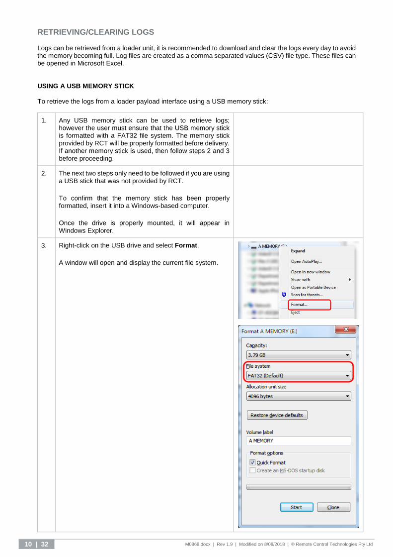
1. Any USB memory stick can be used to retrieve logs; however the user must ensure that the USB memory stick is formatted with a FAT32 file system. The memory stick provided by RCT will be properly formatted before delivery. If another memory stick is used, then follow steps 2 and 3 before proceeding.
2. The next two steps only need to be followed if you are using a USB stick that was not provided by RCT. To confirm that the memory stick has been properly formatted, insert it into a Windows-based computer. Once the drive is properly mounted, it will appear in Windows Explorer.
3. Right-click on the USB drive and select Format. A window will open and display the current file system.

M0868.docx | Rev 1.9 | Modified on 8/08/2018 | © Remote Control Technologies Pty Ltd 11 | 32
4. Insert the USB drive into the USB port connected to the payload display.
5. Select the Logs button on the payload display and then select Save Logs to USB by pressing the selection dial.
6. If a USB stick is not inserted, the payload display will prompt the user to insert one. Once inserted, the payload display may take a few seconds to properly mount it.
7. Once a memory stick is mounted, select OK by pressing the selection dial. The payload display will confirm if the save is successful. The logs will be saved onto USB drive on the top folder as a comma-separated values file (CSV). This file will be named as follows: ■ Log_[Loader ID]_[YYYYMMDDHHMMSS].
For example: Log_LD1_20141213143612 is a log taken from LD1 at 2:36pm on the 13th of December 2014. This CSV file can be opened using Microsoft Excel software; if the information is not readable try expanding the column width.
8. To clear the logs, press the Logs button, the Logging window will open. Use the selection dial to highlight Clear Logs. Press in the selection dial once. The payload display will show a screen confirming that the logs are cleared.
9. To clear the logs press the Logs button, the Logging window will open. Use the selection dial to highlight Clear Logs. Press in the selection dial once. The payload display will show a screen confirming that the logs are cleared.

12 | 32 M0868.docx | Rev 1.9 | Modified on 8/08/2018 | © Remote Control Technologies Pty Ltd
REMOTE PAYLOAD DISPLAY SYSTEMS COMPATIBILITY DIAGRAM
STANDARD RECEIVER
NOTE: THIS RECEIVER WILL ACCEPT READINGS FROM ALL THESE
TRUCKS FITTED WITH 470 MHz TRANSMITTERS
RCT APN 12082 KOMATSU PLM II ELECTRIC DRIVE
KOMATSU PLM II MECHANICAL DRIVE
HITACHI
CATERPILLAR TPMS
CATERPILLAR VIMS
M0868.docx | Rev 1.9 | Modified on 8/08/2018 | © Remote Control Technologies Pty Ltd 13 | 32
INSTALLATION GUIDE ANTENNA INSTALLATION
Mount the antennas away from other radio antennas to avoid interference and inter-modulating signals. Ideally, all antennas should be mounted one metre apart from each other and one metre clear from any other metal structures. Ensure that all corresponding antennas are mounted on the same plane, either vertical or horizontal. For example, if the truck antennas are mounted vertically, then the loader antenna should also be mounted vertically; this will ensure the best performance possible. Note: Always check the frequencies of other radios operating in the vicinity to ensure that they are separated from the frequencies that the remote payload system operates on. CHANNEL SELECTION The remote payload display system can be configured to operate on one of eight available channels. The truck interfaces and the remote receivers must be operating on the same channel to communicate correctly. Channels may be selected in several ways: 1. No link or channel switch will default to ‘Channel 1’. 2. A permanent link between pins as per the following table can be made in an RCT 0073 MS connector to
select a specific channel (pre-made channel selector plugs are also available from RCT (part numbers 10032 – 10039 for channels 1-8 respectively).
3. Fit an RCT 11594 16-channel selector switch. This is the most common system as the operators can
simply select which loading circuit they are operating on.
it is recommended that a permanent link is used for loaders, and a 16-channel selector is installed on every truck.
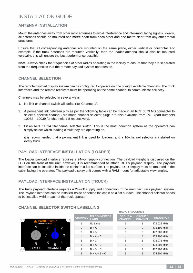
PAYLOAD INTERFACE INSTALLATION (LOADER) The loader payload interface requires a 24-volt supply connection. The payload weight is displayed on the LCD on the front of the unit; however, it is recommended to attach RCT’s payload display. The payload interface can be installed inside the cabin on a flat surface. The payload LCD display must be mounted in the cabin facing the operator. The payload display unit comes with a RAM mount for adjustable view angles. PAYLOAD INTERFACE INSTALLATION (TRUCK) The truck payload interface requires a 24-volt supply and connection to the manufacturers payload system. The Payload interface can be installed inside or behind the cabin on a flat surface. The channel selector needs to be installed within reach of the truck operator. CHANNEL SELECTOR SWITCH LABELLING
RADIO FREQUENCY
CHANNEL MS CONNECTOR LINKS GROUP A
CHANNEL GROUP B CHANNEL FREQUENCY
1 No Links 1 1 472.025 MHz 2 D + A 2 2 473.100 MHz 3 D + B 3 3 472.300 MHz 4 D + A + B 4 4 473.900 MHz 5 D + C 5 5 472.075 MHz 6 D + A + C 6 6 473.500 MHz 7 D + B + C 7 7 472.700 MHz 8 D + A + B + C 8 8 474.300 MHz

14 | 32 M0868.docx | Rev 1.9 | Modified on 8/08/2018 | © Remote Control Technologies Pty Ltd
DIAGRAMS TRUCK PAYLOAD INTERFACE EXTERNAL WIRING (477z)
MACHINE MAKE ANDMODEL
PAYLOADSYSTEM
REQUIREDLOOM
CAT EARLY TPMS 8256CAT LATE VIMS 1446KOMATSU 630E PLM2 2061KOMATSU 730E PLM2 2061KOMATSU 830E PLM2 2061KOMATSU 830E PLM3 3789KOMATSU 930E PLM3 3789KOMATSU HD1500-5 PLM2 2061KOMATSU HD1500-7 VHMS 2061KOMATSU HD785-3 PLM3 3276KOMATSU HD785-3 PLM2 3276KOMATSU HD785-5 PLM2 3276KOMATSU HD785-7 VHMS 3276HITACHI EH1100-3 HTMC 12135HITACHI EH1700-3 HTMC 12135
OPTIONAL EXTERNALLARGE DIGIT
DISPLAY BOARDS
POWER AND DATAPORT
PIN FUNCTION
A +VEB RS232 RXC RS232 TXD GNDE CAN HIF CAN LOW
PROGRAMMING PORTSERIAL BAUD RATE 38400
PIN FUNCTION
A RXB 0 VC TX
DISPLAY CONNECTORSSERIAL BAUD RATE 2400
PIN FUNCTION
1 +VE2 -VE3 NOT USED4 TX
(9755)
CHANNELSELECTION
POWER /DATA
PROGRAMMINGPORT
PAYLOADDISPLAY
INTERFACE(12082)
A F
E
DC
B A C
B
1 2
4 3
DISPLAY 2COMMS 2
ANTENNA
1 2
4 3
DISPLAY 1
16 CHANNEL SELECTOR(11594)
1
5
37
8 2
6 4
A
BCHANNELGROUP
87654321
A
B
C
D
E
F
G
H
I
J
K
L
A
B
C
D
E
F
G
H
I
J
K
L
87654321
A4
COPYRIGHT - ALL RIGHTS RESERVEDThis drawing is the property of REMOTECONTROL TECHNOLOGIES PTY LTD (RCT),and is not to be copied or used in whole or inpart for any purpose without the expressauthority of RCT. The drawing is to be returnedto RCT, on demand.
PAYLOAD EXTERNALDISPLAY (TRUCK
UNIT)
EXTERNAL LAYOUT
www.rct.net.au
UNCONTROLLED DOCUMENT
REV
4DWG No 477z
STATUS
NTSSCALE
Released
SHEET 1 of 1
BY EYDRN CW DATE 20/05/13APPD BT DATE 11/02/14
STOCKCODE ET-TRK-PLD-ADV
PARTNO 12082
3rd ANGLEPROJECTION
ALL DIMENSIONS IN MILLIMETERS
REV ZONE DESCRIPTION BY DATE
1 MODIFIED AND ADDEDTO TABLES AD 28/05/14
2 ALL
Added 3258, 12021,8893, antenna, comms2,
channel select oninterface, 12135 to table,
panel modified
AD 23/10/14
3 A7
APN for aerial changed
AD 21/09/15
4 A2-C5,D2
8893 updated to 11594,APN 12082 added
JB 29/09/17
M0868.docx | Rev 1.9 | Modified on 8/08/2018 | © Remote Control Technologies Pty Ltd 15 | 32
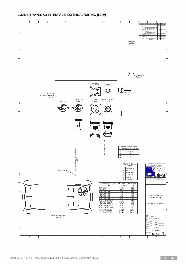
LOADER PAYLOAD INTERFACE EXTERNAL WIRING (524v)
CHANNELSELECTION
POWER /DATA
PROGRAMMINGPORT
A F
E
DC
B A C
B
1 2
4 3
DISPLAY 2COMMS 2
ANTENNA
1 2
4 3
DISPLAY 1
PR
OG
RA
MM
ING
LO
OM
(331
4)
PROGRAMMING PORTSERIAL BAUD RATE 38400
PIN FUNCTION
A RXB 0 VC TX
PAYLOADLOADER INTERFACE
(12175)
ANTENNA(9755)
CABLE & BASE(9522)
BRACKET(4723)
PAYLOAD DISPLAY(12201)
USB PORT DIS
PLA
Y L
OO
M F
OR
PA
YLO
AD
(118
93)
MACHINE MAKE ANDMODEL
PAYLOADSYSTEM
REQUIREDLOOM
CAT EARLY TPMS 8256CAT LATE VIMS 1446KOMATSU 630E PLM2 2061KOMATSU 730E PLM2 2061KOMATSU 830E PLM2 2061KOMATSU 830E PLM3 3789KOMATSU 930E PLM3 3789KOMATSU HD1500-5 PLM2 2061KOMATSU HD1500-7 VHMS 2061KOMATSU HD785-3 PLM3 3276KOMATSU HD785-3 PLM2 3276KOMATSU HD785-5 PLM2 3276KOMATSU HD785-7 VHMS 3276HITACHI EH1100-3 HTMC 12135HITACHI EH1700-3 HTMC 12135
POWER AND DATAPORT
PIN FUNCTION
A +VEB RS232 RXC RS232 TXD GNDE CAN HIF CAN LOW
87654321
A
B
C
D
E
F
G
H
I
J
K
L
A
B
C
D
E
F
G
H
I
J
K
L
87654321
A4
COPYRIGHT - ALL RIGHTS RESERVEDThis drawing is the property of REMOTECONTROL TECHNOLOGIES PTY LTD (RCT),and is not to be copied or used in whole or inpart for any purpose without the expressauthority of RCT. The drawing is to be returnedto RCT, on demand.
SERIES 2 PAYLOADLOADER 470 MHZ
EXTERNAL WIRING
www.rct-global.com
UNCONTROLLED DOCUMENT
REV
5DWG No 524v
STATUS
NTSSCALE
Released
SHEET 1 of 1
BY ADDRN RH DATE 27/10/14APPD AD DATE 30/10/14
STOCKCODE ET-LD-PLD-ADV
PARTNO 12175
3rd ANGLEPROJECTION
ALL DIMENSIONS IN MILLIMETERS
REV ZONE DESCRIPTION BY DATE
1 A6-7 APN for aerial updated AD 21/09/15
2A1-D4,A6,D6,C6,I4
16 ch selector replaces 8ch, ch select plu gto 6 pin,antenna/loom apnsupdated
AD 14/07/16
3 I5-K7,J8, K3
added table and titlechange, change todisplay text/apn
DH 06/06/17
4 B2-C6 11594 removed JB 29/08/17
5 L3payload display APN
changed MT 08/08/18

16 | 32 M0868.docx | Rev 1.9 | Modified on 8/08/2018 | © Remote Control Technologies Pty Ltd
SYSTEM LAYOUT (524u)
LAR
GE
DIG
IT DISPLAY
(4557)
OP
TION
AL E
XTERN
ALLA
RG
E D
IGIT
DIS
PLA
Y B
OAR
DS
DIS
PLA
Y C
ON
NEC
TOR
SS
ER
IAL B
AU
D R
ATE 2400P
INFU
NC
TION
1+VE
2-V
E3
RX
4TX
AN
TENN
A(9755)
CH
AN
NEL
SE
LEC
TION
PO
WE
R /
DA
TAP
RO
GR
AM
MIN
GP
OR
T
PA
YLO
ADTR
UC
K IN
TERFA
CE
(12082)
AFE
DC B
AC
B
12
43
DIS
PLA
Y 2C
OM
MS 2
AN
TENN
A
12
43
DIS
PLA
Y 1
CH
AN
NEL
SE
LEC
TION
PO
WE
R /
DA
TAP
RO
GR
AM
MIN
GP
OR
T
PA
YLO
ADLO
AD
ER
INTER
FACE
(12175)
AFE
DC B
AC
B
12
43
DIS
PLA
Y 2C
OM
MS 2
AN
TENN
A
12
43
DIS
PLA
Y 1
3314(O
NLY
CO
NN
EC
TED FO
RP
RO
GR
AM
MIN
G)
(ON
LY C
ON
NE
CTED
FOR
PR
OG
RA
MM
ING
)
LARGE DIGIT DISPLAY LOOM(10064)
LARGE DIGIT DISPLAY LOOM(1554)
LAR
GE
DIG
IT DISPLAY
(4557)
PROGRAMMING LOOM(3314)
CA
BLE
& B
ASE(9522)
BR
AC
KET(4723)
AN
TENN
A(9755)
CA
BLE
& B
ASE(9522)
BR
AC
KET(4723)
16 CH
ANN
EL SE
LEC
TOR
(11594)
15
37
82
64
ABC
HA
NN
ELG
RO
UP
EA
RTH
TRA
CK
® P
AY
LOA
D LO
AD
ER
/DIG
GE
R M
AC
HIN
E LA
YO
UT
EA
RTH
TRA
CK
® P
AY
LOA
D TR
UC
K M
AC
HIN
E LA
YO
UT
INC
LUD
ING
OP
TION
AL E
XTE
RN
AL LA
RG
E D
ISP
LAY
S
EAR
THTR
AC
K®
PAYLO
AD
SERIES 2 W
ITH LO
GG
ING
MA
CH
INE SYSTEM
LAYO
UTS
MA
CH
INE
MA
KE AND
MO
DEL
PA
YLO
ADS
YS
TEM
REQ
UIR
EDLO
OM
CA
T EAR
LYTP
MS
8256C
AT LATE
VIM
S1446
KO
MA
TSU
630EP
LM2
2061K
OM
ATS
U 730E
PLM
22061
KO
MA
TSU
830EP
LM2
2061K
OM
ATS
U 830E
PLM
33789
KO
MA
TSU
930EP
LM3
3789K
OM
ATS
U H
D1500-5
PLM
22061
KO
MA
TSU
HD
1500-7V
HM
S2061
KO
MA
TSU
HD
785-3P
LM3
3276K
OM
ATS
U H
D785-3
PLM
23276
KO
MA
TSU
HD
785-5P
LM2
3276K
OM
ATS
U H
D785-7
VH
MS
3276H
ITACH
I EH
1100-3H
TMC
12135H
ITACH
I EH
1700-3H
TMC
12135
PO
WE
R A
ND
DATA
PO
RT
PIN
FUN
CTIO
NA
+VEB
RS
232 RX
CR
S232 TX
DG
ND
EC
AN H
IF
CAN
LOW
TO LO
ADER
24V S
UPPLY
PA
YLO
AD
DISPLAY
(12201)
USB PO
RT
DISPLAY LOOM FOR PAYLOAD(11893)
POWER LOOM LOADER(3002)
12
34
56
78
910
1112
B ACDEFGH
B ACDEFGH
12
34
56
78
910
1112
A4
CO
PY
RIG
HT - A
LL RIG
HTS R
ESERVED
This draw
ing is
the property
of R
EM
OTE
CO
NTR
OL TE
CH
NO
LOG
IES P
TY LTD (R
CT),
and is not to be copied or used in whole or in
part for
any purpose
without
the express
authority of RC
T. The drawing is to be returned
to RC
T, on demand.
SE
RIE
S 2 PAYLO
ADS
YS
TEM
OV
ERVIEW
470 MH
Z
EXTER
NA
L WIR
ING
ww
w.rct.net.au
UN
CO
NTR
OLLE
D D
OC
UM
ENT
REV4
DW
G N
o524u
STA
TUS
NTS
SC
ALE
Released
SH
EET1 of 1
BYAD
DR
NR
HD
ATE24/10/14
APPD
ADD
ATE30/10/14
STO
CK
CO
DE
----
PAR
TN
O----
3rd AN
GLE
PR
OJE
CTIO
N
ALL D
IMEN
SIO
NS IN
MILLIM
ETER
S
REV
ZON
ED
ESC
RIP
TION
BYD
ATE
1
A1-C
4,A
7-C9,
A5-C
5,A
10-C1
0,B11,F9
16 ch selector replaces 8ch, ch select plug to 6 pin,antenna/loom
apnsupdated
AD14/07/16
2A
2-A9,G
4-H5,
H8-9
added table, headingsand page title, change todisplay text/apn
DH
06/06/17
3B
7-C10 11594 rem
oved fromdigger/m
achine layoutJB
29/09/17
4H
8payload display A
PNchanged
MT
08/08/18

M0868.docx | Rev 1.9 | Modified on 8/08/2018 | © Remote Control Technologies Pty Ltd 17 | 32
TRUCK LOOM CONFIGURATION SELECTION
In order to communicate with different manufacturer payload systems, trucks may require different looms. Use the lookup table below to select the appropriate loom for each truck type that is compatible with the interface.
TRUCK MAKE TRUCK MODEL
PAYLOAD SYSTEM REQUIRED LOOM DRAWING NUMBER
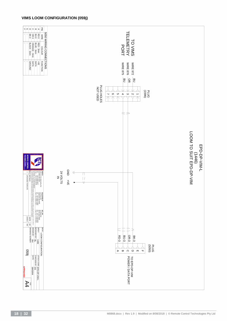
CAT (LATE) ALL VIMS VIMS 1446 059j
CAT (EARLY) ALL TPMS TPMS 8256 018k
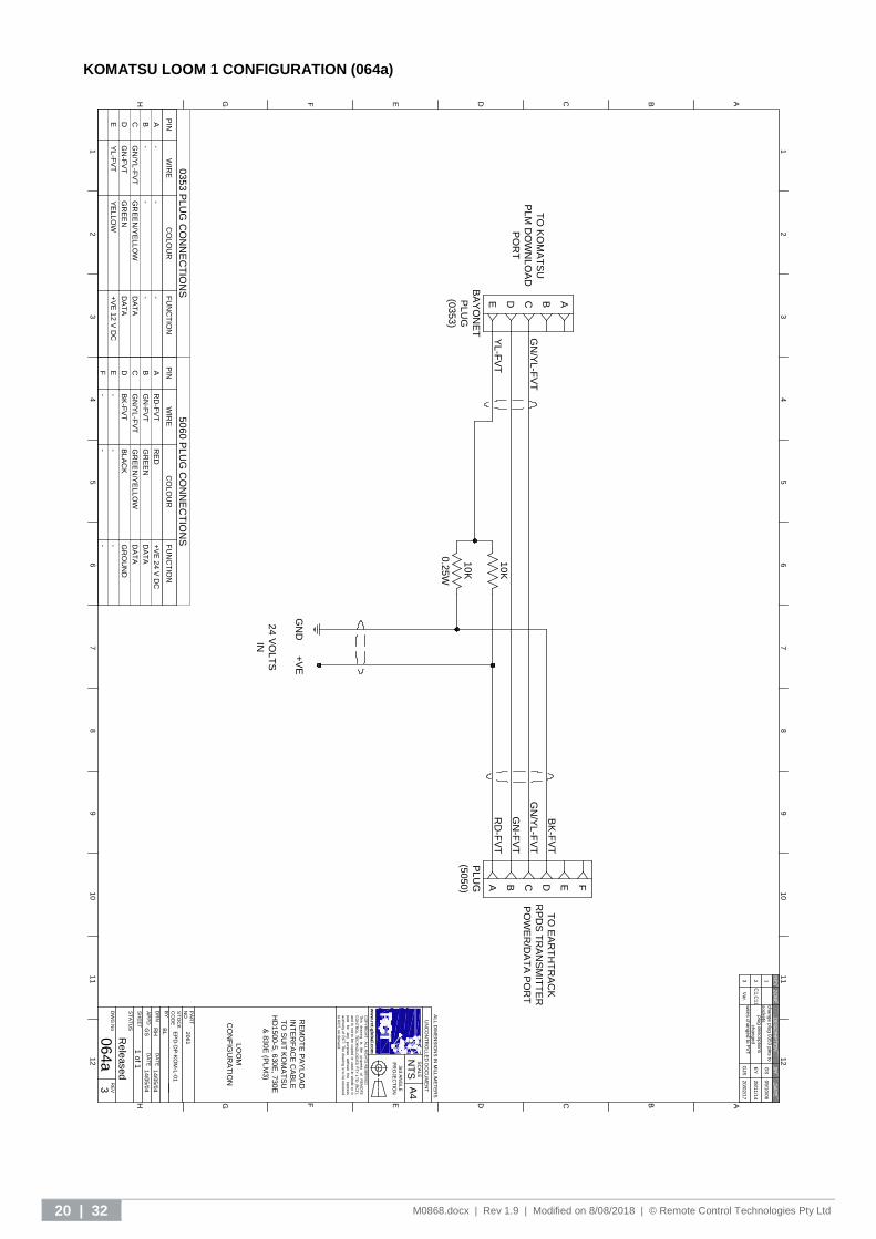
KOMATSU 630E PLM2 2061 064a
KOMATSU 730E PLM2 2061 064a
KOMATSU 830E PLM2 2061 064a
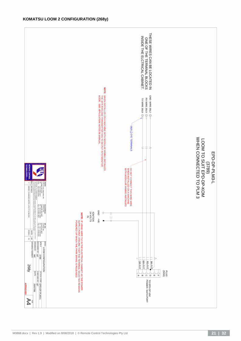
KOMATSU 830E PLM3 3789 268y
KOMATSU 930E PLM3 3789 268y
KOMATSU HD1500-5 PLM2 2061 064a
KOMATSU HD1500-7 VHMS (PLM3) 2061 064a
KOMATSU HD785-3 PLM3 3276 063ga
KOMATSU HD785-3 PLM2 3276 063ga
KOMATSU HD785-5 PLM2 3276 063ga
KOMATSU HD785-7 VHMS (PLM3) 3276 063ga
HITACHI EH1100-3 HTMC 12135 513d
HITACHI EH1700-3 HTMC 12135 513d
18 | 32 M0868.docx | Rev 1.9 | Modified on 8/08/2018 | © Remote Control Technologies Pty Ltd
VIMS LOOM CONFIGURATION (059j)
1234567
WIR
E 972
WIR
E 876
WIR
E 875
BUOR
BU
TO V
IMS
TELE
ME
TRY
PO
RT
PLU
G(1596)
PLU
G H
OLES
NO
T USED
FEDCBA
BK
-3
OR
-3
BU
-3
RD
-3
GN
D+VE
24 VO
LTSIN
PLU
G(5050)
TO E
PD
-DP-VIM
PO
WE
R / D
ATA POR
T
PTY LTDTECHNOLOGIESREM
OTE CONTROL
PERTH
Unit 2-5, 511 A
bernethy Rd
Kew
dale WA
6105P
h:Fax:
+61 8 9353 6577+61 8 9353 6578
KA
LGO
OR
LIE24 P
ercy Rd
Kalgoorlie W
A 6430
Ph:
Fax: +61 8 9021 1600+61 8 9091 4927
MT. ISA
1A R
yan Rd
Mt Isa Q
LD 4825
Ph:
Fax: +61 7 4749 0233+61 7 4749 0232
DES
C:
AP
N #:
STO
CK
CO
DE:
DES
IGN
ED
BY:C
HE
CK
ED
BY:D
RA
WN
BY:D
ATE:S
IZED
RA
WIN
G N
UM
BER:
REV
DETAILS
BYD
ATE
CO
PYR
IGH
T - ALL R
IGH
TS RE
SER
VED
This drawing is the property of R
EM
OTE
CO
NTR
OL TE
CH
NO
LOG
IES
PTY
LTD (R
CT), and is not to be copied or used in w
hole orin part for any purpose w
ithout the express authority of RC
T. The drawing is to be returned to R
CT, on dem
and.
LOO
M C
ON
FIGU
RA
TION
1446B
LR
H
EP
D-D
P-V
IM-L
GS
09/03/04
059jA
42
UPG
RA
DE
D TE
MPLATE
20/08/10M
M
EP
D-D
P-V
IM-L
(1446)LO
OM
TO S
UIT E
PD
-DP
-VIM
APPR
OVED
5050 WIR
ING
CO
NN
EC
TION
SP
INW
IRE
CO
LOU
RFU
NC
TION
AR
D-3
RE
D - 3m
m+V
EB
BU
-3B
LUE
- 3mm
DA
TAC
OR
-3O
RA
NG
E - 3m
mD
ATA
DB
K-3
BLA
CK
- 3mm
GR
OU
ND
E-
--
F-
--

M0868.docx | Rev 1.9 | Modified on 8/08/2018 | © Remote Control Technologies Pty Ltd 19 | 32
CATERPILLAR (EARLY) LOOM CONFIGURATION (018k)
ABCDEA B C D E F
1234W
IRE 4
WIR
E 3
WIR
E 2
WIR
E 1
NO
T USED
NO
T USED
(5050)
(0322)
(0320)
PTY LTDTECHNOLOGIESREM
OTE CONTROL
PERTH
(HEA
D O
FFICE)
Unit 2-5, 511 A
bernethy Rd
Kew
dale WA
6105P
h:Fax:
+61 (0) 8 9353 6577+61 (0) 8 9353 6578
DE
SC
:
AP
N #:
STO
CK
CO
DE
:
DE
SIG
NE
D B
Y:
CH
EC
KE
D B
Y:
DR
AW
N B
Y:
DA
TE:
SIZE
DR
AW
ING
NU
MB
ER
:R
EV
DE
TAILS
BY
DA
TE
CO
PYR
IGH
T - ALL R
IGH
TS RESER
VEDThis draw
ing is the property of REM
OTE C
ON
TRO
L TEC
HN
OLO
GIES
PTY
LTD (R
CT), and is not to be copied or used in w
hole orin part for any purpose w
ithout the express authority of RC
T. The drawing is to be returned to R
CT, on dem
and.
LOO
M C
ON
FIGU
RATIO
N
8256BLR
H
EP
D-D
P-LG
JS31/08/04
018kA
4
EP
D-D
P-L(8256)
RE
MO
TE P
AY
LOA
D IN
TERFAC
E CABLE
KA
LGO
OR
LIEP
h: +61 (0) 8 9021 1600
MT ISA
Ph: +61 (0) 7 4749 0233
BR
ISBA
NE
Ph: +61 (0) 7 3385 0172
MELB
OU
RN
EP
h: +61 (0) 3 9545 5859w
ww
.rct.net.au
AFR
ICA
Ph: +27 (0) 83 292 4246
APPR
OVED
WIR
E LEG
END
BK
-B
LAC
KP
K-
PIN
KBU
-B
LUE
PU-
PU
RPLE
BN-
BR
OW
NR
D-
RED
GN
-G
RE
ENW
H-
WH
ITEG
Y-
GR
EYY
L-
YE
LLOW
OR
-O
RA
NG
ETQ
-TU
RQ
UO
ISE
20 | 32 M0868.docx | Rev 1.9 | Modified on 8/08/2018 | © Remote Control Technologies Pty Ltd
KOMATSU LOOM 1 CONFIGURATION (064a)
ABCDE
FEDCBAY
L-FVT
TO K
OM
ATSUP
LM D
OW
NLO
ADP
OR
T
GN
/YL-FVT
RD
-FVT
GN
-FVT
GN
/YL-FVT
BK
-FVT
10K
10K
0.25W
GN
D+VE
24 VOLTS
IN
PLU
G(5050)
BAY
ON
ETP
LUG
(0353)
TO EA
RTH
TRAC
KR
PDS TR
ANSM
ITTERP
OW
ER/D
ATA POR
T
12
34
56
78
910
1112
B ACDEFGH
B ACDEFGH
12
34
56
78
910
1112
A4
CO
PY
RIG
HT - A
LL RIG
HTS R
ESERVED
This draw
ing is
the property
of R
EMO
TEC
ON
TRO
L TECH
NO
LOG
IES PTY LTD
(RC
T),and is not to be copied or used in w
hole or inpart
for any
purpose w
ithout the
expressauthority of R
CT. The draw
ing is to be returnedto R
CT, on dem
and.
RE
MO
TE P
AY
LOA
DIN
TER
FAC
E C
AB
LETO
SU
IT KO
MA
TSU
HD
1500-5, 630E, 730E
& 830E
(PLM
3)
LOO
MC
ON
FIGU
RA
TION
ww
w.rct-global.com
UN
CO
NTR
OLLE
D D
OC
UM
ENT
REV3
DW
G N
o064a
STA
TUS
NTS
SC
ALE
Released
SH
EET
1 of 1
BY
BL
DR
NR
HD
ATE
14/05/04A
PPD
GS
DA
TE14/05/04
STO
CK
CO
DE
EPD
-DP-KO
M-L-01
PA
RT
NO
2061
3rd AN
GLE
PR
OJE
CTIO
N
ALL D
IME
NS
ION
S IN
MILLIM
ETERS
0353 PLUG
CO
NN
EC
TION
SP
INW
IRE
CO
LOU
RFU
NC
TION
A-
--
B-
--
CG
N/Y
L-FVT
GR
EE
N/Y
ELLO
WD
ATA
DG
N-FV
TG
RE
EN
DA
TAE
YL-FV
TY
ELLO
W+V
E 12 V
DC
5060 PLUG
CO
NN
EC
TION
SP
INW
IRE
CO
LOU
RFU
NC
TION
AR
D-FV
TR
ED
+VE
24 V D
CB
GN
-FVT
GR
EE
ND
ATA
CG
N/Y
L-FVT
GR
EE
N/Y
ELLO
WD
ATA
DB
K-FV
TB
LAC
KG
RO
UN
DE
--
-F
--
-
REV
ZON
ED
ES
CR
IPTION
BY
DA
TE
1change plug 0353 pins tosockets
GS
09/10/06
2C
1,C11
plug descriptionschanged
EY
28/11/14
3V
ar.w
ires changed to FVTG
JS20/02/17
M0868.docx | Rev 1.9 | Modified on 8/08/2018 | © Remote Control Technologies Pty Ltd 21 | 32
KOMATSU LOOM 2 CONFIGURATION (268y)
GN
D. W
IRE 35L2
RX W
IRE 35L9
TX WIR
E 35L8
THE
SE
WIR
ES
CA
N B
E LO
CATED
INO
NE
OF TH
E TE
RM
INAL BLO
CKS
INS
IDE
THE
ELC
TRIC
AL C
ABINET.
FEDCBA
BK-FVT
RD
-FVT
WH
-FVT
OR
-FVT
GN
D+VE
IGN
ITION
24 VOLTS
IN
PLUG
(5050)
TO EPD
-DP-VIM
POW
ER / D
ATA POR
T
0825 316 EYE TERM
INALS
DO
NO
T CO
NN
ECT TH
IS WIR
E WIR
EW
HEN
INSTALLED
ON
A MAC
HIN
EW
ITH M
OD
ULAR
MIN
ING
INSTALLED
NO
TE:W
HEN
INSTALLED
ON
A MAC
HIN
E WITH
MO
DU
LAR M
ININ
G IN
STALLED,
THE 3275 PAYLO
AD TR
ANSM
ITTER H
AS TO BE PU
T INTO
MO
NITO
R
MO
DE. SEE APPLIC
ATION
NO
TES IN M
ANU
AL.
NO
TE:IF U
SING
WIR
E 712 IN TH
E ELECTR
ICAL C
ABINET AS TH
E POW
ER SU
PPLY POIN
T, ENSU
RE TH
AT THE TER
MIN
AL SELECTED
REM
AINS
POW
ERED
UP W
HEN
THE PAR
K BRAKE IS R
ELEASED.
PTY LTDTECHNOLOGIESREM
OTE CONTROL
PERTH
Unit 2-5, 511 A
bernethy Rd
Kew
dale WA
6105P
h:Fax:
+61 8 9353 6577+61 8 9353 6578
KA
LGO
OR
LIE24 P
ercy Rd
Kalgoorlie W
A 6430
Ph:
Fax: +61 8 9021 1600+61 8 9091 4927
MT. ISA
1A R
yan Rd
Mt Isa Q
LD 4825
Ph:
Fax: +61 7 4749 0233+61 7 4749 0232
DES
C:
AP
N #:
STO
CK
CO
DE:
DES
IGN
ED
BY:C
HE
CK
ED
BY:D
RA
WN
BY:D
ATE:S
IZED
RA
WIN
G N
UM
BER:
REV
DETAILS
BYD
ATE
CO
PYR
IGH
T - ALL R
IGH
TS RE
SER
VED
This drawing is the property of R
EM
OTE
CO
NTR
OL TE
CH
NO
LOG
IES
PTY
LTD (R
CT), and is not to be copied or used in w
hole orin part for any purpose w
ithout the express authority of RC
T. The drawing is to be returned to R
CT, on dem
and.
LOO
M C
ON
FIGU
RA
TION
3789B
TM
C
EP
D-D
P-P
LM3-L
BT20/07/06
268yA
43
AD
DED
/ CH
AN
GED
NO
TES, U
PG
TITLE BLOC
K05/08/11
JG
EP
D-D
P-P
LM3-L
(3789)LO
OM
TO S
UIT E
PD
-DP
-KO
MW
HE
N C
ON
NE
CTE
D TO
PLM
3
APPR
OVED

22 | 32 M0868.docx | Rev 1.9 | Modified on 8/08/2018 | © Remote Control Technologies Pty Ltd
KOMATSU LOOM 3 CONFIGURATION (063ga)
YL-FVT
TO KO
MA
TSUP
LM D
OW
NLO
ADP
OR
T
GN
/YL-FVT
RD
-FVT
GN
-FVT
GN
/YL-FVT
BK-FVT
10K
10K
0.25W
GN
D+VE
24 VO
LTSIN
PLU
G(5050)
SC
REW
TYPE PLU
G(0322)
TO EA
RTH
TRA
CK
PO
WER
/DATA PO
RT
GN
-FVT
BK-FVT
RD-FVT
ABCDEA B C D E F
12
34
56
78
910
1112
B ACDEFGH
B ACDEFGH
12
34
56
78
910
1112
A4
CO
PY
RIG
HT - A
LL RIG
HTS R
ESERVED
This draw
ing is
the property
of R
EM
OTE
CO
NTR
OL TE
CH
NO
LOG
IES PTY LTD
(RC
T),and is not to be copied or used in w
hole or inpart
for any
purpose w
ithout the
expressauthority of R
CT. The draw
ing is to be returnedto R
CT, on dem
and.
RE
MO
TE PAYLO
ADIN
TERFA
CE
CABLE
TO SU
IT KO
MATSU
HD
1500-7, HD
785-3,H
D785-5 &
HD
785-7
LOO
MC
ON
FIGU
RA
TION
ww
w.rct.net.au
UN
CO
NTR
OLLED
DO
CU
MEN
T
REV2
DW
G N
o063ga
STA
TUS
NTS
SC
ALE
Released
SH
EET
1 of 1
BY
BL
DR
NE
LCD
ATE
15/06/01A
PPD
GS
DA
TE15/06/01
STO
CK
CO
DE
EP
D-D
P-KO
M-L
PA
RT
NO
3276
3rd AN
GLE
PR
OJE
CTIO
N
ALL D
IMEN
SION
S IN M
ILLIME
TER
S
REV
ZON
ED
ESC
RIP
TION
BY
DA
TE
12B
2,C1,
C11
Text changes to pluglabels and 0322
descriptionE
Y28/11/14
0322 PLUG
CO
NN
EC
TION
SP
INW
IRE
CO
LOU
RFU
NC
TION
A-
--
B-
--
CG
N/YL-FVT
GR
EE
N/Y
ELLO
W - FVT
DATA
DG
N-FVT
GR
EEN
- FVTD
ATAE
YL-FVT
YELLO
W - FVT
+VE 12 V D
C
5050 PLUG
CO
NN
EC
TION
SP
INW
IRE
CO
LOU
RFU
NC
TION
AR
D-FVT
RED
- FVT+VE
24 V DC
BG
N-FVT
GR
EEN
- FVTD
ATAC
GN
/YL-FVTG
RE
EN
/YE
LLOW
- FVTD
ATAD
BK-FVT
BLA
CK
- FVTG
RO
UN
DE
--
-F
--
-
All
Redraw
nG
S18/09/07

M0868.docx | Rev 1.9 | Modified on 8/08/2018 | © Remote Control Technologies Pty Ltd 23 | 32
HITACHI LOOM CONFIGURATIONI (513d )
ABC
WH
-FVTBE
BN
-FVTB
F
(2183)(2024)
TO H
TMC
CA
N B
US 2
PO
RT
AB
K-FVTC
ABCDEF
RD
-FVTC
WH
-FVTAA
BN
-FVTAB
BK-FVT BD
RD-FVT BA
TO EP
D-H
TMX
-ED
-TXP
OW
ER
/DA
TA POR
TB
+VE
GR
OU
ND
CA
N H
I
CA
N LO
+VE
GROUND
24 VO
LTS INC
(5050)P
LUG
REV
ZON
ED
ES
CR
IPTION
BY
DA
TE
12
34
56
78
910
1112
B ACDEFGH
B ACDEFGH
12
34
56
78
910
1112
A4
CO
PYR
IGH
T - ALL R
IGH
TS R
ESER
VEDThis
drawing
is the
property of
REM
OTE
CO
NTR
OL TEC
HN
OLO
GIES PTY LTD
(RC
T),and is not to be copied or used in w
hole or inpart
for any
purpose w
ithout the
expressauthority of R
CT. The draw
ing is to be returnedto R
CT, on dem
and.
LOO
M TO
SU
ITE
PD
-HTM
X-E
D-TX
LOO
MC
ON
FIGU
RA
TION
ww
w.rct-global.com
UN
CO
NTR
OLLE
D D
OC
UM
EN
T
REV0
DW
G N
o513d
STA
TUS
NTS
SC
ALE
Released
SH
EET
1 of 1
BY
JBD
RN
RH
DA
TE09/06/14
AP
PDJB
DA
TE09/06/14
STO
CK
CO
DE
EPD
-HTM
X-ED
-TX-L
PA
RT
NO
12135
3rd AN
GLE
PR
OJE
CTIO
N
ALL D
IME
NS
ION
S IN
MILLIM
ETERS
WIR
E LEG
END
BK
-B
LAC
KP
K-
PIN
KB
U-
BLU
EP
U-
PU
RPLE
BN
-B
RO
WN
RD
-R
ED
GN
-G
RE
ENW
H-
WH
ITEG
Y-
GR
EYY
L-
YE
LLOW
OR
-O
RA
NG
ETQ
-TU
RQ
UO
ISE

24 | 32 M0868.docx | Rev 1.9 | Modified on 8/08/2018 | © Remote Control Technologies Pty Ltd
LOADER LOOM CONFIGURATION (019v)
BU-4
BN-4
GR
OU
ND
+VE
24 VOLTS
IN
MS 3106E14S-6S
TO EO
D-R
D
A B C D E F
12
34
56
78
910
1112
B ACDEFGH
B ACDEFGH
12
34
56
78
910
1112
A4
CO
PYR
IGH
T - ALL R
IGH
TS RESER
VEDThis
drawing
is the
property of
REM
OTE
CO
NTR
OL TEC
HN
OLO
GIES P
TY LTD (R
CT),
and is not to be copied or used in whole or in
part for
any purpose
without
the express
authority of RC
T. The drawing is to be returned
to RC
T, on demand.
RE
MO
TE PAYLO
ADP
OW
ER C
ABLE
LOO
MC
ON
FIGU
RATIO
N
ww
w.rct.net.au
UN
CO
NTR
OLLE
D D
OC
UM
ENT
RE
V0D
WG
No019v
STA
TUS
NTS
SC
ALE
Released
SH
EET
1 of 1
BY
BL
DR
NR
HD
ATE
22/04/04A
PPD
BL
DA
TE22/04/04
STO
CK
CO
DE
EPD
-RD
-L
PA
RT
NO
4885
3rd AN
GLE
PR
OJE
CTIO
N
ALL D
IME
NS
ION
S IN
MILLIM
ETERS
WIR
E LEG
END
BK-
BLA
CK
PK-
PIN
KB
U-
BLU
EP
U-
PU
RPLE
BN
-B
RO
WN
RD
-R
EDG
N-
GR
EEN
WH
-W
HITE
GY
-G
REY
YL
-Y
ELLO
WO
R-
OR
AN
GE
TQ-
TUR
QU
OISE
RE
VZO
NE
DE
SC
RIP
TION
BY
DA
TE

M0868.docx | Rev 1.9 | Modified on 8/08/2018 | © Remote Control Technologies Pty Ltd 25 | 32
CMP PAYLOAD MONITORING AND CONFIGURATION Connecting the unit to a computer via a 3314 programming lead and a serial adaptor allows you to monitor the payload and vehicle information and configure the unit. Using the CMP payload application you can easily monitor the payload and/or configure the unit to support the required vehicle type. CONNECTING TO THE PAYLOAD CONFIGURATION LOOM To connect to the payload configuration tool, follow the instructions provided below:
1. Connect the device to a computer that has the CMP Payload application.
2. Run the application, and select the correct COM port in the popup window.
MONITOR PAYLOAD STATUS
1. The start-up screen that is displayed is the Monitor Payload tab. This screen shows you the weight of the payload and the pressure being subjected to individual struts along with other useful data.
2. If the monitor payload screen is not displayed, simply select the Monitor Payload tab from the tab selections.

26 | 32 M0868.docx | Rev 1.9 | Modified on 8/08/2018 | © Remote Control Technologies Pty Ltd
CONFIGURING THE PAYLOAD INTERFACE
1. Select the Configure tab from the tab selections.
2. The Configure page allows you to change most of the task specific settings for any application.
1. NODE TYPE: This option decides the type of vehicle that the interface is installed onto. The options are
truck or loader. 2. PROTOCOL: This option tells the interface what onboard payload system the unit will be communicating
with. This is essential for trucks; however, the loader units do not need to communicate with the onboard payload systems. Options include TPMS (Caterpillar early models), VIMS (Caterpillar), VIMS 3G (Caterpillar new), PLM2 (Komatsu early), PLM3 (Komatsu) and HTMC (Hitachi).
3. MODEL: Selecting the truck model specifies the truck specific details to the interface such as maximum
weight. This setting does not affect loader units. 4. RADIO: This option sets up the communication method for the unit; currently, the units only support
MAXON radios. 5. ON AIR PROTOCOL: This option is used to specify what application the unit is being used for and what
protocol to use for COMs. Payload interfaces should have payload protocol selected. A series of inputs and check options are also available. These are EEProm size, unit ID, monitor only, latch display, US ton conversion, overload display, DIP truck select enable, and factory test. To apply any changes, click the Write Device button and power cycle the interface. The device will now use the specified configuration. Selecting the save configuration will allow users to create a ‘config file’ that can be loaded into any other units using the load configuration button.
M0868.docx | Rev 1.9 | Modified on 8/08/2018 | © Remote Control Technologies Pty Ltd 27 | 32
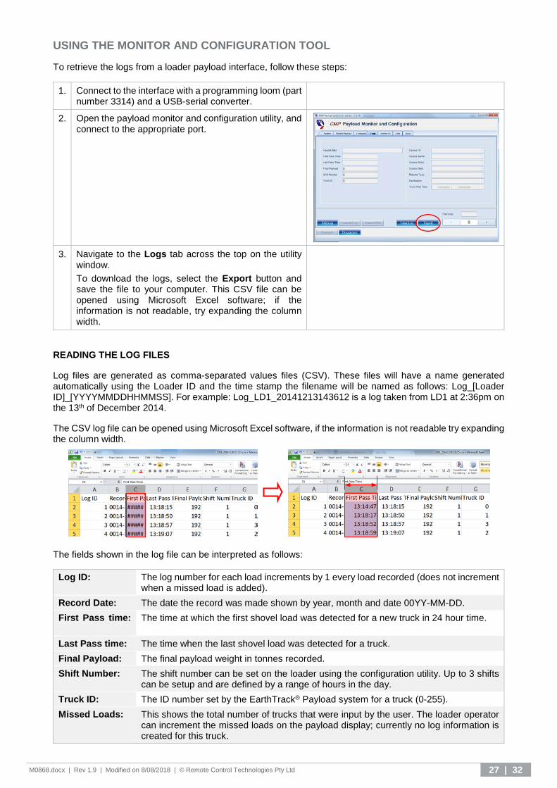
USING THE MONITOR AND CONFIGURATION TOOL To retrieve the logs from a loader payload interface, follow these steps:
1. Connect to the interface with a programming loom (part number 3314) and a USB-serial converter.
2. Open the payload monitor and configuration utility, and connect to the appropriate port.
3. Navigate to the Logs tab across the top on the utility
window. To download the logs, select the Export button and save the file to your computer. This CSV file can be opened using Microsoft Excel software; if the information is not readable, try expanding the column width.
READING THE LOG FILES Log files are generated as comma-separated values files (CSV). These files will have a name generated automatically using the Loader ID and the time stamp the filename will be named as follows: Log_[Loader ID]_[YYYYMMDDHHMMSS]. For example: Log_LD1_20141213143612 is a log taken from LD1 at 2:36pm on the 13th of December 2014. The CSV log file can be opened using Microsoft Excel software, if the information is not readable try expanding the column width.
The fields shown in the log file can be interpreted as follows:
Log ID: The log number for each load increments by 1 every load recorded (does not increment when a missed load is added).
Record Date: The date the record was made shown by year, month and date 00YY-MM-DD. First Pass time:
The time at which the first shovel load was detected for a new truck in 24 hour time.
Last Pass time: The time when the last shovel load was detected for a truck. Final Payload: The final payload weight in tonnes recorded. Shift Number: The shift number can be set on the loader using the configuration utility. Up to 3 shifts
can be setup and are defined by a range of hours in the day. Truck ID: The ID number set by the EarthTrack® Payload system for a truck (0-255). Missed Loads: This shows the total number of trucks that were input by the user. The loader operator
can increment the missed loads on the payload display; currently no log information is created for this truck.

28 | 32 M0868.docx | Rev 1.9 | Modified on 8/08/2018 | © Remote Control Technologies Pty Ltd
DIAGNOSTICS MODE Diagnostics mode is an option that can be used to see all data that each unit receives either a truck or a loader. On each model it is currently only activated by switching the 1st dipswitch on the CMP board to the on position. DIAGNOSTICS DIGGING LOADER If diagnostics mode is turned on in a loader unit the unit will no longer record truck logs, instead the log file will contain every packet that the loader receives. This assists by allowing technicians to see what trucks are transmitting and when there are transmission difficulties. The logs add up quickly and when full the unit will automatically overwrite the oldest logs. These logs can be extracted the same way as normal logs through the USB port on the payload or using a 3314 programming loom. DIAGNOSTICS LOGGING TRUCK If diagnostics mode is turn on in a truck unit the unit will log every change in details from the manufacturer’s payload system. This gives technicians a look into how the manufacturers equipment in functioning and will help see why logs may not be as expected for example when a loader creates a log that is significantly lower than the maximum payload weight. These logs can be extracted using a 3314 programming loom and the CMP payload utility. READING LOG DATA When the diagnostic logs are extracted the column titles will remain the same as for normal logs from a loader, the column will need to be renamed using the table below:
REGISTER NAME (REGULAR LOG FIELD) DIAGNOSTIC LOG FIELD Log ID Log ID Record Date Date 1st Pass Time Time Last Pass Time - Final Payload weight Payload Weight Shift Number Truck State Truck ID Truck ID Source Pit Truck state (on air) Source Bench Truck Model (Truck diagnostics only) Source Block Left Front Strut Pressure Source Blast Right Front Strut Pressure Material Type Left rear Strut Pressure Destination Right rear Strut Truck Wait time Accumulated error count
Some fields will not be used in the loader diagnostic logs such as Truck Model. The truck state is defined using a number from 0 to 6. These number correspond to the following states:
TRUCK STATE (NUMERIC) TRUCK STATE STATE SHORT HAND 0 Stopped empty SMT 1 Travelling empty TMT 2 Loading LDG 3 Stopped loading SLD 4 Travelling loaded TLD 5 Dumping DMP 6 Communication failure CF

M0868.docx | Rev 1.9 | Modified on 8/08/2018 | © Remote Control Technologies Pty Ltd 29 | 32
PARTS LIST
PART NO. DESCRIPTION 12175 Payload loader interface 12082 Payload truck interface 3258 Aerial and lead 4885 Power loom to suit loader 3314 Programming loom 12208 Payload display 11594 Channel Selector 16 position 10032 Channel selector plug (CH1) 10033 Channel selector plug (CH2) 10034 Channel selector plug (CH3) 10035 Channel selector plug (CH4) 10036 Channel selector plug (CH5) 10037 Channel selector plug (CH6) 10038 Channel selector plug (CH7) 10039 Channel selector plug (CH8)
* Refer to the Truck Loom Configuration Selection section on page 17 for information on truck looms.
TROUBLESHOOTING
FAULT REMEDY No weights or load distribution being displayed in loading machine.
1. Check the loading machine and truck are on the same channel. 2. Check that the four LCDs on the interface show the correct details, if they do, check the
payload display connections. (This may have been installed under the instrument panel.)
3. Set up the 0000 portable display near the loading machine and on the correct channel; then check if the portable device will show weights. a. If the portable unit displays correctly:
i. Confirm that the loading machine display supplies voltage greater than 22 volts DC.
ii. Check the loading machine display connections and antenna. iii. Check that the loading machine channel select switch is functioning
correctly. b. If the portable unit does not display any information:
i. Confirm that the portable display supply voltage is greater than 13 volts DC.
ii. Ensure that the OEM payload system is functioning correctly. iii. Confirm that the truck interface fitted is the correct configuration/part
number for the application. iv. Check the truck interface connections and antenna. v. Check that the truck interface channel select switch is functioning
correctly. vi. Check the version number of both the truck interface and remote
receivers to ensure they are the same version. If any units are found to differ in version numbers, contact RCT for assessment and quote for upgrade.
No weight shown on the truck large digit display or loader
1. Check that the truck interface is connected with a 24 V supply. 2. Check if the 4-line LCD display on the truck interface shows the weight. If it does, check
that the LCD is plugged correctly with the end labelled ‘To Display’ connected to the display.
3. Clear any logs in the manufacturer’s logging system. (For VIMS, this requires CAT VIMS PC software.)
Any unit found to have a suspected fault should be clearly marked with the reported fault, who identified the fault and what model machine it was fitted to, and then returned to RCT for assessment and quote on repair.
30 | 32 M0868.docx | Rev 1.9 | Modified on 8/08/2018 | © Remote Control Technologies Pty Ltd
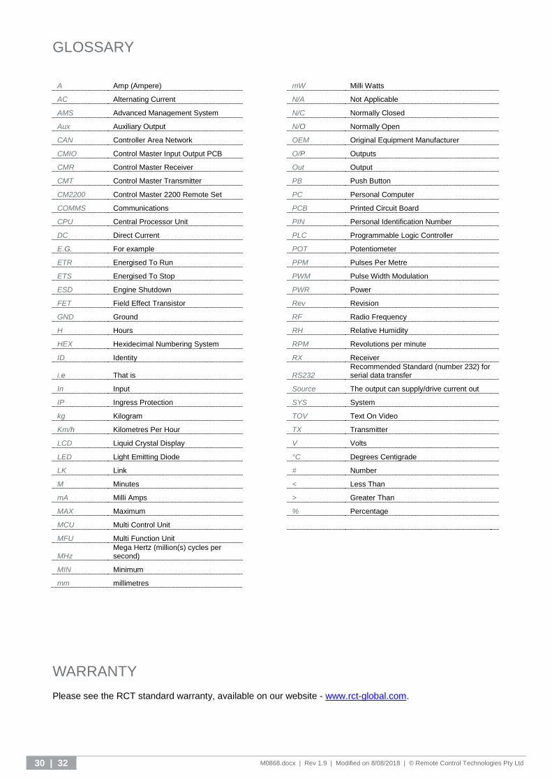
GLOSSARY
WARRANTY Please see the RCT standard warranty, available on our website - www.rct-global.com.
A Amp (Ampere) mW Milli Watts
AC Alternating Current N/A Not Applicable
AMS Advanced Management System N/C Normally Closed
Aux Auxiliary Output N/O Normally Open
CAN Controller Area Network OEM Original Equipment Manufacturer
CMIO Control Master Input Output PCB O/P Outputs
CMR Control Master Receiver Out Output
CMT Control Master Transmitter PB Push Button
CM2200 Control Master 2200 Remote Set PC Personal Computer
COMMS Communications PCB Printed Circuit Board
CPU Central Processor Unit PIN Personal Identification Number
DC Direct Current PLC Programmable Logic Controller
E.G. For example POT Potentiometer
ETR Energised To Run PPM Pulses Per Metre
ETS Energised To Stop PWM Pulse Width Modulation
ESD Engine Shutdown PWR Power
FET Field Effect Transistor Rev Revision
GND Ground RF Radio Frequency
H Hours RH Relative Humidity
HEX Hexidecimal Numbering System RPM Revolutions per minute
ID Identity RX Receiver
i.e That is
RS232 Recommended Standard (number 232) for serial data transfer
In Input Source The output can supply/drive current out
IP Ingress Protection SYS System
kg Kilogram TOV Text On Video
Km/h Kilometres Per Hour TX Transmitter
LCD Liquid Crystal Display V Volts
LED Light Emitting Diode °C Degrees Centigrade
LK Link # Number
M Minutes < Less Than
mA Milli Amps > Greater Than
MAX Maximum % Percentage
MCU Multi Control Unit
MFU Multi Function Unit
MHz Mega Hertz (million(s) cycles per second)
MIN Minimum
mm millimetres

M0868.docx | Rev 1.9 | Modified on 8/08/2018 | © Remote Control Technologies Pty Ltd 31 | 32
NOTES

Discover more: www.rct-global.com [email protected] AUSTRALIA: +61 (0) 8 9353 6577 AFRICA: +27 (0) 83 292 4246 CANADA: +1 705 590 4001 RUSSIA / CIS: +7 (910) 411 11-74 SOUTH AMERICA: +56 9 8731 9925 USA: +1 801 938 9214