pc based wireless stepper motor control - …832112/fulltext… · · 2015-06-30pc based wireless...
TRANSCRIPT

PC BASED WIRELESS STEPPER
MOTOR CONTROL SHAHNAWAZ KHAN
OMAR JAMAL
ZAINULABIDEEN
This thesis is presented as part of Degree of
Bachelor of Science in Electrical Engineering
Blekinge Institute of Technology
School of Engineering
Department of Electrical Engineering
Supervisor Erik Loxbo

PC BASED WIRELESS STEPPER MOTOR CONTROL
ii
ABSTRACT This project is about making an embedded system in order to control different functionalities of a
stepper motor. The main functions of this stepper motor are to control the speed and direction. The
whole hardware consists of two parts. One is the transmitter side and the other side is the receiver
side. The transmitter side consists of PC, Encoder, a microcontroller and RF (Radio Frequency)
transmitter. On the receiver side there is an RF receiver, a decoder, a microcontroller, a motor driver
and a stepper motor.
During this project a wireless system is going to be used to enhance the stepper motor operated
manually. This system will actually adapt the requirements of the modern technology. With the help
of this system one can control the speed of the stepper motor controller from remote sites. It can
also control the direction of the stepper motor. In order to make it user friendly we make a GUI for
controlling it from the PC. The data is sent and received via transmitter and receiver respectively.
This data will be encoded and decoded and sent to the motor driver from where it is sent to the
stepper motor in order to perform the operations.

PC BASED WIRELESS STEPPER MOTOR CONTROL
iii

PC BASED WIRELESS STEPPER MOTOR CONTROL
iv
ACKNOWLDGEMENTS
All praise to Allah almighty, who is the one and only creator of this whole universe and who helps
everyone to complete the work he/she starts. This project was carried out at the Department of
Electrical Engineering, Blekinge Institute of Technology, Karlskrona, Sweden, under the
supervision of Erik Loxbo, started in November 2012.
We would like to express our sincere gratitude to our thesis supervisors Erik Loxbo, Department of
Electrical Engineering, Blekinge Institute of Technology, Karlskrona, Sweden. This thesis would
not have been possible without his advice and encouragement. We are extremely thankful to him for
taking us under his supervision when every teacher was busy.
We would also like to give our sincere regards to Sven Johansson and Anders Hultgren for their
support and help. Finally we would like to thank our family members, friends and all the teachers’
staff who taught us all these years.
Karlskrona, December 2012
Omar Jamal
Shahnawaz Khan
Zainulabideen

PC BASED WIRELESS STEPPER MOTOR CONTROL
v
Table of Contents CHAPTER 1 INTRODUCTION ........................................................................................................................ 1
What is a stepper motor ................................................................................................................................ 1
Introduction to the project ............................................................................................................................ 1
Project overview ............................................................................................................................................ 1
Block diagram ................................................................................................................................................ 2
Project purpose ............................................................................................................................................. 2
Advantages and applications ......................................................................................................................... 2
Project Management ..................................................................................................................................... 3
CHAPTER 2 LITERATURE REVIEW ................................................................................................................. 4
Stepper motor ............................................................................................................................................... 4
Introduction ............................................................................................................................................... 4
Types of stepper motor ............................................................................................................................. 4
Variable Reluctance Motors ...................................................................................................................... 4
Unipolar Motors ........................................................................................................................................ 5
Bipolar Motors ........................................................................................................................................... 6
Bifilar motor ............................................................................................................................................... 7
Multiphase motors .................................................................................................................................... 7
28BYJ-48 – 5V Stepper Motor ................................................................................................................... 8
Stepper motor driver ..................................................................................................................................... 8
ULN2003 .................................................................................................................................................... 8
Microcontrollers ............................................................................................................................................ 9
AT-mega 2560 ............................................................................................................................................ 9
AT-mega 328 ............................................................................................................................................ 10
Arduino Board Communication ............................................................................................................... 10
Transmitter and Receiver ............................................................................................................................ 11
STT-433 RF transmitter ............................................................................................................................ 11
STT-433 RF Receiver ................................................................................................................................ 12
Chapter 3 DESIGN AND IMPLEMENTATION ........................................................................................... 13
PC (GUI) ....................................................................................................................................................... 13
Transmitter side........................................................................................................................................... 18

PC BASED WIRELESS STEPPER MOTOR CONTROL
vi
AT-mega 2560 .......................................................................................................................................... 18
STT-433 RF Transmitter ........................................................................................................................... 19
Receiver side ................................................................................................................................................ 21
AT-mega 328 ............................................................................................................................................ 21
Input and Output ..................................................................................................................................... 21
RF Receiver .............................................................................................................................................. 22
CHAPTER 5: RESULTS AND CONCLUSION .................................................................................................... 26
CHAPTER 6 DISCUSSION AND FUTURE WORK ............................................................................................ 27
Appendix .......................................................................................................................................................... 28
Appendix A: Specifications of the stepper motor 28BYJ-48 ........................................................................ 28
Appendix B: Specifications of the STR-433 RF Receiver .............................................................................. 28
Appendix C: Specifications of the Microcontroller ATMega2560 ............................................................... 29
Appendix D: Specifications of STT-433 RF Transmitter ............................................................................... 29
Appendix E: Code for Visual Basic ............................................................................................................... 30
Appendix F: Code for microprocessor on Receiver side .............................................................................. 40
Appendix G: Code for microprocessor on Transmitter side ........................................................................ 45

PC BASED WIRELESS STEPPER MOTOR CONTROL
vii
List of Figures
FIGURE 1: DIFFERENT STEPPER MOTORS 1
FIGURE 2: BLOCK DIAGRAM 2
FIGURE 3: VARIABLE RELUCTANCE MOTOR 4
FIGURE 4: UNIPOLAR MOTOR 5
FIGURE 5: BIPOLAR MOTOR 6
FIGURE 6: BIFILAR MOTOR 7
FIGURE 7: MULTIPHASE MOTOR 7
FIGURE 8: STEPPER MOTOR 28BYJ-48-5V 8
FIGURE 9: ULN2003 8
FIGURE 10: PIN CONFIGURATION 9
FIGURE 11: ARDUINO MEGA 2560 9
FIGURE 12: ATMEGA 328 10
FIGURE 13: STT-433 RF TRANSMITTER 11
FIGURE 14: STR-433MHZ RECEIVER 12
FIGURE 15: GUI 13
FIGURE 16: MOTOR DRIVER WITH LEDS 14
FIGURE 17: DROP-DOWN MENU OF PORT NUMBER 14
FIGURE 18: DROP-DOWN MENU OF BAUD RATE 14
FIGURE 19: ATMEGA 2560 WITH DEFINED COMPONENTS 18
FIGURE 20: MECHANICAL DIAGRAM OF TRANSMITTER 19
FIGURE 21: SCHEMATIC FOR THE TRANSMITTER SIDE 20
FIGURE 22: ATMEGA 328 WITH DEFINED COMPONENTS 21
FIGURE 23: PIN CONFIGURATION OF RECEIVER 22
FIGURE 24: SCHEMATIC FROM THE RECEIVER SIDE 24
FIGURE 25: ANOTHER SCHEMATIC FOR THE RECEIVER SIDE 25

CHAPTER 1 INTRODUCTION
What is a stepper motor A stepper motor is a brushless DC electric motor that divides a full rotation into a number of equal
steps. The motor’s position can then be commanded to move and hold at one of these steps without
any feedback sensor, as long as the motor is carefully sized to the application. [1]
Figure 1: Different stepper motors
Introduction to the project In the modern world of science and technology most of the industry is dependent on the robotics
and computer related devices. One of such methods is performing a full rotation into a number of
equal steps. One of the examples of such methods is automatic bottle filling system. Stepper motor
does not perform the continuous motion. It performs in equal steps. These steps vary from 16 steps/
revolution to 1000+ steps/revolution.
Project overview In this project we have used RF modules in order to control the system wirelessly from a remote
area. We have designed hardware with transmitting and receiving capabilities. In order to program
this hardware we have used visual basic and C++ languages. The USB port of the computer is used
to control the speed and the direction of the stepper motor. The PC signals are transmitted from the
RF transmitter after encoding and received by the RF receiver and are decoded to get the original
command. The stepper motor is then performing according to the given command.

PC BASED WIRELESS STEPPER MOTOR CONTROL
2
Block diagram
Figure 2: Block Diagram
As from the block diagram every one can see that the overall system is controlled from the
computer end. The user will send command from the computer end using software designed in
Microsoft Visual Basic. The Graphical User Interface (GUI) is used on computer so that common
man is able to control the stepper motor. The commands will be received by the encoder and encode
this data in proper format and after that it will be given to the wireless transmitter, which will
transmit this data using the antenna. At the receiving end the data will be received by the receiver
and sent to the decoder where it is decoded and a motor controller is used to generate the control
signal for the stepper motor driver. In our project we have used the sequences like how fast the
stepper motor control can move in clockwise and anticlockwise direction.
Project purpose There are four main purposes of this project.
1. Design wirelessly controlling system.
2. Controlling speed of the stepper motor.
3. Control direction of the stepper motor.
4. Use all our past experience and knowledge and make a fine project.
Advantages and applications
At the end of this project following advantages can be achieved.
1. Accurate and precise controlling.

PC BASED WIRELESS STEPPER MOTOR CONTROL
3
2. Controlling from a remote area.
3. Low cost system.
4. More efficient and convenient than manual system.
Project Management As we are a group of three people so we divided the whole project into three parts: The hardware,
the wireless communication and the programming part. Thus each one of us is working on one of
these parts. As far as the coding part is concerned we all have participated in it.

PC BASED WIRELESS STEPPER MOTOR CONTROL
4
CHAPTER 2 LITERATURE REVIEW There are a number of components used in order to build this kind of stepper motor. In order to
understand the functioning of this equipment we need to look at the different components that are
used to build up this equipment. These components are shown in the block diagram and are
explained as follow.
Stepper motor
Introduction
I believe the first thing that we need to know about is the stepper motor and how it works. Stepper
motors are viewed as the electric motors without commutators. Commutator is a rotary electrical
switch in certain types of electric motors or electric generators that periodically reverses the current
direction between the rotor and the external circuit. A commutator is a common feature of direct
current rotating machines.[3] In a motor all the windings are part of stator. The rotor is a permanent
magnet or a tooth block of some magnetically soft material. The motor controller should handle all
the commutation extremely. Audio frequencies are used to step most of the stepper motors. In such
cases they spin quickly. They can be stopped and started at controlled orientations.
Stepper motors are used in simple open loop control systems, suitable for the systems operating at
low accelerations with static loads. A stepper over-torqued in an open loop system will result in
losing all knowledge of rotor position and a re-initialization of system is required.
Types of stepper motor
There are different types of stepper motor. These different types consist of different characteristics
used depending on different types of requirements. These different types are as follow.
Variable Reluctance Motors
Figure 3: Variable Reluctance Motor
This type of stepper motor has three windings, with one terminal common to all windings. The cross section
is of 30 degrees as shown in the figure. Apply power to all the three windings in sequence will result in a
continuous rotation. In the sequence of the windings 1 is considered as turn on the current.
Winding 1 1001001001001001001001001
Winding 2 0100100100100100100100100
Winding 3 0010010010010010010010010

PC BASED WIRELESS STEPPER MOTOR CONTROL
5
Unipolar Motors
Figure 4: Unipolar Motor
In this type of motors a center tap is used on each of the two windings. This center taps of these
windings are wired to the positive supply. Whereas, to reverse the direction of the field provided by
that winding, the two ends of each winding should be grounded. The motor is moving 30 degrees
per step. Two control sequences will spin the motor illustrated as follow.
Winding 1a 1000100010001000100010001
Winding 1b 0010001000100010001000100
Winding 2a 0100010001000100010001000
Winding 2b 0001000100010001000100010
time --->
Winding 1a 1100110011001100110011001
Winding 1b 0011001100110011001100110
Winding 2a 0110011001100110011001100
Winding 2b 1001100110011001100110011
time --->
The two halves are not energized at the same time. Combining the two sequences will allow the half
stepping.
Winding 1a 11000001110000011100000111
Winding 1b 00011100000111000001110000
Winding 2a 01110000011100000111000001
Winding 2b 00000111000001110000011100
time --->

PC BASED WIRELESS STEPPER MOTOR CONTROL
6
Bipolar Motors
Figure 5: Bipolar Motor
They have exactly the same mechanism as is used in the Unipolar Motors with two windings wired
more simply and no center tap. The drive circuitry is rather complicated. It needs an H-bridge
control circuit for each winding. The H-bridge will allow the polarity of the power at each end of
the windings controlled independently. In the following sequences the + and – signs shows the
polarity of the power applied to each terminal.
Terminal 1a +---+---+---+--- ++--++--++--++--
Terminal 1b --+---+---+---+- --++--++--++--++
Terminal 2a -+---+---+---+-- -++--++--++--++-
Terminal 2b ---+---+---+---+ +--++--++--++--+
time --->
Many H-bridge driver chips have two control inputs. One for enable the output and the other is for
the direction control. The following sequence using the two such bridges will result in the identical
sequence given above.
Enable 1 1010101010101010 1111111111111111
Direction 1 1x0x1x0x1x0x1x0x 1100110011001100
Enable 2 0101010101010101 1111111111111111
Direction 2 x1x0x1x0x1x0x1x0 0110011001100110
time --->
The bipolar motor can be distinguished from other wired motors by measuring the resistance
between different terminals. In some motors there are four independent windings, two sets of
winding. A high voltage bipolar motor can be achieved by wiring the two windings in each set in
series. A low voltage bipolar motor can be achieved vice versa.

PC BASED WIRELESS STEPPER MOTOR CONTROL
7
Bifilar motor
Figure 6: Bifilar Motor
Such motor has bifilar windings applied to the same rotor and stator geometry as a bipolar motor.
The only difference is that two wires are wound in parallel with each other, resulting in eight wires.
The two wires are of each winding are connected in series and the point of connections is used as
the center tap to use the bifilar motor as unipolar motor, whereas to use the bifilar motor as bipolar
motor the wires of each winging are connected in series or parallel.
Multiphase motors
Figure 7: Multiphase Motor
This is a less common class wired with all windings in cyclic series. There is one tap between each
pair of windings in the cycle or with only one end of each motor winding. The configurations can
be described as Delta and Y configurations in a three-phase motor. These configurations need ½ of
an H-bridge for each motor terminal. Terminal 1 +++-----+++++-----++
Terminal 2 --+++++-----+++++---
Terminal 3 +-----+++++-----++++
Terminal 4 +++++-----+++++-----
Terminal 5 ----+++++-----+++++-
time --->
Terminal 1 +++---+++---
Terminal 2 --+++---+++-
Terminal 3 +---+++---++
time --->

PC BASED WIRELESS STEPPER MOTOR CONTROL
8
28BYJ-48 – 5V Stepper Motor
The stepper motor that we have used is the unipolar 28BYJ-48-5V. It is a small stepper motor
suitable for a large range of applications. It is mainly used in Air conditioner Louver, small
cooling/heating fans etc. This stepper motor can be used for bidirectional purposes.
Figure 8: Stepper motor 28BYJ-48-5V
Stepper motor driver
ULN2003
The ULN2003 is a monolithic high voltage and high current Darlington transistor arrays. It consists
of seven open collector Darlington pairs with common emitters. A Darlington pair is an
arrangement of two bipolar transistors. ULN2003 belongs to the family of ULN200X series of ICs.
Different versions of this family interface to different logic families. ULN2003 is for 5V TTL,
CMOS logic devices. These ICs are used when driving a wide range of loads and are used as relay
drivers, display drivers, line drivers etc. ULN2003 is also commonly used while driving stepper
motors. [6]
Figure 9: ULN2003
PC BASED WIRELESS STEPPER MOTOR CONTROL
9
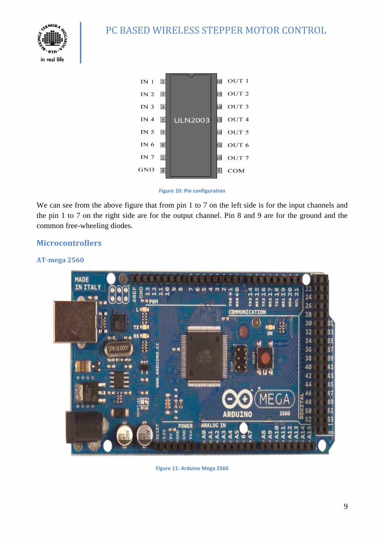
Figure 10: Pin configuration
We can see from the above figure that from pin 1 to 7 on the left side is for the input channels and
the pin 1 to 7 on the right side are for the output channel. Pin 8 and 9 are for the ground and the
common free-wheeling diodes.
Microcontrollers
AT-mega 2560
Figure 11: Arduino Mega 2560

PC BASED WIRELESS STEPPER MOTOR CONTROL
10
The Arduino Mega 2560 is a microcontoller board based on the ATMega 2560. It has 54 digital
input/output pins (of which 14 can be used as PWM outputs), 16 analoginputs, 4 UARTs (hardware
serial ports), a 16 MHz crystal oscillator, a USB connection, apower jack, an ICSP header, and a
reset button.
It contains everything needed to support the microcontroller; simply connect it to a
computer with a USB cable or power it with a AC-to-DC adapter or battery to get started. The
Mega is compatible with most shields designed for the Arduino Duemilanove or Diecimila.
AT-mega 328
Figure 12: ATmega 328
Arduino UNO is a microcontroller board based on the ATmega 328. We receive the
encoded signal from the receiver and forward it to the microcontroller ATmega328. But
microcontroller cannot directly receive the signal, so for this purpose we used Arduino UNO board.
Arduino has 14 pins which all can work as input/output pins. In these pins six pins can be use as
Pulse Width Modulation (PWM) outputs, 16MHz crystal oscillator, analog output, connection for
USB, reset button, power jack and ICSP header. Even it has all those things which we need to
support our microcontroller. It can be connect to computer simply via USB cable. Arduino UNO
board can be powered by AC to DC adapter. UNO board does not use FTDI USB to serial driver
chip, that’s why it is different from all other boards.
Arduino Board Communication
We use Arduino microcontroller because it has so many facilities to communicate with the
computer and the microcontroller. Arduino can communicate with other Arduino boards. ATmega
2560 provides 4 hardware UART TTL (5V) serial communications. Microcontroller ATmega328

PC BASED WIRELESS STEPPER MOTOR CONTROL
11
gives UART TTL serial communication with the help of digital pin 0 (Transmitter) and digital pin 0
(Receiver). On the board for serial communication through USB we have ATmega8U2 which
appears as virtual com port to software on the computer. There is no need to any external driver if
8U2 firmware uses the standard USB com driver.
The receiver and transmitter LEDs on the board flashes when the data is send through the USB
serial chip and through USB communication port of the computer. This is the Arduino serial
monitor, which allows data to transmit and receive from the Arduino board. One can use any digital
pin for serial communication by using software serial library.
Transmitter and Receiver
STT-433 RF transmitter
Figure 13: STT-433 RF transmitter
A perfect RF transmitter for low cost and long range is required for such experiment. Thus STT-433
RF transmitter is placed for transmitting the signal. It is an ideal transmitter for remote control
applications. It operates from a supply of 1.5 to 12 volts. It employs a SAW-stabilized oscillator,
ensuring accurate frequency control for best range performance.

PC BASED WIRELESS STEPPER MOTOR CONTROL
12
STT-433 RF Receiver
Figure 14: STR-433MHz Receiver
We used transmitter STT-433MHz in this project and now we are going to use the receiver the of
the same frequency which is RF STR-433MHz. STR-433MHz is very ideal for the short range
remote control application. It is low cost and does not need any external RF components except
antenna. It does not generate any emission virtually so it is under the law of FCC in USA and ETSI
in Europe.

PC BASED WIRELESS STEPPER MOTOR CONTROL
13
Chapter 3 DESIGN AND IMPLEMENTATION
PC (GUI)
Figure 15: GUI
As we explained in the beginning and our blocks diagram that the command will be sent from the
computer. In order to make it use friendly and so that everyone can use it. We make a Graphical
User Interface (GUI). In this GUI we have included all the four functions namely ‘Speed up’ ‘Speed
down’ ‘Clockwise’ ‘Anti clockwise’ of our project. In addition to that we put two other functions
‘Reset All’ and ‘Exit Application’. We have identified the main functions of our project are the
speed control and direction control. Speed can be controlled by increasing the speed or decreasing
the speed. As far as the direction control is concerned the direction can be either clockwise or Anti
clockwise. We fix the initial speed of the stepper motor. So the stepper motor starts with a fixed
initial speed. In order to increase the speed we click the speed up button. This will increase the
speed. We also put four LEDS on the receiver end. So whenever we click the speed up button with
the increase in the motion of the stepper motor the LEDS also start blinking fast. We must also
remind that the LEDS also blink with the initial speed as shown in the figure below. These leds are
connected to the motor controller on the receiver side.

PC BASED WIRELESS STEPPER MOTOR CONTROL
14
Figure 16: Motor driver with LEDS
We have added a separate block in the GUI to show the information about the participants and the
supervisors as shown in the GUI. There is another block where we have inserted the two functions
with a drop down menu. These drop-down menus are the port numbers and the Baud rate. There are
eight ports included in the drop-down menu as shown in the figure below.
Figure 17: Drop-down menu of port number
In the Baud rate drop-down menu we have added three rates. Among which our stepper motor is
running on 9600 as shown in the figure below. Baud is synonymous to symbols or pulses per

PC BASED WIRELESS STEPPER MOTOR CONTROL
15
second. Baud rate is also known as symbol rate. In other words Baud rate is known as data
transmission rate (bits/second).
Figure 18: Drop-down menu of Baud rate
In order to make this GUI we have used the programming language Visual Basic. A sample code
from the whole code is presented below. The whole code is added to the Appendix. As we can see
in the code below that the block set for the “Stepper Motor Speed Controller” has a background
color brown. The title of the block is set to “Stepper Motor Speed Controller”. The following lines
after setting the title for the block is about the different properties of the font like size, type etc. The
last six lines of the code before the end command are defining the color of the title and the size.
Begin VB.Label Label1
BackColor = &H000040C0&
Caption = "Stepper Motor Speed Controller"
BeginProperty Font
Name = "Impact"
Size = 35.25
Charset = 0
Weight = 400
Underline = 0 'False
Italic = -1 'True
Strikethrough = 0 'False
EndProperty
ForeColor = &H8000000E&
Height = 975
Left = 120
TabIndex = 3
Top = 120
Width = 9495
End
End

PC BASED WIRELESS STEPPER MOTOR CONTROL
16
The result of the above code is the block presented down here. So is the rest of the code for the rest
of the GUI defining different other blocks.
After clicking connect on the visual basic program the transmitter start by initializing the serial port
at Baud rate 9600 after that every time a user clicks on a command like (speed up, speed down,
clockwise, anti clockwise, reset all) the visual basic program send a signal represented in letters and
then the transmitter microprocessor reads the signals and assign for each letter a number that will be
sent to the receiver:

PC BASED WIRELESS STEPPER MOTOR CONTROL
17
In the receiver part we have created a Boolean that represents the motor direction and we have
created an integer that represents the stepper motor speed:
When receiving a signal from the transmitter which is represented in numbers the processors will
translate the signal and will act according to the translation which is actually a command chosen by
the user for example if the command was speed up the program will use an equation which is
speedlimit*2 :

PC BASED WIRELESS STEPPER MOTOR CONTROL
18
Transmitter side
AT-mega 2560
The different components in the motorcontroller has been defined in the figure below.
Figure 19: ATmega 2560 with defined components
Power pin description
We can see that there are following power pins:
Vin: this pin is used to power jack while using AC to DC external voltage.
5V: this 5V is, the power supply used to give to the microcontroller and other components, given by
a USB or Vin
3.3V: this amount of voltage is supplied from on board regulator. Maximum current draw is 50mA.
GND: simply ground pins.
Input and output
As we have described above that there are 54 input and output pins. All the pins can be used as
input or output on an operating voltage at 5V. They can provide and receive a maximum of 40mA.
They have an internal resistance of 20-50kOhms. Some of the pins have specialized functions as
follow:
Serial: 0 (RX) and 1 (TX); Serial 1: 19 (RX) and 18 (TX); Serial 2: 17 (RX) and 16 (TX); Serial 3:
15 (RX) and14 (TX). RX is used to receive and TX is used to transmit TTL data.

PC BASED WIRELESS STEPPER MOTOR CONTROL
19
External Interrupts: 2 (interrupt 0), 3 (interrupt 1), 18 (interrupt 5), 19 (interrupt 4), 20 (interrupt 3),
and 21 (interrupt 2). These pins can be configured to trigger an interrupt on a low value, a rising or
falling edge, or a change in value.
PWM: 0 to 13. 8-bit PWM output is provided with the “analogWrite()” function.
SPI: 50 (MISO), 51 (MOSI), 52 (SCK), 53 (SS). They have the ability to support SPI
communication.
LED: 13. As the name concludes itself that a built-in LED is connected to this pin 13.
I²C: 20 (SDA) and 21 (SCL). Pins 20 and 21 are used for I²C communication or TWI
communication.
STT-433 RF Transmitter
Figure 20: Mechanical Diagram of transmitter
Pin Description
ANT (Antenna): The resistance of the antenna is 50 ohm. And the impedance affects the harmonic
emissions and the output power. So for this purpose an LC low-pass filter is used to filter the
harmonic emissions. We use the single core wire with the length of about 17 cm.
VCC (Voltage): VCC is the required voltage for the operating of the transmitter. Two capacitors
should be used for degradation of the noise otherwise it will affect the transmitter performance.
DATA: The data pin get data from the encoder in our case we get encoded data from the
microprocessor.
GND (Ground): This is the transmitter ground connect to ground plane.
Operation:
On Off Keying (OOK) is a binary form of amplitude modulation. When logical “0” is being sent,
the transmitter is off, fully suppressing the carrier, and the transmitter current is very low less than

PC BASED WIRELESS STEPPER MOTOR CONTROL
20
1mA. When logical “1” is being sent the transmitter carrier is fully on and the module current at its
highest it’s about 11mA with 3V power supply.
On Off Keying is a method for modulation which is best choice for the remote control application
where power consumption and cost maters. When transmitter does not transmit data at that time no
power consume. So in our project transmitter STT-433 is better to use as compare to FSK
transmitters.
Schematic
Figure 21: Schematic for the transmitter side
Experemental Explanation:
We use ArduinoMega 2560 board in this project on which Atmega2560 microcontroller is fixed.
But for understanding easily i just showed the IC diagram and its connections.
As we explane before that we give instruction through the GUI (Graphical User Interface) to our
transmiter side via USB port. In the above figure 21. data comes from the USB port to
microcontroller Atmega 2560 pin number 12, which process data and forward it to encoder. In
Atmega2560 encoder is built in, so we dont need to connect separate encoder. Now this encoded
data is forward to transmitter STT-433MHz, where data pin recieves the data and modulate it.

PC BASED WIRELESS STEPPER MOTOR CONTROL
21
Further transmitter transmit data through the antenna, we use 20 cm wire as antenna in this project.
Microcontroller Atmega2560 also provide VCC and Ground to Transmiter STT-433MHz.
Receiver side
AT-mega 328
Figure 22: ATmega 328 with defined components
Power Pins Description
Vin: When applying external voltage AC to DC we use pin Vin to power jack.
5V: Arduino UNO board give 5V regulated power supply to microcontroller and to other
components. The voltage can be provided from either USB or from Vin.
3V3: The Arduino board can generate 3.3V supply from on board regulator and in this case 50mA
current draw is maximum.
GND: Ground pin.
Input and Output
There are 14 digital input output pins on Arduino UNO board in which any one can be use as input
or output pin and the operating voltage will be 5V. Every pin has internal pull up resisters of 20-
50kΩ and these resistors are disconnected by default. Each pin can provide or receives maximum of
40mA.

PC BASED WIRELESS STEPPER MOTOR CONTROL
22
Serial: 0(Rx) and Serial 1(Tx) This pin is use to receive and transmit TTL serial data and connect to
ATmega8U2 USB to TTL serial chip.
External Interrupts 2 and 3: These pins are triggering pins and configured to use for trigger an
interrupt on a low value, change in value a rising or falling edge.
Pulse Width Modulation: Pin 3, 5, 6, 9, 10 and 11 provide 8 bit PWM output.
SPI: Pin 10(SS), 11(MOSI),12(MISO), 13(SCK) support SPI communication. It is not included in
the Arduino programming language because it is provide by the underlying hardware.
LED: Pin 13 is connect to built in LED, it depends on the pin value if its value is low the LED is off
and when the value is high LED is on.
The Arduino board has 6 analog pins as input, by default the can measure from ground to 5V, every
analog pin provides 10 bits of resolution. If one want to change the upper range of the voltage he
can change it by using the AREF pin and the “analogRefrence()” function.
In Arduino UNO we have some specialized functional pins also.
I²C: 4(SDA) and 6(SCL). By using the wire library I²C (TWI) can communicate.
AREF and Reset are also special pins on the Arduino board.
RF Receiver
Figure 23: Pin configuration of receiver
Pin Description
ANT (Antenna): Receiver receives its input through the antenna.
GND (Ground): Receiver ground.
VCC: Pin VCC provides the operating voltage which is connect electrically. Here in this circuit one
can see that we have two VCC pins we can provide VCC to one pin or both pins. VCC should be
bypassed with .1µF ceramic capacitor.
DATA: This pin gives digital data which has received from the antenna and forwarded to decoder.
This is also CMOS compatible output.

PC BASED WIRELESS STEPPER MOTOR CONTROL
23
Operation
Super Regenerative AM Detection
Receiver STR-433MHz using super regenerative AM detector to demodulate the incoming AM
carrier. This detector has a positive feedback gain stage which is greater than “1” or unity so that it
oscillates. When the gain stage oscillates an RC time constant include gaining stage. And this gain
is lower over time proportional to the RC time constant until the oscillation dies, after the
oscillation stop or dies gaining stage decrease, and start charging the RC circuit which increases the
gain and oscillation begins again. So like this every time the oscillation of the gain stage turn off
and turned on and for this RC time constant sets the rate. This rate should super audible and it
should be lower than the original rate of oscillation. At the frequency of the main oscillation every
input RF signal will be add in restarting. Amplitude of the RF input is directly proportional to the
staying of the main oscillation period of time. This means that if amplitude of the input RF is
increases the main oscillation will stay for longer period of time with the higher emitter current.
That’s why it is easy to detect the real base-band signal by using ordinary low pass filtering emitter
current.
Data Slicer
The base band analog signal from the super regenerative detector converts by data slicer to TTL or
CMOS compatible output. Data slice is AC coupled with the audio output, because the data rate is
very less here. Maximum and minimum pulse width is always limited by the AC coupling. We
usually use non return to zero (NRZ) or pulse width modulation (PWM) to encode the data on the
transmitting side.
Those applications which uses the NRZ data encoding use microcontrollers, the common source of
NRZ data is UART which is built in microcontroller. In case of PWM the common source is a
remote control IC like HC-12E or ST14 CODEC (Sunrom technology).
Data is sending style is constant square wave. Normally for this square wave the duty cycle is 66%
for “1” or 33% for “0”. PWM encoded data is used in this receiver with data slicer but it functions
with NRZ if the specific rule follows.
Power Supply
The power consumption in this project is a primary concern so for this project the receiver STR-
433MHz is a best choice because it is specially designed for the low power consumption with 5V
power supply. Power supply is bypassed by two capacitors .1µF and .47µF ceramic and tantalum
respectively. It takes 750mSec to output valid data after powered.
Antenna Input
Different type of antennas can be use with the STR-433MHz and sometimes integrated printed
antennas and single core wire of about 17cm. Performance of the antenna is depend upon the type
of the antenna.

PC BASED WIRELESS STEPPER MOTOR CONTROL
24
Schematic
Figure 24: Schematic from the receiver side
Experimental Explanation
As you can see from the figure, receiver STR 433MHz receives the RF modulated signal from the
transmitter side. Receiver further forward data to Arduino UNO board via pin number “0”. We have
fixed the microcontroller ATmega328 on the Arduino UNO board and this microcontroller process
the data, execute the code and command to stepper motor driver through pin number “8”,”9”,”10”
and “11”.
Furthermore microcontroller ATmega328 provides VCC to receiver STR 433MHz and Stepper
motor driver. The figure also shows the Arduino UNO board and computer USB port
communication, which gives the required voltage to UNO board.
The figure shows the receiver part of the project with microcontroller ATmega328. We use
microcontroller with Arduino UNO board in the project which has shown in figure 25. Figure
shows that we get our modulated signal through antenna. For decoding and further processing
forward this signal to microcontroller ATmega328. The figure also shows VCC and Ground
connection to Stepper Motor driver.

PC BASED WIRELESS STEPPER MOTOR CONTROL
25
Figure 25: Another schematic for the receiver side

PC BASED WIRELESS STEPPER MOTOR CONTROL
26
CHAPTER 5: RESULTS AND CONCLUSION This project has been one of the most interesting and learning experience to all of us. We have used
our knowledge and previous experience to accomplish our goals. We have learned new ways of
testing our project. Following results can be concluded from this project;
1. Graphical User Interface is made in Visual Basic which is a powerful tool. This GUI could
have been made more efficient by making the borders invisible. Since it was not our major
concern, we make it simple and effective.
2. The microprocessor is receiving the signal with a delay. This delay can be minimized by
decreasing the transmitting time.
3. The signal is sent even blocking the signal by putting an obstacle in between the two sides
i.e transmitting and receiving sides.
4. All the requirements have been achieved.
5. The movements and of the motor in clockwise and anticlockwise directions are controlled in
a specified manner.
6. Some of attributes in speed and direction can also be controlled by some buttons on the
keyboard.
7. The direction and the speed can be viewed by attaching a weight at the end of the motor.
In the end we must say that it was a successful project and we did our best to make it as perfect as
possible.

PC BASED WIRELESS STEPPER MOTOR CONTROL
27
CHAPTER 6 DISCUSSION AND FUTURE WORK This project consists of three different parts namely the GUI, the physical equipment and its
connection to other parts and the programming of the microcontrollers. As far as the physical
equipments are concerned we have chosen the suitable equipments. The only equipment that can be
replaced with another is the antenna. The antenna that we have used is the handmade antenna which
has a very limited range and this range can be extended with the use of a good company made
antenna. Another development that can be made to extend the range is the use of a proper battery or
adapter instead of computer used as power source using USB cable.
The GUI can be made more attractive and professional by removing the borders
between different functionalities. Since we made it as a Bachelor project we made it as simple as
possible.
Another development that can be made in future to make this project more
professional is to make it usable for more than one stepper motor. One can make it so that there can
be an option in the programming to select one of the stepper motors if more than one motor is
attached at the receiving end.
Another development that can be made is that a digital display can be added to show
the speed of the motor. At the current moment we can only see the speed by the increase in the
movement of the speed. After the addition of the digital display one can see the actual speed of the
motor.
This project can be made as a more professional project if one can provide more time
and financial support.
PC BASED WIRELESS STEPPER MOTOR CONTROL
28
Appendix
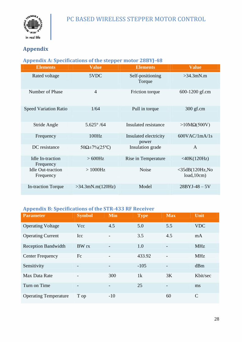
Appendix A: Specifications of the stepper motor 28BYJ-48
Elements Value Elements Value
Rated voltage 5VDC
Self-positioning
Torque
>34.3mN.m
Number of Phase 4 Friction torque 600-1200 gf.cm
Speed Variation Ratio 1/64
Pull in torque 300 gf.cm
Stride Angle 5.625° /64
Insulated resistance >10MΩ(500V)
Frequency 100Hz Insulated electricity
power
600VAC/1mA/1s
DC resistance 50Ω±7%(25)
Insulation grade A
Idle In-traction
Frequency
> 600Hz
Rise in Temperature <40K(120Hz)
Idle Out-traction
Frequency
> 1000Hz
Noise <35dB(120Hz,No
load,10cm)
In-traction Torque >34.3mN.m(120Hz)
Model 28BYJ-48 – 5V
Appendix B: Specifications of the STR-433 RF Receiver
Parameter Symbol Min Type Max Unit
Operating Voltage Vcc 4.5 5.0 5.5 VDC
Operating Current Icc - 3.5 4.5 mA
Reception Bandwidth BW rx - 1.0 - MHz
Center Frequency Fc - 433.92 - MHz
Sensitivity - - -105 - dBm
Max Data Rate - 300 1k 3K Kbit/sec
Turn on Time - - 25 - ms
Operating Temperature T op -10 60 C

PC BASED WIRELESS STEPPER MOTOR CONTROL
29
Appendix C: Specifications of the Microcontroller ATMega2560
Elements Value Elements Value
Operating Voltage 5V DC Current for 3.3V
Pin
50 mA
Input Voltage
(recommended)
7-12V Flash Memory 256 KB of which 8 KB
used by bootloader
Input Voltage (limits) 6-20V
SRAM 8 KB
Digital I/O Pins 54 (of which 14 provide
PWM output)
EEPROM 4 KB
Analog Input Pins 16 Clock Speed 16 MHz
DC Current per I/O Pin 40 mA
Appendix D: Specifications of STT-433 RF Transmitter
Parameters Symbols Min Ty Max Unit
Operating
Voltage
Vcc 1.5 3.0 12 Volts
DC
Operating
Current
Data = VCC
Icc - 11mA @3V
59mA @5V
- mA
Operating
Current
Data = GND
Icc - 100 - uA
Frequency
Accuracy
TOL fc -75 0 +75 Khz
Center
Frequency
Fc - 433 - Mhz
RF Output
Power
- 4 dBM@3V (2 mW)
16 dBM@5V (39 mW)
dBm /
mW
Data Rate 200 1K 3K BPS
Temperature -20 +60 Deg. C
Power up delay 20 ms

PC BASED WIRELESS STEPPER MOTOR CONTROL
30
Appendix E: Code for Visual Basic VERSION 5.00
Object = "648A5603-2C6E-101B-82B6-000000000014#1.1#0"; "MSCOMM32.OCX"
Begin VB.Form Form1
Caption = "Stepper MOTOR SPEED & Direction CONTROL"
ClientHeight = 8835
ClientLeft = 60
ClientTop = 450
ClientWidth = 9795
LinkTopic = "Form1"
ScaleHeight = 8835
ScaleWidth = 9795
StartUpPosition = 3 'Windows Default
Begin VB.CommandButton Command7
BackColor = &H000000C0&
Caption = "Reset ALL"
BeginProperty Font
Name = "MS Sans Serif"
Size = 12
Charset = 0
Weight = 700
Underline = 0 'False
Italic = 0 'False
Strikethrough = 0 'False
EndProperty
Height = 1095
Left = 4320
MaskColor = &H00FFFFFF&
Style = 1 'Graphical
TabIndex = 23
Top = 7560
Width = 1935
End
Begin VB.CommandButton Command3
BackColor = &H000080FF&
Caption = "Speed Down"
BeginProperty Font
Name = "MS Sans Serif"
Size = 18
Charset = 0
Weight = 700
Underline = 0 'False
Italic = 0 'False
Strikethrough = 0 'False
EndProperty
Height = 1695
Left = 7080
Style = 1 'Graphical
TabIndex = 16
Top = 2880
Width = 2295
End
Begin VB.CommandButton Command1
BackColor = &H000080FF&
Caption = "Speed UP"
BeginProperty Font

PC BASED WIRELESS STEPPER MOTOR CONTROL
31
Name = "MS Sans Serif"
Size = 18
Charset = 0
Weight = 700
Underline = 0 'False
Italic = 0 'False
Strikethrough = 0 'False
EndProperty
Height = 1695
Left = 4560
Style = 1 'Graphical
TabIndex = 15
Top = 2880
Width = 2295
End
Begin VB.Frame Frame3
BackColor = &H00E0E0E0&
Caption = "Speed Control"
BeginProperty Font
Name = "MS Sans Serif"
Size = 13.5
Charset = 0
Weight = 700
Underline = 0 'False
Italic = 0 'False
Strikethrough = 0 'False
EndProperty
ForeColor = &H8000000D&
Height = 2535
Left = 4320
TabIndex = 17
Top = 2280
Width = 5295
End
Begin VB.Frame Frame1
BackColor = &H0080C0FF&
Height = 3615
Left = 120
TabIndex = 8
Top = 1200
Width = 4095
Begin VB.Label Label6
BackColor = &H00000000&
BackStyle = 0 'Transparent
Caption = "Prof. Sven Johansson"
BeginProperty Font
Name = "MS Sans Serif"
Size = 13.5
Charset = 0
Weight = 700
Underline = 0 'False
Italic = 0 'False
Strikethrough = 0 'False
EndProperty
ForeColor = &H00800000&
Height = 375

PC BASED WIRELESS STEPPER MOTOR CONTROL
32
Index = 1
Left = 960
TabIndex = 24
Top = 960
Width = 2775
End
Begin VB.Label Label9
BackColor = &H00000000&
BackStyle = 0 'Transparent
Caption = "SHAHNAWAZ KHAN"
BeginProperty Font
Name = "MS Sans Serif"
Size = 13.5
Charset = 0
Weight = 700
Underline = 0 'False
Italic = 0 'False
Strikethrough = 0 'False
EndProperty
ForeColor = &H00800000&
Height = 375
Left = 960
TabIndex = 14
Top = 2880
Width = 3135
End
Begin VB.Label Label8
BackColor = &H00000000&
BackStyle = 0 'Transparent
Caption = "ZAINULABIDEEN"
BeginProperty Font
Name = "MS Sans Serif"
Size = 13.5
Charset = 0
Weight = 700
Underline = 0 'False
Italic = 0 'False
Strikethrough = 0 'False
EndProperty
ForeColor = &H00800000&
Height = 375
Left = 960
TabIndex = 13
Top = 2400
Width = 2775
End
Begin VB.Label Label7
BackColor = &H00000000&
BackStyle = 0 'Transparent
Caption = "OMAR JAMAL"
BeginProperty Font
Name = "MS Sans Serif"
Size = 13.5
Charset = 0
Weight = 700
Underline = 0 'False

PC BASED WIRELESS STEPPER MOTOR CONTROL
33
Italic = 0 'False
Strikethrough = 0 'False
EndProperty
ForeColor = &H00800000&
Height = 375
Left = 960
TabIndex = 12
Top = 1920
Width = 2775
End
Begin VB.Label Label6
BackColor = &H00000000&
BackStyle = 0 'Transparent
Caption = "Prof. Erik Loxbo"
BeginProperty Font
Name = "MS Sans Serif"
Size = 13.5
Charset = 0
Weight = 700
Underline = 0 'False
Italic = 0 'False
Strikethrough = 0 'False
EndProperty
ForeColor = &H00800000&
Height = 375
Index = 0
Left = 960
TabIndex = 11
Top = 600
Width = 2775
End
Begin VB.Label Label3
BackColor = &H00000000&
BackStyle = 0 'Transparent
Caption = "Group Members:"
BeginProperty Font
Name = "MS Sans Serif"
Size = 13.5
Charset = 0
Weight = 700
Underline = 0 'False
Italic = 0 'False
Strikethrough = 0 'False
EndProperty
Height = 375
Left = 120
TabIndex = 10
Top = 1440
Width = 2415
End
Begin VB.Label Label2
BackColor = &H00000000&
BackStyle = 0 'Transparent
Caption = "Supervisors:"
BeginProperty Font
Name = "MS Sans Serif"

PC BASED WIRELESS STEPPER MOTOR CONTROL
34
Size = 13.5
Charset = 0
Weight = 700
Underline = 0 'False
Italic = 0 'False
Strikethrough = 0 'False
EndProperty
Height = 375
Left = 120
TabIndex = 9
Top = 240
Width = 1575
End
End
Begin VB.CommandButton Command5
BackColor = &H0000C000&
Caption = "Exit Application"
BeginProperty Font
Name = "MS Sans Serif"
Size = 18
Charset = 0
Weight = 700
Underline = 0 'False
Italic = 0 'False
Strikethrough = 0 'False
EndProperty
Height = 1095
Left = 6360
MaskColor = &H000080FF&
Style = 1 'Graphical
TabIndex = 7
Top = 7560
UseMaskColor = -1 'True
Width = 3255
End
Begin VB.Frame Frame2
BackColor = &H80000011&
Caption = "Connect To Serial"
BeginProperty Font
Name = "MS Sans Serif"
Size = 13.5
Charset = 0
Weight = 700
Underline = 0 'False
Italic = 0 'False
Strikethrough = 0 'False
EndProperty
ForeColor = &H000000FF&
Height = 3735
Left = 120
TabIndex = 0
Top = 4920
Width = 4095
Begin MSCommLib.MSComm MSComm1
Left = 0
Top = 3000

PC BASED WIRELESS STEPPER MOTOR CONTROL
35
_ExtentX = 1005
_ExtentY = 1005
_Version = 393216
DTREnable = -1 'True
End
Begin VB.CommandButton Command2
Caption = "Connect"
BeginProperty Font
Name = "MS Sans Serif"
Size = 18
Charset = 0
Weight = 700
Underline = 0 'False
Italic = 0 'False
Strikethrough = 0 'False
EndProperty
Height = 975
Left = 480
TabIndex = 6
Top = 2520
Width = 3375
End
Begin VB.ComboBox Combo3
BeginProperty Font
Name = "MS Sans Serif"
Size = 24
Charset = 0
Weight = 700
Underline = 0 'False
Italic = 0 'False
Strikethrough = 0 'False
EndProperty
Height = 675
ItemData = "Stepper Motor Speed Control.frx":0000
Left = 2280
List = "Stepper Motor Speed Control.frx":000D
TabIndex = 5
Text = "2400"
Top = 1560
Width = 1575
End
Begin VB.ComboBox Combo2
BeginProperty Font
Name = "MS Sans Serif"
Size = 24
Charset = 0
Weight = 700
Underline = 0 'False
Italic = 0 'False
Strikethrough = 0 'False
EndProperty
Height = 675
ItemData = "Stepper Motor Speed Control.frx":0023
Left = 2520
List = "Stepper Motor Speed Control.frx":0025
TabIndex = 4

PC BASED WIRELESS STEPPER MOTOR CONTROL
36
Text = "1"
Top = 720
Width = 1335
End
Begin VB.Label Label5
AutoSize = -1 'True
BackStyle = 0 'Transparent
Caption = "BAUD RATE"
BeginProperty Font
Name = "MS Sans Serif"
Size = 13.5
Charset = 0
Weight = 700
Underline = 0 'False
Italic = 0 'False
Strikethrough = 0 'False
EndProperty
ForeColor = &H00404080&
Height = 360
Left = 120
TabIndex = 2
Top = 1800
Width = 1755
End
Begin VB.Label Label4
AutoSize = -1 'True
BackStyle = 0 'Transparent
Caption = "Port Number"
BeginProperty Font
Name = "MS Sans Serif"
Size = 13.5
Charset = 0
Weight = 700
Underline = 0 'False
Italic = 0 'False
Strikethrough = 0 'False
EndProperty
ForeColor = &H00404080&
Height = 360
Left = 120
TabIndex = 1
Top = 840
Width = 1785
End
End
Begin VB.CommandButton Command4
BackColor = &H000040C0&
Caption = "Clockwise"
BeginProperty Font
Name = "MS Sans Serif"
Size = 18
Charset = 0
Weight = 700
Underline = 0 'False
Italic = 0 'False
Strikethrough = 0 'False

PC BASED WIRELESS STEPPER MOTOR CONTROL
37
EndProperty
Height = 1695
Left = 4560
Style = 1 'Graphical
TabIndex = 18
Top = 5640
Width = 2295
End
Begin VB.CommandButton Command6
BackColor = &H000040C0&
Caption = "Anti Clockwise"
BeginProperty Font
Name = "MS Sans Serif"
Size = 18
Charset = 0
Weight = 700
Underline = 0 'False
Italic = 0 'False
Strikethrough = 0 'False
EndProperty
Height = 1695
Left = 7080
Style = 1 'Graphical
TabIndex = 19
Top = 5640
Width = 2295
End
Begin VB.Frame Frame4
BackColor = &H00E0E0E0&
Caption = "Direction Control"
BeginProperty Font
Name = "MS Sans Serif"
Size = 13.5
Charset = 0
Weight = 700
Underline = 0 'False
Italic = 0 'False
Strikethrough = 0 'False
EndProperty
ForeColor = &H8000000D&
Height = 2535
Left = 4320
TabIndex = 20
Top = 4920
Width = 5295
End
Begin VB.Label Label12
BackColor = &H00008000&
Caption = "Blekinge Institute of Technology"
BeginProperty Font
Name = "Tahoma"
Size = 15.75
Charset = 0
Weight = 700
Underline = 0 'False
Italic = 0 'False

PC BASED WIRELESS STEPPER MOTOR CONTROL
38
Strikethrough = 0 'False
EndProperty
Height = 495
Left = 4320
TabIndex = 22
Top = 1680
Width = 5295
End
Begin VB.Label Label11
BackColor = &H00008000&
Caption = "School of Engineering"
BeginProperty Font
Name = "Tahoma"
Size = 18
Charset = 0
Weight = 700
Underline = 0 'False
Italic = 0 'False
Strikethrough = 0 'False
EndProperty
Height = 495
Left = 4320
TabIndex = 21
Top = 1200
Width = 5295
End
Begin VB.Label Label1
BackColor = &H000040C0&
Caption = "Stepper Motor Speed Controller"
BeginProperty Font
Name = "Impact"
Size = 35.25
Charset = 0
Weight = 400
Underline = 0 'False
Italic = -1 'True
Strikethrough = 0 'False
EndProperty
ForeColor = &H8000000E&
Height = 975
Left = 120
TabIndex = 3
Top = 120
Width = 9495
End
End
Attribute VB_Name = "Form1"
Attribute VB_GlobalNameSpace = False
Attribute VB_Creatable = False
Attribute VB_PredeclaredId = True
Attribute VB_Exposed = False
Private Sub Command1_Click()
MSComm1.Output = "W"
'MSComm1.Output = vbCrLf
End Sub

PC BASED WIRELESS STEPPER MOTOR CONTROL
39
Private Sub Command2_Click()
On Error Resume Next
If Command2.Caption = "Connect" Then
MSComm1.CommPort = Combo2.Text
'MSComm1.CommPort = "7"
MSComm1.Settings = Combo3.Text & ",n,8,1"
'MSComm1.Settings = "9600,n,8,1"
MSComm1.PortOpen = True
Command2.Caption = "Disconnect"
Else
MSComm1.PortOpen = False
Command2.Caption = "Connect"
End If
End Sub
Private Sub Command3_Click()
MSComm1.Output = "S"
'MSComm1.Output = vbCrLf
End Sub
Private Sub Command4_Click()
MSComm1.Output = "D"
'MSComm1.Output = vbCrLf
End Sub
Private Sub Command5_Click()
Unload Form1
End Sub
Private Sub Command6_Click()
MSComm1.Output = "A"
'MSComm1.Output = vbCrLf
End Sub
Private Sub Command7_Click()
MSComm1.Output = "R"
'MSComm1.Output = vbCrLf
End Sub
Private Sub Form_Load()
Dim a As Integer
a = 1
While a < 9
Combo2.AddItem a, a - 1
a = a + 1
Wend
End Sub

PC BASED WIRELESS STEPPER MOTOR CONTROL
40
Appendix F: Code for microprocessor on Receiver side
#define RECEIVER
int freq=500; // speed in frequency
int motorPins[] = 8, 9, 10, 11;// stepper motor control pins
int count = 0; // for motor drive
int count2 = 0; // for motor drive
int speedLimit=32; // speed limit
unsigned int rfData; // data received from RF
// motor direction true=clockwise, false=anticlockwise
boolean stepperDirection = false;
// whether the string is complete
boolean stringComplete = false;
// Pin 13 has an LED connected on most Arduino board
int led = 13;
void setup()
// initialize serial:
Serial.begin(600);
// initialize the digital pin as an output.
pinMode(led, OUTPUT);
// motor control pin initiallizaion
for (count = 0; count < 4; count++)
pinMode(motorPins[count], OUTPUT);
//set timer 1 interuppt
cli(); // stop all interuppts

PC BASED WIRELESS STEPPER MOTOR CONTROL
41
TCCR1A=0; // set entire register to 0
TCCR1B=0; // set entire register to 0
TCNT1=0; // initialize counter value to zero
OCR1A=(156624/speedLimit);//((1000000)/(1024*freq))-1; // initial value is 15624> for 1Hz
TCCR1B|=(1<<WGM12); // turn on ctc mode
TCCR1B|=(1<<CS12)|(1<<CS10); //set CS12 and CS10 to 1 to set prescaller 1024
TIMSK1|=(1<<OCIE1A); //enable timer compare interuppt
sei(); // enable global interrupt flag
void loop()
// print the string when a newline arrives:
rfData=readUInt(true); // blocking function which will wait for any data from RF
//if(rfData==290) blink(5);
//speed control
if(rfData==280)
blink(1); // Blink Led one time
stepperDirection=true; // anticlockwise direciton
else if(rfData==281)
blink(2); // Blink Led two times
stepperDirection=false; // clockwise direciton
else if(rfData==282)
blink(3); // Blink Led three times
if(speedLimit<2048) speedLimit=speedLimit*2;

PC BASED WIRELESS STEPPER MOTOR CONTROL
42
stringComplete = true;
else if(rfData==283)
blink(4); // Blink Led four times
if(speedLimit>4) speedLimit=speedLimit/2;
stringComplete = true;
else if(rfData==284)
blink(5); // Blink Led four times
speedLimit=32;
stepperDirection = false;
stringComplete = true;
if(stringComplete)
OCR1A=(156624/speedLimit);
stringComplete = false;
// timer 1 interuppt service routine
ISR(TIMER1_COMPA_vect)
if ((count2 == 0) || (count2 == 1))
count2 = 16;
count2>>=1;

PC BASED WIRELESS STEPPER MOTOR CONTROL
43
if(stepperDirection==false)
for (count = 3; count >= 0; count--)
digitalWrite(motorPins[3 - count], count2>>count&0x01);
else if(stepperDirection)
for (count = 3; count >= 0; count--)
digitalWrite(motorPins[count], count2>>count&0x01);
/*void serialEvent()
while (Serial.available())
// get the new byte:
char inChar = (char)Serial.read();
// add it to the inputString:
inputString += inChar;
// if the incoming character is a newline, set a flag
// so the main loop can do something about it:
if (inChar == '\n')
stringComplete = true;
*/

PC BASED WIRELESS STEPPER MOTOR CONTROL
44
// Blink the LED:
void blink(int howManyTimes)
int i;
for (i=0; i< howManyTimes; i++)
digitalWrite(led, HIGH);
delay(300);
digitalWrite(led, LOW);
delay(300);

PC BASED WIRELESS STEPPER MOTOR CONTROL
45
Appendix G: Code for microprocessor on Transmitter side #define TRANSMITTER
// Pin 13 has an LED connected on most Arduino board
int led = 13;
void setup()
// initialize serial port to connect to PC at 9600 Baud Rate
Serial.begin(9600);
// Hardware supports up to 2400, but 1200 gives longer range
Serial1.begin(600);
void loop()
// read from port 0, send to port 1:
if (Serial.available())
char inByte = Serial.read();
// Put any number you want to send here
if(inByte=='a'||inByte=='A') // anticlockwise direciton
writeUInt(280);
blink(2);
else if(inByte=='d'||inByte=='D') // clockwise direciton
writeUInt(281);
blink(3);
else if(inByte=='w'||inByte=='W') // Speed Up
writeUInt(282);

PC BASED WIRELESS STEPPER MOTOR CONTROL
46
blink(4);
else if(inByte=='s'||inByte=='S') // Speed Down
writeUInt(283);
blink(5);
else if(inByte=='r'||inByte=='R') // Reset all
writeUInt(284);
blink(6);
// Blink the LED:
void blink(int howManyTimes)
int i;
for (i=0; i< howManyTimes; i++)
digitalWrite(led, HIGH);
delay(500);
digitalWrite(led, LOW);
delay(500);

PC BASED WIRELESS STEPPER MOTOR CONTROL
47
References:
1. http://en.wikipedia.org/wiki/Stepper_motor, Aug. 2012.
2. http://www.kiatronics.com/28byj-48-stepper-motor-5vdc-code-70289.html, Sep. 2012.
3. http://en.wikipedia.org/wiki/Commutator_%28electric%29, Aug. 2012.
4. http://homepage.cs.uiowa.edu/~jones/step/, Sep. 2012.
5. www.DatasheetCatalog.com, Nov. 2012.
6. http://www.engineersgarage.com/electronic-components/uln2003-datasheet, Nov. 2012.
7. http://www.4tronix.co.uk/arduino/Stepper-Motors.php, Oct. 2012.