pc-programmable temperature transmitters - gilson · pdf file• loop test fixed output for...
TRANSCRIPT

TRY & TRXPC-Programmable
Temperature Transmitters
April 2005 Data Sheet 3.95
Page 1
Isolated,Scaleable4-20mA
2-Wire(Loop-Powered)
RTDThermocouple
MillivoltsResistance
PotentiometerComplete,Read-to-InstallTemperatureAssembliesAvailable
Available in a variety of housing styles, the TRY andTRX are ready to install in the control room, in existinghardware, or in their own, complete temperatureassembly.
Features• Universal plant standard. No need to specify
and stock fixed range transmitters as spares.The TRY and TRX provide programmable inputtype and output scaling.
• PC-programmable with Windows® software.From a single screen, you can choose, and thenview to confirm, all of your application-specificoperating parameters from a personal computer.
• Fast measurement cycle. Delivering an outputupdate up to 8 times per second, thesetransmitters are twice as fast as comparablemicroprocessor-based instruments.
• Enhanced configuration software. Now triminput sensor readings, and customize inputlinearization curves for even greater accuracy.Program output damping to compensate forerratic sensor readings. Use the ConfigurationProgram to calibrate other loop instruments withits innovative Loop Test function.
DescriptionMoore Industries’ PC-ProgrammableTemperature Transmitters–the TRY (isolated) and TRX(non-isolated)–combine smart digital technology withadvanced analog operation to deliver superior reliabil-ity, accuracy and ease of use.
Now with even more flexible capabilities, these 2-wire (loop-powered) analog/digital hybrid trans-mittersprogram in a minute or less to accept direct inputsfrom:
• 23 RTD Types(2-, 3-, and 4-wire; Pt, Cu and Ni;10 to 1000 ohms)
• 9 Thermocouple Types(J, K, E, T, R, S, B, N, and C)
• Direct Millivolt Sources(-50 to 1000mV)
• Resistance & Potentiometer Devices(0 to 4000 ohms)
They convert the input to a highly accurate 4-20mAoutput that is both linear and scaleable with respectto the input–ready for direct interface with readoutinstruments, recorders, DCSs, and other computer-based SCADA systems.
Figure 1. Compact yet powerful, the 2-wire TRY and TRXtransmitters afford full programmability in a rugged, ready-to-install assembly.
All product names are registered trademarks of their respective companies.
Certifications
© 2005 Moore Industries-International, Inc.235-710-01N
Long Term
Stability
Page 2
TRY & TRXPC-ProgrammableTemperature Transmitters
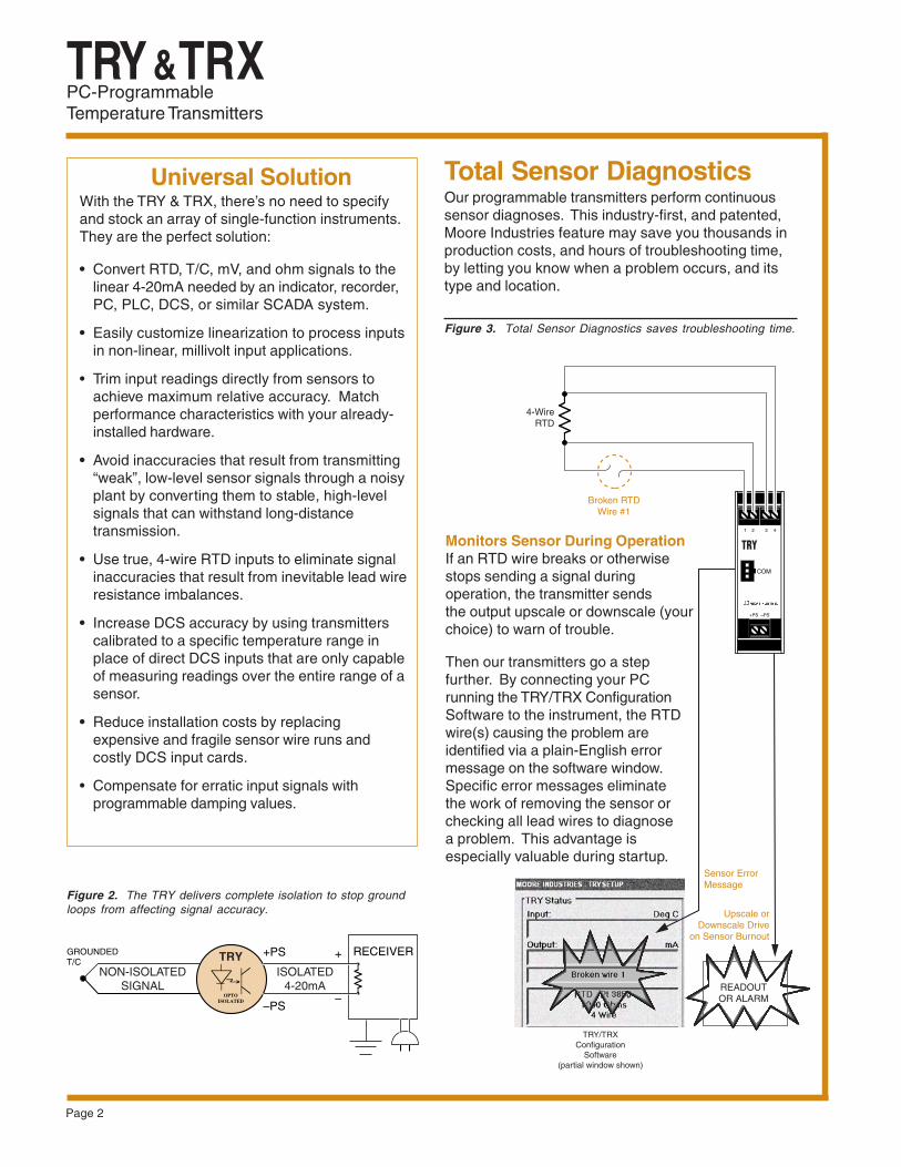
Total Sensor DiagnosticsOur programmable transmitters perform continuoussensor diagnoses. This industry-first, and patented,Moore Industries feature may save you thousands inproduction costs, and hours of troubleshooting time,by letting you know when a problem occurs, and itstype and location.
Figure 2. The TRY delivers complete isolation to stop groundloops from affecting signal accuracy.
Figure 3. Total Sensor Diagnostics saves troubleshooting time.
Monitors Sensor During OperationIf an RTD wire breaks or otherwisestops sending a signal duringoperation, the transmitter sendsthe output upscale or downscale (yourchoice) to warn of trouble.
Then our transmitters go a stepfurther. By connecting your PCrunning the TRY/TRX ConfigurationSoftware to the instrument, the RTDwire(s) causing the problem areidentified via a plain-English errormessage on the software window.Specific error messages eliminatethe work of removing the sensor orchecking all lead wires to diagnosea problem. This advantage isespecially valuable during startup.
Universal SolutionWith the TRY & TRX, there’s no need to specifyand stock an array of single-function instruments.They are the perfect solution:
• Convert RTD, T/C, mV, and ohm signals to thelinear 4-20mA needed by an indicator, recorder,PC, PLC, DCS, or similar SCADA system.
• Easily customize linearization to process inputsin non-linear, millivolt input applications.
• Trim input readings directly from sensors toachieve maximum relative accuracy. Matchperformance characteristics with your already-installed hardware.
• Avoid inaccuracies that result from transmitting“weak”, low-level sensor signals through a noisyplant by converting them to stable, high-levelsignals that can withstand long-distancetransmission.
• Use true, 4-wire RTD inputs to eliminate signalinaccuracies that result from inevitable lead wireresistance imbalances.
• Increase DCS accuracy by using transmitterscalibrated to a specific temperature range inplace of direct DCS inputs that are only capableof measuring readings over the entire range of asensor.
• Reduce installation costs by replacingexpensive and fragile sensor wire runs andcostly DCS input cards.
• Compensate for erratic input signals withprogrammable damping values.
READOUTOR ALARM
4-WireRTD
Broken RTDWire #1
Sensor ErrorMessage
1 2 3 4
+PS –PS
TRY/TRXConfiguration
Software(partial window shown)
Upscale orDownscale Drive
on Sensor Burnout
RECEIVER
–PS
+PS +
–OPTOISOLATED
GROUNDEDT/C
NON-ISOLATEDSIGNAL
ISOLATED4-20mA
TRY
Page 3
TRY & TRXPC-Programmable
Temperature Transmitters
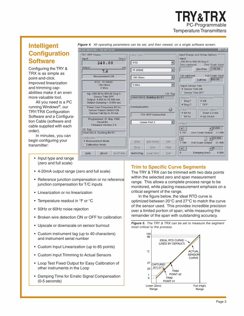
Figure 4. All operating parameters can be set, and then viewed, on a single software screen.
Trim to Specific Curve SegmentsThe TRY & TRX can be trimmed with two data pointswithin the selected zero and span measurementrange. This allows a complete process range to bemonitored, while placing measurement emphasis on acritical segment of the range.
In the figure below, the ideal RTD curve isoptimized between 20°C and 27°C to match the curveof the sensor used. This provides incredible precisionover a limited portion of span, while measuring theremainder of the span with outstanding accuracy.
Figure 5. The TRY & TRX can be set to measure the segmentmost critical to the process.
Lower (Zero)Range
Full (High)Range
IDEAL RTD CURVE(USED BY DEFAULT)
ACTUALSENSORCURVE
10098
10
˚C
TRIMPOINT #2
TRIMPOINT #1
27
20
CAPTURED20˚C-27˚C
IntelligentConfigurationSoftwareConfiguring the TRY &TRX is as simple aspoint-and-click.Improved linearizationand trimming cap-abilities make it an evenmore valuable tool.
All you need is a PCrunning Windows®, ourTRY/TRX ConfigurationSoftware and a Configura-tion Cable (software andcable supplied with eachorder).
In minutes, you canbegin configuring yourtransmitter:
• Input type and range(zero and full scale)
• 4-20mA output range (zero and full scale)
• Reference junction compensation or no referencejunction compensation for T/C inputs
• Linearization or no linearization
• Temperature readout in °F or °C
• 50Hz or 60Hz noise rejection
• Broken wire detection ON or OFF for calibration
• Upscale or downscale on sensor burnout
• Custom instrument tag (up to 40 characters)and instrument serial number
• Custom Input Linearization (up to 85 points)
• Custom Input Trimming to Actual Sensors
• Loop Test Fixed Output for Easy Calibration ofother instruments in the Loop
• Damping Time for Erratic Signal Compensation(0-5 seconds)
Page 4
TRY & TRXPC-ProgrammableTemperature Transmitters
Specifications and information subject to change without notice.
Factory Mutual ApprovalsIntrinsically Safe – HPP:Class I, II, III, Division 1, Groups A, B, C, D, E, F, GNon-Incendive – HPP:Class I, Division 2, Groups A, B, C, DSuitable for:Class II, Division 2, Groups F and GClass III, Division 2
Explosion/Dust Ignition-Proof‡ – [HPP in LH2]:Class I, Division 1, Groups A*, B, C, D
Class II and III, Division 1, Groups E, F, GT6@60°C Maximum Ambient; NEMA 4X; IP66
Canadian Standards Association (CSA)Intrinsically Safe – HPP:Class I, Divison 1, Groups A, B, C, DNon-Incendive – HPP:Class I, Division 2, Groups A, B, C, DGeneral (Ordinary) Location – DIN/HPP
European/ATEX 94/9/EC Directive Approvals:ISSeP Flame-Proof Apparatus – [HPP in LH2]
II 2GD EEx d IIC T6, IP66
LCIE Intrinsically Safe Apparatus – [HPP] II 2G EEx ib IIB/IIC T6@60°C
TestSafe Flame-Proof Approvals – [HPP in LH2]Ex d IIC; T6@60°C
CE Conformant – EMC Directive 89/336/EECEN 61326
Certifications
* For Group A only, all conduits must be sealed within 18 inches‡ 60°C (140°F) Maximum Ambient Temperature
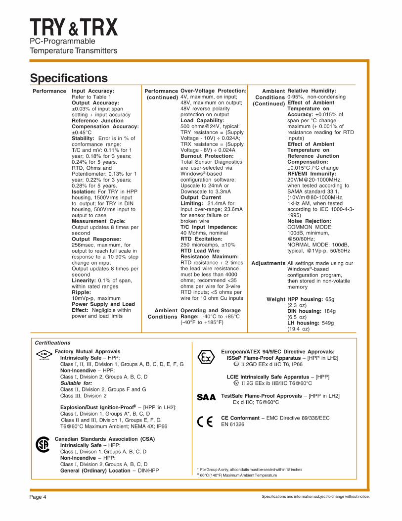
SpecificationsInput Accuracy:Refer to Table 1Output Accuracy:±0.03% of input spansetting + input accuracyReference JunctionCompensation Accuracy:±0.45°CStability: Error is in % ofconformance range:T/C and mV: 0.11% for 1year; 0.18% for 3 years;0.24% for 5 years.RTD, Ohms andPotentiometer: 0.13% for 1year; 0.22% for 3 years;0.28% for 5 years.Isolation: For TRY in HPPhousing, 1500Vrms inputto output; for TRY in DINhousing, 500Vrms input tooutput to caseMeasurement Cycle:Output updates 8 times persecondOutput Response:256msec, maximum, foroutput to reach full scale inresponse to a 10-90% stepchange on inputOutput updates 8 times persecondLinearity: 0.1% of span,within rated rangesRipple:10mVp-p, maximumPower Supply and LoadEffect: Negligible withinpower and load limits
Over-Voltage Protection:4V, maximum, on input;48V, maximum on output;48V reverse polarityprotection on outputLoad Capability:500 ohms@24V, typical:TRY resistance = (SupplyVoltage - 10V) ÷ 0.024A;TRX resistance = (SupplyVoltage - 8V) ÷ 0.024ABurnout Protection:Total Sensor Diagnosticsare user-selected viaWindows®-basedconfiguration software;Upscale to 24mA orDownscale to 3.3mAOutput CurrentLimiting: 21.4mA forinput over-range; 23.6mAfor sensor failure orbroken wireT/C Input Impedence:40 Mohms, nominalRTD Excitation:250 microamps, ±10%RTD Lead WireResistance Maximum:RTD resistance + 2 timesthe lead wire resistancemust be less than 4000ohms; recommend <35ohms per wire for 3-wireRTD inputs; <5 ohms perwire for 10 ohm Cu inputs
Operating and StorageRange: -40°C to +85°C(-40°F to +185°F)
Relative Humidity:0-95%, non-condensingEffect of AmbientTemperature onAccuracy: ±0.015% ofspan per °C change,maximum (+ 0.001% ofresistance reading for RTDinputs)Effect of AmbientTemperature onReference JunctionCompensation:±0.015°C /°C changeRFI/EMI Immunity:20V/M@20-1000MHz,when tested according toSAMA standard 33.1.(10V/m@80-1000MHz,1kHz AM, when testedaccording to IEC 1000-4-3-1995)Noise Rejection:COMMON MODE:100dB, minimum,@50/60Hz;NORMAL MODE: 100dB,typical, @1Vp-p, 50/60Hz
All settings made using ourWindows®-basedconfiguration program,then stored in non-volatilememory
HPP housing: 65g(2.3 oz)DIN housing: 184g(6.5 oz)LH housing: 549g(19.4 oz)
Performance AmbientConditions
(Continued)
Weight
Performance(continued)
AmbientConditions
Adjustments
Page 5
TRY & TRXPC-Programmable
Temperature Transmitters
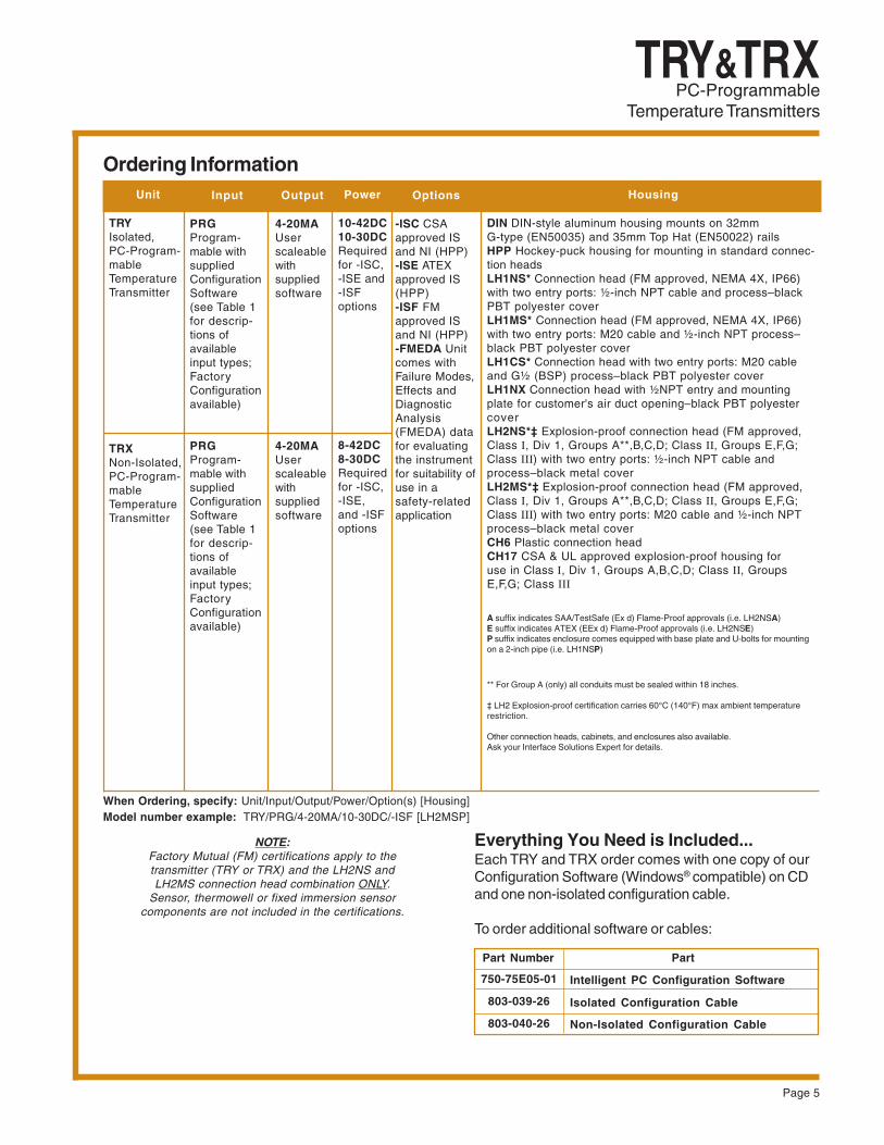
Ordering Information
NOTE:Factory Mutual (FM) certifications apply to thetransmitter (TRY or TRX) and the LH2NS andLH2MS connection head combination ONLY.
Sensor, thermowell or fixed immersion sensorcomponents are not included in the certifications.
Unit
TRYIsolated,PC-Program-mableTemperatureTransmitter
TRXNon-Isolated,PC-Program-mableTemperatureTransmitter
Input
PRGProgram-mable withsuppliedConfigurationSoftware(see Table 1for descrip-tions ofavailableinput types;FactoryConfigurationavailable)
PRGProgram-mable withsuppliedConfigurationSoftware(see Table 1for descrip-tions ofavailableinput types;FactoryConfigurationavailable)
Output
4-20MAUserscaleablewithsuppliedsoftware
4-20MAUserscaleablewithsuppliedsoftware
Options
-ISC CSAapproved ISand NI (HPP)-ISE ATEXapproved IS(HPP)-ISF FMapproved ISand NI (HPP)-FMEDA Unitcomes withFailure Modes,Effects andDiagnosticAnalysis(FMEDA) datafor evaluatingthe instrumentfor suitability ofuse in asafety-relatedapplication
Power
10-42DC10-30DCRequiredfor -ISC,-ISE and-ISFoptions
8-42DC8-30DCRequiredfor -ISC,-ISE,and -ISFoptions
Housing
DIN DIN-style aluminum housing mounts on 32mmG-type (EN50035) and 35mm Top Hat (EN50022) railsHPP Hockey-puck housing for mounting in standard connec-tion headsLH1NS* Connection head (FM approved, NEMA 4X, IP66)with two entry ports: ½-inch NPT cable and process–blackPBT polyester coverLH1MS* Connection head (FM approved, NEMA 4X, IP66)with two entry ports: M20 cable and ½-inch NPT process–black PBT polyester coverLH1CS* Connection head with two entry ports: M20 cableand G½ (BSP) process–black PBT polyester coverLH1NX Connection head with ½NPT entry and mountingplate for customer's air duct opening–black PBT polyestercoverLH2NS*‡ Explosion-proof connection head (FM approved,Class I, Div 1, Groups A**,B,C,D; Class II, Groups E,F,G;Class III) with two entry ports: ½-inch NPT cable andprocess–black metal coverLH2MS*‡ Explosion-proof connection head (FM approved,Class I, Div 1, Groups A**,B,C,D; Class II, Groups E,F,G;Class III) with two entry ports: M20 cable and ½-inch NPTprocess–black metal coverCH6 Plastic connection headCH17 CSA & UL approved explosion-proof housing foruse in Class I, Div 1, Groups A,B,C,D; Class II, GroupsE,F,G; Class III
A suffix indicates SAA/TestSafe (Ex d) Flame-Proof approvals (i.e. LH2NSA)E suffix indicates ATEX (EEx d) Flame-Proof approvals (i.e. LH2NSE)P suffix indicates enclosure comes equipped with base plate and U-bolts for mountingon a 2-inch pipe (i.e. LH1NSP)
** For Group A (only) all conduits must be sealed within 18 inches.
‡ LH2 Explosion-proof certification carries 60°C (140°F) max ambient temperaturerestriction.
Other connection heads, cabinets, and enclosures also available.Ask your Interface Solutions Expert for details.
When Ordering, specify: Unit/Input/Output/Power/Option(s) [Housing]Model number example: TRY/PRG/4-20MA/10-30DC/-ISF [LH2MSP]
Everything You Need is Included...Each TRY and TRX order comes with one copy of ourConfiguration Software (Windows® compatible) on CDand one non-isolated configuration cable.
To order additional software or cables:
750-75E05-01 Intelligent PC Configuration Software
803-039-26 Isolated Configuration Cable
Non-Isolated Configuration Cable803-040-26
Part Number Part
Page 6
TRY & TRXPC-ProgrammableTemperature Transmitters
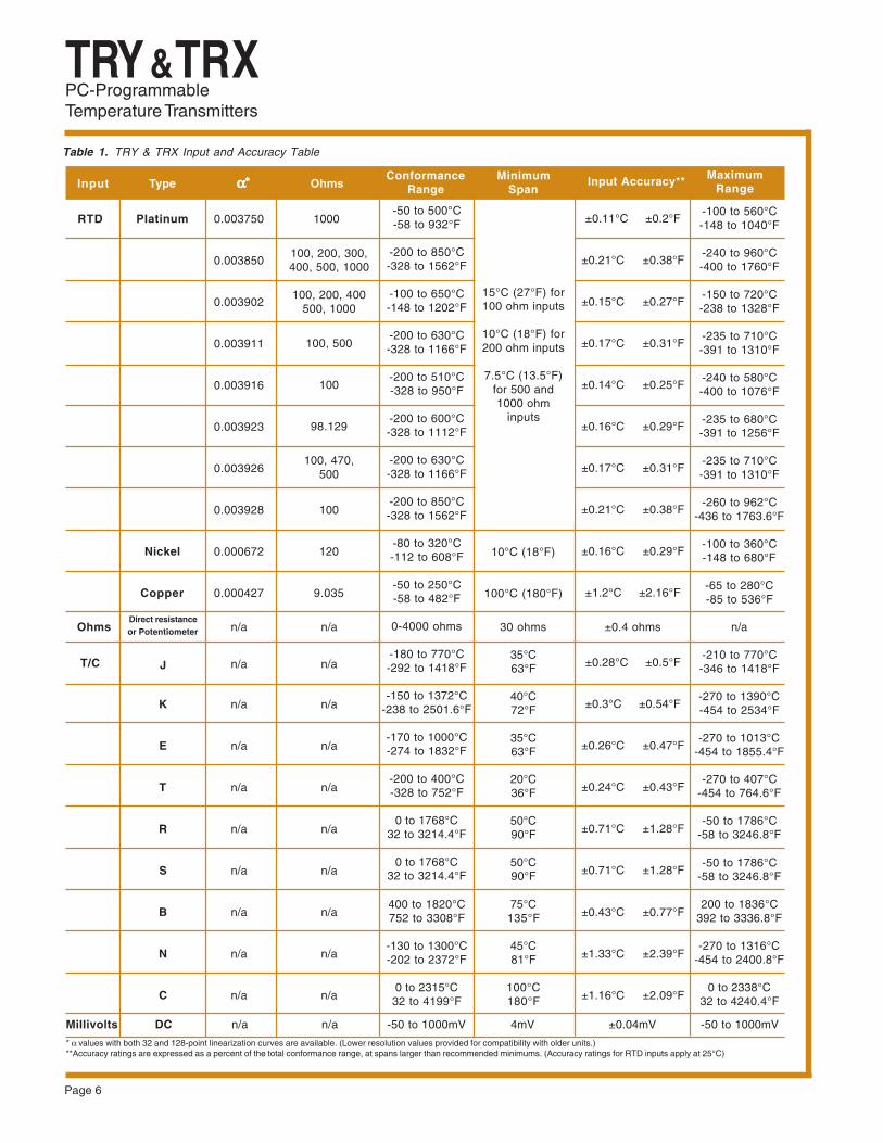
Table 1. TRY & TRX Input and Accuracy Table
0.003750
0.003850
0.003902
0.003911
0.003916
0.003923
0.003926
0.003928
0.000672
0.000427
n/a
n/a
n/a
n/a
n/a
n/a
n/a
n/a
n/a
n/a
100, 200, 300,400, 500, 1000
100, 200, 400500, 1000
100, 500
100
98.129
100, 470,500
100
120
9.035
n/a
n/a
n/a
n/a
n/a
n/a
n/a
n/a
n/a
n/a
-100 to 560°C-148 to 1040°F
-240 to 960°C-400 to 1760°F
-150 to 720°C-238 to 1328°F
-235 to 710°C-391 to 1310°F
-240 to 580°C-400 to 1076°F
-235 to 680°C-391 to 1256°F
-235 to 710°C-391 to 1310°F
-260 to 962°C-436 to 1763.6°F
-100 to 360°C-148 to 680°F
-65 to 280°C-85 to 536°F
n/a
-210 to 770°C-346 to 1418°F
-270 to 1390°C-454 to 2534°F
-270 to 1013°C-454 to 1855.4°F
-270 to 407°C-454 to 764.6°F
-50 to 1786°C-58 to 3246.8°F
-50 to 1786°C-58 to 3246.8°F
200 to 1836°C392 to 3336.8°F
-270 to 1316°C-454 to 2400.8°F
0 to 2338°C32 to 4240.4°F
RTD
T/C
Direct resistanceor Potentiometer
J
K
E
T
R
S
B
N
C
-50 to 500°C-58 to 932°F
-200 to 850°C-328 to 1562°F
-100 to 650°C-148 to 1202°F
-200 to 630°C-328 to 1166°F
-200 to 510°C-328 to 950°F
-200 to 600°C-328 to 1112°F
-200 to 630°C-328 to 1166°F
-200 to 850°C-328 to 1562°F
-80 to 320°C-112 to 608°F
-50 to 250°C-58 to 482°F
0-4000 ohms
-180 to 770°C-292 to 1418°F
-150 to 1372°C-238 to 2501.6°F
-170 to 1000°C-274 to 1832°F
-200 to 400°C-328 to 752°F
0 to 1768°C32 to 3214.4°F
0 to 1768°C32 to 3214.4°F
400 to 1820°C752 to 3308°F
-130 to 1300°C-202 to 2372°F
0 to 2315°C32 to 4199°F
Input Type ααααα∗∗∗∗∗ Ohms Conformance
Range Minimum
SpanInput Accuracy** Maximum
Range
15°C (27°F) for100 ohm inputs
10°C (18°F) for200 ohm inputs
7.5°C (13.5°F)for 500 and1000 ohm
inputs
10°C (18°F)
100°C (180°F)
30 ohms
35°C63°F
40°C72°F
35°C63°F
20°C36°F
50°C90°F
50°C90°F
75°C135°F
45°C81°F
100°C180°F
±0.11°C ±0.2°F
±0.21°C ±0.38°F
±0.15°C ±0.27°F
±0.17°C ±0.31°F
±0.14°C ±0.25°F
±0.16°C ±0.29°F
±0.17°C ±0.31°F
±0.21°C ±0.38°F
±0.16°C ±0.29°F
±1.2°C ±2.16°F
±0.4 ohms
±0.28°C ±0.5°F
±0.3°C ±0.54°F
±0.26°C ±0.47°F
±0.24°C ±0.43°F
±0.71°C ±1.28°F
±0.71°C ±1.28°F
±0.43°C ±0.77°F
±1.33°C ±2.39°F
±1.16°C ±2.09°F
* α values with both 32 and 128-point linearization curves are available. (Lower resolution values provided for compatibility with older units.)**Accuracy ratings are expressed as a percent of the total conformance range, at spans larger than recommended minimums. (Accuracy ratings for RTD inputs apply at 25°C)
Ohms
Millivolts DC n/a n/a -50 to 1000mV 4mV ±0.04mV -50 to 1000mV
Platinum
Nickel
Copper
1000
Page 7
TRY & TRXPC-Programmable
Temperature Transmitters
+ –
THERMOCOUPLEAND MILLIVOLT
INPUT
3-WIRE RTDOR DECADE
RESISTANCE BOX
4-WIRE RTDOR DECADE
RESISTANCE BOXPOTENTIOMETER
INPUT
23
4
1
23
4
1
23
4
1
23
4
1
23
4
1
2-WIRE RTDOR DECADE
RESISTANCE BOX
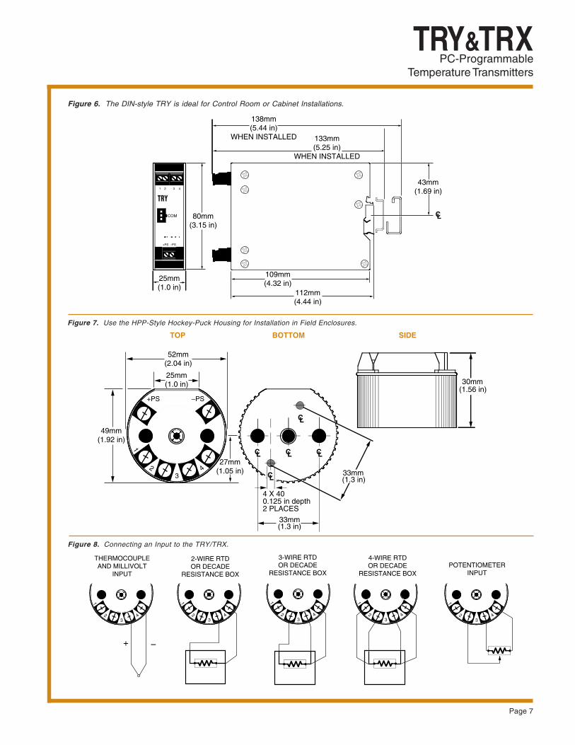
Figure 8. Connecting an Input to the TRY/TRX.
Figure 6. The DIN-style TRY is ideal for Control Room or Cabinet Installations.
Figure 7. Use the HPP-Style Hockey-Puck Housing for Installation in Field Enclosures.
30mm
–PS+PS
1
23
4
CL CLCL
CL
(1.56 in)
25mm(1.0 in)
52mm(2.04 in)
49mm(1.92 in)
27mm(1.05 in)
4 X 400.125 in depth2 PLACES
33mm(1.3 in)
LC33mm(1.3 in)
TOP BOTTOM SIDE
138mm(5.44 in)
WHEN INSTALLED 133mm(5.25 in)
WHEN INSTALLED
COM 80mm(3.15 in)
43mm(1.69 in)
112mm(4.44 in)
109mm(4.32 in)
25mm(1.0 in)
1 2 3 4
+PS –PS
CL
TRY

TRY & TRXPC-ProgrammableTemperature Transmitters
The Interface Solution Experts • www.miinet.comUnited States • [email protected]
Tel: (818) 894-7111 • FAX: (818) 891-2816 Australia • [email protected]
Tel: (02) 8536-7200 • FAX: (02) 9525-7296
Belgium • [email protected]: 03/448.10.18 • FAX: 03/440.17.97
The Netherlands • [email protected]: (0)344-617971 • FAX: (0)344-615920
China • [email protected]: 86-21-62481120 • FAX: 86-21-62490635
United Kingdom • [email protected]: 01293 514488 • FAX: 01293 536852
Figure 9. The TRY and TRX Feature Rugged, Fully Certified, Ready-to-Install Housing Styles.
Page 8
92mm(3.61 in)
9mm(0.35 in)
87mm(3.44 in)
ConduitEntry Port
89mm(3.5 in)
84mm(3.30 in)
CL
61mm(2.4 in)
2-in Pipe Bracket Mounting Holes (4)
61mm(2.4 in)
Process Connection1/2-in NPT (N and M models) or
G½ (BSP) (C models)
61mm(2.4 in)
10-32Mounting Holes (2)
51mm(2.0 in)
Safety Lock(LH2 only)
Metal Tag
BOTTOMINSIDE
2-INCH PIPE MOUNTING HARDWARE
30mm(1.2 in)
DIA. 72mm(DIA. 2.85 in)
InstrumentMounting Holes40mm (1.56 in)
InstrumentMountingHoles33mm(1.3 in)
I.D. 62mm x 19mm Deep(2.43 in x 0.76 in Deep)
Ground
M4.0 x 0.7 (4 places)
FRONT
SIDE
Printed in the U.S.A.