pcb mill - adam kumpf
TRANSCRIPT

6.115 Final Project
PCB Mill
Adam Kumpf
Project Advisor: Rahul Agrawal
Due: May 15, 2003

2
Overview of PCB Mill Document
1. Introduction:
1.1 What is a PCB Mill? 1.2 Design Concepts 1.3 Proposed Design
2. The Mechanical System 2.1 Mechanical Design 2.2 Mechanical Design Models 2.3 Tools/Supplies 2.4 Building the PCB Mill 3. The Electrical System 3.1 Circuit Block Diagram 3.2 Integrated Circuits Needed 3.3 Schematic/Layout 4. Implementing the Intel 805x/R31JP 4.1 Purpose 4.2 R31JP Flowchart 4.3 Explanation 5. Implementing the PIC16F877 5.1 Purpose 5.2 PIC16F877 Flowchart 5.3 Explanation 6. PCB Mill Software (C++) 6.1 Purpose 6.2 Design Concepts 6.3 .KMF Mill File Format 6.4 HPGL (.PLT) Plotter File Format 6.5 Features 6.6 Screenshots 7. Problems and Improvement Ideas Appendixes: Appendix A: R31JP Code Appendix B: PIC16F877 Code Appendix C: PIC16F877 Timing Diagram Appendix D: C++ Code

3
1. Introduction 1.1 What is a PCB Mill? A PCB Mill is a device that etches out a pattern on a copper clad board such that it makes a Printed Circuit Board (PCB). PCBs are used everywhere in the field of electrical engineering to connect electrical components to one another. Typically, after a board is designed, the layout files are sent to a manufacturer who then makes the board and ships it back to the customer. When prototyping, the delay and setup costs associated with sending a layout to a manufacturer can often mean days of down time. While this may not seem costly at first, it can prove to be a significant nuisance since most boards contain a wiring bug that was overlooked or misunderstood and must then be remade. The advantage of the PCB Mill is its ability to create a prototype in less than a couple hours and at a much reduced cost compared to outsourcing. The current price of a commercial PCB Milling device is around $3000 US which is a significant investment for most small labs or individuals wishing to quickly prototype. The solution: Make a PCB Mill from scratch using everyday parts. 1.2 Design Concepts The main concepts commonly used to make a milling device consist of a threaded travel mechanism, a combination X-axis and Y-axis, a precisely controlled motor (either a stepper motor or a DC motor with a position encoder), and a controller for the milling mechanism to correctly position it. For each axis - X,Y, and Z – a motor is connected to the threaded travel mechanism. As the motor turns the screw-like device, a guide on top of the thread moved back and forth in a straight 1-dimensional line. Combining the X-axis and the Y-axis, an XY-plane is created. This allows a platform to be positioned anywhere in a 2-dimensional plane. The Z axis, either mounted as port of the XY plane or separately above it, allows for a 3rd dimension.
With the help of a controller, the medium to be cut can be correctly placed in the XY-plane and the Z-axis, connected to a drilling device, can be raised or lowered to cut the desired path. With a well designed mill, accuracy of better than one thousandth of an inch can be achieved. 1.3 Proposed Design The design I am proposing uses 6 stepper motors to control the 3 axis of operation. (2 motors per axis) This is used instead of one motor per axis to minimize the likelihood of binding under a working load. Each stepper motor is connected to a push-pull driver chip which is controlled by a PIC16F877 microcontroller. The PIC chip displays the current position on an LCD and gets the desired position from the R31JP 805x microcontroller board. The operating system on the R31JP allows the user to download .kmf mill files and then command the system to carry out the milling operation. A PCB Milling program written in C++ is used to display, draw, and convert the standard HPGL plotter files to the .kmf milling file format.

4
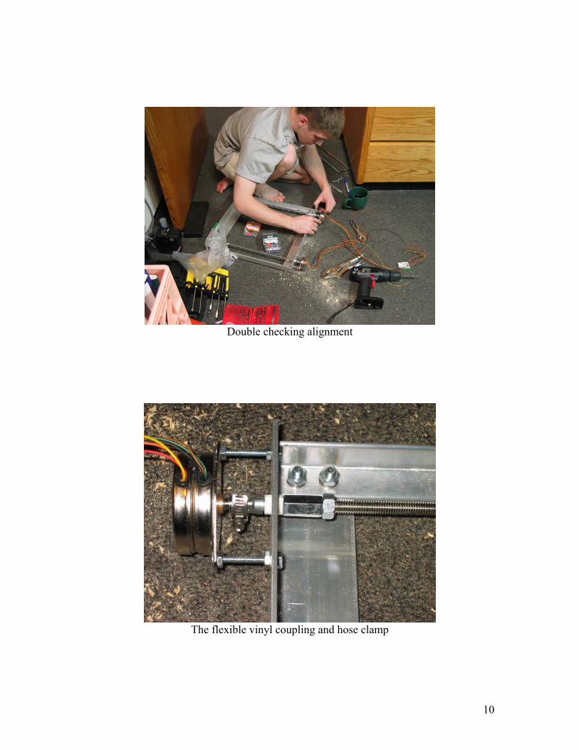
2. The Mechanical System 2.1 Mechanical Design The complete mechanical system was designed in a 3D solid working environment using Autodesk Inventor. Due to its light weight, strength, and cost, aluminum was chosen as the primary framing metal. This includes the main chassis of the mill which supports the X axis, the Y-axis, the 8” x 8” work area, and the Z-axis overhead support. Chassis connections were made with ¼” bolts where possible. The long threaded rod, or all-thread, is made of stainless steel to allow for moderately heavy loads on the work area. To couple the stepper motors to the threaded shaft, ¼” vinyl tubing and a hose clamp was used. This allows for some flexibility in the coupling and reduces non-torsional stresses which can needlessly overwork the motor. Uni-polar stepper motors were used, but could have easily been replaced with Bipolar stepper motors if desired. An AC motor is mounted on the Z-axis to perform the drilling operation. Ideally, a precision ¼” drill chuck would be mounted on the shaft of the AC drill motor for easy bit changing when necessary. 2.2 Mechanical Design Models
XY-Plane Design - Isometric View

5
Final Design - Front View
Final Design - Left View
6
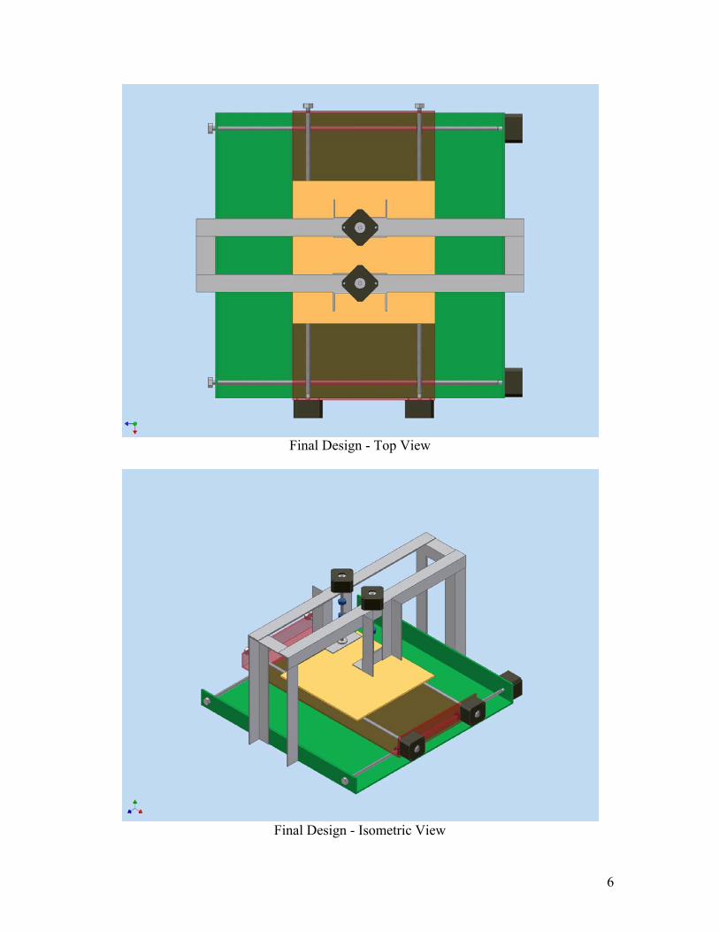
Final Design - Top View
Final Design - Isometric View

7
2.3 Tools/Supplies Supplies List: 6 x 48 steps/rev Stepper motors ¼” Vinyl tubing 6 x ¼” Hose clamps 8x32 Bolts/Nuts/Washers ¼” Bolts/Nuts/Lock-Washers .25”x8”x8” Aluminum Plate (for work area) 2”x2”x.125” Angle (4’ for side supports of chassis) 1”x1”x.125” Angle (10’ for other parts of chassis) 1”x.125” Rectangle (for AC motor U-bracket) 3 x 3’x5/16 Threaded Rod 14 x 5/16”x7/8” Hex Nut (for threaded rod mounting) Tools List: Hand Drill Drill Bits (1/16” – 3/8”) Hacksaw Hacksaw Blades (18 TPI for fast aluminum cutting) Dial Caliper (for precision measurements) Pliers Wrenches (1/4 – 7/16) Clamps to hold materials while working Bastard File for de-burring cuts Screwdrivers 8x32 Tap and Tap Wrench A Lot of Patience
2.4 Building the PCB Mill
Laying out the parts
8
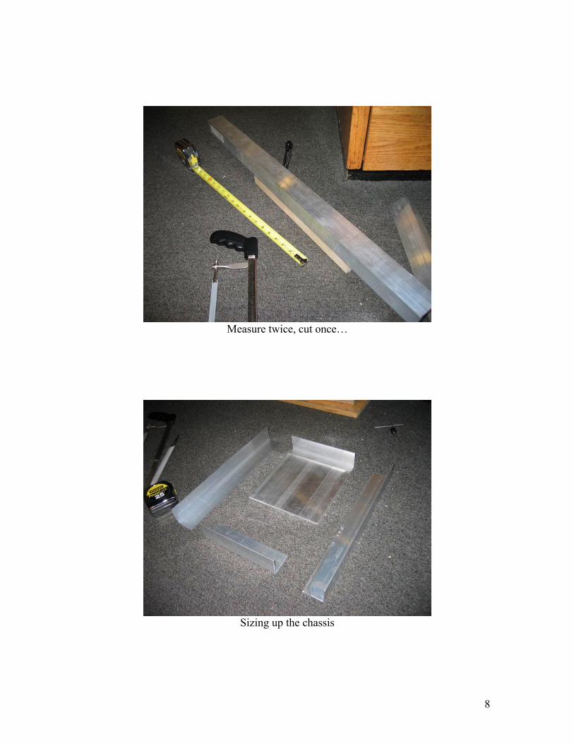
Measure twice, cut once…
Sizing up the chassis

9
Squaring things up
One motor mounted
10
Double checking alignment
The flexible vinyl coupling and hose clamp

11
Tapping holes in the hex guide nuts
It’s easy to be happy with a design before it’s tested…

12
Y-axis mounted onto X-Axis
Work plate mounted on top of Y axis

13
Bending both Z-axis supports at the same time to keep them identical
The AC motor mounted to the hex guide nuts for the Z-axis

14
Oiling the threaded rods to reduce friction
The complete Mechanical PCB Mill System

15
3. The Electrical System 3.1 Circuit Block Diagram
3.2 Integrated Circuits Used R31JP microcontroller board (Intel 805x) PIC16F877 microcontroller 6 x L293 Push Pull Driver D8255AC-2 Peripheral Interface Chip LCD Controller w/ LCD
R31JP / 805x (Decoding & Time
Sequencing)
D8255AC-2 Peripheral Interface
Chip
PIC16F877
L293
X-Axis Stepper A
L293
X-Axis Stepper B
L293
Y-Axis Stepper A
L293
Y-Axis Stepper B
L293
Z-Axis Stepper A
L293
Z-Axis Stepper B LCD
X=##### Y=##### Z=#####
+ -
17V
4 /
4 /
4 /
7
8 + 2
Memory Mapperd
RS-232 Serial PC

16
3.3 Schematic/Layout

17
4. Implementing the Intel 805x/R31JP 4.1 Purpose The purpose of using the Intel 805x/R31JP microcontroller board is to provide the user with an Operating System interface via the serial port and to allow the user to store the desired milling routine in external RAM. The device can then be asked by the user to carry out the milling process. To do this the R31JP communicates with the PIC16F877 through the D8255AC-2 Peripheral Interface Chip. Eight data lines and two control lines are used to send information. The Enable control lines is used to clock position data into the PIC16F877 and the MillReady line is driven high by the PIC microcontroller when it is ready for a new position.
18
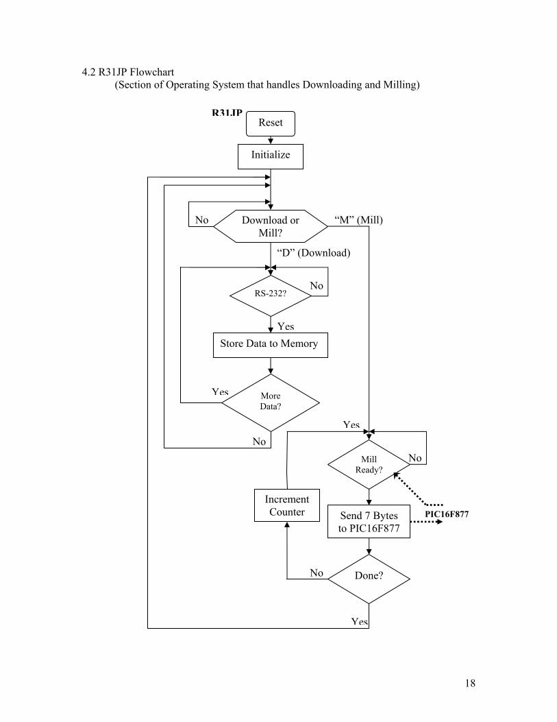
4.2 R31JP Flowchart (Section of Operating System that handles Downloading and Milling)
Reset
Initialize
RS-232?
Store Data to Memory
More Data?
Yes
No
R31JP
Mill Ready?
No
Yes
PIC16F877Send 7 Bytes to PIC16F877
Done?
Yes
No
Yes
Download or Mill?
No “M” (Mill)
“D” (Download)
No
Increment Counter

19
4.3 Explanation The R31JP program is based on the MinMon Operating System with a couple new commands that allow for downloading .KMF mill files and carrying out the actuall milling procedure. The R31JP is connected to a PC via a serial cable and communicates at a baud rate of 9600 bps to a communication window on the host computer. When the microcontroller is turned on, a welcome screen is printed and the device initializes local variables and the Peripheral Interface chip. If the user presses the “D” key, a prompt will be given instructing the user to send the .KMF file to the device. This can be done by treating the file as plain text and sending it over the RS-232 serial port. Since the .KMF mill file is very similar to the standard Intel Hex file, the operating system handles this routine nicely and sends a “.” handshake after each line is read. Each new mill position is stored in external RAM using only 5 bytes and can be retrieved at any time as long as power remains on to the device. After a .KMF mill file has been loaded into the external RAM, pressing the “M” key will cause the R31JP to begin the milling process. The microcontroller waits until the MillReady line goes high, signifying that the mill is awaiting it’s next command, and then sends 7 bytes of data to the PIC16F877 though the D8255AC-2 Peripheral Interface chip. The first byte is an instruction byte and currently does not affect the mill. The next six bytes correspond to the X, Y, and Z coordinates. For each axis, the most significant byte is sent first and is then folled by the least significant byte. See Appendix C: PIC16F877 Timing Diagram, for more information about how data is sent to the PIC16F877. Once all mill position data has been sent, a (0,0,0) position is sent to reset the mill to the origin and the user is returned to the main command dialog. 5. Implementing the PIC16F877 5.1 Purpose The purpose of the PIC16F877 is to abstract away the complexities of moving the stepper motors to a position linearly, controlling an LCD, and handling 12 stepper motor control lines. This allows the R31JP to simply send the desired position to the PIC16F877 and let the PIC do the rest of the calculations and movement control. Since the PIC chip runs at nearly 5 times the speed of the R31JP (5MHz machine clock of the PIC compared to the 1MHz machine clock of the R31JP) it also allows for more timing flexibility than the R31JP can handle alone.

20
5.2 PIC16F877 Flowchart
Reset
Initialize
Position Data?
No
Output Position to LCD
Yes
Done? Yes
Set MillReady Line High
Set MillReady Line Low
X,Y,Z Alone?
45° Angle?
Assume 22.5° Angle
No
No
No
Move Motors
Move Motors 45°
Move Motors 22.5°
PIC16F877
Yes
Yes

21
5.3 Explanation On startup, the mill assumes the position (0,0,0). All positions thereafter are relative to the startup position. Once all variables are initialized, the LCD is configured and the MillReady line is driven high to notify the R31JP that it is ready for a new position. Once a “goto” position has been received, the MillReady line is driven low and the LCD prints the desired destination. The mill first moves to the (X,Y) position and then changes the Z-axis position if needed. Since most PCB HPGL files try to make all angles between coordinates a multiple of 22.5°, there are 3 basic routines that the PIC16F877 can choose from to most accurately trace out a linear path. If the difference between the “goto” position and the current postion only differs along a single axis, the motors responsible for that axis are the only ones that are driven. If the absolute value of the difference of both X and Y are the same, a multiple of 45° is chosen appropriately. This involves turning both the X and Y stepper motors at the same rate, but possibly different directions.
The last angular choice is 22.5°. Since the stepper motors now driven at different rates, an approximation is made. That is, since the arctan(2/5) is 21.8° with an error of only 0.7°, one axis is stepped 5 times for every 2 times that the other axis is stepped. This however does not result in an incorrect final placement since the algorithm chosen continuously calculates the difference between the current position and the “goto” position and responds accordingly. Thus, if an angle of 35° is desired, the mill will trace out a 22.5° angle until a 45° angle exists between the current and “goto” position. The mill will then move at 45° until it has successfully come to rest at the exact desired position. Once the correct position has been achieved, the MillReady line is driven high to allow for the next postion to be sent from the R31JP. Since the R31JP always sends an origin vector (0,0,0) after the entire trace has been sent to the mill, the mill can be restarted and still retain the correct relative starting point. 6. PCB Mill Software (C++) 6.1 Purpose The purpose of the PCB Mill software is to provide a graphical environment that allows the user to easily create, modify, visualize, and convert HPGL plotter files. Once the desired layout has been achieved it can be saved as either as a .HPGL file for later use or as a .KMF file which can be sent to the mill over the serial cable. The program also allows for error checking such as negative coordinates or improperly using a drill layer to draw a PCB trace. 6.2 Design Concepts This piece of software was developed in Visual C++ due to the simplicity of implementing Graphical User Interfaces (GUIs). The graphical portion of the application was designed around a PaintBox object which uses the Canvas property to display an image. The core of the program focuses around a simple HPGL parser and interpreter. Since string manipulation is one of the drawbacks of C++, computation time while

22
parsing can be lengthy when processing long HPGL files. A 2x Zoom feature was also created to allow the user to more precisely inspect their design. 6.3 .KMF Mill File Format The Kumpf Mill File (.KMF) format is very similar to the Intel Hex file format to allow for easy downloading to the R31JP. The main difference is that all data lines are the same length. (5 bytes)
:05[Adr-MSB][Adr-LSB][R][I][X-MSB][X-LSB][Y-MSB][Y-LSB][Checksum]
Adr-MSB = Load Address Most Significant Byte Adr-LSB = Load Address Least Significant Byte R = Record Type (00 = data; 01 = end) I = Instruction (01 = move XY only;
02 = move XY, then move Z Up; Else = move XY, then move Z Down to ‘I’)
X-MSB = X position Most Significant Byte X-LSB = X position Least Significant Byte Y-MSB = Y position Most Significant Byte Y-LSB = Y position Least Significant Byte Checksum = 2’s compliment of sum of all preceding bytes (except “:”)
6.4 HPGL (.PLT) Plotter File Format The Hewlett-Packard Graphics Language (HPGL) is used to store 2-D drawings in an intuitive format that resembles picking-up, moving, and putting down a collection of pens. HPGL files are often saved with the extension .PLT to signify that they are used for plotting. The basic HPGL commands: SP# = Select Pen # PU = Pen Up PD = Pen Down PA[X],[Y] = Position Absolute X,Y
(move to a position relative to the origin) ; = command terminator The position of the plotter is specified in “plu”s. (plotter units) 1 Inch = 1016 plu’s. HPGL example: SP3;
PA2540,6096;PD; PA2286,5080; PA2032,4953; PA2032,4953;PU;

23
6.5 Features - 8”x8” work area identical to the Mill - Error checking for negative coordinates - Visual window to display trace and drilling of the mill - Ability to step through HPGL files - 1/8” snap grid and guidelines for easy alignment - Save both KMF and HPGL files - Ability to override milling depth and snap grid coordinates - Customize Threads per Inch and Steps per Revolution - Zoom by a factor of 2 and move in real-time - Print out traces and drills to scale
6.6 Screenshots
Visualization Control Panel

24
Mechanical Setup Dialog
Position Control Layout

25
.KMF File Output Window
Entire PCB Mill Application Window

26
7. Problems and Improvement Ideas The main problems I encountered with the PCB Mill were related to the mechanical system. It seems as though the threaded rods that I used had a slight bend to them. This causes the 8”x8” work area platform to move in a sinusoidal manner as the stepper motors turn. If the rods were straight, I believe the mill would work much better than it currently does.
A solution to the problem might be to add a few guide rails that keep each axis running straight and true. A simple felt-lined wooden shim may be all that’s needed to minimize the undesired vertical and horizontal movements.
Another problem was making a drill chuck for the AC motor that was relatively precise. If the milling/drill bit is not centered well, the resulting cut will be too large and the vibrations caused by it may drastically shorten the life of the machine.
Perhaps the best way to solve this problem would be to make sure the AC motor shaft used has the same diameter as the drill chuck such that they can be easily coupled. It is also important to balance the drill chuck to minimize vibrations.
One final improvement would be to take out one of the microcontrollers to simplify the design. Since the R31JP controller board contains many components and is fairly large in size, I think it would be good to try doing everything on the PIC16F877. The system could then be practical enough that people from all over could reproduce this project fairly easily.

27
Appendixes: Appendix A: R31JP Code ; ************************************************* ; * * ; * MINMON - The Minimal 8051 Monitor Program * ; * * ; * Portions of this program are courtesy of * ; * Rigel Corporation, of Gainesville, Florida * ; * * ; * Modified for 6.115 * ; * Massachusetts Institute of Technology * ; * January, 2001 Steven B. Leeb * ; * May 2003, Adam A. Kumpf * ; * * ; ************************************************* stack equ 2fh ; bottom of stack ; - stack starts at 30h - errorf equ 0 ; bit 0 is error status TXdata equ 90 ; Data to be transmitted to the PIC InstByte equ 91 ; Instruction byte LastZcoor equ 92 ; Hold last value of Z Position. ;================================================================= ; 8032 hardware vectors ;================================================================= org 00h ; power up and reset vector ljmp start org 03h ; interrupt 0 vector ljmp start org 0bh ; timer 0 interrupt vector ljmp start org 13h ; interrupt 1 vector ljmp start org 1bh ; timer 1 interrupt vector ljmp start org 23h ; serial port interrupt vector ljmp start org 2bh ; 8052 extra interrupt vector ljmp start ;================================================================= ; begin main program ;================================================================= org 100h ; 100h ;;; CHANGE FOR ROM!!!!!! start: clr ea ; disable interrupts lcall init ; initialize hardware lcall print ; print welcome message db 0ah, 0dh, 0ah, 0dh, 0ah, 0dh db " | | ", 0ah, 0dh db " |z| y ", 0ah, 0dh db " +------------------+ +--\\|/--------+ ", 0ah, 0dh db " | 6.115 | / V /+ ", 0ah, 0dh db " | PCB Mill | / .__/ // ", 0ah, 0dh db " | Adam Kumpf | +_____________+/ ", 0ah, 0dh db " +------------------+ +=============+ ->x ", 0ah, 0dh
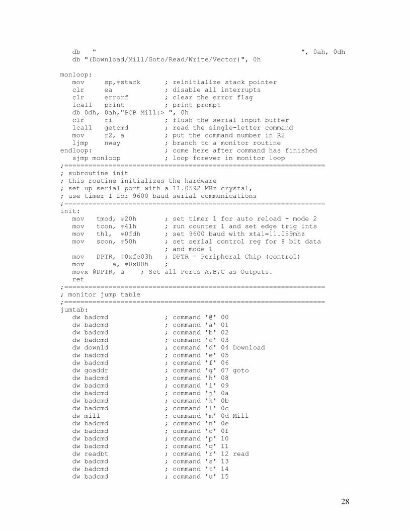
28
db " ", 0ah, 0dh db "(Download/Mill/Goto/Read/Write/Vector)", 0h monloop: mov sp,#stack ; reinitialize stack pointer clr ea ; disable all interrupts clr errorf ; clear the error flag lcall print ; print prompt db 0dh, 0ah,"PCB Mill:> ", 0h clr ri ; flush the serial input buffer lcall getcmd ; read the single-letter command mov r2, a ; put the command number in R2 ljmp nway ; branch to a monitor routine endloop: ; come here after command has finished sjmp monloop ; loop forever in monitor loop ;================================================================= ; subroutine init ; this routine initializes the hardware ; set up serial port with a 11.0592 MHz crystal, ; use timer 1 for 9600 baud serial communications ;================================================================= init: mov tmod, #20h ; set timer 1 for auto reload - mode 2 mov tcon, #41h ; run counter 1 and set edge trig ints mov th1, #0fdh ; set 9600 baud with xtal=11.059mhz mov scon, #50h ; set serial control reg for 8 bit data ; and mode 1 mov DPTR, #0xfe03h ; DPTR = Peripheral Chip (control) mov a, #0x80h ; movx @DPTR, a ; Set all Ports A,B,C as Outputs. ret ;================================================================= ; monitor jump table ;================================================================= jumtab: dw badcmd ; command '@' 00 dw badcmd ; command 'a' 01 dw badcmd ; command 'b' 02 dw badcmd ; command 'c' 03 dw downld ; command 'd' 04 Download dw badcmd ; command 'e' 05 dw badcmd ; command 'f' 06 dw goaddr ; command 'g' 07 goto dw badcmd ; command 'h' 08 dw badcmd ; command 'i' 09 dw badcmd ; command 'j' 0a dw badcmd ; command 'k' 0b dw badcmd ; command 'l' 0c dw mill ; command 'm' 0d Mill dw badcmd ; command 'n' 0e dw badcmd ; command 'o' 0f dw badcmd ; command 'p' 10 dw badcmd ; command 'q' 11 dw readbt ; command 'r' 12 read dw badcmd ; command 's' 13 dw badcmd ; command 't' 14 dw badcmd ; command 'u' 15

29
dw vectwr ; command 'v' 16 vector wite dw writebt ; command 'w' 17 write dw badcmd ; command 'x' 18 dw badcmd ; command 'y' 19 dw badcmd ; command 'z' 1a ;***************************************************************** ; monitor command routines ;***************************************************************** ;=============================================================== ; command goaddr 'g' ; this routine branches to the 4 hex digit address which follows ;=============================================================== goaddr: lcall getbyt ; get address high byte mov r7, a ; save in R7 lcall prthex lcall getbyt ; get address low byte push acc ; push lsb of jump address lcall prthex lcall crlf mov a, r7 ; recall address high byte push acc ; push msb of jump address ret ; do jump by doing a ret ;=============================================================== ; command downld 'd' ; this command reads in an Intel hex file from the serial port ; and stores it in external memory. ;=============================================================== downld: lcall print ; print "Ready to Receive .kmf File" db 0ah, 0dh, "Ready to Receive .kmf File", 0h lcall crlf mov a, #'>' ; acknowledge by a '>' lcall sndchr dl: lcall getchr ; read in ':' cjne a, #':', dl lcall getbytx ; get hex length byte jz enddl ; if length=0 then return mov r0, a ; save length in r0 lcall getbytx ; get msb of address setb acc.7 ; make sure it is in RAM mov dph, a ; save in dph lcall getbytx ; get lsb of address mov dpl, a ; save in dpl lcall getbytx ; read in special purpose byte (ignore) dloop: lcall getbytx ; read in data byte movx @dptr, a ; save in ext mem inc dptr ; bump mem pointer djnz r0, dloop ; repeat for all data bytes in record lcall getbytx ; read in checksum, but ignore mov a, #'.' lcall sndchr ; handshake '.' sjmp dl ; read in next record enddl:

30
lcall getbytx ; read in remainder of the lcall getbytx ; termination record lcall getbytx lcall getbytx mov a, #'.' lcall sndchr ; handshake '.' mov a, #0x00h ; store "zero" byte to end download. movx @dptr, a ; save in ext mem ljmp endloop ; return getbytx: lcall getbyt jb errorf, gb_err ret gb_err: ljmp badpar ;***************************************************************** ; monitor support routines ;***************************************************************** badcmd: lcall print db 0dh, 0ah," bad command ", 0h ljmp endloop badpar: lcall print db 0dh, 0ah," bad parameter ", 0h ljmp endloop ;=============================================================== ; subroutine getbyt ; this routine reads in an 2 digit ascii hex number from the ; serial port. the result is returned in the acc. ;=============================================================== getbyt: lcall getchr ; get msb ascii chr lcall ascbin ; conv it to binary swap a ; move to most sig half of acc mov b, a ; save in b lcall getchr ; get lsb ascii chr lcall ascbin ; conv it to binary orl a, b ; combine two halves ret ;=============================================================== ; subroutine getcmd ; this routine gets the command line. currently only a ; single-letter command is read - all command line parameters ; must be parsed by the individual routines. ; ;=============================================================== getcmd: lcall getchr ; get the single-letter command clr acc.5 ; make upper case lcall sndchr ; echo command clr C ; clear the carry flag subb a, #'@' ; convert to command number jnc cmdok1 ; letter command must be above '@' lcall badpar cmdok1:

31
push acc ; save command number subb a, #1Bh ; command number must be 1Ah or less jc cmdok2 lcall badpar ; no need to pop acc since badpar ; initializes the system cmdok2: pop acc ; recall command number ret ;=============================================================== ; subroutine nway ; this routine branches (jumps) to the appropriate monitor ; routine. the routine number is in r2 ;================================================================ nway: mov dptr, #jumtab ;point dptr at beginning of jump table mov a, r2 ;load acc with monitor routine number rl a ;multiply by two. inc a ;load first vector onto stack movc a, @a+dptr ; " " push acc ; " " mov a, r2 ;load acc with monitor routine number rl a ;multiply by two movc a, @a+dptr ;load second vector onto stack push acc ; " " ret ;jump to start of monitor routine ;***************************************************************** ; general purpose routines ;***************************************************************** ;=============================================================== ; subroutine sndchr ; this routine takes the chr in the acc and sends it out the ; serial port. ;=============================================================== sndchr: clr scon.1 ; clear the tx buffer full flag. mov sbuf,a ; put chr in sbuf txloop: jnb scon.1, txloop ; wait till chr is sent ret ;=============================================================== ; subroutine getchr ; this routine reads in a chr from the serial port and saves it ; in the accumulator. ;=============================================================== getchr: jnb ri, getchr ; wait till character received mov a, sbuf ; get character anl a, #7fh ; mask off 8th bit clr ri ; clear serial status bit ret ;=============================================================== ; subroutine print ; print takes the string immediately following the call and ; sends it out the serial port. the string must be terminated ; with a null. this routine will ret to the instruction

32
; immediately following the string. ;=============================================================== print: pop dph ; put return address in dptr pop dpl prtstr: clr a ; set offset = 0 movc a, @a+dptr ; get chr from code memory cjne a, #0h, mchrok ; if termination chr, then return sjmp prtdone mchrok: lcall sndchr ; send character inc dptr ; point at next character sjmp prtstr ; loop till end of string prtdone: mov a, #1h ; point to instruction after string jmp @a+dptr ; return ;=============================================================== ; subroutine crlf ; crlf sends a carriage return line feed out the serial port ;=============================================================== crlf: mov a, #0ah ; print lf lcall sndchr cret: mov a, #0dh ; print cr lcall sndchr ret ;=============================================================== ; subroutine prthex ; this routine takes the contents of the acc and prints it out ; as a 2 digit ascii hex number. ;=============================================================== prthex: push acc lcall binasc ; convert acc to ascii lcall sndchr ; print first ascii hex digit mov a, r2 ; get second ascii hex digit lcall sndchr ; print it pop acc ret ;=============================================================== ; subroutine binasc ; binasc takes the contents of the accumulator and converts it ; into two ascii hex numbers. the result is returned in the ; accumulator and r2. ;=============================================================== binasc: mov r2, a ; save in r2 anl a, #0fh ; convert least sig digit. add a, #0f6h ; adjust it jnc noadj1 ; if a-f then readjust add a, #07h noadj1: add a, #3ah ; make ascii xch a, r2 ; put result in reg 2 swap a ; convert most sig digit

33
anl a, #0fh ; look at least sig half of acc add a, #0f6h ; adjust it jnc noadj2 ; if a-f then re-adjust add a, #07h noadj2: add a, #3ah ; make ascii ret ;=============================================================== ; subroutine ascbin ; this routine takes the ascii character passed to it in the ; acc and converts it to a 4 bit binary number which is returned ; in the acc. ;=============================================================== ascbin: clr errorf add a, #0d0h ; if chr > 30 then error jnc notnum clr c ; check if chr is 0-9 add a, #0f6h ; adjust it jc hextry ; jmp if chr not 0-9 add a, #0ah ; if it is then adjust it ret hextry: clr acc.5 ; convert to upper clr c ; check if chr is a-f add a, #0f9h ; adjust it jnc notnum ; if not a-f then error clr c ; see if char is 46 or less. add a, #0fah ; adjust acc jc notnum ; if carry then not hex anl a, #0fh ; clear unused bits ret notnum: setb errorf ; if not a valid digit ljmp endloop ;=============================================================== ; mon_return is not a subroutine. ; it simply jumps to address 0 which resets the system and ; invokes the monitor program. ; A jump or a call to mon_return has the same effect since ; the monitor initializes the stack. ;=============================================================== mon_return: ljmp 0 ;=============================================================== ; command readbt 'R' ; this routine reads the 4 hex digit address which follows ;=============================================================== readbt: lcall getbyt ; get address high byte mov dph, a ; put in DPH lcall prthex
34
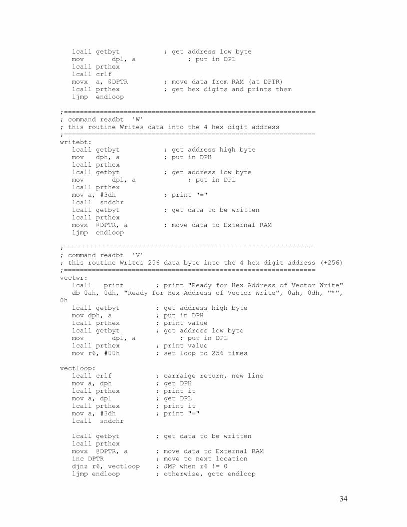
lcall getbyt ; get address low byte mov dpl, a ; put in DPL lcall prthex lcall crlf movx a, @DPTR ; move data from RAM (at DPTR) lcall prthex ; get hex digits and prints them ljmp endloop ;=============================================================== ; command readbt 'W' ; this routine Writes data into the 4 hex digit address ;=============================================================== writebt: lcall getbyt ; get address high byte mov dph, a ; put in DPH lcall prthex lcall getbyt ; get address low byte mov dpl, a ; put in DPL lcall prthex mov a, #3dh ; print "=" lcall sndchr lcall getbyt ; get data to be written lcall prthex movx @DPTR, a ; move data to External RAM ljmp endloop ;=============================================================== ; command readbt 'V' ; this routine Writes 256 data byte into the 4 hex digit address (+256) ;=============================================================== vectwr: lcall print ; print "Ready for Hex Address of Vector Write" db 0ah, 0dh, "Ready for Hex Address of Vector Write", 0ah, 0dh, "*", 0h lcall getbyt ; get address high byte mov dph, a ; put in DPH lcall prthex ; print value lcall getbyt ; get address low byte mov dpl, a ; put in DPL lcall prthex ; print value mov r6, #00h ; set loop to 256 times vectloop: lcall crlf ; carraige return, new line mov a, dph ; get DPH lcall prthex ; print it mov a, dpl ; get DPL lcall prthex ; print it mov a, #3dh ; print "=" lcall sndchr lcall getbyt ; get data to be written lcall prthex movx @DPTR, a ; move data to External RAM inc DPTR ; move to next location djnz r6, vectloop ; JMP when r6 != 0 ljmp endloop ; otherwise, goto endloop

35
;=============================================================== ; command readbt 'M' ; this routine Runs the Mill ;=============================================================== mill: lcall print ; print " Milling" db 0ah, 0dh, " Milling:", 0h lcall mill_init ; Setup Mill mill_loop jnb P3.5, mill_loop ; Wait for Mill Ready line to go high movx a, @DPTR mov InstByte, a jnz keep_milling ; is value zero? lcall print ; print " Milling Complete - Returning to Origin" db 0ah, 0dh, " Milling Complete - Returning to Origin", 0ah, 0dh, 0h ljmp lastmill keep_milling: lcall mill_send ; send Instruction Byte (currently not used.) inc DPTR ; Get and Send XgotoH movx a, @DPTR mov TXdata, a lcall mill_send inc DPTR ; Get and Send XgotoL movx a, @DPTR mov TXdata, a lcall mill_send inc DPTR ; Get and Send YgotoH movx a, @DPTR mov TXdata, a lcall mill_send inc DPTR ; Get and Send YgotoL movx a, @DPTR mov TXdata, a lcall mill_send mov TXdata, #0x00h ; write ZgotoH (zero for now) lcall mill_send mov a, InstByte ; move Instruction Byte to Accum cjne a, #0x01h, mill_newZ ; Simply change x&y position (no Z movement) mov a, LastZcoor ; write ZgotoL (LastZcoor) mov TXdata, a lcall mill_send ljmp milling_shake ; send handshake (skip mill_newZ) mill_newZ: mov a, InstByte ; ZgotoL (Instruction) cjne a, #0x02h, mill_Zdown ; check to see if mill is going down/up mov LastZcoor, #0x00h ; Mill going up - set position to Zero. mov TXdata, #0x00h

36
lcall mill_send ; write ZgotoL (Zero) ljmp milling_shake ; send handshake (skip mill_Zdown) mill_Zdown: mov a, InstByte ; ZgotoL (Instruction) mov LastZcoor, a ; save Z coor for next time through mov TXdata, a ; write ZgotoL (Instruction) lcall mill_send milling_shake: mov a, #'*' lcall sndchr ; handshake '.' inc DPTR ljmp mill_loop ; repeat until finished lastmill: lcall mill_send ; send Instruction Byte (currently not used.) mov TXdata, #0x00h lcall mill_send ; Send XgotoH = 0 (origin) lcall mill_send ; Send XgotoL = 0 (origin) lcall mill_send ; Send YgotoH = 0 (origin) lcall mill_send ; Send YgotoL = 0 (origin) lcall mill_send ; Send ZgotoH = 0 (origin) lcall mill_send ; Send ZgotoL = 0 (origin) lastmill_wait: jnb P3.5, lastmill_wait ; Wait for Mill Ready line to go high lcall print ; print "Mill Ready... (Download/Mill/Goto/Read/Write/Vector)" db "Mill Ready...",0ah, 0dh, "(Download/Mill/Goto/Read/Write/Vector)", 0h ljmp endloop ; return to main prompt. mill_init: mov DPTR, #0x8000h ; Set DPTR to first location in RAM ret mill_send: push dph push dpl mov DPTR, #0xfe01h mov a, TXdata movx @DPTR, a ; Move data to PORTB nop nop mov DPTR, #0xfe02h mov a, #0x01h movx @DPTR, a ; set enable high nop nop

37
mov a, #0x00h movx @DPTR, a ; set enable low pop dpl pop dph ret Appendix B: PIC16F877 Code ;################################################################### ;# # ;# This Program takes in 3 16-bit values and sends # ;# the correct output to stepper motors (x, y, z) # ;# which can then be used to control a Milling Machine.# ;# # ;# # ;################################################################### ;; Definitions: format "[7,6,5,4,3,2,1,0]" ;; PORTB(output) = [DB7,DB6,DB5,DB4,E,R/W,RS,x] (LCD) ;; PORTA(output) = [x,x,x,x,Zd,Zc,Zb,Za] ;; PORTD(output) = [Yd,Yc,Yb,Ya,Xd,Xc,Xb,Xa] ;; PORTC(Input) = [d7,d6,d5,d4,d3,d2,d1,d0] (From R31JP) ;; PORTE(In/Out) = [x,x,x,x,x,x,MillReady(o),Enable(i)] list p=16f877 include <p16F877.inc> ;######################################### ;# Variable Declarations (0x20 - 0x7f) # ;######################################### d0 equ 0x20 ; General Temp Varaible d1 equ 0X21 ; General Temp Varaible d2 equ 0x22 ; General Temp Varaible d3 equ 0x23 ; General Temp Varaible d4 equ 0x24 ; General Temp Varaible XcoorL equ 0x25 ; Current X Coordinate (LSB) XcoorH equ 0x26 ; Current X Coordinate (MSB) YcoorL equ 0x27 ; Current Y Coordinate (LSB) YcoorH equ 0x28 ; Current Y Coordinate (MSB) ZcoorL equ 0x29 ; Current Z Coordinate (LSB) ZcoorH equ 0x2a ; Current Z Coordinate (MSB) XgotoL equ 0x2b ; goto X Coordinate (LSB) XgotoH equ 0x2c ; goto X Coordinate (MSB) YgotoL equ 0x2d ; goto Y Coordinate (LSB) YgotoH equ 0x2e ; goto Y Coordinate (MSB) ZgotoL equ 0x2f ; goto Z Coordinate (LSB) ZgotoH equ 0x30 ; goto Z Coordinate (MSB) Xcurstep equ 0x31 ; X stepper motor position Ycurstep equ 0x32 ; Y stepper motor position Zcurstep equ 0x33 ; Z stepper motor position NumH equ 0x34 ; variables for BCD conversion NumL equ 0x35 ; variables for BCD conversion TenK equ 0x36 ; Ten Thousands place
38
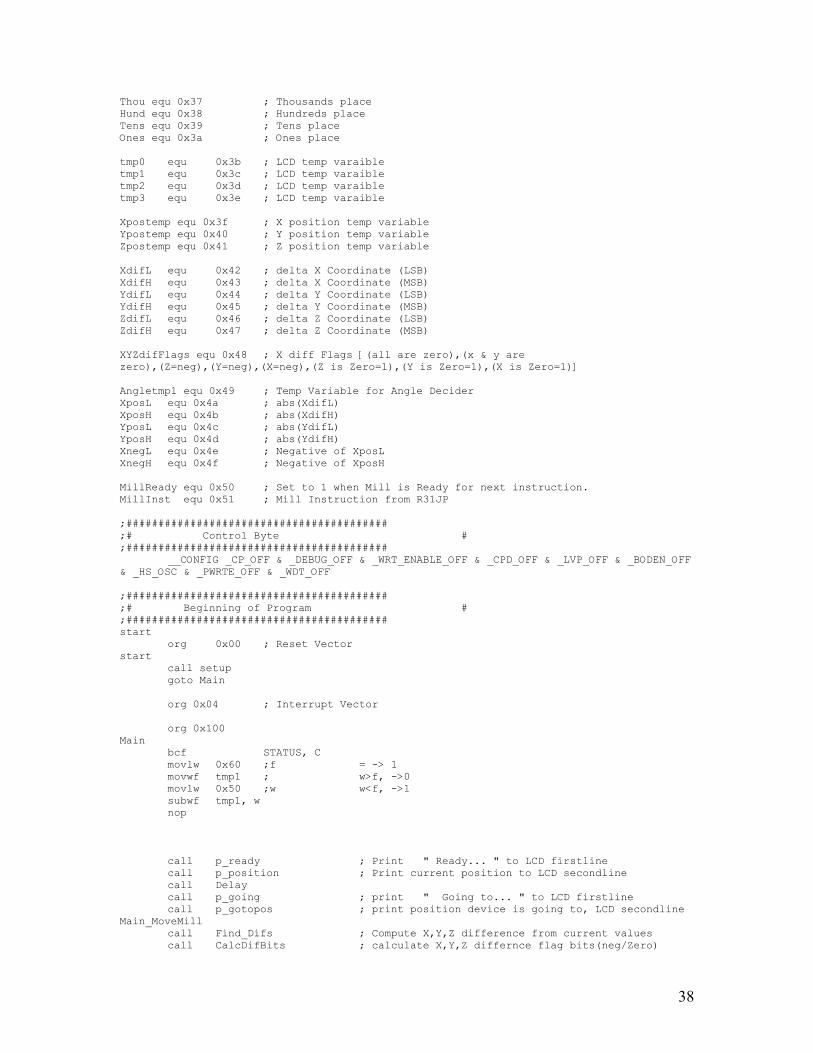
Thou equ 0x37 ; Thousands place Hund equ 0x38 ; Hundreds place Tens equ 0x39 ; Tens place Ones equ 0x3a ; Ones place tmp0 equ 0x3b ; LCD temp varaible tmp1 equ 0x3c ; LCD temp varaible tmp2 equ 0x3d ; LCD temp varaible tmp3 equ 0x3e ; LCD temp varaible Xpostemp equ 0x3f ; X position temp variable Ypostemp equ 0x40 ; Y position temp variable Zpostemp equ 0x41 ; Z position temp variable XdifL equ 0x42 ; delta X Coordinate (LSB) XdifH equ 0x43 ; delta X Coordinate (MSB) YdifL equ 0x44 ; delta Y Coordinate (LSB) YdifH equ 0x45 ; delta Y Coordinate (MSB) ZdifL equ 0x46 ; delta Z Coordinate (LSB) ZdifH equ 0x47 ; delta Z Coordinate (MSB) XYZdifFlags equ 0x48 ; X diff Flags [(all are zero),(x & y are zero),(Z=neg),(Y=neg),(X=neg),(Z is Zero=1),(Y is Zero=1),(X is Zero=1)] Angletmp1 equ 0x49 ; Temp Variable for Angle Decider XposL equ 0x4a ; abs(XdifL) XposH equ 0x4b ; abs(XdifH) YposL equ 0x4c ; abs(YdifL) YposH equ 0x4d ; abs(YdifH) XnegL equ 0x4e ; Negative of XposL XnegH equ 0x4f ; Negative of XposH MillReady equ 0x50 ; Set to 1 when Mill is Ready for next instruction. MillInst equ 0x51 ; Mill Instruction from R31JP ;######################################### ;# Control Byte # ;######################################### __CONFIG _CP_OFF & _DEBUG_OFF & _WRT_ENABLE_OFF & _CPD_OFF & _LVP_OFF & _BODEN_OFF & _HS_OSC & _PWRTE_OFF & _WDT_OFF ;######################################### ;# Beginning of Program # ;######################################### start org 0x00 ; Reset Vector start call setup goto Main org 0x04 ; Interrupt Vector org 0x100 Main bcf STATUS, C movlw 0x60 ;f = -> 1 movwf tmp1 ; w>f, ->0 movlw 0x50 ;w w<f, ->1 subwf tmp1, w nop call p_ready ; Print " Ready... " to LCD firstline call p_position ; Print current position to LCD secondline call Delay call p_going ; print " Going to... " to LCD firstline call p_gotopos ; print position device is going to, LCD secondline Main_MoveMill call Find_Difs ; Compute X,Y,Z difference from current values call CalcDifBits ; calculate X,Y,Z differnce flag bits(neg/Zero)

39
call MoveMotors call step_delay ; stepper motor delay btfss MillReady, 0 ; Check if Mill is done working. goto Main_MoveMill Main_newPos1 bsf PORTE, 1 ; Ready for instruction... btfss PORTE, 0 ; Wait for Instruction from R31JP goto Main_newPos1 Main_newPos2 movf PORTC, w ; get Mill Instruction movwf MillInst bcf MillReady, 0 bcf PORTE, 1 ; Clear MillReady bit for next time. Main_newPos3 btfsc PORTE, 0 ; wait for Enable to clear. goto Main_newPos3 Main_newPos4 btfss PORTE, 0 ; wait for Enable to go High. goto Main_newPos4 Main_newPos5 movf PORTC, w ; get Mill XgotoH movwf XgotoH Main_newPos6 btfsc PORTE, 0 ; wait for Enable to clear. goto Main_newPos6 Main_newPos7 btfss PORTE, 0 ; wait for Enable to go High. goto Main_newPos7 Main_newPos8 movf PORTC, w ; get Mill XgotoL movwf XgotoL Main_newPos9 btfsc PORTE, 0 ; wait for Enable to clear. goto Main_newPos9 Main_newPos10 btfss PORTE, 0 ; wait for Enable to go High. goto Main_newPos10 Main_newPos11 movf PORTC, w ; get Mill YgotoH movwf YgotoH Main_newPos12 btfsc PORTE, 0 ; wait for Enable to clear. goto Main_newPos12 Main_newPos13 btfss PORTE, 0 ; wait for Enable to go High. goto Main_newPos13 Main_newPos14 movf PORTC, w ; get Mill YgotoL movwf YgotoL Main_newPos15 btfsc PORTE, 0 ; wait for Enable to clear. goto Main_newPos15 Main_newPos16 btfss PORTE, 0 ; wait for Enable to go High. goto Main_newPos16 Main_newPos17 movf PORTC, w ; get Mill ZgotoH movwf ZgotoH Main_newPos18 btfsc PORTE, 0 ; wait for Enable to clear. goto Main_newPos18 Main_newPos19 btfss PORTE, 0 ; wait for Enable to go High. goto Main_newPos19 Main_newPos20

40
movf PORTC, w ; get Mill ZgotoL movwf ZgotoL Main_newPos21 btfsc PORTE, 0 ; wait for Enable to clear. goto Main_newPos21 call p_going ; print " Going to... " to LCD firstline call p_gotopos ; print position device is going to, LCD secondline goto Main_MoveMill ; Everything's ok.. Move the Mill. setup bsf STATUS, RP0 ; Control Page movlw b'00000000' movwf TRISB ; Set PORTB = Output to LCD display movwf TRISD ; Set PORTD = Output of x & y stepper motors movwf TRISA ; Set PORTA = Output of z stepper movlw b'11111111' movwf TRISC ; Set PORTE = Input data from R31JP movlw b'00000101' movwf TRISE ; Set PORTE = Input E line and Output MillReady movlw b'00000111' movwf ADCON1 ; allow PORTE to be used an digital inputs. bcf STATUS, RP0 ; Clear Control Page movlw b'01110111' movwf PORTD bsf PORTE, 1 bcf PORTE, 1 ; not ready for instruction yet. call initialize ; Setup LCD movlw 0x00 movwf XcoorL ; startup with pos = (0,0,0) movwf XcoorH ; startup with pos = (0,0,0) movlw 0x00 movwf YcoorL ; startup with pos = (0,0,0) movwf YcoorH ; startup with pos = (0,0,0) movlw 0x00 movwf ZcoorL ; startup with pos = (0,0,0) movwf ZcoorH ; startup with pos = (0,0,0) movlw 0x00 movwf XgotoL ; startup with goto pos = (0,0,0) movwf XgotoH ; startup with goto pos = (0,0,0) movwf YgotoL ; startup with goto pos = (0,0,0) movwf YgotoH ; startup with goto pos = (0,0,0) movwf ZgotoL ; startup with goto pos = (0,0,0) movwf ZgotoH ; startup with goto pos = (0,0,0) movlw b'01110111' movwf Xcurstep ; startup with current stepper pos = 0x77 movwf Ycurstep ; startup with current stepper pos = 0x77 movwf Zcurstep ; startup with current stepper pos = 0x77 clrf XdifL ; Set difference values to 0 at startup clrf XdifH ; Set difference values to 0 at startup clrf YdifL ; Set difference values to 0 at startup clrf YdifH ; Set difference values to 0 at startup clrf ZdifL ; Set difference values to 0 at startup clrf ZdifH ; Set difference values to 0 at startup clrf MillReady ; start mill off not ready yet. return ;######################################### ;# Inc/Dec Move Loop Routines # ;######################################### MoveMotors btfsc XYZdifFlags, 7 ; Are all differences zero? goto motors_all_zero btfsc XYZdifFlags, 6 ; Are just X and Y zero? (Z may be non-zero here) goto motors_just_z ; Must be X or Y or both here... (Z not allowed)

41
btfsc XYZdifFlags, 0 ; Is X zero? goto motors_y_alone ; Must be Y difference Alone btfsc XYZdifFlags, 1 ; Is Y zero? (if so, then X is difference alone) goto motors_x_alone ; Must be Both X And Y movement!
; (no X & Y & Z allowed) movf XdifH, w movwf XposH movf XdifL, w movwf XposL movf YdifH, w movwf YposH movf YdifL, w movwf YposL ; Calculate Absolute value of Xdif and Ydif btfss XdifH, 7 goto Xnotneg ; 2's Compliment to get Positive value! bcf STATUS, C ; clear the carry flag comf XdifL,w ; calculate the 1's complement of the LSB for subtraction movwf XposL comf XdifH,w ; calculate the 1's complement of the MSB for subtraction movwf XposH movf XposL,w addlw 0x01 ; add 1 to the LSB 1st complement to get the 2's complement movwf XposL btfsc STATUS,C ; test the carry flag, if a carry occurred incf XposH,f ; add 1 to the MSB register if Carry occured Xnotneg btfss YdifH, 7 goto Ynotneg ; 2's Compliment to get Positive value! bcf STATUS, C ; clear the carry flag comf YdifL,w ; calculate the 1's complement of the LSB for subtraction movwf YposL comf YdifH,w ; calculate the 1's complement of the MSB for subtraction movwf YposH movf YposL,w addlw 0x01 ; add 1 to the LSB 1st complement to get the 2's complement movwf YposL btfsc STATUS,C ; test the carry flag, if a carry occurred incf YposH,f ; add 1 to the MSB register if Carry occured Ynotneg movf XposL, w andlw 0xfc ; only keep highest 5 bits of XdifL for compare. movwf XposL ; store for later movf YposL, w andlw 0xfc ; only keep highest 5 bits of YdifL for compare. movwf YposL ; store for later sub16comp bcf STATUS, C ; clear the carry flag comf XposL,w ; calculate the 1's complement of the LSB for subtraction movwf XnegL comf XposH,w ; calculate the 1's complement of the MSB for subtraction movwf XnegH movf XnegL,w

42
addlw 0x01 ; add 1 to the LSB 1st complement to get the 2's complement movwf XnegL btfsc STATUS,C ; test the carry flag, if a carry occurred incf XnegH,f ; add 1 to the MSB register if Carry occured add16comp bcf STATUS,C movf YposH, w addwf XnegH, f bcf STATUS, C movf YposL, w addwf XnegL, f btfsc STATUS,C ; test the carry flag, if a carry occurred incf XnegH,f ; add 1 to the MSB register if Carry occured ; XnegH:XnegL not contains zero if 45 degrees bcf STATUS, C movf XnegL, w addlw 0x00 btfss STATUS, Z goto motor_not45 bcf STATUS, C movf XnegH, w addlw 0x00 btfsc STATUS, Z goto motors_x_and_y45 ; assume 22.5 degree angle motor_not45 btfss XnegH, 7 goto motor_22_y_big ; if XnegH is positive, x < y @ 22.5 degree goto motor_22_x_big ; if XnegH is negative, x > y @ 22.5 degree motor_22_x_big call motors_x_alone call step_delay call motors_x_alone call motors_y_alone call step_delay call motors_x_alone call step_delay call motors_x_alone call motors_y_alone call step_delay call motors_x_alone return motor_22_y_big call motors_y_alone call step_delay call motors_x_alone call motors_y_alone call step_delay call motors_y_alone call step_delay call motors_x_alone call motors_y_alone call step_delay call motors_y_alone return motors_x_and_y45 ; 45degree angle setup call motors_x_alone ; use the stack return to call X goto motors_y_alone ; and also call Y, then return to main. motors_x_alone btfsc XYZdifFlags, 3 ; is it negative? goto motors_x_alone_neg motors_x_alone_pos call stepxup return motors_x_alone_neg call stepxdown

43
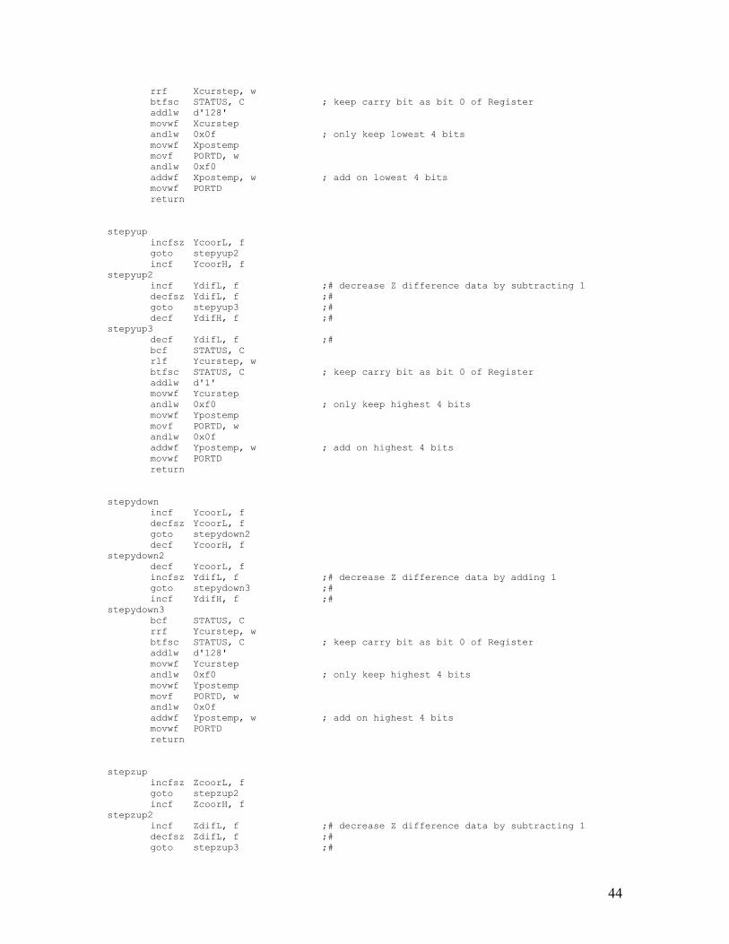
return motors_y_alone btfsc XYZdifFlags, 4 ; is it negative? goto motors_y_alone_neg motors_y_alone_pos call stepyup return motors_y_alone_neg call stepydown return motors_just_z btfsc XYZdifFlags, 5 ; is it negative? goto motors_just_z_neg motors_just_z_pos call stepzup call step_delay ; double delay time for Z axis return motors_just_z_neg call stepzdown call step_delay ; double delay time for Z axis return motors_all_zero ; Do Nothing! call p_ready ; Print "Ready..." to LCD call p_position ; print position bsf MillReady, 0 ; Mill Is done Working! return ;######################################### ;# Stepper Motor Routines # ;######################################### stepxup incfsz XcoorL, f goto stepxup2 incf XcoorH, f stepxup2 incf XdifL, f ;# decrease Z difference data by subtracting 1 decfsz XdifL, f ;# goto stepxup3 ;# decf XdifH, f ;# stepxup3 decf XdifL, f ;# bcf STATUS, C rlf Xcurstep, w btfsc STATUS, C ; keep carry bit as bit 0 of Register addlw d'1' movwf Xcurstep andlw 0x0f ; only keep lowest 4 bits movwf Xpostemp movf PORTD, w andlw 0xf0 addwf Xpostemp, w ; add on lowest 4 bits movwf PORTD return stepxdown incf XcoorL, f decfsz XcoorL, f goto stepxdown2 decf XcoorH, f stepxdown2 decf XcoorL, f incfsz XdifL, f ;# decrease Z difference data by adding 1 goto stepxdown3 ;# incf XdifH, f ;# stepxdown3 bcf STATUS, C
44
rrf Xcurstep, w btfsc STATUS, C ; keep carry bit as bit 0 of Register addlw d'128' movwf Xcurstep andlw 0x0f ; only keep lowest 4 bits movwf Xpostemp movf PORTD, w andlw 0xf0 addwf Xpostemp, w ; add on lowest 4 bits movwf PORTD return stepyup incfsz YcoorL, f goto stepyup2 incf YcoorH, f stepyup2 incf YdifL, f ;# decrease Z difference data by subtracting 1 decfsz YdifL, f ;# goto stepyup3 ;# decf YdifH, f ;# stepyup3 decf YdifL, f ;# bcf STATUS, C rlf Ycurstep, w btfsc STATUS, C ; keep carry bit as bit 0 of Register addlw d'1' movwf Ycurstep andlw 0xf0 ; only keep highest 4 bits movwf Ypostemp movf PORTD, w andlw 0x0f addwf Ypostemp, w ; add on highest 4 bits movwf PORTD return stepydown incf YcoorL, f decfsz YcoorL, f goto stepydown2 decf YcoorH, f stepydown2 decf YcoorL, f incfsz YdifL, f ;# decrease Z difference data by adding 1 goto stepydown3 ;# incf YdifH, f ;# stepydown3 bcf STATUS, C rrf Ycurstep, w btfsc STATUS, C ; keep carry bit as bit 0 of Register addlw d'128' movwf Ycurstep andlw 0xf0 ; only keep highest 4 bits movwf Ypostemp movf PORTD, w andlw 0x0f addwf Ypostemp, w ; add on highest 4 bits movwf PORTD return stepzup incfsz ZcoorL, f goto stepzup2 incf ZcoorH, f stepzup2 incf ZdifL, f ;# decrease Z difference data by subtracting 1 decfsz ZdifL, f ;# goto stepzup3 ;#

45
decf ZdifH, f ;# stepzup3 decf ZdifL, f ;# bcf STATUS, C rlf Zcurstep, w btfsc STATUS, C ; keep carry bit as bit 0 of Register addlw d'1' movwf Zcurstep andlw 0x0f ; only keep lowest 4 bits movwf Zpostemp movf PORTA, w andlw 0xf0 addwf Zpostemp, w ; add on lowest 4 bits movwf PORTA return stepzdown incf ZcoorL, f decfsz ZcoorL, f goto stepzdown2 decf ZcoorH, f stepzdown2 decf ZcoorL, f incfsz ZdifL, f ;# decrease Z difference data by adding 1 goto stepzdown3 ;# incf ZdifH, f ;# stepzdown3 bcf STATUS, C rrf Zcurstep, w btfsc STATUS, C ; keep carry bit as bit 0 of Register addlw d'128' movwf Zcurstep andlw 0x0f ; only keep lowest 4 bits movwf Zpostemp movf PORTA, w andlw 0xf0 addwf Zpostemp, w ; add on lowest 4 bits movwf PORTA return ;######################################### ;# MATH Routines # ;######################################### Find_Difs sub16x bcf STATUS, C ; clear the carry flag comf XcoorL,w ; calculate the 1's complement of the LSB for subtraction movwf XdifL comf XcoorH,w ; calculate the 1's complement of the MSB for subtraction movwf XdifH movf XdifL,w addlw 0x01 ; add 1 to the LSB 1st complement to get the 2's complement movwf XdifL btfsc STATUS,C ; test the carry flag, if a carry occurred incf XdifH,f ; add 1 to the MSB register if Carry occured add16x bcf STATUS,C movf XgotoH, w addwf XdifH, f bcf STATUS, C movf XgotoL, w addwf XdifL, f btfsc STATUS,C ; test the carry flag, if a carry occurred incf XdifH,f ; add 1 to the MSB register if Carry occured sub16y

46
bcf STATUS, C ; clear the carry flag comf YcoorL,w ; calculate the 1's complement of the LSB for subtraction movwf YdifL comf YcoorH,w ; calculate the 1's complement of the MSB for subtraction movwf YdifH movf YdifL,w addlw 0x01 ; add 1 to the LSB 1st complement to get the 2's complement movwf YdifL btfsc STATUS,C ; test the carry flag, if a carry occurred incf YdifH,f ; add 1 to the MSB register if Carry occured add16y bcf STATUS,C movf YgotoH, w addwf YdifH, f bcf STATUS, C movf YgotoL, w addwf YdifL, f btfsc STATUS,C ; test the carry flag, if a carry occurred incf YdifH,f ; add 1 to the MSB register if Carry occured sub16z bcf STATUS, C ; clear the carry flag comf ZcoorL,w ; calculate the 1's complement of the LSB for subtraction movwf ZdifL comf ZcoorH,w ; calculate the 1's complement of the MSB for subtraction movwf ZdifH movf ZdifL,w addlw 0x01 ; add 1 to the LSB 1st complement to get the 2's complement movwf ZdifL btfsc STATUS,C ; test the carry flag, if a carry occurred incf ZdifH,f ; add 1 to the MSB register if Carry occured add16z bcf STATUS,C movf ZgotoH, w addwf ZdifH, f bcf STATUS, C movf ZgotoL, w addwf ZdifL, f btfsc STATUS,C ; test the carry flag, if a carry occurred incf ZdifH,f ; add 1 to the MSB register if Carry occured return CalcDifBits clrf XYZdifFlags ; start XYZdifFlags from zero movf XdifL, w bcf STATUS, C sublw 0x00 btfss STATUS, C goto calcdifb2 ; X-L was not zero.. movf XdifH, w ; X-L was zero, check X-H bcf STATUS, C sublw 0x00 btfsc STATUS, C bsf XYZdifFlags, 0 ; X-H was zero, set to 1 calcdifb2 movf YdifL, w bcf STATUS, C sublw 0x00 btfss STATUS, C goto calcdifb3 ; Y-L was not zero.. movf YdifH, w ; Y-L was zero, check X-H bcf STATUS, C sublw 0x00 btfsc STATUS, C bsf XYZdifFlags, 1 ; Y-H was zero, set to 1 calcdifb3

47
movf ZdifL, w bcf STATUS, C sublw 0x00 btfss STATUS, C goto calcdifb4 ; Z-L was not zero.. movf ZdifH, w ; Z-L was zero, check X-H bcf STATUS, C sublw 0x00 btfsc STATUS, C bsf XYZdifFlags, 2 ; Z-H was zero, set to 1 calcdifb4 btfsc XdifH, 7 bsf XYZdifFlags, 3 ; Xdif is negative btfsc YdifH, 7 bsf XYZdifFlags, 4 ; Ydif is negative btfsc ZdifH, 7 bsf XYZdifFlags, 5 ; Zdif is negative btfss XYZdifFlags, 0 goto calcdifnotz btfss XYZdifFlags, 1 goto calcdifnotz bsf XYZdifFlags, 6 ; X and Y are both Zero btfsc XYZdifFlags, 2 bsf XYZdifFlags, 7 ; All numbers are Zero calcdifnotz return ;######################################### ;# LCD Commands # ;######################################### initialize movlw b'00110011' ; begin(still in 8-bit mode) call wr_setup movlw b'00110010' ; switch to 4-bit mode. Function Set. call wr_setup movlw b'00101000' ; another Function Set. call wr_setup movlw b'00001000' ;Display Off call wr_setup movlw b'00001111' ;Display On with Blinking Cursor call wr_setup movlw b'00001111' ;Display On with Blinking Cursor call wr_setup movlw b'00000110' ;Entry Mode call wr_setup movlw b'00101011' ;Fix Display.. makes display darker.
;N(3) = problem.. only one line!!! call wr_setup return LCD_firstline movlw b'10000000' ; move to 1st line call wr_setup return LCD_secondline movlw b'11000000' ; move to 2nd line call wr_setup return LCD_multispace ;set number of spaces desired in w register. movwf tmp3; LCD_msloop movlw b'00100000' ;write " " call wr_letter decfsz tmp3, f goto LCD_msloop return

48
wr_setup movwf tmp1 movf tmp1, w movwf tmp2 BCF tmp2, 0 ;use first nibble(d4-d7) BCF tmp2, 1 BCF tmp2, 2 BSF tmp2, 3 movf tmp2, w movwf PORTB ;send data (enable=1) call s_delay BCF PORTB, 3 ;end send, (enable=0) call s_delay rlf tmp1, w ;get next nibble (d0-d3) movwf tmp1 rlf tmp1, w movwf tmp1 rlf tmp1, w movwf tmp1 rlf tmp1, w movwf tmp2 BCF tmp2, 0 BCF tmp2, 1 BCF tmp2, 2 BSF tmp2, 3 movf tmp2, w movwf PORTB ;send data (enable=1) call s_delay BCF PORTB, 3 ;end send, (enable=0) call s_delay return wr_letter movwf tmp1 movf tmp1, w movwf tmp2 BCF tmp2, 0 ;use first nibble(d4-d7) BSF tmp2, 1 BCF tmp2, 2 BSF tmp2, 3 movf tmp2, w movwf PORTB ;send data (enable=1) call let_delay BCF PORTB, 3 ;end send, (enable=0) call let_delay rlf tmp1, w ;get next nibble (d0-d3) movwf tmp1 rlf tmp1, w movwf tmp1 rlf tmp1, w movwf tmp1 rlf tmp1, w movwf tmp2 BCF tmp2, 0 BSF tmp2, 1 BCF tmp2, 2 BSF tmp2, 3 movf tmp2, w movwf PORTB ;send data (enable=1) call let_delay BCF PORTB, 3 ;end send, (enable=0)
49
call let_delay return LCD_wr_bcd bsf TenK, 4 ;Convert decimal numbers into ASCII format for LCD bsf TenK, 5 bsf Thou, 4 bsf Thou, 5 bsf Hund, 4 bsf Hund, 5 bsf Tens, 4 bsf Tens, 5 bsf Ones, 4 bsf Ones, 5 movf TenK, w call wr_letter movf Thou, w call wr_letter movf Hund, w call wr_letter movf Tens, w call wr_letter movf Ones, w call wr_letter retlw 0 ;######################################### ;# LCD Write Routines # ;######################################### p_ready call LCD_firstline movlw d'8' call LCD_multispace movlw a'R' call wr_letter movlw a'e' call wr_letter movlw a'a' call wr_letter movlw a'd' call wr_letter movlw a'y' call wr_letter movlw a'.' call wr_letter movlw a'.' call wr_letter movlw a'.' call wr_letter movlw d'8' call LCD_multispace call LCD_secondline movlw d'24' call LCD_multispace return p_position call LCD_secondline movlw a'X' call wr_letter movlw a'=' call wr_letter movf XcoorL, w movwf NumL movf XcoorH, w movwf NumH call BCD ; convert to Decimal call LCD_wr_bcd ;print out BCD of X position movlw a' '

50
call wr_letter movlw a'Y' call wr_letter movlw a'=' call wr_letter movf YcoorL, w movwf NumL movf YcoorH, w movwf NumH call BCD ; convert to Decimal call LCD_wr_bcd ;print out BCD of Y position movlw a' ' call wr_letter movlw a'Z' call wr_letter movlw a'=' call wr_letter movf ZcoorL, w movwf NumL movf ZcoorH, w movwf NumH call BCD ; convert to Decimal call LCD_wr_bcd ;print out BCD of Z position movlw a' ' call wr_letter return p_going call LCD_firstline movlw d'8' call LCD_multispace movlw a'G' call wr_letter movlw a'o' call wr_letter movlw a'i' call wr_letter movlw a'n' call wr_letter movlw a'g' call wr_letter movlw a' ' call wr_letter movlw a't' call wr_letter movlw a'o' call wr_letter movlw a'.' call wr_letter movlw a'.' call wr_letter movlw a'.' call wr_letter movlw d'5' call LCD_multispace call LCD_secondline movlw d'24' call LCD_multispace return p_gotopos call LCD_secondline movlw a'X' call wr_letter movlw a'=' call wr_letter movf XgotoL, w movwf NumL movf XgotoH, w movwf NumH call BCD ; convert to Decimal

51
call LCD_wr_bcd ;print out BCD of X position movlw a' ' call wr_letter movlw a'Y' call wr_letter movlw a'=' call wr_letter movf YgotoL, w movwf NumL movf YgotoH, w movwf NumH call BCD ; convert to Decimal call LCD_wr_bcd ;print out BCD of Y position movlw a' ' call wr_letter movlw a'Z' call wr_letter movlw a'=' call wr_letter movf ZgotoL, w movwf NumL movf ZgotoH, w movwf NumH call BCD ; convert to Decimal call LCD_wr_bcd ;print out BCD of Z position movlw a' ' call wr_letter return p_error call LCD_firstline movlw d'8' call LCD_multispace movlw a'*' call wr_letter movlw a'*' call wr_letter movlw a' ' call wr_letter movlw a'E' call wr_letter movlw a'r' call wr_letter movlw a'r' call wr_letter movlw a'o' call wr_letter movlw a'r' call wr_letter movlw a' ' call wr_letter movlw a'*' call wr_letter movlw a'*' call wr_letter movlw d'5' call LCD_multispace call LCD_secondline movlw d'24' call LCD_multispace return ;######################################### ;# Binary Converted Decimal # ;######################################### BCD ;input ;=A3*163 + A2*162 + A1*161 + A0*160 ;=A3*4096 + A2*256 + A1*16 + A0 ;NumH EQU AD3M ;A3*16+A2 ;NumL EQU AD3L ;A1*16+A0

52
;share variables ;=B4*104 + B3*103 + B2*102 + B1*101 + B0*100 ;=B4*10000 + B3*1000 + B2*100 + B1*10 + B0 ;TenK EQU LOOPER ;B4 ;Thou EQU D2 ;B3 ;Hund EQU D1 ;B2 ;Tens EQU R2 ;B1 ;Ones EQU R1 ;B0 swapf NumH,w ;w = A2*16+A3 andlw 0x0F ;w = A3 addlw 0xF0 ;w = A3-16 movwf Thou ;B3 = A3-16 addwf Thou,f ;B3 = 2*(A3-16) = 2A3 - 32 addlw d'226' ;w = A3-16 - 30 = A3-46 movwf Hund ;B2 = A3-46 addlw d'50' ;w = A3-46 + 50 = A3+4 movwf Ones ;B0 = A3+4 movf NumH,w ;w = A3*16+A2 andlw 0x0F ;w = A2 addwf Hund,f ;B2 = A3-46 + A2 = A3+A2-46 addwf Hund,f ;B2 = A3+A2-46 + A2 = A3+2A2-46 addwf Ones,f ;B0 = A3+4 + A2 = A3+A2+4 addlw d'233' ;w = A2 - 23 movwf Tens ;B1 = A2-23 addwf Tens,f ;B1 = 2*(A2-23) addwf Tens,f ;B1 = 3*(A2-23) = 3A2-69 (Doh! thanks NG) swapf NumL,w ;w = A0*16+A1 andlw 0x0F ;w = A1 addwf Tens,f ;B1 = 3A2-69 + A1 = 3A2+A1-69 range -69...-9 addwf Ones,f ;B0 = A3+A2+4 + A1 = A3+A2+A1+4
;and Carry = 0 (thanks NG) rlf Tens,f ;B1 = 2*(3A2+A1-69) + C = 6A2+2A1-138 and
;Carry is now 1 as tens register had to be negitive rlf Ones,f ;B0 = 2*(A3+A2+A1+4) + C = 2A3+2A2+2A1+9
;(+9 not +8 due to the carry from prev line, Thanks NG) comf Ones,f ;B0 = ~(2A3+2A2+2A1+9) = -2A3-2A2-2A1-10
;(ones complement plus 1 is twos complement. Thanks SD) rlf Ones,f ;B0 = 2*(-2A3-2A2-2A1-10) = -4A3-4A2-4A1-20 movf NumL,w ;w = A1*16+A0 andlw 0x0F ;w = A0 addwf Ones,f ;B0 = -4A3-4A2-4A1-20 + A0 = A0-4(A3+A2+A1)-20
;range -215...-5 Carry=0 rlf Thou,f ;B3 = 2*(2A3 - 32) = 4A3 - 64 movlw 0x07 ;w = 7 movwf TenK ;B4 = 7 movlw d'10' ;w = 10 Lb1: ;do addwf Ones,f ; B0 += 10 decf Tens,f ; B1 -= 1 btfss 3,0 goto Lb1 ; while B0 < 0 Lb2: ;do addwf Tens,f ; B1 += 10 decf Hund,f ; B2 -= 1 btfss 3,0 goto Lb2 ; while B1 < 0 Lb3: ;do addwf Hund,f ; B2 += 10 decf Thou,f ; B3 -= 1 btfss 3,0 goto Lb3 ; while B2 < 0 Lb4: ;do addwf Thou,f ; B3 += 10 decf TenK,f ; B4 -= 1 btfss 3,0

53
goto Lb4 ; while B3 < 0 retlw 0 ;######################################### ;# Delay Routines # ;######################################### ;### s_delay is used to allow the correct amount of time to ; pass when instructions are sent to the LCD. ; Setup_Delay = 0.005 seconds ; Clock frequency = 20 MHz ; Actual delay = 0.005 seconds = 25000 cycles ; Error = 0 % s_delay ;24921 cycles movlw 0x59 movwf d1 s_delay_00 movlw 0x5c movwf d2 s_delay_01 decfsz d2, f goto s_delay_01 decfsz d1, f goto s_delay_00 ;73 cycles movlw 0x18 movwf d1 s_delay_10 decfsz d1, f goto s_delay_10 ;2 cycles nop nop ;4 cycles (including call) return ; Let_Delay = 0.0001 seconds ; Clock frequency = 20 MHz ; Actual delay = 0.0001 seconds = 500 cycles ; Error = 0 % let_delay ;496 cycles movlw 0xa5 movwf d1 let_delay_00 decfsz d1, f goto let_delay_00 ;4 cycles (including call) return ; Delay = 1 seconds ; Clock frequency = 20 MHz ; Actual delay = 1 seconds = 5000000 cycles ; Error = 0 % Delay ;4963001 cycles movlw 0x7d movwf d1 Delay_00 movlw 0x64 movwf d2 Delay_01 movlw 0x83 movwf d3 Delay_02 decfsz d3, f goto Delay_02 decfsz d2, f
54
goto Delay_01 decfsz d1, f goto Delay_00 ;36981 cycles movlw 0x56 movwf d1 Delay_10 movlw 0x8e movwf d2 Delay_11 decfsz d2, f goto Delay_11 decfsz d1, f goto Delay_10 ;13 cycles movlw 0x04 movwf d1 Delay_20 decfsz d1, f goto Delay_20 ;1 cycle nop ;4 cycles (including call) return ;### step_delay is used to create the delay between stepper motor cycles. ; Delay = 0.015 seconds ; Clock frequency = 20 MHz ; Actual delay = 0.015 seconds = 75000 cycles ; Error = 0 % step_delay ;74993 cycles movlw 0x96 movwf d1 movlw 0x3B movwf d2 step_delay_0 decfsz d1, f goto $+2 decfsz d2, f goto step_delay_0 ;3 cycles goto $+1 nop ;4 cycles (including call) return ; Delay = 1248 instruction cycles ; Clock frequency = 20 MHz ; Actual delay = 0.0002496 seconds = 1248 cycles ; Error = 0 % sub_delay ;1243 cycles return movlw 0xF8 movwf d1 movlw 0x01 movwf d2 sub_delay_0 decfsz d1, f goto $+2 decfsz d2, f goto sub_delay_0 ;1 cycle nop ;4 cycles (including call) return END

55
Appendix C: PIC16F877 Timing Diagram
Inst. = Instruction Byte (currently not used)
XMSB = X position Most Significant Byte XLSB = X position Least Significant Byte YMSB = Y position Most Significant Byte YLSB = Y position Least Significant Byte ZMSB = Z position Most Significant Byte ZLSB = Z position Least Significant Byte
MillReady is driven High by the PIC16F877 when it is ready for a new mill position. The R31JP can then set the appropriate Data byte on the Databus. To clock in the data, the Enable line is pulled high by the R31JP for a minimum of 1.0 uSeconds. The Enable line can then be lower and after a delay of Twait (greater than 1.8 uSeconds), the process can be repeated to clock in the remaining Data bytes.
Enable
Data
MillReady
Inst. XMSB XLSB YMSB YLSB ZMSB ZLSB
Twait TE
Twait > 1.0 uSec TE > 1.8 uSec
Milling…

56
Appendix D: C++ Code (This is not the full program as there are many other files that control the visual layout, linking, etc..) #include <vcl.h> #pragma hdrstop #include "Unit1.h" #include "Unit2.h" //--------------------------------------------------------------------------- #pragma package(smart_init) #pragma resource "*.dfm" TForm1 *Form1; //--------------------------------------------------------------------------- __fastcall TForm1::TForm1(TComponent* Owner) : TForm(Owner) { // Setup Stepper Motor Info Here ThreadsperInch = 18; Stepsperrev = 48; currentcoorx = 0; currentcoory = 0; plotterup = 1; stepvisualize = 0; ComboBox1->ItemIndex = 3; ComboBox2->ItemIndex = 3; } //--------------------------------------------------------------------------- void __fastcall TForm1::Button1Click(TObject *Sender) { int hpglx = 0; int hpgly = 0; AnsiString temp = 0; temp = Edit1->Text * 1016; hpglx = atoi(temp.c_str()); //1016 Plotter Units per inch temp = Edit2->Text * 1016; hpgly = atoi(temp.c_str()); //1016 Plotter Units per inch currentcoorx = hpglx; currentcoory = hpgly; Memo1->Lines->Text = Memo1->Lines->Text + "PA" + currentcoorx + "," + currentcoory + ";PU;\r\n"; Memo1->Perform(EM_LINESCROLL,0 ,Memo1->Lines->Count); } //--------------------------------------------------------------------------- void __fastcall TForm1::Button2Click(TObject *Sender) { int hpglx = 0; int hpgly = 0; AnsiString temp = 0; temp = Edit1->Text * 1016; hpglx = atoi(temp.c_str()); //1016 Plotter Units per inch temp = Edit2->Text * 1016; hpgly = atoi(temp.c_str()); //1016 Plotter Units per inch currentcoorx = hpglx; currentcoory = hpgly; Memo1->Lines->Text = Memo1->Lines->Text + "PA" + currentcoorx + "," + currentcoory + ";PD;\r\n"; Memo1->Perform(EM_LINESCROLL,0 ,Memo1->Lines->Count); } //--------------------------------------------------------------------------- void __fastcall TForm1::Button4click(TObject *Sender) { Label12->Caption = "Starting"; Label12->Update(); zoom = 0; Button4->Caption = "Please Wait"; makegrid(); PaintBox1->Canvas->Pen->Color = 0x0000ff; //Red Pen color Label10->Caption = ""; String input = Memo1->Text; Label12->Caption = "Parsing: 1st Pass"; Label12->Update(); stringreplace(input,"\r",""); // Get rid of carraige returns and line breaks Label12->Caption = "Parsing: 2nd Pass"; Label12->Update(); stringreplace(input,"\n",""); Label12->Caption = "Computing"; Label12->Update(); // We are now left a single line, seperated by ";" and // each entry beginning with a letter. // A=position, U=plotter Up, D=Plotter Down for(int q=0; q < 10000; q++){ // clear out result array. result[q] = ""; }

57
Split(input,';',result); // result is an array of data example.. (A300,500; D; A500,500; U) stepvisualize = 0; plotterup = 1; int index=0; float divider; divider = (Stepsperrev * ThreadsperInch); divider = 1016/divider; // divider = number to divide HPGL by... LoadAddress = 0; kmfFILE = ""; //Start Output file from scratch result[0].Delete(1,1); // get rid of first character while(index<9999){ result[index+1].Delete(1,1); // get rid of first character if(result[index].Pos("A")){ //Move Plotter Position int xreturn; int yreturn; splitXY(result[index], xreturn, yreturn); // Output to KMF Array !! if(xreturn < 0 || yreturn < 0){ Label10->Caption = "Error! Negative Position Encountered @ Instruction:"; Label10->Caption = Label10->Caption + index; kmfFILE += "-#ERROR#-\r\n"; if(xreturn < 0){ xreturn = 0; } if(yreturn < 0){ yreturn = 0; } int negpos = Memo1->Text.Pos("-"); Memo1->SelStart = negpos-1; Memo1->SelLength = 1; Memo1->SetFocus(); } if(PenNumber == ComboBox1->ItemIndex){ int checksum; char *chAdd=result[index+1].c_str(); //look at next piece of data
//for Up/Down commands int Instruction; switch(*chAdd){ case 'A': Instruction = 1; break; case 'U': Instruction = 2; break; case 'D': int Ztravel = Edit4->Text * 10000; Instruction = (ThreadsperInch * Stepsperrev * Ztravel)/10000; break; } kmfFILE += ":05"; // for Intel Hex File, :=RecordMark, 05=5
// bytes of Info kmfFILE += IntToHex(LoadAddress,4); // Load Address kmfFILE += "00"; // Store as type "data" if(Instruction < 16){ kmfFILE += "0" + IntToHex(Instruction,1); // Append the Instruction character; } if(Instruction >= 16 && Instruction < 256){ kmfFILE += IntToHex(Instruction,2); // Append the Instruction character; } if(Instruction >=256){ kmfFILE += "ff"; // Append the Instruction character; Instruction = 255; Label10->Caption = "Error! Z Axis Travel Greater than "; float extreme = (255 * 1000)/ (Stepsperrev * ThreadsperInch); Label10->Caption = Label10->Caption + extreme; Label10->Caption = Label10->Caption + " (Thousandths of an Inch)"; } kmfFILE += IntToHex(int(xreturn/divider),4); // print x Hex values kmfFILE += IntToHex(int(yreturn/divider),4); // print y Hex Values checksum = (5 + Instruction + int(LoadAddress/256) + int(LoadAddress%256) + int((int(xreturn/divider))/256) + int((int(xreturn/divider))%256) + int((int(yreturn/divider))/256) + int((int(yreturn/divider))%256)); checksum = checksum % 256; // only keep one byte of information. (LSB) checksum = 256 - checksum; checksum = checksum % 256; kmfFILE += IntToHex(checksum,2); kmfFILE += "\r\n"; // newline LoadAddress = LoadAddress + 5; } // End KMF Array Operations xreturn = xreturn / 10.16; yreturn = yreturn / 10.16; if(plotterup == 1){ // plotter is up, do not draw. PaintBox1->Canvas->MoveTo(xreturn,(800-yreturn)); currentcoorx = xreturn; currentcoory = (800-yreturn); } if(plotterup == 0){ //plotter is down, draw line PaintBox1->Canvas->LineTo(xreturn,(800-yreturn)); currentcoorx = xreturn;

58
currentcoory = (800-yreturn); } } if(result[index].Pos("U")){ // Plotter Up plotterup = 1; } if(result[index].Pos("D")){ // Plotter Down plotterup = 0; if(PenNumber == 1 || PenNumber == 2 || PenNumber == 5){ PaintBox1->Canvas->Ellipse(currentcoorx+2, currentcoory+2,currentcoorx-2, currentcoory-2); } } if(result[index].Pos("P")){ String holder = result[index]; holder.Delete(1,1); // get rid of P PenNumber = atoi(holder.c_str()); switch(atoi(holder.c_str())){ case 0: PaintBox1->Canvas->Pen->Color = 0x007700; break; case 1: PaintBox1->Canvas->Pen->Color = 0xff0000; // Main Drill break; case 2: PaintBox1->Canvas->Pen->Color = 0x007700; //drill break; case 3: PaintBox1->Canvas->Pen->Color = 0x0000ff; //Main Trace break; case 4: PaintBox1->Canvas->Pen->Color = 0x007700; //?? break; case 5: PaintBox1->Canvas->Pen->Color = 0x007700; //drill break; case 6: PaintBox1->Canvas->Pen->Color = 0x007700; //short drill? break; case 7: PaintBox1->Canvas->Pen->Color = 0x007700; // trace? break; default: PaintBox1->Canvas->Pen->Color = 0x000000; // else - black break; } } index++; } kmfFILE += ":00000001FF"; // Close kmfFIle with and End byte Memo2->Text = kmfFILE; Button4->Caption = "ReRun HPGL"; Button8->Visible=true; Button6->Visible=true; Button7->Visible=true; Button9->Visible=true; Button11->Visible=true; Edit3->Visible=true; Label9->Visible=true; StaticText2->Visible = false; Label12->Caption = ""; Label12->Update(); } //--------------------------------------------------------------------------- void TForm1::makegrid() { // Make a 1" x 1" grid for reference long holdx, holdy; holdx = PaintBox1->Canvas->PenPos.x; holdy = PaintBox1->Canvas->PenPos.y; PaintBox1->Refresh(); PaintBox1->Canvas->MoveTo(holdx,holdy); // keep original cooridinates. PaintBox1->Canvas->Pen->Color = 0xffffff; PaintBox1->Canvas->MoveTo(0,800); PaintBox1->Canvas->LineTo(800,800); PaintBox1->Canvas->MoveTo(0,700); PaintBox1->Canvas->LineTo(800,700); PaintBox1->Canvas->MoveTo(0,600); PaintBox1->Canvas->LineTo(800,600); PaintBox1->Canvas->MoveTo(0,500); PaintBox1->Canvas->LineTo(800,500); PaintBox1->Canvas->MoveTo(0,400); PaintBox1->Canvas->LineTo(800,400); PaintBox1->Canvas->MoveTo(0,300); PaintBox1->Canvas->LineTo(800,300); PaintBox1->Canvas->MoveTo(0,200); PaintBox1->Canvas->LineTo(800,200); PaintBox1->Canvas->MoveTo(0,100); PaintBox1->Canvas->LineTo(800,100); PaintBox1->Canvas->MoveTo(0,0);
59
PaintBox1->Canvas->LineTo(800,0); PaintBox1->Canvas->MoveTo(0,0); PaintBox1->Canvas->LineTo(0,800); PaintBox1->Canvas->MoveTo(100,0); PaintBox1->Canvas->LineTo(100,800); PaintBox1->Canvas->MoveTo(200,0); PaintBox1->Canvas->LineTo(200,800); PaintBox1->Canvas->MoveTo(300,0); PaintBox1->Canvas->LineTo(300,800); PaintBox1->Canvas->MoveTo(400,0); PaintBox1->Canvas->LineTo(400,800); PaintBox1->Canvas->MoveTo(500,0); PaintBox1->Canvas->LineTo(500,800); PaintBox1->Canvas->MoveTo(600,0); PaintBox1->Canvas->LineTo(600,800); PaintBox1->Canvas->MoveTo(700,0); PaintBox1->Canvas->LineTo(700,800); PaintBox1->Canvas->MoveTo(800,0); PaintBox1->Canvas->LineTo(800,800); PaintBox1->Canvas->Pen->Color = 0x0000ff; PaintBox1->Update(); } void __fastcall TForm1::Button5click(TObject *Sender) { long holdx, holdy; holdx = PaintBox1->Canvas->PenPos.x; holdy = PaintBox1->Canvas->PenPos.y; PaintBox1->Refresh(); makegrid(); PaintBox1->Canvas->MoveTo(holdx,holdy); // keep original cooridinates. } //--------------------------------------------------------------------------- void __fastcall TForm1::Button3Click(TObject *Sender) { int hpglx = 0; int hpgly = 0; AnsiString temp = 0; temp = Edit1->Text * 1016; hpglx = atoi(temp.c_str()); //1016 Plotter Units per inch temp = Edit2->Text * 1016; hpgly = atoi(temp.c_str()); //1016 Plotter Units per inch Memo1->Lines->Text = Memo1->Lines->Text + "PA" + hpglx + "," + hpgly + ";\r\n"; currentcoorx = hpglx; currentcoory = hpgly; Memo1->Perform(EM_LINESCROLL,0 ,Memo1->Lines->Count); // Scroll to bottom } //--------------------------------------------------------------------------- void __fastcall TForm1::PaintBox1MouseMove(TObject *Sender, TShiftState Shift, int X, int Y) { zoomdifx = X; zoomdify = Y - 800; X = X + 5; //center around 1/16" away Y = Y - 5; Y = 800 - Y; //fix cooridinate system int decx; int decy; decx = X % 100; decy = Y % 100; decx = decx / 12.5; decy = decy / 12.5; decx = decx * 125; // snap to 1/8" decy = decy * 125; X = X / 100; Y = Y / 100; gridposition->Caption = "X = "; gridposition->Caption = gridposition->Caption + X; gridposition->Caption = gridposition->Caption + "." + decx; gridposition->Caption = gridposition->Caption + ", Y = " + Y; gridposition->Caption = gridposition->Caption + "." + decy; if(result[0] != "" && Shift.Contains(ssLeft)){ if(zoom != 0){ Edit1->Text = 0; Edit2->Text = 0; Button11->Caption = "Redrawing x2"; makegrid(); stepvisualize = 0; plotterup = 1; int index=0; while(index<10000){ if(result[index].Pos("A")){ //Move Plotter Position int xreturn; int yreturn; splitXY(result[index], xreturn, yreturn); xreturn = xreturn / 10.16; yreturn = yreturn / 10.16; if(plotterup == 1){ // plotter is up, do not draw. PaintBox1->Canvas->MoveTo(xreturn * 2 - zoomdifx,(800-(yreturn * 2)-zoomdify));

60
currentcoorx = xreturn * 2 - zoomdifx; currentcoory = (800-(yreturn * 2) - zoomdify); } if(plotterup == 0){ //plotter is down, draw line PaintBox1->Canvas->LineTo(xreturn * 2 - zoomdifx,(800-(yreturn * 2)-zoomdify)); currentcoorx = xreturn * 2 - zoomdifx; currentcoory = (800-(yreturn * 2) - zoomdify); } } if(result[index].Pos("U")){ // Plotter Up plotterup = 1; } if(result[index].Pos("D")){ // Plotter Down plotterup = 0; if(PenNumber == 1 || PenNumber == 2 || PenNumber == 5){ PaintBox1->Canvas->Ellipse(currentcoorx+2, currentcoory+2,currentcoorx-2, currentcoory-2); } } if(result[index].Pos("P")){ String holder = result[index]; holder.Delete(1,1); // get rid of P PenNumber = atoi(holder.c_str()); switch(atoi(holder.c_str())){ case 0: PaintBox1->Canvas->Pen->Color = 0x007700; break; case 1: PaintBox1->Canvas->Pen->Color = 0xff0000; // Main Drill break; case 2: PaintBox1->Canvas->Pen->Color = 0x007700; //drill break; case 3: PaintBox1->Canvas->Pen->Color = 0x0000ff; //Main Trace break; case 4: PaintBox1->Canvas->Pen->Color = 0x007700; //?? break; case 5: PaintBox1->Canvas->Pen->Color = 0x007700; //drill break; case 6: PaintBox1->Canvas->Pen->Color = 0x007700; //short drill? break; case 7: PaintBox1->Canvas->Pen->Color = 0x007700; // trace? break; default: PaintBox1->Canvas->Pen->Color = 0x000000; // else - black break; } } index++; } Button11->Caption = "Zoom x 2"; } } } //--------------------------------------------------------------------------- void __fastcall TForm1::PaintBox1MouseDown(TObject *Sender, TMouseButton Button, TShiftState Shift, int X, int Y) { //zoomdifx = X; //zoomdify = Y - 800; if(zoom == 0){ X = X + 5; //center around 1/16" away Y = Y - 5; Y = 800 - Y; //fix cooridinate system int decx; int decy; decx = X % 100; decy = Y % 100; decx = decx / 12.5; decy = decy / 12.5; decx = decx * 125; // snap to 1/8" decy = decy * 125; X = X / 100; Y = Y / 100; gridposition->Caption = "X = "; gridposition->Caption = gridposition->Caption + X; gridposition->Caption = gridposition->Caption + "." + decx; gridposition->Caption = gridposition->Caption + ", Y = " + Y; gridposition->Caption = gridposition->Caption + "." + decy; // Write to Cooridinate Boxes.. Edit1->Text = X; Edit1->Text = Edit1->Text + "."; Edit1->Text = Edit1->Text + decx; Edit2->Text = Y; Edit2->Text = Edit2->Text + "."; Edit2->Text = Edit2->Text + decy; // Move Position Shape Icon. int p;
61
p = X * 100 + (decx / 10) - 3; Shape2->Left = p; p = (800 - (Y * 100 + (decy / 10))) - 2; Shape2->Top = p; } if(result[0] != ""){ if(zoom != 0){ Edit1->Text = 0; Edit2->Text = 0; Button11->Caption = "Redrawing x2"; makegrid(); stepvisualize = 0; plotterup = 1; int index=0; while(index<10000){ if(result[index].Pos("A")){ //Move Plotter Position int xreturn; int yreturn; splitXY(result[index], xreturn, yreturn); xreturn = xreturn / 10.16; yreturn = yreturn / 10.16; if(plotterup == 1){ // plotter is up, do not draw. PaintBox1->Canvas->MoveTo(xreturn * 2 - zoomdifx,(800-(yreturn * 2)-zoomdify)); currentcoorx = xreturn * 2 - zoomdifx; currentcoory = (800-(yreturn * 2) - zoomdify); } if(plotterup == 0){ //plotter is down, draw line PaintBox1->Canvas->LineTo(xreturn * 2 - zoomdifx,(800-(yreturn * 2)-zoomdify)); currentcoorx = xreturn * 2 - zoomdifx; currentcoory = (800-(yreturn * 2) - zoomdify); } } if(result[index].Pos("U")){ // Plotter Up plotterup = 1; } if(result[index].Pos("D")){ // Plotter Down plotterup = 0; if(PenNumber == 1 || PenNumber == 2 || PenNumber == 5){ PaintBox1->Canvas->Ellipse(currentcoorx+2, currentcoory+2,currentcoorx-2, currentcoory-2); } } if(result[index].Pos("P")){ String holder = result[index]; holder.Delete(1,1); // get rid of P PenNumber = atoi(holder.c_str()); switch(atoi(holder.c_str())){ case 0: PaintBox1->Canvas->Pen->Color = 0x007700; break; case 1: PaintBox1->Canvas->Pen->Color = 0xff0000; // Main Drill break; case 2: PaintBox1->Canvas->Pen->Color = 0x007700; //drill break; case 3: PaintBox1->Canvas->Pen->Color = 0x0000ff; //Main Trace break; case 4: PaintBox1->Canvas->Pen->Color = 0x007700; //?? break; case 5: PaintBox1->Canvas->Pen->Color = 0x007700; //drill break; case 6: PaintBox1->Canvas->Pen->Color = 0x007700; //short drill? break; case 7: PaintBox1->Canvas->Pen->Color = 0x007700; // trace? break; default: PaintBox1->Canvas->Pen->Color = 0x000000; // else - black break; } } index++; } Button11->Caption = "Zoom x 2"; } } } //--------------------------------------------------------------------------- void __fastcall TForm1::Edit1Change(TObject *Sender) { int q; if(Edit1->Text >= 0){ q = (Edit1->Text * 100) - 3; Shape2->Left = q; }

62
} //--------------------------------------------------------------------------- void __fastcall TForm1::Edit2Change(TObject *Sender) { int q; if(Edit2->Text >= 0){ q = (Edit2->Text * 100); q = (800 - q) - 2; Shape2->Top = q; } } //--------------------------------------------------------------------------- void TForm1::stringreplace(String & WorkOn, String Find, String Replacer) { int len = Find.Length(); int loc = WorkOn.Pos(Find); //String WorkOnHolder = WorkOn; while (loc) { //WorkOnHolder.Delete(loc, len); // using a seperate WorkOnHolder allows the replacing WorkOn.Delete(loc, len); // string to include something in the find string. WorkOn.Insert(Replacer, loc); loc = WorkOn.Pos(Find); //loc = WorkOnHolder.Pos(Find); } } void TForm1::Split(String WorkOn, const char Splitter, String Array[10000]) { char *chAdd=WorkOn.c_str(); int index=0; while (index<10000) { while( ( *chAdd!='\0' )&& ( *chAdd!=Splitter ) ) { // Read a string until a Splitter or end of string is encountered Array[ index ]+=*chAdd; // Append the character ++chAdd; } if( *chAdd!='\0' ) ++chAdd; // If we ended at the Splitter, jump over it ++index; } } void TForm1::splitXY(String WorkOn, int & xreturn, int & yreturn) //grab X and Y coors from comma split AnsiString. { WorkOn.Delete(1, 1); //get rid of first character (A) int delimit = WorkOn.Pos(","); String temp; temp = WorkOn; xreturn = atoi(temp.Delete(delimit,10).c_str()); yreturn = atoi(WorkOn.Delete(1,delimit).c_str()); } void __fastcall TForm1::Button6Click(TObject *Sender) // STEP Visualization Routine { Button6->Caption = "Please Wait"; if(result[stepvisualize].Pos("A")){ //Move Plotter Position int xreturn; int yreturn; splitXY(result[stepvisualize], xreturn, yreturn); xreturn = xreturn / 10.16; yreturn = yreturn / 10.16; if(plotterup == 1){ // plotter is up, do not draw. PaintBox1->Canvas->MoveTo(xreturn,(800-yreturn)); currentcoorx = xreturn; currentcoory = (800-yreturn); } if(plotterup == 0){ //plotter is down, draw line PaintBox1->Canvas->LineTo(xreturn,(800-yreturn)); currentcoorx = xreturn; currentcoory = (800-yreturn); } } if(result[stepvisualize].Pos("U")){ // Plotter Up plotterup = 1; } if(result[stepvisualize].Pos("D")){ // Plotter Down plotterup = 0; if(PenNumber == 1 || PenNumber == 2 || PenNumber == 5){ PaintBox1->Canvas->Ellipse(currentcoorx+2, currentcoory+2,currentcoorx-2, currentcoory-2); } } if(result[stepvisualize].Pos("P")){ String holder = result[stepvisualize]; holder.Delete(1,1); // get rid of P PenNumber = atoi(holder.c_str()); switch(atoi(holder.c_str())){ case 0: PaintBox1->Canvas->Pen->Color = 0x007700; break; case 1:

63
PaintBox1->Canvas->Pen->Color = 0xff0000; // Main Drill break; case 2: PaintBox1->Canvas->Pen->Color = 0x007700; //drill break; case 3: PaintBox1->Canvas->Pen->Color = 0x0000ff; //Main Trace break; case 4: PaintBox1->Canvas->Pen->Color = 0x007700; //?? break; case 5: PaintBox1->Canvas->Pen->Color = 0x007700; //drill break; case 6: PaintBox1->Canvas->Pen->Color = 0x007700; //short drill? break; case 7: PaintBox1->Canvas->Pen->Color = 0x007700; // trace? break; default: PaintBox1->Canvas->Pen->Color = 0x000000; // else - black break; } } stepvisualize++; if(stepvisualize >= 10000) stepvisualize = 0; Edit3->Text = stepvisualize; Button6->Caption = "Step Visualize"; } //--------------------------------------------------------------------------- void __fastcall TForm1::Button7Click(TObject *Sender) { plotterup = 1; stepvisualize = 0; Edit3->Text = stepvisualize; } //--------------------------------------------------------------------------- void __fastcall TForm1::Button8Click(TObject *Sender) // Redraw Entire Layout { StaticText2->Visible = false; zoom = 0; Button8->Caption = "Redrawing"; makegrid(); stepvisualize = 0; plotterup = 1; int index=0; while(index<10000){ if(result[index].Pos("A")){ //Move Plotter Position int xreturn; int yreturn; splitXY(result[index], xreturn, yreturn); xreturn = xreturn / 10.16; yreturn = yreturn / 10.16; if(plotterup == 1){ // plotter is up, do not draw. PaintBox1->Canvas->MoveTo(xreturn,(800-yreturn)); currentcoorx = xreturn; currentcoory = (800-yreturn); } if(plotterup == 0){ //plotter is down, draw line PaintBox1->Canvas->LineTo(xreturn,(800-yreturn)); currentcoorx = xreturn; currentcoory = (800-yreturn); } } if(result[index].Pos("U")){ // Plotter Up plotterup = 1; } if(result[index].Pos("D")){ // Plotter Down plotterup = 0; if(PenNumber == 1 || PenNumber == 2 || PenNumber == 5){ PaintBox1->Canvas->Ellipse(currentcoorx+2, currentcoory+2,currentcoorx-2, currentcoory-2); } } if(result[index].Pos("P")){ String holder = result[index]; holder.Delete(1,1); // get rid of P PenNumber = atoi(holder.c_str()); switch(atoi(holder.c_str())){ case 0: PaintBox1->Canvas->Pen->Color = 0x007700; break; case 1: PaintBox1->Canvas->Pen->Color = 0xff0000; // Main Drill break; case 2: PaintBox1->Canvas->Pen->Color = 0x007700; //drill break; case 3: PaintBox1->Canvas->Pen->Color = 0x0000ff; //Main Trace break; case 4:

64
PaintBox1->Canvas->Pen->Color = 0x007700; //?? break; case 5: PaintBox1->Canvas->Pen->Color = 0x007700; //drill break; case 6: PaintBox1->Canvas->Pen->Color = 0x007700; //short drill? break; case 7: PaintBox1->Canvas->Pen->Color = 0x007700; // trace? break; default: PaintBox1->Canvas->Pen->Color = 0x000000; // else - black break; } } index++; } Button8->Caption = "Redraw Route"; Button11->Visible=true; } //--------------------------------------------------------------------------- void __fastcall TForm1::Button9Click(TObject *Sender) { stepvisualize = atoi(Edit3->Text.c_str()); } //--------------------------------------------------------------------------- void __fastcall TForm1::Button10Click(TObject *Sender) { Memo1->Lines->Text = Memo1->Lines->Text + "SP" + ComboBox2->ItemIndex + ";\r\n"; Memo1->Perform(EM_LINESCROLL,0 ,Memo1->Lines->Count); } //--------------------------------------------------------------------------- void __fastcall TForm1::Button11Click(TObject *Sender) { StaticText2->Visible = true; Button11->Visible=false; makegrid(); zoom = 1; Button11->Caption = "Redrawing x2"; stepvisualize = 0; plotterup = 1; int index=0; while(index<10000){ if(result[index].Pos("A")){ //Move Plotter Position int xreturn; int yreturn; splitXY(result[index], xreturn, yreturn); xreturn = xreturn / 10.16; yreturn = yreturn / 10.16; if(plotterup == 1){ // plotter is up, do not draw. PaintBox1->Canvas->MoveTo(xreturn * 2,(800-yreturn * 2)); currentcoorx = xreturn * 2; currentcoory = (800-yreturn * 2); } if(plotterup == 0){ //plotter is down, draw line PaintBox1->Canvas->LineTo(xreturn * 2,(800-yreturn * 2)); currentcoorx = xreturn * 2; currentcoory = (800-yreturn * 2); } } if(result[index].Pos("U")){ // Plotter Up plotterup = 1; } if(result[index].Pos("D")){ // Plotter Down plotterup = 0; if(PenNumber == 1 || PenNumber == 2 || PenNumber == 5){ PaintBox1->Canvas->Ellipse(currentcoorx+2, currentcoory+2,currentcoorx-2, currentcoory-2); } } if(result[index].Pos("P")){ String holder = result[index]; holder.Delete(1,1); // get rid of P PenNumber = atoi(holder.c_str()); switch(atoi(holder.c_str())){ case 0: PaintBox1->Canvas->Pen->Color = 0x007700; break; case 1: PaintBox1->Canvas->Pen->Color = 0xff0000; // Main Drill break; case 2: PaintBox1->Canvas->Pen->Color = 0x007700; //drill break; case 3: PaintBox1->Canvas->Pen->Color = 0x0000ff; //Main Trace break; case 4:

65
PaintBox1->Canvas->Pen->Color = 0x007700; //?? break; case 5: PaintBox1->Canvas->Pen->Color = 0x007700; //drill break; case 6: PaintBox1->Canvas->Pen->Color = 0x007700; //short drill? break; case 7: PaintBox1->Canvas->Pen->Color = 0x007700; // trace? break; default: PaintBox1->Canvas->Pen->Color = 0x000000; // else - black break; } } index++; } Button11->Caption = "Zoom x 2"; } //--------------------------------------------------------------------------- void __fastcall TForm1::Exit1Click(TObject *Sender) { exit(0); } //--------------------------------------------------------------------------- void __fastcall TForm1::SaveKMF1Click(TObject *Sender) { SaveDialog1->Title = "Save Kumpf Mill File (.kmf)"; if (SaveDialog1->Execute()) Memo2->Lines->SaveToFile(SaveDialog1->FileName); } //--------------------------------------------------------------------------- void __fastcall TForm1::SaveHPLG1Click(TObject *Sender) { SaveDialog1->Title = "Save HPGL File (.plt)"; if (SaveDialog2->Execute()) Memo1->Lines->SaveToFile(SaveDialog2->FileName); } //--------------------------------------------------------------------------- void __fastcall TForm1::OpenHPGL1Click(TObject *Sender) { OpenDialog1->Title = "Open HPGL File (.plt)"; if (OpenDialog1->Execute()) Memo1->Lines->LoadFromFile(OpenDialog1->FileName); } //--------------------------------------------------------------------------- void __fastcall TForm1::PrintMillWorkArea1Click(TObject *Sender) { if (PrintDialog1->Execute()){ TPrinter * Prntr = Printer(); Prntr->BeginDoc(); int pscal = 8128 / 1.696; Prntr->Canvas->Pen->Color = 0x000000; Prntr->Canvas->MoveTo(0,0); Prntr->Canvas->LineTo(pscal,0); Prntr->Canvas->LineTo(pscal,pscal); Prntr->Canvas->LineTo(0,pscal); Prntr->Canvas->LineTo(0,0); // Make Grid lines. Prntr->Canvas->Pen->Color = 0x00ff00; Prntr->Canvas->MoveTo(0,pscal); Prntr->Canvas->LineTo(pscal,pscal); Prntr->Canvas->MoveTo(0,(7 * pscal) / 8); Prntr->Canvas->LineTo(pscal,(7 * pscal) / 8); Prntr->Canvas->MoveTo(0,(6 * pscal) / 8); Prntr->Canvas->LineTo(pscal,(6 * pscal) / 8); Prntr->Canvas->MoveTo(0,(5 * pscal) / 8); Prntr->Canvas->LineTo(pscal,(5 * pscal) / 8); Prntr->Canvas->MoveTo(0,pscal / 2); Prntr->Canvas->LineTo(pscal,pscal / 2); Prntr->Canvas->MoveTo(0,(3 * pscal) / 8); Prntr->Canvas->LineTo(pscal,(3 * pscal) / 8); Prntr->Canvas->MoveTo(0,pscal / 4); Prntr->Canvas->LineTo(pscal,pscal / 4); Prntr->Canvas->MoveTo(0,pscal / 8); Prntr->Canvas->LineTo(pscal,pscal / 8); Prntr->Canvas->MoveTo(0,0); Prntr->Canvas->LineTo(pscal,0); Prntr->Canvas->MoveTo(0,0); Prntr->Canvas->LineTo(0,pscal); Prntr->Canvas->MoveTo(pscal / 8,0); Prntr->Canvas->LineTo(pscal / 8,pscal); Prntr->Canvas->MoveTo(pscal / 4,0); Prntr->Canvas->LineTo(pscal / 4,pscal); Prntr->Canvas->MoveTo((3 * pscal) / 8,0);

66
Prntr->Canvas->LineTo((3 * pscal) / 8,pscal); Prntr->Canvas->MoveTo(pscal / 2,0); Prntr->Canvas->LineTo(pscal / 2,pscal); Prntr->Canvas->MoveTo((5 * pscal) / 8,0); Prntr->Canvas->LineTo((5 * pscal) / 8,pscal); Prntr->Canvas->MoveTo((6 * pscal) / 8,0); Prntr->Canvas->LineTo((6 * pscal) / 8,pscal); Prntr->Canvas->MoveTo((7 * pscal) / 8,0); Prntr->Canvas->LineTo((7 * pscal) / 8,pscal); Prntr->Canvas->MoveTo(pscal,0); Prntr->Canvas->LineTo(pscal,pscal); Prntr->Canvas->Pen->Color = 0x0000ff; Prntr->Canvas->Pen->Width = 5; int index=0; while(index<10000){ if(result[index].Pos("A")){ //Move Plotter Position int xreturn; int yreturn; splitXY(result[index], xreturn, yreturn); xreturn = xreturn / 1.696; yreturn = yreturn / 1.696; int pscaler = 8128 / 1.696; if(plotterup == 1){ // plotter is up, do not draw. Prntr->Canvas->MoveTo(xreturn,pscaler - yreturn); currentcoorx = xreturn; currentcoory = pscaler - yreturn; } if(plotterup == 0){ //plotter is down, draw line Prntr->Canvas->LineTo(xreturn,pscaler - yreturn); currentcoorx = xreturn * 2; currentcoory = pscaler - yreturn; } } if(result[index].Pos("U")){ // Plotter Up plotterup = 1; } if(result[index].Pos("D")){ // Plotter Down plotterup = 0; if(PenNumber == 1 || PenNumber == 2 || PenNumber == 5){ Prntr->Canvas->Ellipse(currentcoorx+15, currentcoory+15,currentcoorx-15, currentcoory-15); } } if(result[index].Pos("P")){ String holder = result[index]; holder.Delete(1,1); // get rid of P PenNumber = atoi(holder.c_str()); switch(atoi(holder.c_str())){ case 0: Prntr->Canvas->Pen->Color = 0x007700; break; case 1: Prntr->Canvas->Pen->Color = 0xff0000; // Main Drill break; case 2: Prntr->Canvas->Pen->Color = 0x007700; //drill break; case 3: Prntr->Canvas->Pen->Color = 0x0000ff; //Main Trace break; case 4: Prntr->Canvas->Pen->Color = 0x007700; //?? break; case 5: Prntr->Canvas->Pen->Color = 0x007700; //drill break; case 6: Prntr->Canvas->Pen->Color = 0x007700; //short drill? break; case 7: Prntr->Canvas->Pen->Color = 0x007700; // trace? break; default: Prntr->Canvas->Pen->Color = 0x000000; // else - black break; } } index++; } //Prntr->Canvas->TextRect(r, 200, 200, Memo1->Lines->Text); Prntr->EndDoc(); } } //--------------------------------------------------------------------------- void __fastcall TForm1::MechanicalSetup1Click(TObject *Sender) { Form2->Visible = true; Form2->BringToFront(); } //---------------------------------------------------------------------------