pccr 1417acl4 system
TRANSCRIPT
PcCR 1417ACL4 System Automatic Cassette Loading
Version
User Manual
To be used with OREX Scanner Interface Version 2.5.1.0.9

OREX Ltd. is a market innovator in the field of portable Computed Radiography Technologies—designed and priced for low-volume clinic or field unit needs.
Founded in 1995 under the name of Digident, the company initially entered the market of desktop dental radiography providing high quality, portable CR reading units for dental and orthodontic professionals around the world. The secret of Digident/OREX’s rapid success lies in the best cost-performance ratio on the market.
OREX designs, manufactures and markets phosphor image laser scanners. These units replace the traditional x-ray film and light box. The scanners allow the user to immediately read the x-ray image from the phosphor plate, and transfer it to a DICOM 3 compatible digital computer file. Once transferred, users can manipulate the digital image for close-up screening, or transmit it for long-distance consultation. After each scan, the phosphor plates are automatically erased by the unit, ready for re-use.
OREX provides clients with a full solution including phosphor image plates, laser readers, software for image processing, storage, retrieval and communication in Picture Archiving and Communications System (PACS) compatible format.
The company’s mission is to become a leading provider of compact personal CR systems. Following the successful penetration of the global dental market, the company changed its name from Digident to OREX and expanded its markets and product lines to serve the dental, medical, military, industrial and veterinary fields.
“We are committed to assisting our customers in obtaining maximum value from OREX products by providing excellent support at exceptional value.”
Technical Support Israel Headquarters: Tel: ++972-4-959-1331
Fax: ++972-4-959-1262
E-mail: [email protected]
US Office: Tel: ++1-617-244-9000
Toll free: 1-888-844-7775 (within US only)
Fax: ++1-617-244-9020
E-mail: [email protected]
Document Part Number:AT095004-00 Printed in Yokneam, Israel 2002
Copyright © 2002, all rights reserved
Table of Contents 1. PcCR 1417 System Introduction .........................................................................................1
1.1 Overview ..................................................................................................................1 1.2 PcCR 1417 Operational Principles...........................................................................1 1.3 Scanner Mechanical Description..............................................................................2 1.4 Features ....................................................................................................................3 1.5 Technical Information and Specifications................................................................4
2. Using the PcCR 1417 System...............................................................................................5 2.1 Overview ..................................................................................................................5 2.2 Language Support ....................................................................................................5 2.3 Using the Image Plate with Cassette ........................................................................7 2.4 Plate Scanning Process.............................................................................................9 2.5 Entering The Setup Menu ......................................................................................17 2.6 Changing a PM Gain Value ...................................................................................18 2.7 Adjusting the System to an X-ray Unit ..................................................................20 2.8 Adding and Deleting Sub-organs ...........................................................................21
3. X-ray Machine-to-Scanner Calibration ...........................................................................22 3.1 Overview ................................................................................................................22 3.2 Calibration Procedure.............................................................................................22
4. Image Property ...................................................................................................................27 4.1 Overview ................................................................................................................27 4.2 Selecting an Image Path .........................................................................................27
5. Resolution, Orientation and Linearization ......................................................................28 5.1 Overview ................................................................................................................28 5.2 Setting Resolution, Orientation and Lineariztion...................................................28
6. Erasing Options and Automatic Scan ..............................................................................30 6.1 Overview ................................................................................................................30 6.2 Setting Erasing Options and Auto Scan .................................................................31
7. RAIS 2 .................................................................................................................................32 8. About OREX Software ......................................................................................................35 9. Troubleshooting..................................................................................................................36
9.1 Overview ................................................................................................................36 9.2 Error List ................................................................................................................36 9.3 Frequently Asked Questions ..................................................................................37
10. Recording Sub-Organ Offset and PM Gain Values ........................................................38 11. Cleaning the Rollers ...........................................................................................................40
11.1 Overview ................................................................................................................40 11.2 Using the Cleaning Plate to Clean the Rollers .......................................................40
12. Demo Scan...........................................................................................................................43 13. Installing Context Vision ...................................................................................................45
iii
List of Figures
Figure 1-1: PcCR 1417 Front View.................................................................................................2 Figure 1-2: PcCR 1417 Back View .................................................................................................3 Figure 2-1: AC Power and USB Cable Connections .....................................................................10 Figure 2-2: Loading the Cassette ...................................................................................................11
List of Abbreviations
FAQ – Frequently Asked Questions
LED – Light Emitting Diode
USB – Universal Serial Bus
GUI – Graphic User Interface
iv

Preface This manual provides all the required information for scanning a medical plate using the OREX PcCR 1417 reader. The manual is intended to be used by medical personnel, and is comprised of the following sections:
Section 1: PcCR 1417 System Introduction This section includes the PcCR 1417 System operation principles, mechanical description, technical information, features, and instructions on how to clean plates.
Section 2: Using the PcCR 1417 System This section provides a general flowchart and step-by-step instructions on how to scan and erase a plate using the PcCR 1417 System, and instructions on how to change the photo multiplier gain (PM gain) value of a poor or overexposed image.
Section 3: X-ray Machine-to-Scanner Calibration This section provides step-by-step instructions on how to calibrate the scanner to the local x-ray machine.
Section 4 Image Property This section provides instructions for selecting an image format and location.
Section 5 Resolution, Orientation and Linearization This section provides instructions for selecting a scanning resolution and an image orientation, and for using the Linearization algorithm.
Section 6 Erasing Options and Automatic Scan This section provides instructions for controlling the film erasing time and working with the automatic scan/erase mode.
Section 7 RAIS 2 This sections describes the dual scan feature, mostly used for on-the-spot study display.
Section 8 About OREX Software This section depicts the layers of the system’s software, and the number of scans performed since last reset.
Section 9 Troubleshooting This section provides general guidelines for correcting malfunctions that may occur while using the PcCR 1417 System, and answers to Frequently Asked Questions (FAQs).
Section 10 Recording Sub-Organs Offset and PM Gain Values This section provides a place for you to record the PM gain values you set for various organs/sub-organs.
v
Section 11 Cleaning the Rollers This section explains how to clean the rollers of the scanner with the cleaning plate.
Section 12 Demo Scan This section explains how to display a demonstration image on your computer screen without connecting to the scanner.
Section 13 Installing Context Vision This section walks you through installing the Context Vision filter.
Safety Summary
LIFTING HAZARD
The PcCR 1417 scanner weighs 40 Kg (88 lb). Do not try to lift the scanner by yourself. Always seek assistance from another person. Lifting equipment that is too heavy may result in serious injury to personnel and/or damage to equipment.
WARNING
The PcCR 1417 scanner is a CLASS 1 Laser product. - Do not remove the scanner cover! - Cover removal should be done only by authorized service personnel!
Laser Safety Instructions
1. During normal operation, the scanner should always be enclosed in its protective cover. This is to prevent the outside area from being exposed to laser.
2. During normal operation, the cover should not be removed. Removing the cover should only be done for service purposes by a qualified technician.
vi
1. PcCR 1417 System Introduction
1.1 Overview The OREX PcCR 1417 System is used by medical personnel for reading phosphor x-ray plates (CR).
The system is composed of two main parts:
• The OREX PcCR 1417 scanner (see Figure 1-1).
• The PcCR 1417 software package, that includes:
• The OREX Scanner Interface software that operates the scanner.
• An image viewing and archiving software package that supports the DICOM 3.1 standard and was approved by OREX, such as HIPAX.
The following depicts the PcCR 1417 System operational principles, mechanical description, technical information, features, and instructions on how to handle and clean plates.
1.2 PcCR 1417 Operational Principles The PcCR 1417 is a machine used for digital image acquisition and processing of static projection radiography. The PcCR 1417 uses a phosphor plate with energy storage capability as an x-ray image receptor.
After exposure, a laser beam, which stimulates luminescence proportional to the local x-ray exposure, reads the plate. The luminescence signal is digitized. The data is then subjected to digital image processing.
The OREX PcCR 1417 reader enables the user to read a plate quickly, and erase it to be ready for the next read. The reader is compact and easy to use.
The main advantage of the PcCR 1417 system is that it enables radiologists to “go digital” without changing their work practices or x-ray equipment.
1

1.3 Scanner Mechanical Description The following depicts the scanner’s main parts and functions (see Figure 1-1 and Figure 1-2):
No.
Item Function
1. Cassette Tray Inserts the cassette into the reader for reading and erasing.
2. 10" Width Plate Adapter Loads a centered 10" width plate.
3. 14" Width Plate Adapter Loads a centered 14" width plate.
4. SYSTEM LED
PROCESS LED
Indicate the status of the scanner.
(see Status Indicator chart in section 2)
5. Power Connector Connects the scanner to a power source. (120VA/100–240 VAC @ 50/60 Hz).
6. ON/OFF Power Switch
Turns the scanner ON/OFF.
7. USB Connector Connects the reader to your computer, by using the USB communication protocol.
Figure 1-1: PcCR 1417 Front View
2
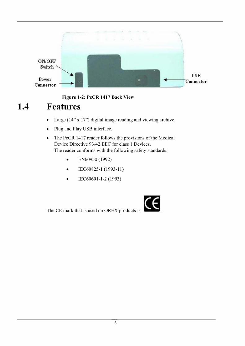
Figure 1-2: PcCR 1417 Back View
1.4 Features • Large (14” x 17”) digital image reading and viewing archive.
• Plug and Play USB interface.
• The PcCR 1417 reader follows the provisions of the Medical Device Directive 93/42 EEC for class 1 Devices. The reader conforms with the following safety standards:
• EN60950 (1992)
• IEC60825-1 (1993-11)
• IEC60601-1-2 (1993)
The CE mark that is used on OREX products is .
3
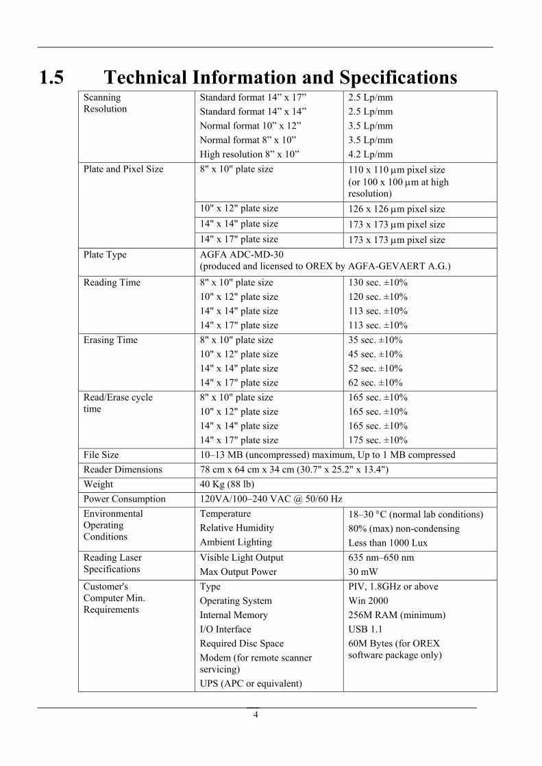
1.5 Technical Information and Specifications Scanning Resolution
Standard format 14” x 17” Standard format 14” x 14” Normal format 10” x 12” Normal format 8” x 10” High resolution 8” x 10”
2.5 Lp/mm 2.5 Lp/mm 3.5 Lp/mm 3.5 Lp/mm 4.2 Lp/mm
8" x 10" plate size 110 x 110 µm pixel size (or 100 x 100 µm at high resolution)
10" x 12" plate size 126 x 126 µm pixel size 14" x 14" plate size 173 x 173 µm pixel size
Plate and Pixel Size
14" x 17" plate size 173 x 173 µm pixel size Plate Type AGFA ADC-MD-30
(produced and licensed to OREX by AGFA-GEVAERT A.G.) Reading Time 8" x 10" plate size
10" x 12" plate size 14" x 14" plate size 14" x 17" plate size
130 sec. ±10% 120 sec. ±10% 113 sec. ±10% 113 sec. ±10%
Erasing Time 8" x 10" plate size 10" x 12" plate size 14" x 14" plate size 14" x 17" plate size
35 sec. ±10% 45 sec. ±10% 52 sec. ±10% 62 sec. ±10%
Read/Erase cycle time
8" x 10" plate size 10" x 12" plate size 14" x 14" plate size 14" x 17" plate size
165 sec. ±10% 165 sec. ±10% 165 sec. ±10% 175 sec. ±10%
File Size 10–13 MB (uncompressed) maximum, Up to 1 MB compressed Reader Dimensions 78 cm x 64 cm x 34 cm (30.7" x 25.2" x 13.4") Weight 40 Kg (88 lb) Power Consumption 120VA/100–240 VAC @ 50/60 Hz Environmental Operating Conditions
Temperature Relative Humidity Ambient Lighting
18–30 °C (normal lab conditions) 80% (max) non-condensing Less than 1000 Lux
Reading Laser Specifications
Visible Light Output Max Output Power
635 nm–650 nm 30 mW
Customer's Computer Min. Requirements
Type Operating System Internal Memory I/O Interface Required Disc Space Modem (for remote scanner servicing) UPS (APC or equivalent)
PIV, 1.8GHz or above Win 2000 256M RAM (minimum) USB 1.1 60M Bytes (for OREX software package only)
4

2. Using the PcCR 1417 System
2.1 Overview
2.2
This section provides a general flowchart and step-by-step instructions on how to scan a plate using the PcCR 1417 System, and instructions on how to change the photo multiplier (PM) gain value of a poor or over exposed image.
Language Support The PcCR 1417 system supports interface in different languages.
NOTE: To enable language support, ensure that your computer runs on a Windows 2000, system (English version).
To change the interface language
1. From the Desktop go to Settings Control Panel; then double-click the Regional Settings icon.
2. From the Change Locale pull-down menu, choose the required language; for example, Chinese (PRC).
3. Click Set as default; then select the same language again; for example, Chinese (PRC).
4. At the prompt, select Yes.
5. Check that the chosen language support is installed on
your computer. 6. Click OK to reboot the computer.
5

7. The computer restarts, running all applications, including the PcCR 1417, with the selected language.
8. If the language used is Chinese, enter the Scanner Interface – the Advanced tab.
9. From the Language drop-down menu, select Chinese RPS.
6
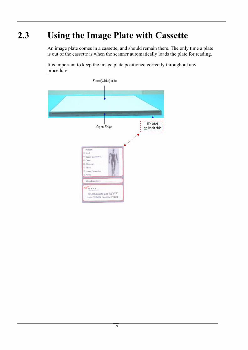
2.3 Using the Image Plate with Cassette An image plate comes in a cassette, and should remain there. The only time a plate is out of the cassette is when the scanner automatically loads the plate for reading.
It is important to keep the image plate positioned correctly throughout any procedure.
7

To load a cassette into the reader:
1. Verify that the scanner is On, and that the System LED is green, indicating that the scanner is ready.
2. Insert the cassette into the scanner:
• The face (white) side faces up,
• The open edge points toward the scanner, and
• The cassette is centered exactly from side to side in the scanner slot.
The cassette locks when it reaches its proper position in the scanner. Once the cassette locks, the image plate loads automatically.
Ordinarily, the cassette unlocks automatically after scanning, ready for re-use. In case you need to unlock the cassette manually, pull the screw beneath the slot to unlock the cassette.
8
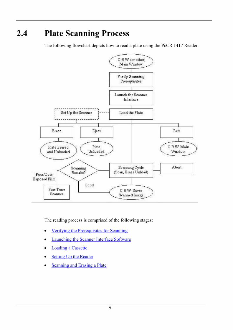
2.4 Plate Scanning Process The following flowchart depicts how to read a plate using the PcCR 1417 Reader.
The reading process is comprised of the following stages:
• Verifying the Prerequisites for Scanning
• Launching the Scanner Interface Software
• Loading a Cassette
• Setting Up the Reader
• Scanning and Erasing a Plate
9
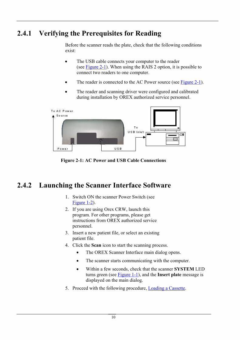
2.4.1 Verifying the Prerequisites for Reading Before the scanner reads the plate, check that the following conditions exist:
• The USB cable connects your computer to the reader (see Figure 2-1). When using the RAIS 2 option, it is possible to connect two readers to one computer.
• The reader is connected to the AC Power source (see Figure 2-1).
• The reader and scanning driver were configured and calibrated during installation by OREX authorized service personnel.
Figure 2-1: AC Power and USB Cable Connections
2.4.2 Launching the Scanner Interface Software 1. Switch ON the scanner Power Switch (see
Figure 1-2). 2. If you are using Orex CRW, launch this
program. For other programs, please get instructions from OREX authorized service personnel.
3. Insert a new patient file, or select an existing patient file.
4. Click the Scan icon to start the scanning process. • The OREX Scanner Interface main dialog opens.
• The scanner starts communicating with the computer.
• Within a few seconds, check that the scanner SYSTEM LED turns green (see Figure 1-1), and the Insert plate message is displayed on the main dialog.
5. Proceed with the following procedure, Loading a Cassette.
10

2.4.3 Loading a Cassette
Figure 2-2: Loading the Cassette
1. Place and center the cassette on the Cassette Tray (10" or 14" cassette width, shown in Figure 1-1).
2. Slightly push the cassette into the scanner (Figure 2-2) until it clicks into the locked position, and the PROCESS LED turns orange and starts blinking.
• The plate is automatically "pulled" and loaded into the scanner.
• The PROCESS indication LED changes from orange to green.
• In the Scanner Interface’s main dialog, the Scan, Erase, Exit, Setup and Eject functions turn valid.
The reader is now in the correct condition to scan the loaded plate. The Plate “inch” x “inch” is ready... message is displayed on the main dialog.
At this point, you can choose to perform any of the following actions:
• Unload the plate by clicking Eject.
• Erase the loaded plate by clicking Erase.
• Cancel and close the Scanner Interface by clicking Exit.
• Scan the loaded plate. Proceed with the following procedure, Setting Up the Scanner.
If no scanning is performed within 2 minutes, the cassette is ejected automatically.
11

2.4.4 Setting Up the Scanner 1. Click the Setup button in the scanner interface. The Setup dialog box
opens. In the Setup dialog box, select the Configuration tab. 2. To set the size of the area to be scanned, left click the Plate “inch” x
“inch” is ready… message. A drop-down-list appears. From the drop-down list, select the desired holder size. A 14” x 17” holder can be read partially by selecting a smaller holder size.
3. Select an Organ and a Sub-Organ by clicking the image of the body on the left side of the main dialog.
a. Point your cursor at one of the body organs on the image. A popup menu opens.
b. From the popup menu, select the sub-organ you want to scan.
4. Proceed with the following procedure, Scanning and Erasing a Plate.
12
2.4.5 Scanning and Erasing a Plate
IMPORTANT
While scanning, do not perform any other operation on your computer (for example, printing, network operation, or emailing). These operations may result in errors in the scanning process.
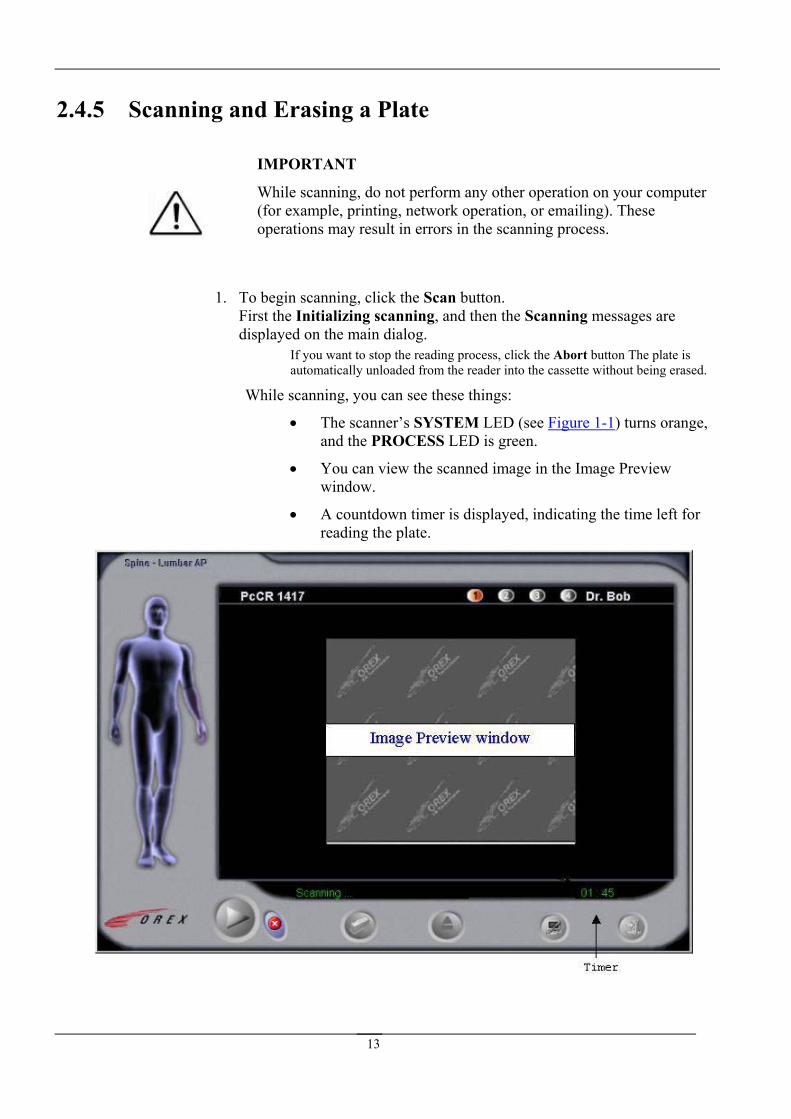
1. To begin scanning, click the Scan button. First the Initializing scanning, and then the Scanning messages are displayed on the main dialog.
If you want to stop the reading process, click the Abort button The plate is automatically unloaded from the reader into the cassette without being erased.
While scanning, you can see these things:
• The scanner’s SYSTEM LED (see Figure 1-1) turns orange, and the PROCESS LED is green.
• You can view the scanned image in the Image Preview window.
• A countdown timer is displayed, indicating the time left for reading the plate.
13

When the scanner has finished reading the plate, the digital image appears on the viewer.
• If Auto erase has been set in advance, an Erase message appears after scanning is completed. To view the Erase message, you must re-activate the Scanner Interface.
• If Auto erase hasn’t been set in advance, insert the film, and wait for system initialization to be completed. When the Plate “width” x “length” is ready... message is displayed on the main dialog, press the Erase button. A countdown timer is displayed only in the non-automatic erasing mode.
2. Save the scanned image in the patient folder.
You have completed the plate scanning process. At this point you can re-use the scanned and erased plate.
14
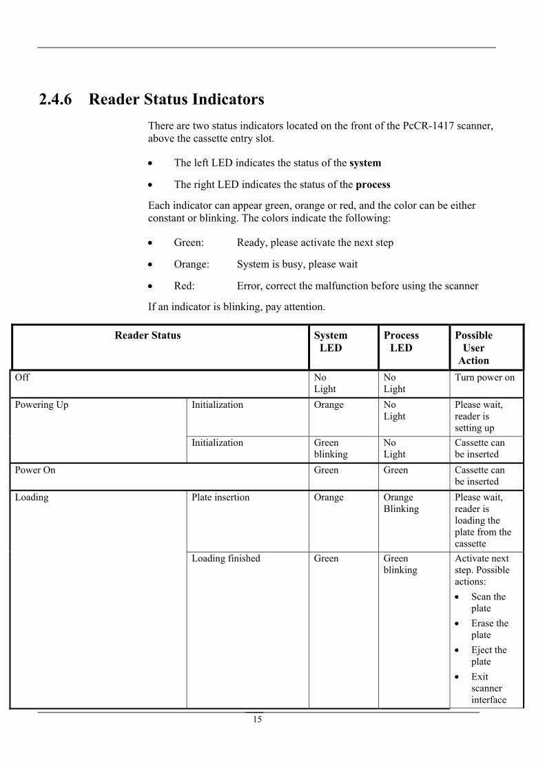
2.4.6 Reader Status Indicators There are two status indicators located on the front of the PcCR-1417 scanner, above the cassette entry slot.
• The left LED indicates the status of the system
• The right LED indicates the status of the process
Each indicator can appear green, orange or red, and the color can be either constant or blinking. The colors indicate the following:
• Green: Ready, please activate the next step
• Orange: System is busy, please wait
• Red: Error, correct the malfunction before using the scanner
If an indicator is blinking, pay attention.
Reader Status m D L
Possible User
Action
SysteLE
Process ED
No Light
Tu
lization Oran No PleasLight reade
settinlization Gree
blinkNo Light
Casbe i
Green Green
Orange Blinking
loading the
blinking steact•
•
Ep
Off No Light
rn power on
Powering Up Initia ge e wait, r is g up
Initia n ing
sette can nserted
Power On Cassette can be inserted
Loading Plate insertion Orange Please wait, reader is
plate from the cassette
Loading finished Green Green Activate next p. Possible ions: Scan the plate Erase the plate
• ject the late
• Exit scanner interface
15
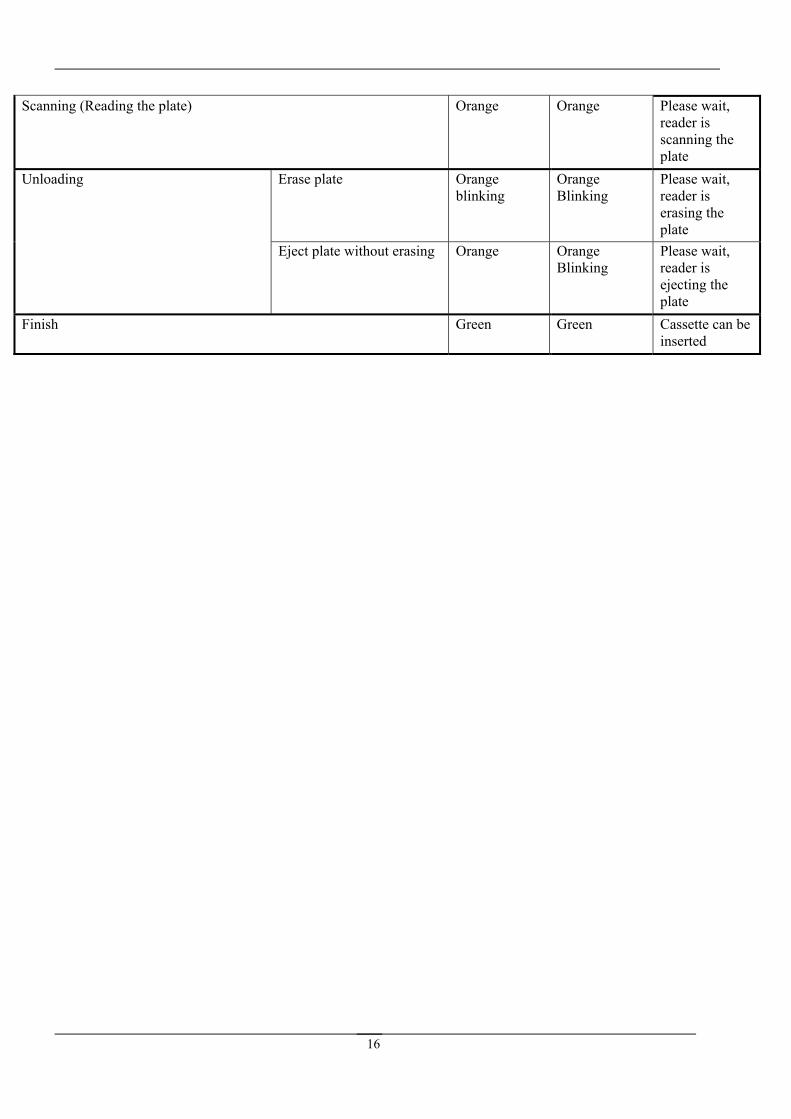
Scanning (Reading th e Orange Please wait, reader is scanning the plate
e plate) Orang
Unloading Please wait, reader is erasing the plate
Erase plate Orange blinking
Orange Blinking
Orange Blinking
Please wait, reader is ejecting the plate
Eject plate without erasing Orange
Finish Green Green Cassette can be inserted
16
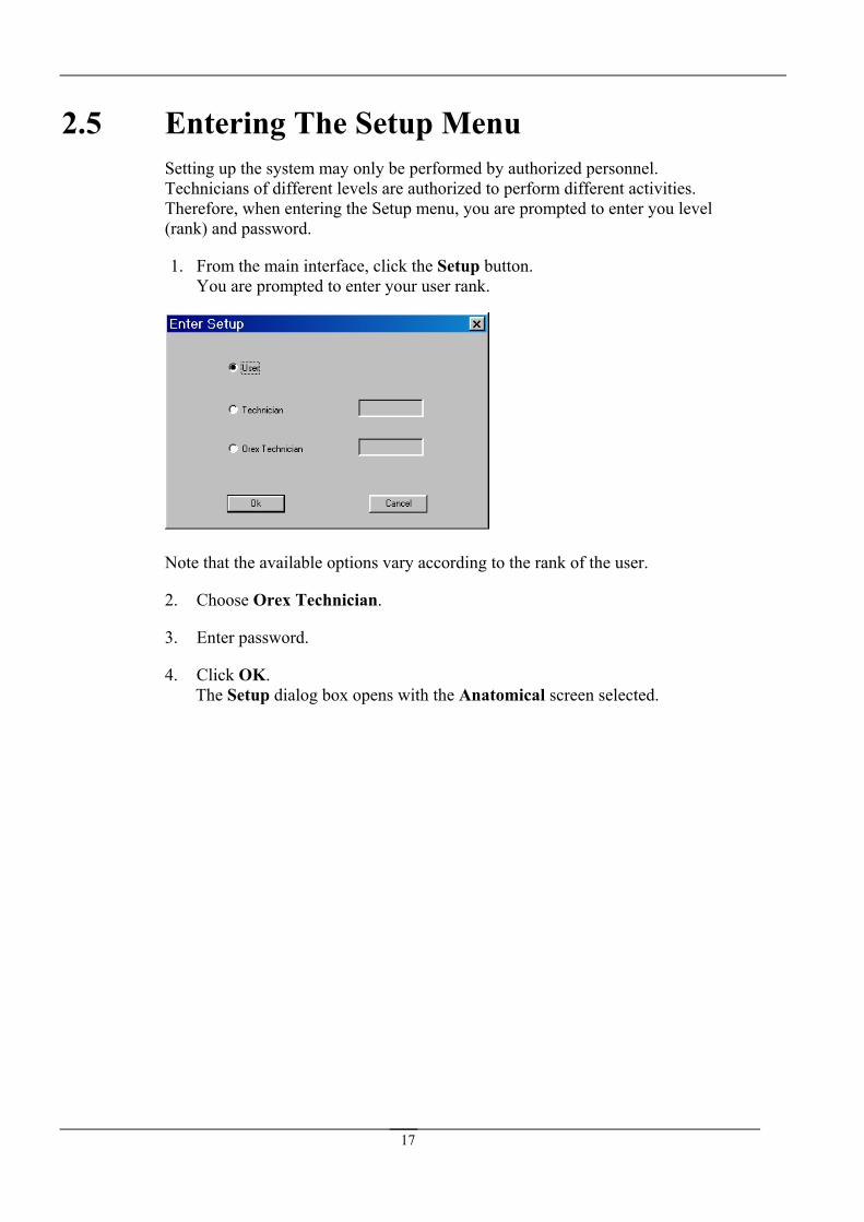
2.5
rd.
1. From the main interface, click the Setup button. You are pro ur user rank.
Entering The Setup Menu Setting up the system may only be performed by authorized personnel. Technicians of different levels are authorized to perform different activities. Therefore, when entering the Setup menu, you are prompted to enter you level (rank) and passwo
mpted to enter yo
Note that the available options vary according to the rank of the user.
2. Choose Orex Technician.
3. Enter password.
4. Click OK. The Setup dialog box opens with the Anatomical screen selected.
17

2.6 CIn some c s, gain of the sub- ged, the new optical gain setting will affect the results of scanned images in the relevant unit only
hanging a PM Gain Value ase it is possible to control the scanning results by changing the optical
organ image. Once chan when that same sub-
organ is s cte
ele d.
IMPORTANT
The Offset parameter is set during installation and calibratio
n of your PcCR 1417 System (refer to section 3). Do not change this value!
o change a PM gain value:
1. From the main interface, click the Setup button. The Setup dialog box opens with the Anatomical screen selected.
T
2. From the Organ drop-down list, select an organ (unless an organ has already been selected in the main dialog).
3. From the Sub Organ drop-down list, select the sub-organ image for which you would like to change the PM Gain (unless the sub-organ has already been selected in the main dialog).
18

4. Change/adjust the Sub-Organ PM Gain (in the Sub organ acquisition setsection):
up
b
(in case of over exposure), decrease the Sub Organ PM Gain by 10.
5. Click OK to return to the Scanner Interface’s main dialog.
6. R rm provided in section 10
• To get a darker image (in case of poor exposure), increase the SuOrgan PM Gain by 10.
• To get a lighter image
ecord any PM gain changes you make (fo ).
You have completed changing a PM gain value.
19
2.7 Adju inThe Scanner Interface is designed to work with up to four x-ray machines. Each machine is represented by a number, and includes a unique set of PM Gain, offset, and filtration ues oing to use by clicki
To adjust the system to an x-ray unit:
1. so be done on the Anatomical tab of the Setup dialog.
2. Once inside a specific unit, you can use the Image Filtering and Window Leveling
Filtering Notes:
ox under OREX Filters Setup (technician password required), the Scanner Interface processes the image using the
screen (and that are specific to every sub-organ in each unit).
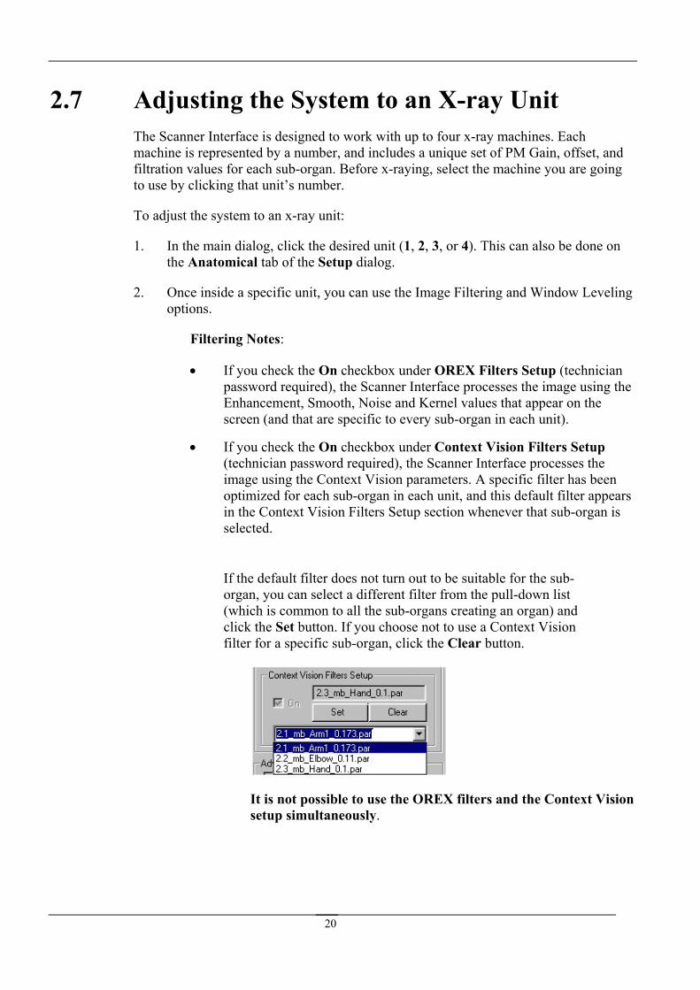
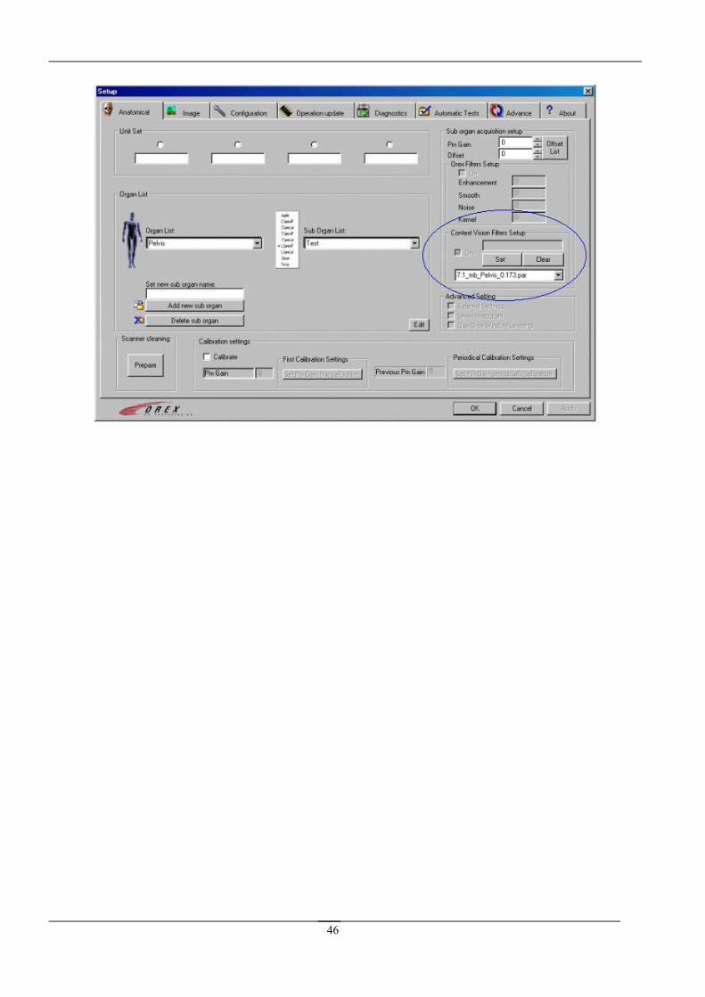
• If you check the On checkbox under Context Vision Filters Setup the
image using the Context Vision parameters. A specific filter has been optimized for each sub-organ in each unit, and this default filter appears in the Context Vision Filters Setup section whenever that sub-organ is selected.
If the default filter does not turn out to be suitable for the sub-organ, you can select a different filter from the pull-down list (which is common to all the sub-organs creating an organ) and click the Set button. If you choose not to use a Context Vision filter for a specific sub-organ, click the Clear button.
st g the System to an X-ray Unit
val for each sub-organ. Before x-raying, select the machine you are gng that unit’s number.
In the main dialog, click the desired unit (1, 2, 3, or 4). This can al
options.
• If you check the On checkb
Enhancement, Smooth, Noise and Kernel values that appear on the
(technician password required), the Scanner Interface processes
It is not possible to use the OREX filters and the Context Vision setup simultaneously.
20
• If you check the Use OREX Window Leveling checkbox (technicipassword required), the Scanner Interface searches for optimal wind
an ow
leveling values (for Width and Center parameters) to be used by the local viewer.
king the External Settings checkbox (technician password required) allows an external program to select the organ, sub-organ and
n the Anatomical tab. After you name a unit, that name appears on the main dialog whenever that unit is activated.
2.8 o ad t the relevant organ, insert the new sub-organ,
and click the Add .
gan button.
Note:
cally saved in all units.
• Chec
resolution.
3. Each unit can be given a name o
Adding and Deleting Sub-organs If you want t d a new sub-organ, selec
new sub-organ button
If you want to delete a sub-organ, select it and click the Delete sub-or
When you add/delete sub-organs, changes are automati
21

3. X-ray M c
3.2 Calibrat3.2.1 Offset C
1. Put the 14” x 17” cassette containing the phosphor plate into the scan
2. Veri
3. Erase the phosphor plate twice (to eliminate any remainder of information on the film).
4. In the main interface, click the Setup button. The Setup dialog opens.
5. From the Setup dialog, select the Image tab. In the Data correction method field, select No Correction. Then Save.
a hine-to-Scanner Calibration
3.1 Overview This section provides step-by-step instructions on how to calibrate the reader to the local x-ray machine. Calibration is unit-specific (results are saved only in the unit that is active while calibrating).
The calibration procedure results in setting default values for offset and PM gain for all the organs and sub-organs specific to the scanner and x-ray machine.
Objective: The objective is to create a look-up table (LUT) containing offset and PM gain values for all organs.
Frequency: Set calibration initially Calibrate periodically
Responsibility: Initial calibration: technician/distributor Periodic calibration: scanner owner/operator
Required Tools and Equipment: ● 14” x 17” blank phosphor plate ● Dosimeter
ion Procedure alibration
ner.
fy that the system is closed (to eliminate light penetration).
22

6. On the main screen of the scanner interface, click the Plate size field. From the pop-up menu that opens, select the Offset calibration function.
7. Click the Start scan button. For every PM gain, the system calculates an equivalent offset value.
The sySucces
stem finishes the first part of calibration by displaying either the sful or Failure message box.
We estimate that an empty plate=no radiation=minimum information.
Note:
23
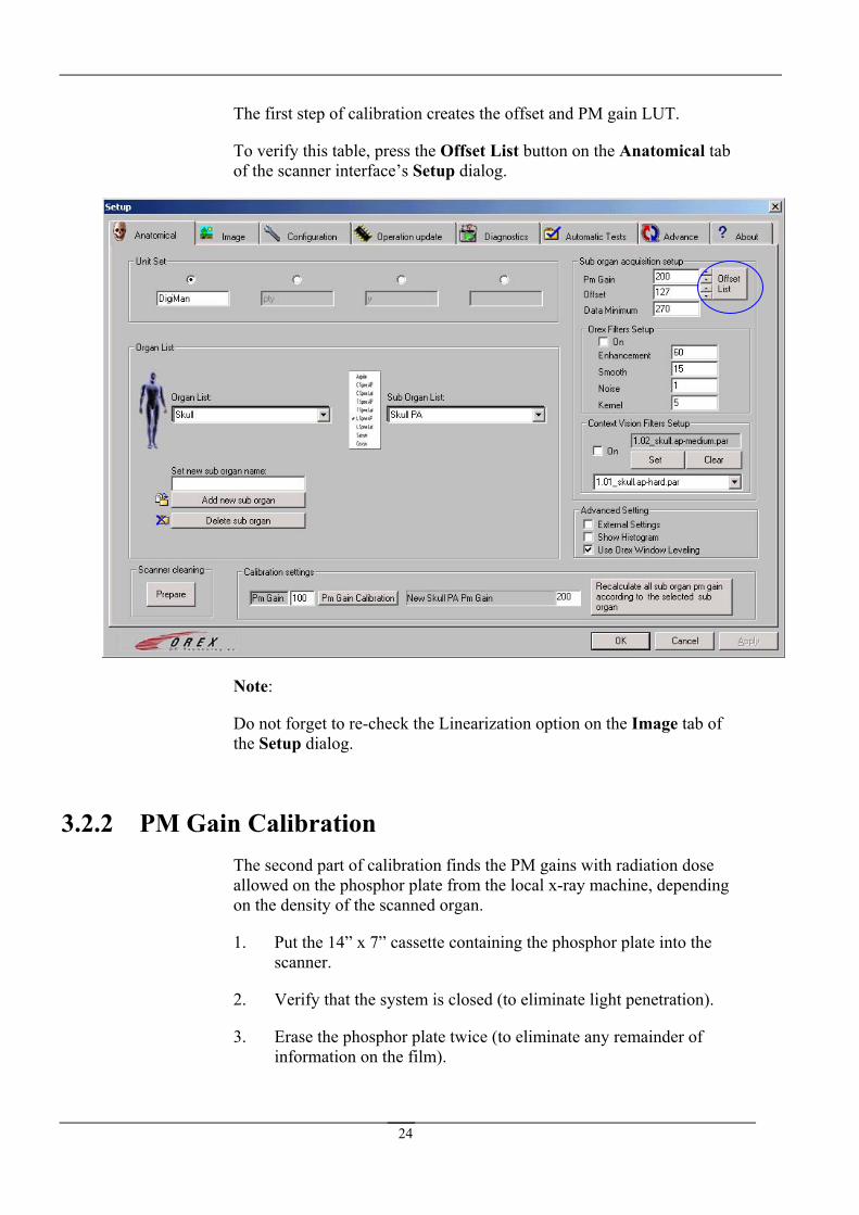
The first step of calibration creates the offset and PM gain LUT.
rify this table, press the Offset List button on the Anatomical tab scanner interface’s Setup dialog.
To veof the
Note:
tab of the
3.2.2 PM Gaingains with radiation dose
allowed on the phosphor plate from the local x-ray machine, depending
1. Put the 14” x 7” cassette containing the phosphor plate into the scanner.
2. Verify that the system is closed (to eliminate light penetration).
3. Erase the phosphor plate twice (to eliminate any remainder of information on the film).
Do not forget to re-check the Linearization option on the ImageSetup dialog.
Calibration The second part of calibration finds the PM
on the density of the scanned organ.
24

4. Expose the plate to x-ray. Use the maximum dose allowed depending on the local x-ray machine and the ‘film speed’ used. We estimate the parameters when using 400 ASA to be approximately 190 PM gain, and when using 200 ASA, to be approximately 150 PM gain.
5. On the main screen of the scanner interface, click the Plate sizeFrom the pop-up menu that opens, select the PM gain calibration function.
6. Click the Start scan button. The system calculates the PM gain. When the scanning finishes, this dialog box opens:
field.
7. Click Yes to save the news PM gain calibration value.
8. Open the Scanner Interface.
Select the Anatomical tab, ppassword.
th
9. ress Edit and insert the technician
10. Click e Set PM gain first calibration button. The following dialog box opens:
11. Click Yes to set the new calibrated value as the default.
If you are dissatisfied with the results, you can Fix the PM Gain for the specific organ you are calibrating, you can
12. Enter the new value required, in the New [organ] PM Gain.
25

e new value.
13. Click the Recalculate all sub-organ pm gain according to the selected sub-organ button. After you accept the warning message, the PM gain in all sub-organs allocated to the selected organ, are recalculated according to th
14. Close the Setup screen. The Scanner Interface’s main dialog re-opens.
15. Exit the Scanner Interface. The viewer program’s main window re-opens.
You have completed calibrating the scanner PM gain and Offset.
26

4. Image Property
4.1 Overview
4.2 Selecting an Image Path If an image fails to appear on your viewer, it is im ake sure that the image’s “Fixed image path” in your viewer m tches the location on your hard disk (contact OREX support for the location on the hard disk).
1. In the main dialog, click the Setup button. The Setup dialog opens. In the Setup
. From the Image format drop-down list, select an image format (bmp, raw data).
. From the Fixed Image path drop-down list, click the Browse button, and browse to the correct location. The Fixed Image path is automatically updated.
The Image Property section on the Image tab allows you to choose:
• an image format.
• a path to the image’s location on your hard disk, from which the viewer reads the raw image file.
portant to ma
dialog, select the Image tab.
2
3
27

5. Resolution, Orientation and Linearization
5.1 Overview The 8” x 10” holder can be scanned in either normal or high resolution. Reading a plate in high resolution is recommended whenever you wish to focus on small structures (physiological or pathological).
The Scanner Interface creates a mirror image from input, so that left and right appear as they do on regular x-ray film:
Linearization is a mathematical algorithm that corrects distortions in the plate’s absorption. Using this algorithm promotes a more reliable image.
5.2 Setting Resolution, Orientation and Linea
1. In the main dialog, click the Setup button. The Setup dialog opens. In the Setup
2. On the Image tab, in the small plate resolution section, if you check the Always s
rization
dialog, select the Image tab.
Ask check box, the following dialog box will open each time an 8” x 10” holder iloaded into the scanner:
solution of your choice, and click OK.
3. If you do not want this dialog box to appear prior to every small plate scanning procedure, make sure the Always Ask check box is not checked on the Image tab.
In the 8” x 10” Plate dialog box, check the re
28

4. To select permanent normal resolution, do not check the Normal Resolution check box. Leave the Normal Resolution check box empty.
5. To select permanent high resolution, check the Normal Resolution check box, and the Normal Resolution text immediately changes to High Resolution. The end
check box is checked. result is the High Resolution A Film “8” x “10” HRwhenever high resolution is selected.
If you wish that the systemimage, select the Auto Shutter
If you wish to change imboxes: Horizontal Flip or
is ready... message is displayed on the main dialog
6. automatically erase any white outline around the checkbox.
7. age orientation, check one of the Rotate Canvas check Vertical Flip.
8. If you want to use the linearization algorithm, select Linearization from the Data correction method drop-down list. If you do not wish to use this algorithm, select No Correction.
Note:
ou want them to be saved, except for changes in the Image Property section. You must save all the changes you make on the Image tab if y
29

6. Era
6.1 Overview The scanner Configuration library consists of several options that are used daily:
• Note that ACL 4 Nominal at the bottom of the screen is selected.
• A automatically after the scan is completed.
• Erase factor enables you to choose the number of erasing steps, which is propo na ble range is 8-127.
• Autom tic a scanning procedure as soon as the cassette enters the scanner.
sing Options and Automatic Scan
uto erase after scan enables the erasing of a plate
rtio l to erasing time. The availa
a scan enables the initiation of
Note:
Remember to click Reset Lamp Error after you repair an erase lamp problem. Failure to do so will result in illogical Lamp error messages.
30

6.2 Setting Erasing Options and Auto Scan 1. In the main dialog, click the Setup button. The Setup dialog opens. In the Setup
y.
ve. Scanning will occur
dialog, select the Configuration tab.
2. Check the Auto erase after scan checkbox, then click Save.
3. Perform a scan. After scanning is completed, erasing occurs automaticall
4. Check the Auto Scan checkbox, then click Saautomatically as soon as film enters the scanner.
5. For optimal erasing, enter the following Erase factors, and Save:
• Agfa/Fuji 8 x 10 film: 38
• Agfa/Fuji 14 x 17 film: 38
31

7.
exposure is immediately fed into the locally positioned CR (Computed Radiography) a
nce power by up to two. In addition lexibility and
plete the scanners iltering
RAIS 2 When performing an x-raying session, x-ray images are taken sequentially, one at a time, by altering the position of the patient. These images, displaying an organ from different angles, are grouped together to create a patient study. With the OREX concept, each x-ray
system. As the CR scanner can only scan images one by one, the duration of creating study is limited by the throughput of this local CR system.
In the RAIS 2 system, the task of creating a study from the x-ray exposures is shared by two independent CR scanners, thus raising the performato the reduction of the study-creating duration, the RAIS 2 system offers freliability (redundancy), inherent to the fact the each CR scanner operates as a comsystem with the capability of solely performing the scanning task. If one offails, this does not affect the operation of the other one. The scanning and ffunctions are synchronized between the units; it is not possible to scan on one unit, while filtering on the other.
A special GUI enables viewing the control panels of both devices connected to one computer. Each control panel enables direct communication with the specific independent device for set-up, control and diagnostics.
32
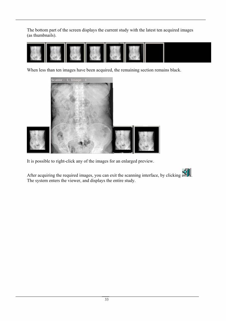
The bottom part of the screen displays the current study with the latest ten acquired im(as thumbnails).
ages
When less than ten images have been acquired, the remaining section remains black.
It is possible to right-click any of the images for an enlarged preview.
After acquiring the required images, you can exit the scanning interface, by clicking . The system enters the viewer, and displays the entire study.
33

34
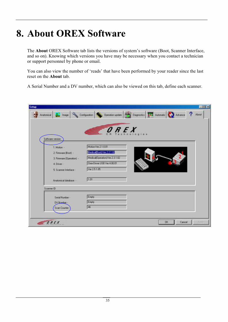
8. About OREX Software The Abo ab lists the versions of system’s software (Boot, Scanner Interface, and so on). Knowing which versions you have may be necessary when you contact a technician or support personnel by phone or email.
You can e last reset on tab.
A Serial ber, which can also be viewed on this tab, define each scanner.
ut OREX Software t
also view the number of ‘reads’ that have been performed by your reader since ththe About
Number and a DV num
35

9. Troubleshooting
9.1 Overview This section provides general guidelines for correcting malfunctions that may occur when using the PcCR 1417 System, and answers to Frequently Asked Questions (FAQs)
9.2 Error IMPORTANT
Inform OREX directly or through your vendor about any error messages that may appear. Do not attem t to repair the malfunction by yourself!
Error Message Cause/Description
.
List
p
Update software please Memory of Operation Firmware is empty.
Wrong loader parameters Number of steps for loader’s film entering/exiting is not correct.
Lamp 1 turn on fail First erase lamp cannot turn on—erasing procedure will be performed at half speed.
Lamp 2 turn on fail Second erase lamp cannot turn on—erasing procedure will be performed at half speed.
Both erase lamps are not working. Erase cannot be performed.
Erasing procedure cannot be performed. If detected in the middle of a scan, the scan will be completed, but the cassette will be ejected without being erased.
Carrier return fail Stepper motor malfunction.
W0 sensor ON state fail W0 sensor continuously recognizes film passing through it.
Roller sensor ON state fail Scanner continuously recognizes film inside rollers.
W0 sensor OFF state fail W0 sensor cannot recognize film passing through it.
Roller sensor OFF state fail Scanner cannot recognize film inside rollers.
Z0 sensor ON state fail Z0 sensor continuously recognizes film passing through it.
Cassette insert fail * Cassette lock mechanism has failed.
Plate unload fail * Cassette release mechanism has failed.
* In case of Cassette insert/Plate unload fail message, pull the handle under the cassette tray.
36
9.3 Frequently Asked Questions
Question:
Answer:
Question:
Answer:
Question:
Answer:
Question:
Answer:
37
10. Recording Sub-Organ Offset and PM Gain Values
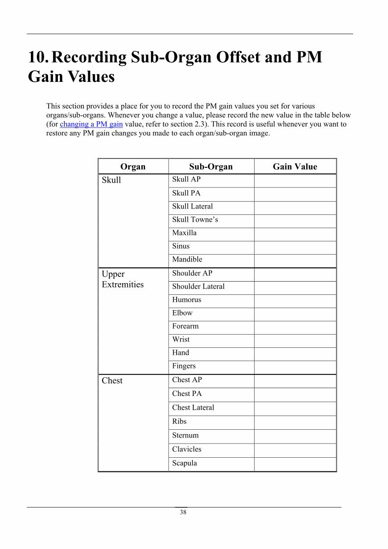
This section provides a place for you to record the PM gain values you set for various organs/sub-organs. Whenever you change a value, please record the new value in the table below (for changing a PM gain value, refer to s record useful whenever you want to restore any PM gain changes you made to each organ/sub-organ image.
Organ Sub-Organ Gain Value
section 2.3). Thi is
Skull AP
Skull PA
Skull Lateral
Skull Towne’s
Maxilla
Sinus
Skull
Mandible
Shoulder AP
Shoulder Lateral
Humorus
Elbow
Chest AP
Chest PA
Chest Lateral
Ribs
Sternum
Clavi
Scapul
Forearm
Wrist
Hand
Upper Extremities
Fingers
cles
Chest
a
38
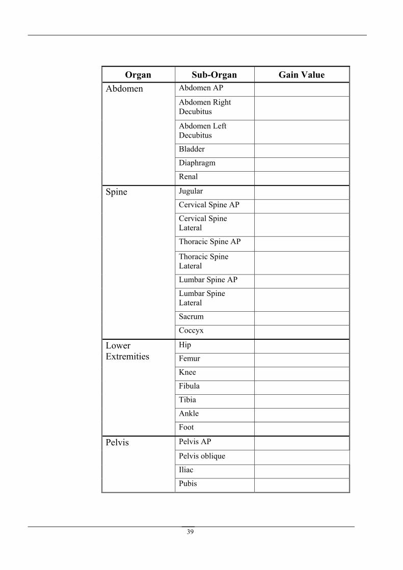
Organ Sub-Organ Gain Value Abdomen AP
Abdomen Right Abdomen
Decubitus
Abdomen Left Decubitus
Bladder
Diaphragm
Renal
Jugular
Cervical Spine AP
Cervical Spine
Spine
Lateral
Thoracic Spine AP
Thoracic Spine Lateral
Lumbar Spine AP
Lumbar Spine Lateral
Sacrum
Coccy
x
Hip Lower Femur
Knee
Extremities
Fibula
Tibia
Ankle
Foot
Pelvis AP
Pelvis oblique
Iliac
Pelvis
Pubis
39
11. Cle n
11.1 Overview The rollers should be cleaned periodically to rem all particles. The
age plate from the cassette into the reader.
The Cleaning device includes the following item
C
• envelope.
11.2 1. Remove the cassette and plates form
3. On the Scanner Interface, click the Setup button. The Setup dialog box opens.
4. In the Setup
5. Click the Prepare box located in the lower left corner of the Anatomical
6. Disconnect the reader from
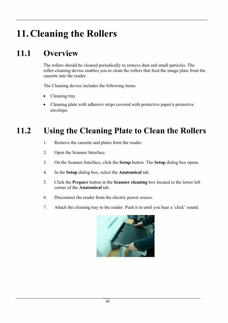
7.
a ing the Rollers
ove dust and smroller-cleaning device enables you to clean the rollers that feed the im
s:
• leaning tray
Cleaning plate with adhesive strips covered with protective paper/a protective
Using the Cleaning Plate to Clean the Rollers the reader.
2. Open the Scanner Interface.
dialog box, select the Anatomical tab.
button in the Scanner cleaning tab.
the electric power source.
Attach the cleaning tray to the reader. Push it in until you hear a ‘click’ sound.
40

8. Remove the transparent protective sheet/protective envelope from the cleaning plate.
ove the protective paper strips from9. Rem the cleaning plate to expose the adhesive.
10. Place the cleaning plate on the tray. Make sure the cleaning plate is placed in the correct direction, as specified on the plate.
11. While holding onto the plate, push the plate into the reader. It should go in almost entirely. A 10 cm segment of the plate should remain visible. Then pull the plate out.
12. Repeat step 11 four to six times.
41
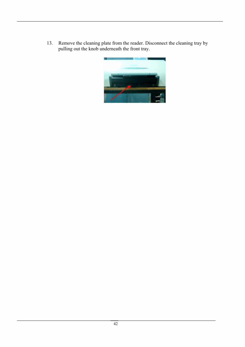
13. Remove the cleaning plate from the reader. Disconnect the cleaning tray by pulling out the knob underneath the front tray.
42
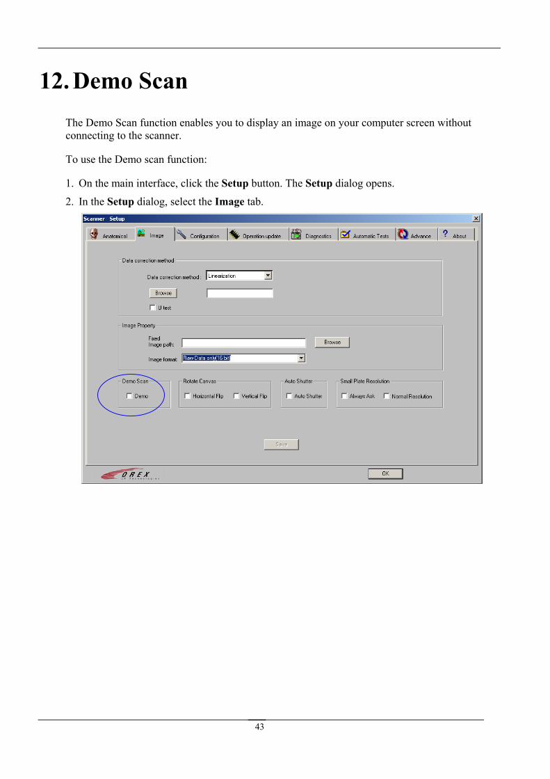
12. Demo Scan function enables you to display an image on your computer screen without The Demo Scan
connecting to the scanner.
To use the Demo scan function:
1. On the main interface, click the Setup button. The Setup dialog opens.
2. In the Setup dialog, select the Image tab.
43
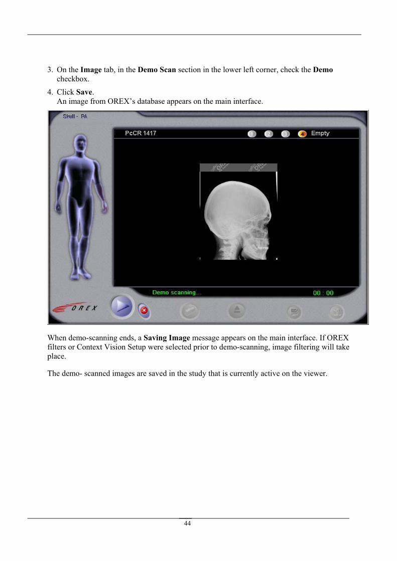
3. On the Image tab, in the Demo Scan section in the lower left corner, check the Demo checkbox.
4pears on the main interface.
. Click Save. An image from OREX’s database ap
en demo Saving Image message appears on the main interface. If OREX
Whfplace.
-scanning ends, a ilters or Context Vision Setup were selected prior to demo-scanning, image filtering will take
The demo- scanned images are saved in the study that is currently active on the viewer.
44
45
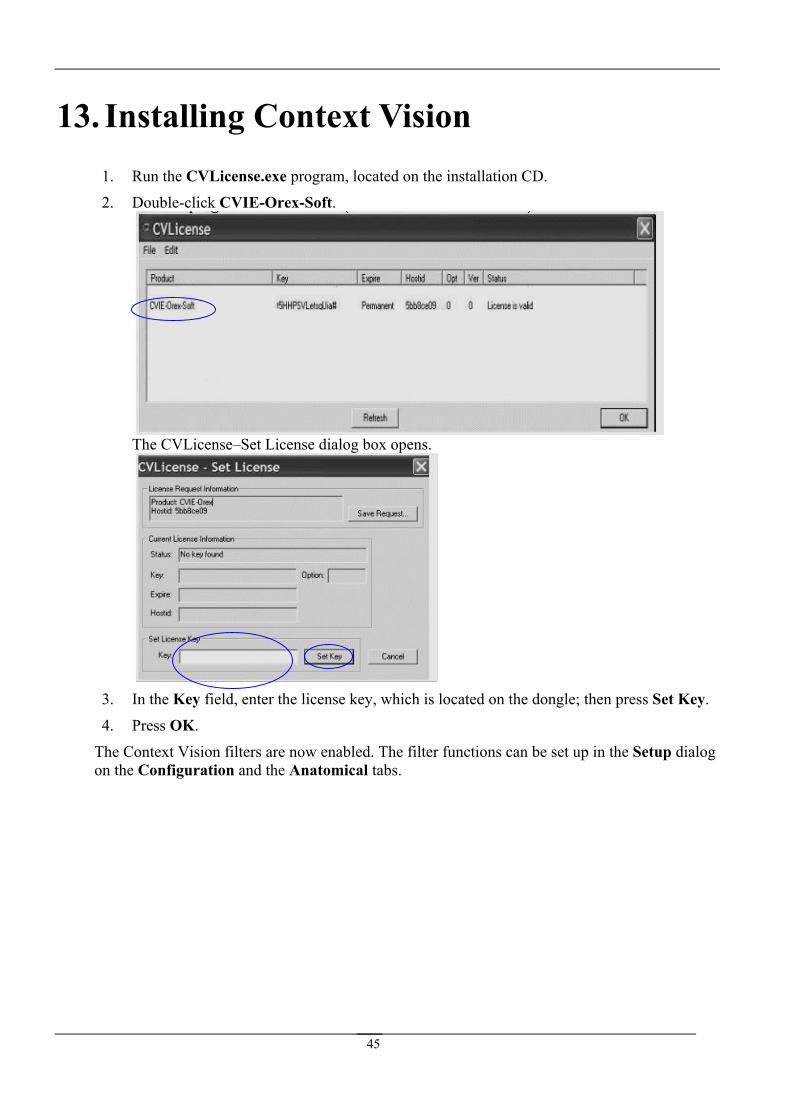
13. Installing Context Vision 1. Run the CVLicense.exe program, located on the installation CD.
2. Double-click CVIE-Orex-Soft.
The CVLicense–Set License dialog box opens.
3. In the Key field, enter the license key, which is located on the dongle; then press Set Key.
4. Press OK.
The Context Vision filters are now enabled. The filter functions can be set up in the Setup dialog on the Configuration and the Anatomical tabs.
46