pco electronic control chillers aries free …asami.lt/wp-content/uploads/ariesfc.pdf · pco...
TRANSCRIPT

p C O E l e c t r o n i c C o n t r o l
C H I L L E R SA R I E S F R E E - C O O L I N G
ELECTRONIC CONTROL INSTRUCTION MANUAL
AS 201÷751 FC
Original instructions in Italian language SERVICE38178800849


ELECTRONIC CONTROL INSTRUCTION MANUALIndex
AS 201÷751 FC
1
EN
GL
ISH
EN
The data in this manual are not binding and may be changed by the manufacturer without notice. Reproduction of this manual, even partial, is strictly prohibited.
INDEXINDEX .................................................................................................................................................. 1
Chapter 1
TECHNICAL CHARACTERISTICS......................................................................................................... 41.1 Structure of units.............................................................................................. 41.2 Components of pCO network .......................................................................... 41.3 pCO inlet and outlet connections..................................................................... 41.4 Layout of module network............................................................................... 51.5 How to use the programmed Smart-Key ......................................................... 51.6 How to address pCO board .............................................................................. 61.7 Terminal unit.................................................................................................... 71.8 Hardware addressing of the local/remote terminal .......................................... 71.9 How to set the software address between the terminal and the board ............. 71.10 How to address the electronic thermostatic valves .......................................... 81.11 How to wire the terminal ................................................................................. 91.12 How to wire the remote terminal (optional) .................................................... 9
Chapter 2
PRESSURE AND TEMPERATURE TRANSDUCERS............................................................................... 112.1 Pressure transducers....................................................................................... 11
2.1.1 Inspection of the pressure transducer (only 4÷20mA) ................................... 112.2 Temperature probes ....................................................................................... 112.3 Function of transducers and of probes ........................................................... 122.4 Location of transducers.................................................................................. 12
Chapter 3
UTILISATION OF THE TERMINAL ..................................................................................................... 133.1 Display of pCO terminal................................................................................ 13
3.1.1 Displaying/signalling masks ........................................................................... 143.2 Terminal buttons ............................................................................................ 15
3.2.1 Function of combined buttons ........................................................................ 15Chapter 4
UNIT STARTING AND STOPPING ....................................................................................................... 164.1 Unit start-up ................................................................................................... 164.2 Automatic restart............................................................................................ 164.3 Unit switching off .......................................................................................... 16
Chapter 5
ACCESS TO THE PROGRAMMING ..................................................................................................... 175.1 How to modify a parameter in “Free Menu” ................................................. 175.2 How to modify a parameter of “Password Menu”......................................... 185.3 How to modify the language.......................................................................... 19
Chapter 6
MAIN SETTINGS ................................................................................................................................ 206.1 How to modify the setpoint value.................................................................. 206.2 How to modify the differential value............................................................. 216.3 How to modify the Free-Cooling Delta activation ........................................ 22
Chapter 7
TEMPERATURE REGULATION MANAGEMENT ................................................................................. 237.1 Water temperature regulation for conditioning use in chiller modality......... 23
7.1.1 NEUTRAL ZONE temperature regulation ..................................................... 237.2 Water temperature regulation in FREE-COOLING modus .......................... 257.3 Anti-freeze control ......................................................................................... 26

ELECTRONIC CONTROL INSTRUCTION MANUALIndex
AS 201÷751 FC
2
EN
GL
ISH
EN
The data in this manual are not binding and may be changed by the manufacturer without notice. Reproduction of this manual, even partial, is strictly prohibited.
Chapter 8
SETPOINT MANAGEMENT .................................................................................................................278.1 Fixed setpoint ................................................................................................. 278.2 Compensated setpoint ....................................................................................278.3 Double setpoint ..............................................................................................288.4 Adjustable setpoint by daily bands ................................................................28
Chapter 9
FREE-COOLING SYSTEM MANAGEMENT .........................................................................................299.1 Operating logic...............................................................................................299.2 Free-Cooling three-way-valve........................................................................30
Chapter 10
MANAGEMENT OF COMPRESSORS OPERATION ...............................................................................3210.1 Unit type and compressor number .................................................................3210.2 Working hours and startings of compressors and of the unit .........................3210.3 Compressors sequencing procedure ...............................................................33
10.3.1 Compressor sequencing procedure disabled ..................................................3310.3.2 Sequencing procedure “per compressor” ......................................................34
10.4 Compressors Pump-Down procedure (only AS 351÷751 FC units)..............3410.5 Compressors Unloading procedure ................................................................36
10.5.1 Unloading procedure by high pressure probes ..............................................37Chapter 11
FANS OPERATION MANAGEMENT.....................................................................................................3811.1 Condensing Fans ............................................................................................38
11.1.1 Management by step .......................................................................................3811.1.2 Management by variable speed ......................................................................3911.1.3 Management by variable speed on the medium value ....................................3911.1.4 Speed-Up time logic ........................................................................................40
11.2 Nightly operation ...........................................................................................4111.3 Free Cooling fans ...........................................................................................41
11.3.1 FC fans regulated by variable speed ..............................................................42Chapter 12
SINGLE OR DOUBLE PUMP OPERATION MANAGEMENT...................................................................4512.1 Operating hours and number of startings of the pump................................... 4512.2 Pump management and operation .................................................................. 45
12.2.1 Automatic rotation ..........................................................................................4612.2.2 Manual rotation ..............................................................................................46
Chapter 13
MANUAL PROCEDURE.......................................................................................................................47Chapter 14
ELECTRONIC THERMOSTATIC VALVE .............................................................................................4814.1 Operation........................................................................................................4814.2 Driver of the thermostatic valve.....................................................................48
Chapter 15
SUPERVISION SYSTEM.......................................................................................................................4915.1 Carel ............................................................................................................... 4915.2 Modbus...........................................................................................................4915.3 Gsm ................................................................................................................4915.4 Direct Modem (Rs232)................................................................................... 4915.5 LonWorks.......................................................................................................5015.6 Variables managed by the electronic control ................................................. 50
15.6.1 Digital variables .............................................................................................5015.6.2 Analogue variables ...................................................................... 5415.6.3 Entire variables ...............................................................................................56

ELECTRONIC CONTROL INSTRUCTION MANUALIndex
AS 201÷751 FC
3
EN
GL
ISH
EN
The data in this manual are not binding and may be changed by the manufacturer without notice. Reproduction of this manual, even partial, is strictly prohibited.
Chapter 16
MASKS NO PASSWORD REQUIRED.................................................................................................... 6016.1 Menu .............................................................................................................. 6016.2 Free Menu ...................................................................................................... 61
Chapter 17
MASKS REQUIRING A PASSWORD .................................................................................................... 6417.1 Menu with password ...................................................................................... 64
Chapter 18
ALARM MANAGEMENT ..................................................................................................................... 7918.1 Alarm signals ................................................................................................. 79
18.1.1 Alarm displaying ............................................................................................ 7918.2 Alarm resetting .............................................................................................. 7918.3 Alarms masks................................................................................................. 79
Chapter 19
HISTORY ........................................................................................................................................... 84Chapter 20
SETTING TABLES .............................................................................................................................. 8520.1 Settings without password ............................................................................. 8520.2 Settings with password .................................................................................. 86
Chapter 21
PARAMETERS WITH SETTINGS RELATED TO THE TYPE OF UNIT ................................................... 9021.1 Settings related to the alphanumeric string-code........................................... 9021.2 Settings related to the unit model .................................................................. 92

ELECTRONIC CONTROL INSTRUCTION MANUALTechnical characteristics
AS 201÷751 FC
4
EN
GL
ISH
EN
The data in this manual are not binding and may be changed by the manufacturer without notice. Reproduction of this manual, even partial, is strictly prohibited.
CHAPTER 1
TECHNICAL CHARACTERISTICS1 . 1 S t r u c t u r e o f u n i t s
All units have one circuit and are equipped with two SCROLL compressors.
These units are furnished with a pCO net.
1 . 2 C o m p o n e n t s o f p C O n e t w o r k
1 . 3 p C O i n l e t a n d o u t l e t c o n n e c t i o n sThe Fig.2 shows the planimetry of the pCO board.
Here are marked the connectors of all available inlets and outlets (J1÷J18).
Some inlets are used to receive signals of analogue type, others to receive signals of digital type.
The outlets are used to send signals of digital type.
Particulars of the board:
ATTENTIONThe planimetry which marks the utilisation of inlets and outlets of the board is shown in the wiring diagram annexed to each unit.
pCO network practically constitutes the unit electronic control and is
similar to a little hardware net (pLAN) formed of:
1. Terminal unit
2. Main control board
3. Telephone cable for connecting the terminal and the board
The Fig.1 shows the connections of the pLAN (Local Area Network)
which forms the classic hardware architecture of a pCO network with the
local/remote terminal (1).
Fig.1 COMPONENTS OF A PCO MODULE
Fig.2 BOARD OF PCO
1. Power supply connector 24 Vac
2. Telephone connector to terminal or to download/upgrade the
software using the Smart-Key.
3. RS485/Modem optoisolated board for serial line connection to
supervisory/telemaintenance systems (optional)
4. Collector for the connection of pCO boards to pLAN network
5. Outlet relay
6. Digital inlets;
Analogue inlets;
Analogue outlets.
2
13

ELECTRONIC CONTROL INSTRUCTION MANUALTechnical characteristics
AS 201÷751 FC
5
EN
GL
ISH
EN
The data in this manual are not binding and may be changed by the manufacturer without notice. Reproduction of this manual, even partial, is strictly prohibited.
1 . 4 L a y o u t o f m o d u l e n e t w o r kOn each unit is installed a board which, together with the terminal, constitutes pCO network.
The unit can operate in an independently way (LOCAL operation) or can operate connected to other units (until four units max., MODULAR operation).
ATTENTIONThe ARIES freecooling units can by utilized in the MODULAR operation.
In the event of modular operation, pCO hardware allows to manage a network of two until four modules.
Modular operation is used if you want to co-ordinate the operation of more machines.
The connected modules constitute the module network. It is important to define the module 1, that is the main module or Master module.
This is the module which co-ordinates the main functions of the unit group.
The other modules are defined secondary modules or Slave modules.
The definition of the modules is done software addressing the board.
The wiring diagram, annexed to the unit, explains the connection layout of the module network.
1 . 5 H o w t o u s e t h e p r o g r a m m e d S m a r t - K e yThe Smart-Key allows to download the programmes in pCO boards and to upload them from pCO boards.
LED of the Smart-Key:
ATTENTION
start + you record from the key to the pCO;
start + you record from the pcO to the key;
Each recording deletes the previous
Smart-Key buttons:The Key has two buttons which have the following functions:
• “mode” button is used to change from read to write modality.
(pCO write modality) (pCO read modality).
• “start” button allows to begin the read or write modality, that will be indicate by the relative symbols ( or ).
When the operation will be complete the buzzer will ring for 20 seconds.
If there is an error the symbol will switch on with the LED. The table below shows the cause of the problems:
LED on LED status Description
flashing The Key is connected to the pCO, during this phase, even some seconds, the start button is disabled.
start flashing The Key is checking the accesses
start + on pressing “start” button download the data into the pCO
start + on pressing “start” button the pCO begins to read the data in the pCO and download them in the key
start + on pressing “start” button you begins to read the alarm historic of the pCO
mode on pressed for 1 second you enter the write modality (IF ENABKLED)
Led on Led status Description
+ +flashing Communication error: no answer from the pCO or the firmware version of the key is not compatible
+ modeon Password error or the key is not compatible
+ modeflashing The key is not compatible

ELECTRONIC CONTROL INSTRUCTION MANUALTechnical characteristics
AS 201÷751 FC
6
EN
GL
ISH
EN
The data in this manual are not binding and may be changed by the manufacturer without notice. Reproduction of this manual, even partial, is strictly prohibited.
The following procedure describes what to do to download the program from the Smart-Key to the pCO card:
1. cut the power supply from the pCO turning off the machine main switch;
2. Disconnect the phone connector of the terminal from the pCO card.
3. Connect the key to the phone connector of the pCO as showed in the picture;.
4. Restore the power supply of the pCO card.
5. The symbols will light on and the buzzer will play.
6. Wait for some seconds till the key will become effective.
During this period the symbol will flash.
7. At the end the control will enter the program modality and the “start” button can be pressed to start the data transfer.
8. Before pressing the “start” button be sure that the symbol has been selected (pCO write mode). Otherwise press the “mode” button to start
the write modality; the symbol must be on (pCO write mode).
(pCO write mode)
(pCO read mode).
1 . 6 H o w t o a d d r e s s p C O b o a r dpCO controller needs to be addressed to operate in pLAN network.
The address modification is carried out using pGD terminal or a REMOTE terminal.
To modify the address by local/remote pGD terminal:
1. Switch off pCO;
2. Use a standard pGD terminal with the address as “0” (see paragraph 1.8 “Hardware addressing of the local/remote terminal” );
3. Disconnect pCO from eventual pLAN connections of other controllers (j11 terminal);
4. Switch on pCO pressing at the same time g and j buttons;
5. The following mask will appear after a few seconds:
+ start +
+buzzer
flashing and the buzzer is intemittent
The write command is failed
+ start +
+buzzer
flashing and the buzzer is intemittent
The read command is failed
+ start + +
buzzer
flashing and the buzzer is intemittent
The command to read the hysterics is failed.
+on The key has not one or more compulsory files.
+ +starton + start flashing The bios and the pCO hardware are not compatible
+ +modeon + mode flashing The software and the pCO hardware are not compatible
+ + on + flashing The historic configuration and the pCO hardware are not compatible.
+ on The memory is not enough to read the hysterics
+ +on Historical data not present in the pCO.
on The key is not programmed.
Led on Led status Description
PLAN ADRESS: 0
UP: INCREASE
DOWN: DECREASE
ENTER: SAVE & EXIT

ELECTRONIC CONTROL INSTRUCTION MANUALTechnical characteristics
AS 201÷751 FC
7
EN
GL
ISH
EN
The data in this manual are not binding and may be changed by the manufacturer without notice. Reproduction of this manual, even partial, is strictly prohibited.
6. To modify the address operate on g and f buttons, then press h button to confirm the new value.
1 . 7 T e r m i n a l u n i t
The unit has 6 buttons. Furthermore, the terminal is equipped with:
1. a LCD display for the displaying and programming;
2. LED indicators associated to buttons.
Furthermore, if requested each unit can be supplied with a REMOTE terminal for remote controlling and programming (see Fig.3).
1 . 8 H a r d w a r e a d d r e s s i n g o f t h e l o c a l / r e m o t e t e r m i n a lpGD remote terminal needs to be addressed to operate in pLAN network.
The address modification is possible only after switching off the terminal by the telephone connector, see chapter 1.2 “Components of pCO network” .
How to address pGD remote terminal:
ATTENTIONIf the event of MODULAR operation, fix the board address of each module as indicated below.
1 . 9 H o w t o s e t t h e s o f t w a r e a d d r e s s b e t w e e n t h e t e r m i n a l a n d t h e b o a r d
ATTENTIONBefore carrying out the following operations be sure that all the wiring of the board and of the terminal have been correctly carried out (seeparagraphs "1.2 Components of pCO network" and "1.3 pCO inlet and outlet connections").Be sure that all the indication about the hardware addressing have been followed (see paragraphs "1.6 How to address pCO board" and "1.8Hardware addressing of the local/remote terminal").
1. If the unit is off, switch it on operating on the breaker on the electrical panel, then wait for one minute at least to allow to pCO net to stabilize;
2. Assure that the unit is in STAND-BY;
A mask similar to the following one will appear;
The indication “Unit Off” must appear in the last row of the display:
3. At the same time keep pressed the buttons: g, f and h;
Each unit is furnished with a terminal for controlling the programming (see Fig.3).
The terminal unit, connected to the board of each module, is necessary to program
the unit and to display its working parameters.
It enables you to perform the following operations:
• programming via password;• programming without password;• display of all inlets/outlets;• possibility to modify run-time the operating setpoint value;• display of all measured values;• display of any alarm condition;• display of alarm historic.
Fig.3 PGD TERMINAL
1. at the same time press g, f, h buttons for 5 seconds,
2. the mask on the side will appear, the cursor will start to flash on the top left corner
3. To modify the remote terminal address, press h button; the cursor will move on address
field (nn)
4. Press g and f buttons to modify the address and h button to store the new value.
5. If the setting is different from the one stored before, the mask on the side will appear and the
new value will be stored in the permanent memory of the display.
12/11/02 03:00
Temp.IN : 000.0°C
Temp.OUT: 000.0°C
Unit Off
Display addresssetting.............................:nn
I/O Board address:xx
Display addresschanged

ELECTRONIC CONTROL INSTRUCTION MANUALTechnical characteristics
AS 201÷751 FC
8
EN
GL
ISH
EN
The data in this manual are not binding and may be changed by the manufacturer without notice. Reproduction of this manual, even partial, is strictly prohibited.
4. After a few seconds the following mask will appear;
Terminal Adr:3 (used for local terminal address)Terminal Adr:13 (used for remote terminal address)Release the three buttons:
“ ” means that the terminal, connected to the boards which are in use, has the address Nr. 3 (see paragraph "1.8
Hardware addressing of the local/remote terminal");
“ ” means that the board which will be used for software address is the one with address nr. 1 (see paragraph "1.6 How
to address pCO board").
If the message “ ” appears, press g or f button to set it as 1.
5. Press h button, the following mask will appear:
6. Press h button again; the following mask will appear:
The indication “P:01” on the top left corner of the mask corresponds to the address of the board which is used to set the software address already
selected in point 4. with the parameter “I/O board Adr:1” (see paragraph "1.6 How to address pCO board").
7. If the mask is not the same of the one shown above, set the address of LOCAL terminal ( ) to “ ” by means of g button (see also
paragraph 1.8 “Hardware addressing of the local/remote terminal” );
8. Confirm the modification of the parameter by means of h button;
9. By means of g button, set the operating modality of LOCAL terminal to “ ” and the operating modality of REMOTE terminal to “ ” (in
units with one module) or to “ ” (in units with more than one module);
10. Confirm the modification of the parameter by pressing h button; the following mask will appear:
ATTENTIONIf the display doesn’t show anything, repeat all the procedure keeping attention to switch off the unit and wait any second before switching iton again.
1 . 1 0 H o w t o a d d r e s s t h e e l e c t r o n i c t h e r m o s t a t i c v a l v e sThe electronic thermostatic valves, positioned inside the refrigerant circuit, must be addressed by means of their dip-switches of the Driver positioned in the
electrical panel (see Fig.4) in order to operate correctly
Terminal Adr: 3
I/O board Adr: 1
Terminal config
Press ENTER to continue
P:01 Adr Priv/SharedTrm1 3 PrTrm2 None __Trm3 None __Ok/No
12/11/02 03:00Temp.IN : 000.0°CTemp.OUT: 000.0°CUnit Off
Fig.4 EVD DRIVER
ELECTRONIC CONTROL INSTRUCTION MANUALTechnical characteristics
AS 201÷751 FC
9
EN
GL
ISH
EN
The data in this manual are not binding and may be changed by the manufacturer without notice. Reproduction of this manual, even partial, is strictly prohibited.
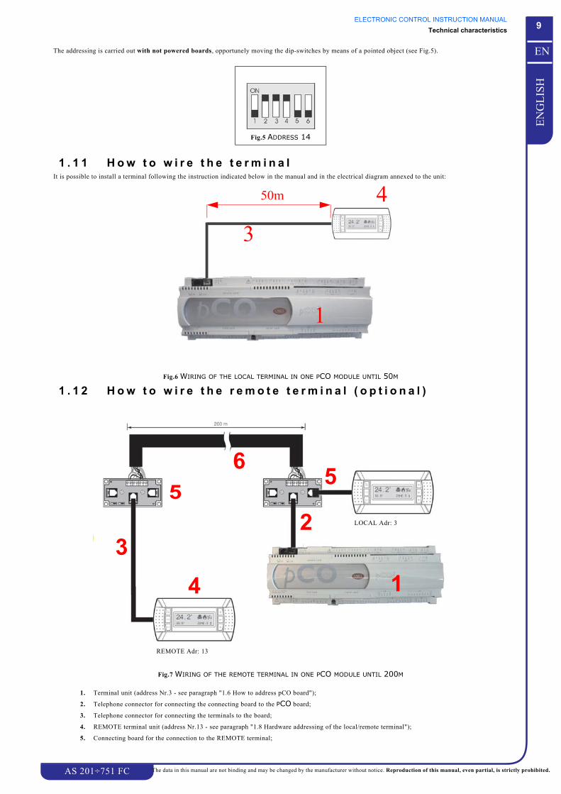
The addressing is carried out with not powered boards, opportunely moving the dip-switches by means of a pointed object (see Fig.5).
1 . 1 1 H o w t o w i r e t h e t e r m i n a lIt is possible to install a terminal following the instruction indicated below in the manual and in the electrical diagram annexed to the unit:
Fig.6 WIRING OF THE LOCAL TERMINAL IN ONE PCO MODULE UNTIL 50M
1 . 1 2 H o w t o w i r e t h e r e m o t e t e r m i n a l ( o p t i o n a l )
Fig.7 WIRING OF THE REMOTE TERMINAL IN ONE PCO MODULE UNTIL 200M
1. Terminal unit (address Nr.3 - see paragraph "1.6 How to address pCO board");
2. Telephone connector for connecting the connecting board to the PCO board;
3. Telephone connector for connecting the terminals to the board;
4. REMOTE terminal unit (address Nr.13 - see paragraph "1.8 Hardware addressing of the local/remote terminal");
5. Connecting board for the connection to the REMOTE terminal;
Fig.5 ADDRESS 14
1
4
3
50m
331
2
4
565
REMOTE Adr: 13
LOCAL Adr: 3

ELECTRONIC CONTROL INSTRUCTION MANUALTechnical characteristics
AS 201÷751 FC
10
EN
GL
ISH
EN
The data in this manual are not binding and may be changed by the manufacturer without notice. Reproduction of this manual, even partial, is strictly prohibited.
6. Screened cable for the wiring of the connecting boards (see Fig.8).
Fig.8 PARTICULAR OF THE SCREENED CABLE

ELECTRONIC CONTROL INSTRUCTION MANUALPressure and temperature transducers
AS 201÷751 FC
11
EN
GL
ISH
EN
The data in this manual are not binding and may be changed by the manufacturer without notice. Reproduction of this manual, even partial, is strictly prohibited.
CHAPTER 2
PRESSURE AND TEMPERATURE TRANSDUCERS2 . 1 P r e s s u r e t r a n s d u c e r s
They are pressure transmitters which are directly powered by pCO (5 Vdc); they have the following specifications:
• working range:for high pressure transducers 0÷34 barg (relative pressure measurement);
• polarised wiring;• output signal (0.5÷4.5V) or (4÷20mA);• linear function in output signal.
Fig.9 OPERATING LOGIC OF TRANSDUCERS
2.1.1 Inspection of the pressure transducer (only 4÷20mA)
DANGERThe operations indicated below can seriously damage the unit electronic control, therefore they must be carried out by specializedpersonnel only.
In the event of any wrong measurement by pressure sensors, before replace them, it is recommended to carry out the following inspections:
• Verify if analogue inputs are suitable to receive signals of 4÷20mA;• Verify the full scales set by software.
These full scales must correspond to the values of transducers, generally 0÷30 barg .• Verify that the capillary of the transducer is not obstructed;• With direct current, measuring by a voltmeter the tension on the heads of the connectors Bn and GND you can indirectly obtain the current of
the probe signal, as the analogue input has an impedance of 50Ω, by applying the formula I=V/R.
The pressure value PS sent by the probe can be obtained in the following way:PS=(Vmis/50-0.004)*(FSmax-FSmin)/0.016+FSminwhere:Vmis= tension measured in Vcc;FSmin= min. full scale of the transducer;FSmax= max. full scale of the transducer.
NOTEIf carried out by a manometer in parallel, this last inspection can indicate if the transducer is sending a wrong pressure or if pCO board isreading wrong values.
2 . 2 T e m p e r a t u r e p r o b e sThey are NTC resistive probes (Negative Temperature Coefficient) that permit nonpolarised wiring.
According to the temperature, their electrical resistance changes as described in Table 1:
Temperature Resistance values
0 °C / +32°F 27.28 kΩ
+20 °C / +68°F 12.00 kΩ
+25 °C / +77°F 10.00 kΩ
+30 °C / +86°F 8.31 kΩ
Table 1 CHARACTERISTICS OF TEMPERATURE TRANSDUCERS
4,5 V / 20 mA
0,5 V / 4 mA
0 max
Tension/Current
Pressure Range

ELECTRONIC CONTROL INSTRUCTION MANUALPressure and temperature transducers
AS 201÷751 FC
12
EN
GL
ISH
EN
The data in this manual are not binding and may be changed by the manufacturer without notice. Reproduction of this manual, even partial, is strictly prohibited.
2 . 3 F u n c t i o n o f t r a n s d u c e r s a n d o f p r o b e sPressure transducers (P) and temperature probes (T) are connected to the appropriate inlets of pCO board.
Each transducer has its own function and is identified by a B associated to a number.
The table below shows the types of transducers and probes and their use.
ATTENTIONThe number of transducers or probes connected to the board depends on the type of unit and is fixed during design phase.
2 . 4 L o c a t i o n o f t r a n s d u c e r sTo identify the temperature and pressure transducers and verify their location, please consult the refrigerant drawing annexed to the manual.
The presence of absence of any transducer depends on the unit type.
pCO analogue input
Connector Name Probe-Transducer Name Description Function
B1 (-BHP1) High press. transm. circuit 1 P
B2 - - -
B3 (-BFCIT) Free Cooling water inlet temperature T
B4 (-BEWIT) Evaporator water inlet temperature T
B5 (-BEWOT) Evaporator water outlet temperature T
B6 (-BLP1) Low pressure transducer 1 P
B7 - - -
B8 (-BAT1) Ambient temperature 1 T
B9 (-BAT2) Ambient temperature 2 T
B10 (-BTOWT) Tank water outlet temperature T

ELECTRONIC CONTROL INSTRUCTION MANUALUtilisation of the terminal
AS 201÷751 FC
13
EN
GL
ISH
EN
The data in this manual are not binding and may be changed by the manufacturer without notice. Reproduction of this manual, even partial, is strictly prohibited.
CHAPTER 3
UTIL ISATION OF THE TERMINAL3 . 1 D i s p l a y o f p C O t e r m i n a l
The display of pCO terminal is used to show the information about the unit status and to change the values of programmable parameters.
The top left corner on the display represents the HOME position of cursor.
At the first start up of the electronic control it is displayed the MAIN mask (see Ref. A1).
However, if during the programming of pCO it is necessary to return to the main mask, it is sufficient to press once or more times k button.
NOTEIf no operation is carried out within 5 minutes the unit will automatically return to the MAIN mask.
The contents of the display are depicted in Fig.10:
Fig.10 MAIN MASKThe display shows many types of masks, distinguished as follows:
R - Read-only masks:used to show the unit status (temperatures, pressures, alarms, etc.).
W - Read-write masks:used to show the values set by programmable parameters and/or to allow their modification.
In read only masks (R) it is only possible to display the parameter values, while in read-write masks (W) it is also possible to modify them (For further
information see manual ahead).
The last row of the MAIN mask informs the user about the status of the unit using one of the messages shown in Table 2:
MESSAGE UNIT STATUS ACTION OBTAINED WITH CONDITION
ON Terminal Unit ON/OFF button The action is not possible if the unit was OFF by digital input ID1 or if the unit was OFF by supervisor.
ON Digital input ID1 powered The action is not possible if the unit was OFF by terminal.
ON By supervisor / By digital input The action is not possible if the unit was OFF by terminal.
OFF Terminal Unit ON/OFF button The action is always possible: this action has priority over any other.
OFF Digital input ID1 not powered The action is possible only if the unit was ON by terminal.If ID1 is activated with unit already OFF, the message will change but LED will remain OFF.
OFF By Supervisor The action is possible only if the unit was ON by terminal.
OFF By daily bands The action is possible only if the daily and weekly bands have been enabled.
OFF Alarm condition The message appears only when it trips an alarm which stops the unit.
OFF By manual procedure The message appears only when the manual procedure has been enabled.
Table 2 MESSAGES ABOUT THE UNIT STATUS
HOME Position
Pre-fixed date and hour (if clock board is present)
Indicator for unit status
Temperature measured by inlet and outlet probe.
ON, it indicates the
FREE COOLING operation
Temperature measured by outlet probe.

ELECTRONIC CONTROL INSTRUCTION MANUALUtilisation of the terminal
AS 201÷751 FC
14
EN
GL
ISH
EN
The data in this manual are not binding and may be changed by the manufacturer without notice. Reproduction of this manual, even partial, is strictly prohibited.
3.1.1 Displaying/signall ing masksIn the electronic control are available other displaying and signalling masks. These masks are displayed after a period of transition during which no button of
pGD is pressed.
NOTETo return to display the main mask press a button of pGD terminal.
This mask appears if no button of pGD is pressed for 10 minutes.In the top left part of the display is shows the temperature regulation value and the unit ON status; the bottom left part shows the temperature regulation setpoint and the current time.
This mask is similar to the previous one, it shows the unit OFF status.
This mask is similar to the previous one, it is displayed only when an alarm trips (the bell flashes).
To display the appropriate alarm press j button (see Chapter 18 “Alarm management“)
When no button of pGD is pressed for 20 minutes it appears the screen saver mask.
Signalling mask: it indicates that unloading procedure is enabled (see Chapter 10 “Compressors Unloading procedure“).
°
°
°
°
°
°

ELECTRONIC CONTROL INSTRUCTION MANUALUtilisation of the terminal
AS 201÷751 FC
15
EN
GL
ISH
EN
The data in this manual are not binding and may be changed by the manufacturer without notice. Reproduction of this manual, even partial, is strictly prohibited.
3 . 2 T e r m i n a l b u t t o n sThe functions of pGD terminal buttons are explained here below:
3.2.1 Function of combined buttons
pGD Description
g + h When the unit is on, if pressed together they switch on and off the unit.
k + f When the unit is on, if pressed together they are used to change the module.
l + j + g When the unit is on, keeping pressed l + j buttons, press many times g button to increase the contrast.
l + j + f When the unit is on, keeping pressed l + j buttons, press many times f button to decrease the contrast.
g + f + h When the unit is on, if pressed together they are used to address the pGD/network.
If pressed once it is utilized to check if in the pCO there is any alarm on.
After removing the alarm cause, a second pressure of this button resets the signalling.j
If pressed once it allows to enter DIRECT loop.
If pressed for more than 5" it allows to enter the configuration modality (password needed).l
Utilized to return from the various menus to the main displaying mask.k
f or
g
Used to move the cursor on the various adjustable fields of a mask.
It allows the access to the selected programming sub-section.
Sometimes it is used to confirm the operation.
h
Used to scroll the various masks of a loop when the cursor is in HOME position.
Used to increase or decrease the value of a numeric field (configuration).
Used to scroll the various sub-sections of a mask.
It allows to scroll the list of sub-sections of a loop.
If pressed during unit normal operation or when unit is in stand-by, it shows the programme version, the
status of compressors, the type of board and the BIOS and BOOT versions.

ELECTRONIC CONTROL INSTRUCTION MANUALUnit starting and stopping
AS 201÷751 FC
16
EN
GL
ISH
EN
The data in this manual are not binding and may be changed by the manufacturer without notice. Reproduction of this manual, even partial, is strictly prohibited.
CHAPTER 4
UNIT STARTING AND STOPPING4 . 1 U n i t s t a r t - u p
When the installation and electrical connections have been made, operate on the unit general switch-breaker (on the electrical panel) putting it in ON position.
The terminal unit is correctly connected to the power supply line when the leds of f, g, h and k buttons lights up and the following mask appears on
the display:
After the network has stabilized, the main mask will be displayed (see Ref. A1).
In these conditions the unit is in STAND-BY.
NOTEEvery time the unit is switched on by means of the main switch-breaker, it is recommended to leave the unit in STAND-BY for a few secondsto allow the pCO net to stabilize.
Press h+g buttons of pGD to switch on the unit and consequently start the setting procedure.
When the unit is switched on the message “ ” will appear on the display.
If the unit doesn’t start, follow the indications below:
• if the remote control is enabled, assure that the digital input 1 of the board is closed (see Ref. E9);
• assure that the unit has not been switched OFF by a Supervisor system (if installed);• assure that the board is correctly connected and addressed;
• the unit must not be in manual operating mode (see Ref. K1);
• there must be no alarm condition.If the problem persists contact the nearest service centre.
4 . 2 A u t o m a t i c r e s t a r tThe electronic control allows to restart automatically the unit after a blackout or after a power failure.
To do this, it is necessary to enter the mask Ref. D3 in USER loop and enable the parameter “ ”.
The automatic restart is possible only if, at power failure, the unit was already ON.
Used Masks:
4 . 3 U n i t s w i t c h i n g o f fTo switch OFF the unit press h+g buttons of pGD terminal.
The unit will stop and the message “ will appear on the display.
In these conditions the unit is in STAND-BY.The antifreeze functions will remain enabled (if they are present).
If necessary, operate on the main breaker-switch of the unit (positioned on the electrical panel) turning it in OFF position.
In these conditions the unit is OFF and not connected to the power supply line.
Ref. D3

ELECTRONIC CONTROL INSTRUCTION MANUALAccess to the programming
AS 201÷751 FC
17
EN
GL
ISH
EN
The data in this manual are not binding and may be changed by the manufacturer without notice. Reproduction of this manual, even partial, is strictly prohibited.
CHAPTER 5
ACCESS TO THE PROGRAMMINGThe electronic control is furnished with two main menus:
1. FREE menu (PASSWORD NOT needed) see "5.1 How to modify a parameter in “Free Menu”"
It can be accessed by pressing and releasing l button.
2. PASSWORD menu (PASSWORD needed) see "5.2 How to modify a parameter of “Password Menu”"
It can be accessed by pressing and releasing for 5 sec. l button.
According to the password inserted, PASSWORD menu is divided in USER, SERVICE and MANUFACTURER.
5 . 1 H o w t o m o d i f y a p a r a m e t e r i n “ F r e e M e n u ”1. Press and release l button on the terminal (see paragraph "3.2 Terminal buttons") to access the loop mask (free menu) (Ref. B1).
ATTENTIONThe selection of the loop or of the parameter happens when the indication becomes negative.
4. After the individuation of the parameter to be modified, press h button to move the cursor on the first parameter of the displayed mask.
If in the mask there is more than one parameter, each time h button is pressed the cursor will move to the next field of the same mask.
5. Modify the value using g or f buttons.
6. Press h button again to confirm the modifying.
If in the mask there is more than one parameter the cursor will move to the following one and, when the last one is reached, the cursor will return
to HOME position.
7. To move to another mask of the loop press g or f button when the cursor is in HOME position.
To access a new loop it is first necessary to return to the loop mask pressing once k button (Ref. B1).
8. To return to MAIN mask (Ref. A2) press twice k button on the terminal.
2. It is possible to scroll the various loops (see " Ref. B1") using
g or f button on the terminal.Ref. B1
3. After selecting the desired loop (e.g. User loop), to access the
mask of this loop (HOME position) press h button.
It will be possible to scroll the masks using g or f button. Ref. B1

ELECTRONIC CONTROL INSTRUCTION MANUALAccess to the programming
AS 201÷751 FC
18
EN
GL
ISH
EN
The data in this manual are not binding and may be changed by the manufacturer without notice. Reproduction of this manual, even partial, is strictly prohibited.
5 . 2 H o w t o m o d i f y a p a r a m e t e r o f “ P a s s w o r d M e n u ”1. Enable the password menu pressing for 5 sec. l button on the terminal (see paragraph "3.2 Terminal buttons");
4. Press h button again to confirm the password.
ATTENTIONThe selection of the loop happens when the indication becomes negative.The access to the loops depends on the password.
7. After the individuation of the parameter to be modified, press h button to move the cursor on the first parameter of the displayed mask.
If in the mask there is more than one parameter, each time h button is pressed the cursor will move to the next field of the same mask.
8. Modify the value using g or f button.
9. Press h button again to confirm the modification.
If in the mask there is more than one parameter the cursor will move to the following one and, when the last one is reached, the cursor will return
to HOME position.
10. To move to another mask of the loop press g or f button when the cursor is in HOME position.
To access a new loop it is first necessary to return to the loop mask pressing once k button (Ref. E2).
11. To return to MAIN mask (Ref. A2) press twice k button on the terminal.
ATTENTIONAll the parameter masks are listed in Chapter 16 or Chapter 17, grouped by LOOP they belong to.They are joined to an alpha-numeric reference, this same number will be used in the rest of this manual to easily individuate thecorresponding mask.
2. The password is requested;
3. Insert the password using g or f button on the terminal;
Ref. F1
5. If the password is wrong, the message “
” will appear, it will be necessary to insert it
again.
If the password is right, the various scrolling loops will be
accessed (Ref. F2);
It is possible to scroll the loops using g or f button on the
terminal.
The loops will be displayed in groups of three.
Ref. F2
6. After having selected the desired loop (e.g. “Modularity”), to
access the mask of this loop (HOME position) press h button.
To scroll the masks use g or f button.
Ref. F2

ELECTRONIC CONTROL INSTRUCTION MANUALAccess to the programming
AS 201÷751 FC
19
EN
GL
ISH
EN
The data in this manual are not binding and may be changed by the manufacturer without notice. Reproduction of this manual, even partial, is strictly prohibited.
5 . 3 H o w t o m o d i f y t h e l a n g u a g eThe pCO allows to choose the language of the masks.
The available languages are: Italian, English, German, French and Spanish.
1. To access User loop follow the same procedure described in chapter
"5.1 How to modify a parameter in “Free Menu”".Ref. B1
2. Reach the mask of languages (Ref. D5) using g or fbutton;
Ref. D5
3. Press h: the cursor starts flashing under the indication of the
current language;Ref. D5
4. Select the desired language using g or f button;
5. Press h to confirm the selected language;
The display automatically displays the main mask translated on the
language selected and, consequently, also all the other masks.
Ref. D5

ELECTRONIC CONTROL INSTRUCTION MANUALMain settings
AS 201÷751 FC
20
EN
GL
ISH
EN
The data in this manual are not binding and may be changed by the manufacturer without notice. Reproduction of this manual, even partial, is strictly prohibited.
CHAPTER 6
MAIN SETTINGSATTENTION
Each unit is delivered ready to work, therefore all the control parameters have been already set during the testing operation and it isn’tnecessary to modify them.On particular cases it is possible to modify the set point and differential values by following the instruction indicated below:
6 . 1 H o w t o m o d i f y t h e s e t p o i n t v a l u e
7. Use g or f buttons to change the value;
8. Press h to store the new value;
9. Press twice k button on the terminal to return to the Main mask.
1. If the unit is off, switch it on by means of the main breaker of the electrical panel
and wait at least one minute to allow pCO net to stabilize;
2. The main mask must be displayed (Ref. A1), it will be similar to the one
shown on the side;Ref. A1
3. Press l button on the terminal:
Free menu will be displayed (Ref. B1);
4. Select Setpoint loop and press h button on the terminal.
Ref. B1
5. The first mask of Setpoint loop will be displayed, scroll the mask using g or fbutton until reaching the mask shown on the side (Ref. C2);
Ref. C2
6. Press h button on the terminal:
the cursor will move on “ ” field.
NOTEThe second setpoint is displayed only if enabled.
Ref. C2

ELECTRONIC CONTROL INSTRUCTION MANUALMain settings
AS 201÷751 FC
21
EN
GL
ISH
EN
The data in this manual are not binding and may be changed by the manufacturer without notice. Reproduction of this manual, even partial, is strictly prohibited.
6 . 2 H o w t o m o d i f y t h e d i f f e r e n t i a l v a l u e
7. Use g or f buttons to change the value;
8. Press h to store the new value;
9. Press twice k button on the terminal to return to the Main mask.
ATTENTIONModify the SETPOINT or the DIFFERENTIAL only if necessary, making sure that they are neither too low nor too high.
DANGERA Summer Setpoint which is too low may cause ice formation so that antifreeze must be added.Generally the differential values must not be too low.If the differential value must be modified, consider also the delays for compressor starts and stops.
1. If the unit is off, switch it on by means of the main breaker of the electrical panel
and wait at least one minute to allow pCO net to stabilize;
2. The main mask must be displayed (Ref. A1), it will be similar to the one
shown on the side;Ref. A1
3. Press l button on the terminal:
Free menu will be displayed (Ref. B1);
4. Select User loop and press h button on the terminal.
Ref. B1
5. The first mask of User loop will be displayed, scroll the mask using g or fbutton until reaching the mask shown on the side (Ref. D1);
Ref. D1
6. Press h button on the terminal:
the cursor will move on “ ” field .Ref. D1

ELECTRONIC CONTROL INSTRUCTION MANUALMain settings
AS 201÷751 FC
22
EN
GL
ISH
EN
The data in this manual are not binding and may be changed by the manufacturer without notice. Reproduction of this manual, even partial, is strictly prohibited.
6 . 3 H o w t o m o d i f y t h e F r e e - C o o l i n g D e l t a a c t i v a t i o n
6. Use g or f buttons to change the value;
7. Press h to store the new value;
8. Press twice k button on the terminal to return to the Main mask.
1. If the unit is OFF, switch it ON by means of the main breaker of the electrical panel
and wait at least one minute to allow pCO net to stabilize;
2. The main mask will be displayed, it will be similar to the one shown on the side
(Ref. A1);Ref. A1
• On the terminal press l for 5 sec. at least then release it;
• Insert the password using f or g buttons and confirm it using h.
The SERVICE password is 01234.If the procedure is right the mask Ref. F2 will appear;
Ref. F2
3. Select the Free Cooling loop and press h to access it.
4. The first mask of Free Cooling loop will be displayed. Scroll the masks using gor f button until reaching the mask shown on the side (Ref. W2);
Ref. W2
5. Press h button on the terminal:
the cursor will position on the field “ ”.
Ref. W2

ELECTRONIC CONTROL INSTRUCTION MANUALTemperature regulation management
AS 201÷751 FC
23
EN
GL
ISH
EN
The data in this manual are not binding and may be changed by the manufacturer without notice. Reproduction of this manual, even partial, is strictly prohibited.
CHAPTER 7
TEMPERATURE REGULATION MANAGEMENTThe electronic control of the ARIES FREE-COOLING units can manage the temperature regulation of the process water:
• “chiller” modality• free-cooling system
The unit normally allows to obtain:
• the cooling of a water volume for a conditioning plant (CHILLER units only);• the heating (by means of a heat recuperator) of a water volume for the sanitary use (CHILLER units only).
As it could happen the contemporary request of heated water by the sanitary plant and of the water (cold) by the conditioning plant, the pCO electronic control
has been designed to satisfy in the best way both the requests.
NOTEFor the Free Cooling system logic consult Chapter 9 “Free-Cooling system management“
7 . 1 W a t e r t e m p e r a t u r e r e g u l a t i o n f o r c o n d i t i o n i n g u s e i n c h i l l e r m o d a l i t y
The pCO allows to set three different ways of temperature regulation (see Ref. V1):
1. the proportional way (P); (NOT UTILIZED)
2. the integral-proportional way (P+I); (NOT UTILIZED)
3. the Neutral Zone way (N.Z.).
7.1.1 NEUTRAL ZONE temperature regulationThe pCO allows to manage the temperature regulation following the Neutral Zone logic.
The Neutral Zone temperature regulation can use the following probes: -BEWIT (inlet) or -BEWOT (evaporator outlet) or -BTOWT (tank outlet).
The temperature interval, included between the setpoint value an the setpoint plus the differential value, (see Ref. C2-Ref. D1) establishes the Neutral
Zone.
To set the Neutral Zone temperature regulation it is sufficient to be sure that “ ” is displayed in the mask “ ” (see Ref. V1).
Set the regulation probe -BEWIT, -BEWOT or -BTOWT (if present) by operating on the mask “ ” (see Ref. G3).
When the unit is in LOCAL operation modality, it is possible to set which probe will be used for the regulation by operating on the mask “
” (see Ref. G3).
The temperature regulation will be considered at evaporator outlet, at evaporator inlet or at tank outlet, according to the selected probe, following Table 3.
When the temperature measured by the probe will be lower than the setpoint value (so under the Neutral Zone) it will be required the stopping of one or more
compressors (the compressors consecutive stopping will be done with a delay time fixed by the parameter “
” see Ref. L2) until the temperature measured will return within the limits of the Neutral Zone.
When the temperature measured by the probe will be higher than the setpoint + differential value (so above the Neutral Zone), it will be required the starting of
one or more compressors (the compressors consecutive starting will be done with a delay time fixed by the parameter “
” see Ref. L1) until the temperature measured will return within the limits of the Neutral Zone.
REGULATION PROBE TEMPERATURE REGULATION
-BEWIT EVAPORATOR INLET
-BEWOT EVAPORATOR OUTLET
-BTOWT TANK OUTLET
Table 3 PROBES UTILIZED FOR THE NEUTRAL ZONE TEMPERATURE REGULATION

ELECTRONIC CONTROL INSTRUCTION MANUALTemperature regulation management
AS 201÷751 FC
24
EN
GL
ISH
EN
The data in this manual are not binding and may be changed by the manufacturer without notice. Reproduction of this manual, even partial, is strictly prohibited.
The graphic of Fig.11 explains how the increasing or decreasing requirement of “cold” fixes the compressors starting or stopping, following the logic of the
Neutral Zone.
Fig.11 CHILLER NEUTRAL ZONE LOGIC
For setpoint and differential setting enter parameters Ref. C2-Ref. D1.
To set the delay time between the compressors staring or stopping enter parameters Ref. L1, Ref. L2.
It is also possible to set the parameter “ ” (see Ref. L3) which allows to start a compressor
when the water temperature value remains within the neutral zone for a time longer than the preset one.
This allows to obtain an homogeneous compressor starting distribution, avoiding situations during which only some compressors remain in operation for a long
time and others will be started only for short periods and, consequently, to force the system when the setpoint temperature is reached.
Used masks:
Ref. L1 Ref. L2
Ref. L3 Ref. D1
Ref. G3 Ref. H1
Ref. C2 Ref. V1
Ref. L1 Ref. L1
COMPRESSORS
TIME
Compr. OFF
Compr. 1 ON
Compr. 2 ON
WATER TEMPERATURE
TIME
SET
SET+DIFF.
STATUS
NEUTRAL ZONE (see Ref. C2-Ref. D1)
BEWIT

ELECTRONIC CONTROL INSTRUCTION MANUALTemperature regulation management
AS 201÷751 FC
25
EN
GL
ISH
EN
The data in this manual are not binding and may be changed by the manufacturer without notice. Reproduction of this manual, even partial, is strictly prohibited.
7 . 2 W a t e r t e m p e r a t u r e r e g u l a t i o n i n F R E E - C O O L I N G m o d u s
The Free-Cooling system can be utilized only if the ambient temperature is lower than the temperature of the inlet process water. In this way the process water
can be cooled, partially or completely, by the ambient air in order to allow an important energy saving (the refrigerant compressors and the condensing fans
stop).
The Free-Cooling system is enabled when:
Tamb BFICT-∆where:
Tamb is the medium temperature measured by BAT probe;
BFICT is the temperature measured by the probe at Free-Cooling inlet
∆ is the Free-Cooling activation delta
The Free-Cooling temperature regulation with the Neutral Zone follows the same logic of the chiller modus (see paragraph above).
When the process water temperature is lower than the setpoint value (under the Neutral Zone), the Free-Cooling system will gradually stop, until the temperature
will reach again the Neutral Zone.
When the process water temperature is higher than setpoint+differential (over the Neutral Zone), the Free-Cooling system will be increased, until the temperature
value will reach again the Neutral Zone.
The following graphic Fig.12 shows the Free-Cooling Neutral Zone logic.
Fig.12 FREE-COOLING NEUTRAL ZONE LOGIC
To set the setpoint and the differential see the parameter Ref. C2, Ref. D1.
NOTEIf the Free-Cooling system is working at 100% of its capacity (three-way-valve open and free-cooling fans on), and this will not be enoughto satisfy the cool request, the “chiller” (fans and compressors start up) modus will start operating as explained in paragraph "7.1 Watertemperature regulation for conditioning use in chiller modality".
For further information about the Free-Cooling system see Capitolo 9 “Gestione del funzionamento del sistema Free-Cooling“.
FREE-COOLING
TIME
WATER TEMPERATURE
TIME
SET
SET+DIFF.
STATUS
NEUTRAL ZONE (see Ref. C2, Ref. D1)
Free-cooling
FREE-COOLLING ON
ON
Free-coolingOFF
TIME
FREE-COOLING
INCREASE
FREE-COOLING
PERFORMANCE
UPKEEP
FREE-COOLING
INCREASEFREE-COOLING
PERFORMANCE
UPKEEP
FREE-COOLING
DECREASE

ELECTRONIC CONTROL INSTRUCTION MANUALTemperature regulation management
AS 201÷751 FC
26
EN
GL
ISH
EN
The data in this manual are not binding and may be changed by the manufacturer without notice. Reproduction of this manual, even partial, is strictly prohibited.
7 . 3 A n t i - f r e e z e c o n t r o lThe anti-freeze control depends on the temperature measured at the evaporator outlet (-BEWOT probe).
When the temperature decreases below the preset antifreeze threshold (see Ref. Q3) the pCO will produce an alarm which will block the unit (see Ref. AM19).
It will persist until the temperature increases and reaches a value higher than setpoint + differential (see Fig.13).
The differential value cannot be changed and it is of 4°C.The anti-freeze alarm stops all the connected devices except for the pump.
Fig.13 ANTIFREEZE CONTROL LOGIC
NOTETo lower the freeze protection setpoint, modify mask Q3 and add a suitable amount of antifreeze solutions to the system. If in doubt, contactthe MTA after-sales service.
Used masks:
Ref. G6 Ref. Q3
ALARM STATUS
TEMPERATURE
ON
BY B2MEASURED
OFF
ALARM
DIFFERENTIAL
SETPOINT
LOW TEMPERATURE OF WATER
AT EVAPORATOR OUTLET

ELECTRONIC CONTROL INSTRUCTION MANUALSetpoint management
AS 201÷751 FC
27
EN
GL
ISH
EN
The data in this manual are not binding and may be changed by the manufacturer without notice. Reproduction of this manual, even partial, is strictly prohibited.
CHAPTER 8
SETPOINT MANAGEMENT
NOTEThis chapter explains the setpoint management logic for chiller units only.For Free-Cooling operating logic please consult Chapter 9 “Free-Cooling system management“.
Modifying the mask “ ” (see Ref. V1) pCO electronic control can manage the setpoint in five different ways:
• fixed setpoint;• compensated setpoint;• double setpoint;• adjustable setpoint by daily bands;• setpoint by analogue input.
Used masks:
8 . 1 F i x e d s e t p o i n tpCO electronic control manages the water temperature regulation according to a setpoint (Ref. C2) and to a fixed differential (Ref. D1), which can not
be modified by external causes.
Used masks:
8 . 2 C o m p e n s a t e d s e t p o i n tThe compensated setpoint is calculated according to the external temperature measured by -BAT1 probe and according to the values of parameters “
” (Ref. C3) and “ ” (Ref. C4).
The graphic below shows the setpoint state according to the settings of the parameters:
Graphic with positive “ ” value;
Ref. V1
Ref. C2 Ref. D1

ELECTRONIC CONTROL INSTRUCTION MANUALSetpoint management
AS 201÷751 FC
28
EN
GL
ISH
EN
The data in this manual are not binding and may be changed by the manufacturer without notice. Reproduction of this manual, even partial, is strictly prohibited.
Graphic with negative “ ” value;
Used masks:
8 . 3 D o u b l e s e t p o i n tIt is possible to fix a second operating setpoint. Commute the digital input on the electronic board (see wiring diagram) to choose the setpoint.
Used masks:
8 . 4 A d j u s t a b l e s e t p o i n t b y d a i l y b a n d sDuring the operation with adjustable setpoint by daily bands it is possible to programme four daily bands with their different setpoints. At preset time, the
electronic control will change the unit setpoint according to the preset settings.
Used masks:
Ref. C3 Ref. C4
Ref. C2
Ref. C5 Ref. C6
Ref. C7 Ref. C8
!"#$! !"#

ELECTRONIC CONTROL INSTRUCTION MANUALFree-Cooling system management
AS 201÷751 FC
29
EN
GL
ISH
EN
The data in this manual are not binding and may be changed by the manufacturer without notice. Reproduction of this manual, even partial, is strictly prohibited.
CHAPTER 9
FREE-COOLING SYSTEM MANAGEMENTThe pCO control manages the Free-Cooling system.
It activates or deactivates the Free-Cooling system according to the medium ambient temperature “Tamb”, which is checked by the BAT1 and BAT2 probes and
the unit inlet water temperature “Tin FC”, which is checked by the BFCIT probe.
With the Free-Cooling it is possible to pre-cool the water by fins coils.
If the ambient conditions are not available to active the Free-Cooling system, the chiller will work normally.
Here below you can see the hydraulic circuit of the unit:
9 . 1 O p e r a t i n g l o g i cThe pCO is enabled to manage the Free-Cooling system by the mask Ref. W1.
The electronic control will active the Free-Cooling system when:
Tamb BFCIT - ∆
where:
Tamb = is the medium ambient temperature detected by the probes (BAT1- BAT2)
BFCIT = is the water inlet temperature detected by the BFCIT probe.
∆ = temperature difference to enable the Free-Cooling system, its value is set in the parameter Ref. W2.
The Free-Cooling activation condition must persist for the time set in the parameter Ref. W3.
When all conditions are respected, the pCO turns off the compressors and starts modulating the three-way-valve following the Neutral Zone temperature
regulation, see paragraph "7.2 Water temperature regulation in FREE-COOLING modus".
If the three-way-valve is completely open, and this will not be enough to bring the temperature back within the “neutral zone”, the fans will start up according to
the logic explained in the paragraph "11.3 Free Cooling fans".
When the fans reach the maximum speed, the electronic control will start up the compressor/s and/or the capacity control according to the logic explained in
paragraph "7.1 Water temperature regulation for conditioning use in chiller modality".
The Free-Cooling system will stop operating when Tamb BFCIT - ∆ and this condition is detected for the time set in the parameter Ref. W3.
EVAPORATOR
ELECTRONIC CONTROL INSTRUCTION MANUALFree-Cooling system management
AS 201÷751 FC
30
EN
GL
ISH
EN
The data in this manual are not binding and may be changed by the manufacturer without notice. Reproduction of this manual, even partial, is strictly prohibited.
Used Masks:
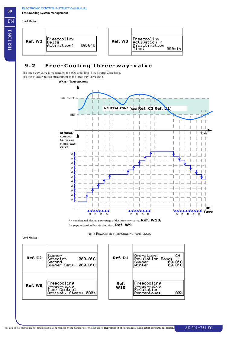
9 . 2 F r e e - C o o l i n g t h r e e - w a y - v a l v eThe three-way-valve is managed by the pCO according to the Neutral Zone logic.
The Fig.14 describes the management of the three-way-valve logic.
Fig.14 REGULATED FREE-COOLING FANS LOGICUsed Masks:
Ref. W2 Ref. W3
Ref. C2 Ref. D1
Ref. W9 Ref. W10
TEMPO
WATER TEMPERATURE
TIME
SET
SET+DIFF.
OPENING/
NEUTRAL ZONE (see Ref. C2-Ref. D1)
AA
AA
AA
AA
AA
A
% OF THE
B B B B B B B B B B B B B
A= opening and closing percentage of the three-way-valve, Ref. W10;
B= steps activation/deactivation time, Ref. W9
THREE-WAY
CLOSING
VALVE

ELECTRONIC CONTROL INSTRUCTION MANUALFree-Cooling system management
AS 201÷751 FC
31
EN
GL
ISH
EN
The data in this manual are not binding and may be changed by the manufacturer without notice. Reproduction of this manual, even partial, is strictly prohibited.
When the temperature detected by the probe is lower than the setpoint value (under the Neutral Zone), the pCO start closing the three-way-valve (“A”
corresponds to the decrees value Ref. W10 “B” is the time value Ref. W9) until the valve will be completely closed, or the temperature will go back
within the Neutral Zone.
When the temperature detected by the probe is higher than the setpoint value + differential (over the Neutral Zone), the pCO start opening the three-way-valve
(“A” corresponds to the decrees value Ref. W10 “B” is the time value Ref. W9) until the three-way-valve will be completely open, or the detected
temperature will go back within the Neutral Zone.
ELECTRONIC CONTROL INSTRUCTION MANUALManagement of compressors operation
AS 201÷751 FC
32
EN
GL
ISH
EN
The data in this manual are not binding and may be changed by the manufacturer without notice. Reproduction of this manual, even partial, is strictly prohibited.
CHAPTER 10
MANAGEMENT OF COMPRESSORS OPERATION1 0 . 1 U n i t t y p e a n d c o m p r e s s o r n u m b e rATTENTION
The unit type and compressor number exclusively depend on the unit manufacturing characteristics.The parameters which configure the unit type and the compressor number are directly set by the manufacturer and absolutely must not bemodified.Their modification, carried out by not qualified personnel, could seriously damage the unit operation.
Each pCO module is programmed setting both the type of unit and the global number of compressors.
The type of unit can be selected by the mask “ ”, accessible into “ ” (see Ref. G1).
The type of unit can be:
Single-circuit N°2 Scroll Comp.: if the unit is single-circuit with two SCROLL compressors
Single-circuit N°3 Scroll Comp.: if the unit is single-circuit with three SCROLL compressors
Single-circuit N°1 Semi hermetic + Part. Comp.: if the unit is single-circuit with a Semi hermetic and chocked compressor (ONLY SPECIAL UNITS)
Single-circuit N°1 SCREW Compressor: if the unit is single-circuit with a SCREW compressor (ONLY SPECIAL UNITS)
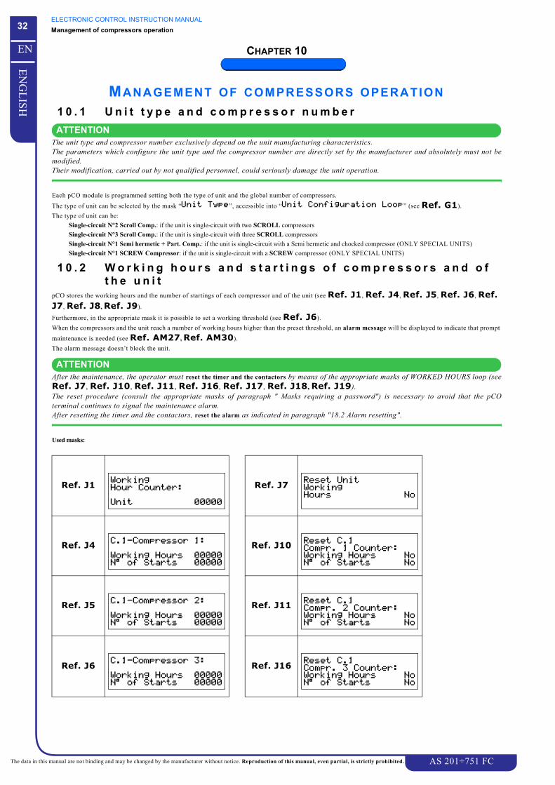
1 0 . 2 W o r k i n g h o u r s a n d s t a r t i n g s o f c o m p r e s s o r s a n d o f t h e u n i t
pCO stores the working hours and the number of startings of each compressor and of the unit (see Ref. J1, Ref. J4, Ref. J5, Ref. J6, Ref. J7, Ref. J8, Ref. J9).
Furthermore, in the appropriate mask it is possible to set a working threshold (see Ref. J6).
When the compressors and the unit reach a number of working hours higher than the preset threshold, an alarm message will be displayed to indicate that prompt
maintenance is needed (see Ref. AM27, Ref. AM30).
The alarm message doesn’t block the unit.
ATTENTIONAfter the maintenance, the operator must reset the timer and the contactors by means of the appropriate masks of WORKED HOURS loop (seeRef. J7, Ref. J10, Ref. J11, Ref. J16, Ref. J17, Ref. J18, Ref. J19).The reset procedure (consult the appropriate masks of paragraph " Masks requiring a password") is necessary to avoid that the pCOterminal continues to signal the maintenance alarm.After resetting the timer and the contactors, reset the alarm as indicated in paragraph "18.2 Alarm resetting".
Used masks:
Ref. J1 Ref. J7
Ref. J4 Ref. J10
Ref. J5 Ref. J11
Ref. J6 Ref. J16
#!%#& %
#!%#& '
#!%#& (

ELECTRONIC CONTROL INSTRUCTION MANUALManagement of compressors operation
AS 201÷751 FC
33
EN
GL
ISH
EN
The data in this manual are not binding and may be changed by the manufacturer without notice. Reproduction of this manual, even partial, is strictly prohibited.
1 0 . 3 C o m p r e s s o r s s e q u e n c i n g p r o c e d u r eThe sequencing procedure consists on the starting/stopping of compressors following a logic which allows all compressors to operate at the same number of
hours.
The compressors sequencing procedure is enabled when the parameter “ ” (see Ref. G3) is set as “ ”, and
is disabled when this parameter is set as “ ”.
The compressors sequencing procedure will help to guarantee all compressors long life.
Used masks:
10.3.1 Compressor sequencing procedure disabled
DANGERThe sequencing procedure of compressors must NEVER be disabled.However, pCO allows to set the parameter “ ” as “ ”.This setting can be used only in some particular situations, referred to special units, and must not be used in standard unitsbecause it could cause the unit to malfunction.
On the graphic of Fig.15 is explained an example of starting and stopping logic during the first start-up of a two compressors unit with sequencing procedure
disabled.
The following graphic shows the insertion of compressors, according to the water inlet temperature, starting from a situation of unit completely stopped.
Fig.15 GRAPHIC OF THE COMPRESSORS SEQUENCING PROCEDURE DISABLED
Ref. G3 BEWIT
SET: see Ref. C2DIF: see Ref. D1
Time
Water Temperature
SET
SET+DIFF
DIFF/2
Unit s
topped
Firs
t st
art
-up
CIR
CU
IT 1
com
pr.
1
SINGLE-CIRCUIT UNIT
com
pr.
2
Not capacity controlled compr.OFF
ON
WITH TWO COMPRESSORS

ELECTRONIC CONTROL INSTRUCTION MANUALManagement of compressors operation
AS 201÷751 FC
34
EN
GL
ISH
EN
The data in this manual are not binding and may be changed by the manufacturer without notice. Reproduction of this manual, even partial, is strictly prohibited.
10.3.2 Sequencing procedure “per compressor”This procedure manages all compressors starting and stopping following the FIFO logic: that is, in the event of cold request the first compressor started, when
this request decreases, will be the first stopped.
At the following request the compressor that has been idle for more time, will start.
On the graphic of Fig.16 is explained an example of starting and stopping during the first start-up of a two compressors unit without capacity control.
The following graphic explains the compressors sequencing logic, according to the water inlet temperature, starting from a situation of completely stopped unit.
Fig.16 GRAPHIC OF THE COMPRESSORS SEQUENCING PROCEDURE ENABLED
1 0 . 4 C o m p r e s s o r s P u m p - D o w n p r o c e d u r e ( o n l y A S 3 5 1 ÷ 7 5 1 F C u n i t s )
If Pump-Down procedure is enabled (see Ref. G13), the last operating compressor will be stopped following the modality described below. This procedure
is used to avoid that compressors suck refrigerant at liquid state, during the successive unit starting.
When the last compressor stopping is requested, the Pump-Down procedure starts by switching on a solenoid-valve which closes the refrigerant circuit just after
the condenser.
When the preset low pressure threshold will be reached (see Ref. G14) the compressor will be stopped.
After a delay time set by a certain parameter (see Ref. G14), the low pressure threshold could not be reached.
In this case, the compressor will stop and will cause a Wrong Pump-Down alarm tripping (see Ref. AM14, Ref. AM28) which stops the interested
circuit.
The pump-down, if enabled, is carried out even if the unit is in OFF status, by pressing h + g buttons of pCO terminal.
SET: see Ref. C2DIF: see Ref. D1
Time
Water Temperature
SET
SET+DIFF
DIFF/2
Unit s
topped
Firs
t st
art
-up
CIR
CU
IT 1
com
pr.
1
SINGLE-CIRCUIT UNIT
com
pr.
2
Not capacity controlled compr.OFF
ON
WITH TWO COMPRESSORS

ELECTRONIC CONTROL INSTRUCTION MANUALManagement of compressors operation
AS 201÷751 FC
35
EN
GL
ISH
EN
The data in this manual are not binding and may be changed by the manufacturer without notice. Reproduction of this manual, even partial, is strictly prohibited.
The following graphics explain Pump-Down procedure logic:
Fig.17 PUMP-DOWN LOGIC
Warm Request
Time
SI
NO
Refrigerant Solenoid Valve
Time
ON
OFF
Compressor
Time
ON
OFF
Compressor
Time
ON
OFF
Refrigerant Pressure
Time
PRESSURE AT THE END OF
PUMP-DOWN
AB
case
Aca
se B
compressor stopping for low pressure level
compressor stopping for
reached
max. time reached withthe tripping of Wrong Pump-Down Alarm

ELECTRONIC CONTROL INSTRUCTION MANUALManagement of compressors operation
AS 201÷751 FC
36
EN
GL
ISH
EN
The data in this manual are not binding and may be changed by the manufacturer without notice. Reproduction of this manual, even partial, is strictly prohibited.
Used masks:
1 0 . 5 C o m p r e s s o r s U n l o a d i n g p r o c e d u r eThis procedure is needed during peak periods of cooling requirements, for example when the unit has not been started for a long period of time.
In these conditions, the water temperature at evaporator inlet could be excessively high to request a refrigerant rating higher than the one designed for the unit.
The unit overload could cause the tripping of all compressors which must work at extreme conditions.
The overloaded compressors could overheat and cause the tripping of thermal protections, or the refrigerant gas pressure could reach alarm levels which will
block the unit.
pCO will allow to avoid these problems by unloading procedure. This procedure will cause the forced exclusion of one compressor for each circuit, until the
alarm condition stops.
The unloading is carried out without considering the temperature regulation, the sequencing procedure and the min. time for the capacity control of the
compressors.
The unit will slowly return to normal operating conditions, without exceeding its capacities.
Table 4 indicates the outlets interested by unloading for all the unit configurations.
If the unloading is requested, the interested compressor is immediately disabled, without considering the sequencing procedure, the temperature regulation and
the min. time for compressor starting.
NOTEAt the following starting of the compressors, stopped for unloading, the delays related with the compressors or the delay of the capacitycontrol enabling will be always respected.
The compressors exclusion by unloading procedure can be established by temperature values measured by -BEWIT probe (see Ref. E1) or by pressure
values measured by -BHP1 and -BHP2 high transducers (see Ref. E3).
Ref. G13
Ref. G14
Ref. G9
UNIT TYPE UNLOADING OF CIRCUIT 1
2 Scroll compressors the compressor 2 is put in OFF
3 Scroll compressors the compressor 3 is put in OFF
Table 4 COMPRESSORS INTERESTED BY UNLOADING
# %
# %)*%+

ELECTRONIC CONTROL INSTRUCTION MANUALManagement of compressors operation
AS 201÷751 FC
37
EN
GL
ISH
EN
The data in this manual are not binding and may be changed by the manufacturer without notice. Reproduction of this manual, even partial, is strictly prohibited.
10.5.1 Unloading procedure by high pressure probesIt is possible by setting a pressure setpoint, a differential and an Unloading time (see Ref. O2 and Ref. O3).
The Unloading procedure, which follows the logic explained on the graphic of Fig.18, starts when the pressure measured by high pressure transducers is higher
than or equal to the prefixed setpoint.
The procedures stops if:
A the pressure, measured during Unloading time, decreases under the Set - Differential value.
B after Unloading time, the pressure is lower than the prefixed setpoint.
Fig.18 OPERATING LOGIC OF UNLOADING BY HIGH PRESSURE PROBES
Used masks:
Ref. O2 Ref. O3
Ref. G7
High pressure probes
Time
SET
Unloading Procedure
Time
ON
OFF
SET-DIFF
ON
OFF
Unloading time
A
B
case
Aca
se B
Unloading time
# %),%+

ELECTRONIC CONTROL INSTRUCTION MANUALFans operation management
AS 201÷751 FC
38
EN
GL
ISH
EN
The data in this manual are not binding and may be changed by the manufacturer without notice. Reproduction of this manual, even partial, is strictly prohibited.
CHAPTER 11
FANS OPERATION MANAGEMENTThere are always two independent and separate groups of fans, one is connected to the refrigerant circuit and the other one to the Free Cooling circuit (see figure
below).
The condensing fans are activated according to the pressure detected by the high pressure transducers (-BHP1).
The Free Cooling fans are activated according to the cool request (Neutral Zone temperature regulation) detected by the probe (-BTOWT if the tank is present, -
BEWOT or -BEWIT). For further information see Chapter 9 “Free-Cooling system management“.
1 1 . 1 C o n d e n s i n g F a n sHigh pressure transducers connected to pCO board (see paragraph "2.1 Pressure transducers") can be used to manage the fans in three ways The enabling of fans
is fixed according to the pressures measured by high pressure transducers of the circuit.
11.1.1 Management by stepDuring step regulation, the unit fans are divided in two subgroups composed of one or more fans.
This subdivision is fixed during design phase and depends on the way the electrical connections of fans have been carried out (consult the wiring diagram of the
unit).
The activation of one fans step corresponds to the starting of one fans subgroup.
The Fig.19 describes the two fans step management logic (see Ref. N3-Ref. N4Ref. N5, Ref. N6, Ref. N9).
For each of the two steps can be set a proper setpoint value (Set 1, Set2); the differential (Diff) can be set for the first step, for the second step it is calculated by
the electronic control (Diff1).
Fig.19 FANS ENABLING LOGIC BY STEPUsed masks:
Ref. N3 Ref. N4
Ref. N1
CO
ND
EN
SIN
G
ELE
CT
RIC
BO
AR
D
FREE C
OO
LIN
G
FAN
SFA
NS
FAN STATUS
VALUE MEASURED
ON
STEP 2
STEP 1
TRANSDUCERS
BY HIGH PRESSURE
ON 2nd fans
subgroup
1st fanssubgroup
OFF
OFF
OFF
1
-& % !-& ' !
! -& #

ELECTRONIC CONTROL INSTRUCTION MANUALFans operation management
AS 201÷751 FC
39
EN
GL
ISH
EN
The data in this manual are not binding and may be changed by the manufacturer without notice. Reproduction of this manual, even partial, is strictly prohibited.
11.1.2 Management by variable speedThe speed of the fans can be modified (see Ref. N1) using a phase-cutting regulator managed by pCO.
To determine the min. and max. speed of fans, pCO uses the parameters of mask Ref. N7, the pressure setpoint and the differential (see Ref. N7-Ref. N9, Ref. N10).
The fans speed regulation is carried out only if the following conditions are respected, otherwise the fans will remain off:
• The unit is in ON status and at least one compressor is in ON.• No alarm condition referred to the fan is present:
Fan overload / Anomaly on the speed regulator.During normal operation the fans are stopped when the pressure measured by the high pressure transducer (-BHP1) is lower than Set or when the last operating
compressor of the unit is stopped.
Furthermore, it is possible to fix two differentials (Diff and Diff1) where Diff is used for daily operation and Diff1 for nightly operation.
Fig.20 describes the operating logic of fans speed regulation.
Fig.20 FANS ENABLING LOGIC BY SPEED REGULATORThe starting of fans by variable speed regulation is influenced also by the settings described in the paragraph "11.1.4 Speed-Up time logic".
Used masks:
11.1.3 Management by variable speed on the medium valueThe fan speed can be adjusted on the pressure medium value (see Ref. N1).
To fix the min. and max. speed of fans, pCO uses the parameters of mask Ref. N7, the pressure setpoint and the differential (see Ref. N12).
pCO stores immediately the pressure values measured by the transducer(-BHP1) creating a value storing loop. The medium value among these stored values will
give the pressure value used to calculate the fans speed.
At compressor starting, this regulation can be carried out after an adjustable delay time (Ref. N11). It will continue until the medium pressure reaches the
regulation threshold on the actual value.
When the variable speed regulation on the pressure medium value is not enabled, pCO regulates the fans following the variable speed regulation logic (see
paragraph "11.1.2 Management by variable speed").
Ref. N1 Ref. N7
Ref. N9 Ref. N10
FANS SPEED
VALUE MEASURED BY
HIGH PRESSURESet Set+Diff
fans ON
fans OFF
% of the max.speed
% of the min.speed
TRANSDUCERS
Diff
Set+Diff1Diff1
! -& #
-& # " !! #"$ !! #
-& # -& !$! !
-& # %

ELECTRONIC CONTROL INSTRUCTION MANUALFans operation management
AS 201÷751 FC
40
EN
GL
ISH
EN
The data in this manual are not binding and may be changed by the manufacturer without notice. Reproduction of this manual, even partial, is strictly prohibited.
Used masks:
11.1.4 Speed-Up t ime logicThe Speed-Up time logic can be used only if the fan operation is set as “ ” or “ ” (see Ref. N1).
The characteristics of the normally used fans don’t allow their starting when the parameter “ ” is set
to a too low value.
The problem depends on the initial current reduction to start-up fans which, in these conditions, is too low.
The problem has been solved using the parameters “ ” and “ ”, used when the starting of
fans is requested.
These parameters allow to fix a period of time during which the fan rotation speed is forced to the value set “ ” (see
Ref. N8).
After “ ” the speed will be reduced according to the setting of parameter “ ”.
Fig.21 shows the Speed-Up time logic.
Fig.21 SPEED-UP TIME LOGIC
Therefore, if “ ” is set as zero, it will not be possible to start the fans with a value “
” set to a value lower than 30% for “SSN” versions and under 50% for “N” versions.
Used masks:
Ref. N1 Ref. N7
Ref. N11
Ref. N12
Ref. N1 Ref. N8
! -& #
-& # " !! #"$ !! #
-& . # &' ! (
-& . # -& !$! !
FAN SPEED
TIME
fans ON
fans OFF
min. speed
fans ONper cent speed in speed-up
! -& #
-& # ) ! ) '( #

ELECTRONIC CONTROL INSTRUCTION MANUALFans operation management
AS 201÷751 FC
41
EN
GL
ISH
EN
The data in this manual are not binding and may be changed by the manufacturer without notice. Reproduction of this manual, even partial, is strictly prohibited.
1 1 . 2 N i g h t l y o p e r a t i o npCO control can manage the fans in nightly modality by enabling the parameter “Low Noise” (see Ref. N2).
This modality allows, at a certain adjustable hour (see Ref. R2), to decrease the max. number of fan turning in order to reduce the noise level.
Used masks:
1 1 . 3 F r e e C o o l i n g f a n sThe Free-Cooling fans activation/disactivation depends on the Neutral Zone temperature regulation.
The probes -BTOWT, -BEWOT or -BEWIT are connected to the pCO board (see paragraph "2.1 Trasduttori di pressione"), and can be utilized to manage the
Free-Cooling coils fans in two different ways :
• by steps• by variable speed (regulated)
ATTENTIONThe fans can be activated only if the Free-cooling system is on and the three-ways-valve in completely open.
During the normal operation the fans work according to the Neutral Zone temperature regulation.
In the graphic of Fig.22 and Fig.23 it is possible to see the fans operation with neutral zone.
If the temperature checked by the regulation probe (BEWOT, BEWIT or BEWOT see Ref. G3) is lower than the setpoint value (Ref. C2) (under the
Neutral Zone) the free-cooling fans stop, while if the temperature is higher than the setpoint value (Ref. C2) + differential (Ref. D1) (over the Neutral
Zone), the free-cooling fans start up.
The fans operation depends on their management modus (by steps, regulated Ref. W4) as explained below.
Used Masks:
The fans speed regulation is carried out only if the following conditions are respected, otherwise the fans will remain off:
• The unit and the free-cooling coil are ON• fans start up depends on the free-cooling coils• Any alarm condition referred to the free-cooling circuit fan:
- Fan overload- Anomaly on the speed regulator (regulated only)
Ref. N1 Ref. N2
Ref. N5 Ref. N6
Ref. N10
Ref. N21
Ref. R2
Ref. C2 Ref. D1
Ref. G3
! -& #
* + ( , +
% -& % !-& ' !
%
-& # %
- . % /& '
BEWIT

ELECTRONIC CONTROL INSTRUCTION MANUALFans operation management
AS 201÷751 FC
42
EN
GL
ISH
EN
The data in this manual are not binding and may be changed by the manufacturer without notice. Reproduction of this manual, even partial, is strictly prohibited.
During step regulation, the unit fans are divided in three subgroups composed of one or more fans.
This subdivision is fixed during design phase and depends on the way the electrical connections of fans have been carried out (consult the wiring diagram of the
unit).
The activation of one fans step corresponds to the starting of one fans subgroup.
The Fig.22 describes the three fans step management logic.
The parameter Ref. W5 set a delay time between two steps.
Fig.22 FREE-COOLING FANS GROUP ACTIVATION LOGICUsed Masks:
11.3.1 FC fans regulated by variable speedThe speed of the fans can be modified using a phase-cutting regulator managed pCO.
The pCO utilizes the following parameters to:
• set the min. and max. fans speed, mask Ref. W7;
• set the fans speed increase or decrease, mask Ref. W6;
• set the steps activation time (% of increase), mask Ref. W5.
During normal operation the fans are managed according to the Neutral Zone temperature regulation.
Ref. W5
Ref. W5 Ref. W5
FANS
TIME
Fan OFF
Fan ON
Fan ON
WATER TEMPERATURE
TIME
SET
SET+DIFF.
STATUS
NEUTRAL ZONE (see Ref. C2-Ref. D1)
Group 1
Group 1
Group 2
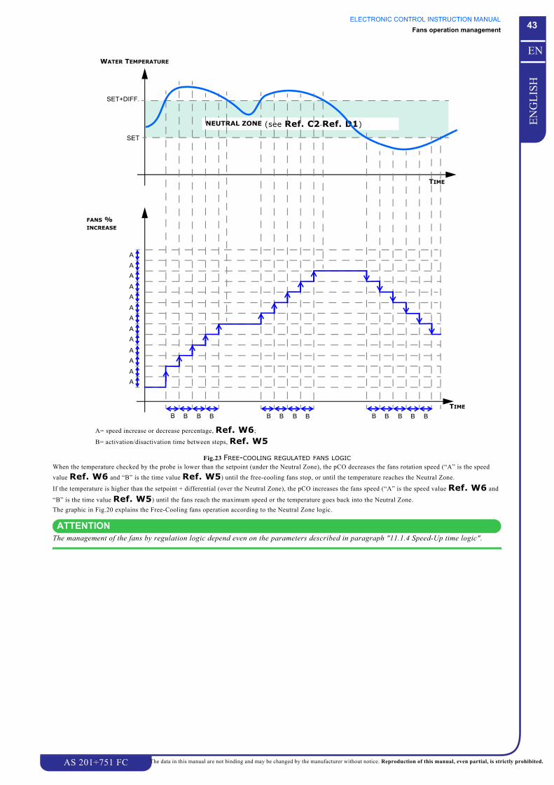
ELECTRONIC CONTROL INSTRUCTION MANUALFans operation management
AS 201÷751 FC
43
EN
GL
ISH
EN
The data in this manual are not binding and may be changed by the manufacturer without notice. Reproduction of this manual, even partial, is strictly prohibited.
Fig.23 FREE-COOLING REGULATED FANS LOGICWhen the temperature checked by the probe is lower than the setpoint (under the Neutral Zone), the pCO decreases the fans rotation speed (“A” is the speed
value Ref. W6 and “B” is the time value Ref. W5) until the free-cooling fans stop, or until the temperature reaches the Neutral Zone.
If the temperature is higher than the setpoint + differential (over the Neutral Zone), the pCO increases the fans speed (“A” is the speed value Ref. W6 and
“B” is the time value Ref. W5) until the fans reach the maximum speed or the temperature goes back into the Neutral Zone.
The graphic in Fig.20 explains the Free-Cooling fans operation according to the Neutral Zone logic.
ATTENTIONThe management of the fans by regulation logic depend even on the parameters described in paragraph "11.1.4 Speed-Up time logic".
TIME
WATER TEMPERATURE
TIME
SET
SET+DIFF.
FANS %
NEUTRAL ZONE (see Ref. C2-Ref. D1)
AA
AA
AA
AA
AA
AAA
INCREASE
B B B B B B B B B B B B B
A= speed increase or decrease percentage, Ref. W6;
B= activation/disactivation time between steps, Ref. W5

ELECTRONIC CONTROL INSTRUCTION MANUALFans operation management
AS 201÷751 FC
44
EN
GL
ISH
EN
The data in this manual are not binding and may be changed by the manufacturer without notice. Reproduction of this manual, even partial, is strictly prohibited.
Used Masks:
Ref. W5 Ref. W6
Ref. W7
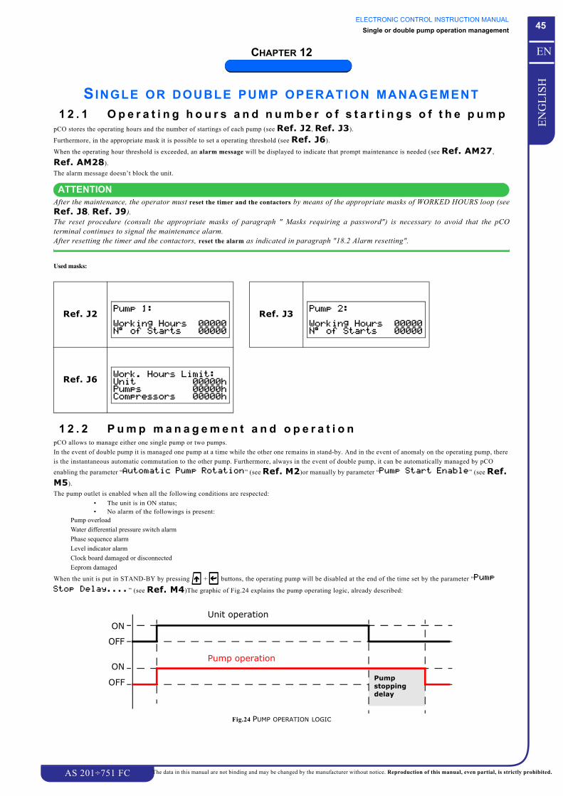
ELECTRONIC CONTROL INSTRUCTION MANUALSingle or double pump operation management
AS 201÷751 FC
45
EN
GL
ISH
EN
The data in this manual are not binding and may be changed by the manufacturer without notice. Reproduction of this manual, even partial, is strictly prohibited.
CHAPTER 12
SINGLE OR DOUBLE PUMP OPERATION MANAGEMENT1 2 . 1 O p e r a t i n g h o u r s a n d n u m b e r o f s t a r t i n g s o f t h e p u m p
pCO stores the operating hours and the number of startings of each pump (see Ref. J2, Ref. J3).
Furthermore, in the appropriate mask it is possible to set a operating threshold (see Ref. J6).
When the operating hour threshold is exceeded, an alarm message will be displayed to indicate that prompt maintenance is needed (see Ref. AM27,
Ref. AM28).
The alarm message doesn’t block the unit.
ATTENTIONAfter the maintenance, the operator must reset the timer and the contactors by means of the appropriate masks of WORKED HOURS loop (seeRef. J8, Ref. J9).The reset procedure (consult the appropriate masks of paragraph " Masks requiring a password") is necessary to avoid that the pCOterminal continues to signal the maintenance alarm.After resetting the timer and the contactors, reset the alarm as indicated in paragraph "18.2 Alarm resetting".
Used masks:
1 2 . 2 P u m p m a n a g e m e n t a n d o p e r a t i o npCO allows to manage either one single pump or two pumps.
In the event of double pump it is managed one pump at a time while the other one remains in stand-by. And in the event of anomaly on the operating pump, there
is the instantaneous automatic commutation to the other pump. Furthermore, always in the event of double pump, it can be automatically managed by pCO
enabling the parameter “ ” (see Ref. M2)or manually by parameter “ ” (see Ref. M5).
The pump outlet is enabled when all the following conditions are respected:
• The unit is in ON status;• No alarm of the followings is present:
Pump overload
Water differential pressure switch alarm
Phase sequence alarm
Level indicator alarm
Clock board damaged or disconnected
Eeprom damaged
When the unit is put in STAND-BY by pressing g + h buttons, the operating pump will be disabled at the end of the time set by the parameter “
” (see Ref. M4)The graphic of Fig.24 explains the pump operating logic, already described:
Fig.24 PUMP OPERATION LOGIC
Ref. J2 Ref. J3
Ref. J6
& %
& '
& #&
ON
OFF
ON
OFF Pumpstoppingdelay
Unit operation
Pump operation

ELECTRONIC CONTROL INSTRUCTION MANUALSingle or double pump operation management
AS 201÷751 FC
46
EN
GL
ISH
EN
The data in this manual are not binding and may be changed by the manufacturer without notice. Reproduction of this manual, even partial, is strictly prohibited.
In the event of alarm tripping which stops the pump, the pump stops instantaneously, independently from the parameter “ ”
(see Ref. M4).
Used masks:
12.2.1 Automatic rotationpCO allows to select an adjustable parameter which manages the automatic rotation of pumps (see Ref. M2) in order to equalize the number of operating
hours (see Ref. J2, Ref. J3).
When the “automatic rotation” is enabled, at each restart of the unit and when the threshold “ ” is reached (see Ref. M3) the
pump which was stopped starts.
Used masks:
12.2.2 Manual rotationWhen the pump “automatic rotation” is disabled (see Ref. M2), pCO allows to manually manage the pump by enabling the single pump using the mask
“ ” (see Ref. M5).
Used masks:
Ref. M4
Ref. M2
Ref. M3
Ref. M2
Ref. M5
& % & '

ELECTRONIC CONTROL INSTRUCTION MANUALManual procedure
AS 201÷751 FC
47
EN
GL
ISH
EN
The data in this manual are not binding and may be changed by the manufacturer without notice. Reproduction of this manual, even partial, is strictly prohibited.
CHAPTER 13
MANUAL PROCEDUREThe manual procedure is used only to verify the correct operation of electrical components during eventual testing or assistance testing, only in presence of the
min. working conditions (without any alarm which stops the unit).
During manual operation, the unit switches on but it can not normally operate.
However, all the safety devices connected to the alarms will remain enabled.
Particular attention must be done when the manual procedure is enabled because the (ON/OFF) status of the unit electrical components doesn’t change
automatically, but it should be set by the operator.
To start, enter the menu with password (see Chapter 17 “Masks requiring a password“), go to menu “ ” loop and enter the menu (see
Ref. K1); then change to “ ” the field “ ”.
If the unit was on (“ ” indication displayed), after enabling the manual procedure the unit is automatically put in STAND-BY (“
” indication displayed - see Ref. A1).
In the same menu it is possible to manually start of stop the pump operation.
In the other masks, marked by “ ” indication, it will be possible to start manually the compressors (the pump must be on and the
circuits must not be shut down - Ref. K2 -) and fans.
If during the operation in manual procedure the unit is switched off for a power failure or switching off the unit by the breaker, at the following starting the
manual procedure is automatically disabled.
Used masks:
Ref. K1 Ref. K2
Ref. K3 Ref. K4
Ref. K5
Ref. K9 Ref. K10
Ref. K7 Ref. K8
& % & '
-& %
# %' 0# ' 0

ELECTRONIC CONTROL INSTRUCTION MANUALElectronic thermostatic valve
AS 201÷751 FC
48
EN
GL
ISH
EN
The data in this manual are not binding and may be changed by the manufacturer without notice. Reproduction of this manual, even partial, is strictly prohibited.
CHAPTER 14
ELECTRONIC THERMOSTATIC VALVE1 4 . 1 O p e r a t i o n
The electronic thermostatic valve regulates the refrigerant fluid flow at evaporator inlet, according to the superheating value measured by the evaporation
pressure and the temperature value at compressor suction.
They are installed only if requested.
The use of the electronic lamination device instead of the traditional one:
• allows the operation with sensibly lower condensation values (night hours, areas with a cool climate, winter seasons);• allows to use capacity controls until the 20% of the total power without the risk of liquid returning or instability of the evaporator;• avoids dangerous fluctuations of the evaporation pressures, typical of the mechanical regulation.
NOTEThe valve will try to maintain the superheating within the preset value.
1 4 . 2 D r i v e r o f t h e t h e r m o s t a t i c v a l v eTo operate, each electronic thermostatic valve is controlled by an electronic device, called Driver.
It is furnished with a pressure probe and a temperature probe positioned at evaporator outlet.
Each Driver is electronically connected to pCO board and receives from it the settings inserted by means of “Driver” parameters.
Furthermore, it receives and translates the measurement values by the two connected probes.
It elaborates the data and controls the thermostatic valve, assuring an exact and a continuous regulation.
Furthermore, it allows pCO to display the data about the thermostatic valve status.
ATTENTIONIn the event of damage, it is recommended to replace the electronic thermostatic valve with original spare parts only.
Used masks:
DANGERAbsolutely avoid to modify the parameters about the management of the electronic thermostatic valves.They are set by the manufacturer and depends on the unit design characteristics, therefore they don’t need to be modified.
NOTETo access the enabled inlets/outlets of Driver, enter mask Ref. E14 (see chapter "16.2 Free Menu") and press twice h button to accessthis mask.
Ref. E14

ELECTRONIC CONTROL INSTRUCTION MANUALSupervision system
AS 201÷751 FC
49
EN
GL
ISH
EN
The data in this manual are not binding and may be changed by the manufacturer without notice. Reproduction of this manual, even partial, is strictly prohibited.
CHAPTER 15
SUPERVISION SYSTEMpCO can manage various supervision protocols.
They can be:
• CAREL• MODBUS• GSM• DIRECT MODEM• LONWORKS
1 5 . 1 C a r e lSetting CAREL protocol in mask Ref. U2 pCO can communicate with all CAREL protocols.
1 5 . 2 M o d b u sSetting Modbus protocol in mask Ref. U2 pCO allows to use the supervision system.
Modbus protocol allows pCO to be managed by a remote supervisor only when a traditional telephone line is available.
The communication between pCO and the Modbus protocol is carried out following the RS485 standard, for this reason it is necessary to install an appropriate
interface.
1 5 . 3 G s mpCO allows, by a GSM modem, to send SMS messages (to minimum 1 to maximum 3 numbers) for alarm signalling even if a traditional telephone line is not
available.
The control is furnished with a book with 3 telephone numbers for message sending. Furthermore, it is possible to select, for each single number, the type of
alarm to be sent:
• all alarms• only manual reset alarms• only automatic reset alarms
At alarm sending, pCO will send an appropriate alarm message to the first available number and, if it will not receive an answering message within a pre-set
time, the control will send the same alarm message to the second number and then to the third (if they are available).
The communication between pCO and the GSM modem is carried out following the RS232 standard, for this reason it is necessary to install an appropriate
interface.
Before using a GSM modem, it is important to assure that:
• The SIM card of the modem has the PIN code disabled.pCO, during the initialisation of the modem, checks if the PIN code has been disabled.In the contrary case, it signals by a message that the PIN is enabled and that it must be disabled.Generally, this control can be done by checking if the red LED of the device is not lit when the modem is powered.If this LED doesn’t unlit it is necessary to disable the PIN.
• The number of the service centre has been already inserted in the SIM card.To receive or send SMS messages it is necessary to insert in the card the number of the Service Centre of the telephone company you want to use.To do this it is necessary to insert the SIM of the modem into a cellular-telephone and use the functions of this telephone.
• The memory for the SMS of the SIM card is free.Before connecting the modem to the pCO, especially it the SIM card is used also for cellular-telephones, it is recommended to cancel all the received messages in order to free the SMS memory.
It is possible to set pCO for sending SMS alarm messages to any cellular-telephone.
1. Enable the supervision by protocol (see Ref. U1 and Ref. U2);
2. Set the address of pCO network and the speed for data communication (see Ref. U2);
3. Enable SMS sending (see Ref. U4), then set a number of cellular-telephone for sending SMS messages and a password for protecting the
memory data (see Ref. U3).
NOTEIt is possible to store until 3 telephone numbers max. It is necessary to insert these numbers slowly in order to give pCO the time to store thenumbers.
The sending of SMS can have the following results:
• If the modem doesn’t answer correctly to the sending request, the application program stores the message, re-initialises the modem and tries the sending again after 18 seconds from the modem initialisation.
• If the modem accepts the sending request, the message is sent and cancelled from the memory.• If the service centre doesn’t receive the message or there is an error, the application program cancels the message but signals the error.• If, during the sending, there is an input by remote before having obtained the result of the sending from the service centre, pCO manages the
restarting of the sending process of the SMS message at the end of the connection to the supervisor.
1 5 . 4 D i r e c t M o d e m ( R s 2 3 2 )Setting Direct Modem protocol in mask Ref. U2 pCO allows to use the supervision system.
Direct Modem protocol allows pCO to be managed by a remote supervisor only when a traditional telephone line is available.
The communication between pCO and the Direct Modem protocol is carried out following the RS232 standard, for this reason it is necessary to install an
appropriate interface.

ELECTRONIC CONTROL INSTRUCTION MANUALSupervision system
AS 201÷751 FC
50
EN
GL
ISH
EN
The data in this manual are not binding and may be changed by the manufacturer without notice. Reproduction of this manual, even partial, is strictly prohibited.
1 5 . 5 L o n W o r k sSetting LonWorks protocol in mask Ref. U2 pCO allows to use the supervision system.
LonWorks protocol allows pCO to be managed by a remote supervisor by connecting it directly to a LonWorks network.
The communication between pCO and the LonWorks protocol is carried out following the RS485 standard, for this reason it is necessary to install an appropriate
interface.
Used masks:
1 5 . 6 V a r i a b l e s m a n a g e d b y t h e e l e c t r o n i c c o n t r o lpCO communicates with supervision systems using a serial connection, used to receive or send variables which manage the system operation.
In the following paragraphs are listed all the variables managed by pCO application program, with their descriptions, the indication of the data flow at pCO outlet
(Out), at pCO inlet or both at pCO inlet and outlet (In/Out).
15.6.1 Digital variables
Ref. U1
Ref. U2
Variable address Variable name Description Flow Variable type for
LonWorks network
1 QAL_SONDA_BFC Alarm temperature probe BFCIT damaged or disconnected Out 95
2 QAL_SONDA_AMB1 Alarm temperature probe BAT1 damaged or disconnected Out 95
3 QAL_SONDA_AMB2 Alarm temperature probe BAT2 damaged or disconnected Out 95
4 QAL_VENT_FC Fans overload / Freecooling circuit regulator anomaly Out 95
5 EN_FREECOOL Freecooling enabling Out 95
6 VENT_FC_GRADINI Freecooling Ventilation type (0= Regulated - 1= A Steps) Out 95
7 EN_SONDA_BFC BFCIT probe enabling Out 95
8 EN_SONDA_AMB1 BAT1 probe enabling Out 95
9 EN_SONDA_AMB2 Bat2 probe enabling Out 95
10 TIPO_SONDE_HP2 Circuit 2 high pressure probe type (0= 4-20 mA - 1= 0-5 Vdc) Out 95
11 TIPO_SONDE_LP2 Circuit 2 low pressure probe type (0= 4-20 mA - 1= 0-5 Vdc) Out 95
12 -- Not utilized Out 95
13 -- Not utilized Out 95
14 -- Not utilized Out 95
15 -- Not utilized Out 95
16 -- Not utilized Out 95
17 -- Not utilized Out 95
18 -- Not utilized Out 95
19 -- Not utilized Out 95
20 -- Not utilized Out 95
21 -- Not utilized Out 95
22 -- Not utilized Out 95
23 -- Not utilized Out 95
24 -- Not utilized Out 95
25 -- Not utilized Out 95
26 -- Not utilized Out 95
27 -- Not utilized Out 95
28 -- Not utilized Out 95
29 -- Not utilized Out 95
30 -- Not utilized Out 95
31 -- Not utilized Out 95
32 -- Not utilized Out 95

ELECTRONIC CONTROL INSTRUCTION MANUALSupervision system
AS 201÷751 FC
51
EN
GL
ISH
EN
The data in this manual are not binding and may be changed by the manufacturer without notice. Reproduction of this manual, even partial, is strictly prohibited.
33 -- Not utilized Out 95
34 -- Not utilized Out 95
35 -- Not utilized Out 95
36 -- Not utilized Out 95
37 -- Not utilized Out 95
38 -- Not utilized Out 95
39 QEPROMNOOK Flash memory malfunction alarm Out 95
40 QAL_CLOCK Clock damaged alarm Out 95
41 QAL_FLUS_ACQ Water differential pressure switch alarm Out 95
42 QAL_LIV_SERB Tank level alarm Out 95
43 QAL_POMPA1 Pump 1 overload alarm Out 95
44 QAL_POMPA2 Pump 2 overload alarm Out 95
45 QAL_TV_ALREG_1 Fan overload alarm/ Anomaly alarm of the speed regulator group 1 Out 95
46 QAL_TV_ALREG_2 Fan overload alarm/ Anomaly alarm of the speed regulator group 2 Out 95
47 QAL_HP_CIRC1 High pressure alarm circuit 1 Out 95
48 QAL_HP_CIRC2 High pressure alarm circuit 2 Out 95
49 QAL_LP_CIRC1 Low pressure alarm circuit 1 Out 95
50 QAL_LP_CIRC2 Low pressure alarm circuit 2 Out 95
51 QAL_P_HP_CIRC1 High pressure alarm circuit 1 Out 95
52 QAL_P_HP_CIRC2 High pressure alarm circuit 2 Out 95
53 QAL_PHP1_TC13 High pressure switch alarm / Overload of compressor 3 circuit 1 Out 95
54 QAL_PHP2_TC23 High pressure switch alarm / Overload of compressor 3 circuit 2 Out 95
55 QAL_TERM_C_1_1 Overload of compressor 1 circuit 1 Out 95
56 QAL_TERM_C_1_2 Overload of compressor 2 circuit 1 Out 95
57 QAL_TERM_C_2_1 Overload of compressor 1 circuit 2 Out 95
58 QAL_TERM_C_2_2 Overload of compressor 2 circuit 2 Out 95
59 QAL_PROT_INT_C1 Integral protection alarm of compressor 1 Out 95
60 QAL_PARTW_COMP1 Wrong partwinding alarm of compressor 1 Out 95
61 QAL_LIV_OLIO1 Oil level alarm of compressor 1 Out 95
62 QAL_OLIO_COMP1 Oil pressure switch alarm of compressor 1 Out 95
63 QAL_OLIO_COMP2 Oil pressure switch alarm of compressor 2 Out 95
64 QAL_PD_CIRC1 Wrong pump-down procedure alarm circuit 1 Out 95
65 QAL_PD_CIRC2 Wrong pump-down procedure alarm circuit 2 Out 95
66 QAL_ALIMENT Three-phase supply anomaly alarm Out 95
67 QAL_HT_IN_ACQ High evaporator water inlet temperature alarm Out 95
68 QAL_LT_IN_ACQ Low evaporator water inlet temperature alarm Out 95
69 QAL_HT_OUT_ACQ High evaporator water outlet temperature alarm Out 95
70 QAL_LT_OUT_ACQ Low evaporator water outlet temperature alarm Out 95
71 QAL_HT_SERB High tank water outlet temperature alarm Out 95
72 QAL_LT_SERB Low tank water outlet temperature alarm Out 95
73 QAL_SONDA_B5 Alarm pressure transducer -BHP1 damaged or disconnected Out 95
74 QAL_SONDA_B13 Alarm pressure transducer -BHP2 damaged or disconnected Out 95
75 QAL_SONDA_B7 Alarm pressure transducer -BLP1 damaged or disconnected Out 95
76 QAL_SONDA_B15 Alarm pressure transducer -BLP2 damaged or disconnected Out 95
77 QAL_SONDA_B1 Alarm temperature probe -BEWIT damaged or disconnected Out 95
78 QAL_SONDA_B2 Alarm temperature probe -BEWOT damaged or disconnected Out 95
79 QAL_SONDA_B23 Alarm temperature probe -BTOWT damaged or disconnected Out 95
80 QAL_SONDA_B3 Alarm temperature probe -BD1 damaged or disconnected Out 95
81 QAL_SONDA_B11 Alarm temperature probe -BD2 damaged or disconnected Out 95
82 QAL_SONDA_B9 Alarm temperature probe -BAT1 damaged or disconnected Out 95
83 QAL_ORE_UNITA Unit maintenance alarm Out 95
84 QAL_ORE_POMPA1 Pump 1 maintenance alarm Out 95
85 QAL_ORE_POMPA2 Pump 2 maintenance alarm Out 95
86 QAL_ORE_C_1_1 Compressor 1 of circuit 1 maintenance alarm Out 95
87 QAL_ORE_C_1_2 Compressor 2 of circuit 1 maintenance alarm Out 95
Variable address Variable name Description Flow Variable type for
LonWorks network
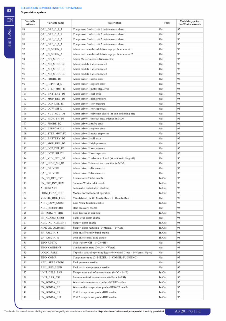
ELECTRONIC CONTROL INSTRUCTION MANUALSupervision system
AS 201÷751 FC
52
EN
GL
ISH
EN
The data in this manual are not binding and may be changed by the manufacturer without notice. Reproduction of this manual, even partial, is strictly prohibited.
88 QAL_ORE_C_1_3 Compressor 3 of circuit 1 maintenance alarm Out 95
89 QAL_ORE_C_2_1 Compressor 1 of circuit 2 maintenance alarm Out 95
90 QAL_ORE_C_2_2 Compressor 2 of circuit 2 maintenance alarm Out 95
91 QAL_ORE_C_2_3 Compressor 3 of circuit 2 maintenance alarm Out 95
92 QAL_N_SBRIN_1 Alarm max. number of defrostings per hour circuit 1 Out 95
93 QAL_N_SBRIN_2 Alarm max. number of defrostings per hour circuit 2 Out 95
94 QAL_NO_MODUL1 Alarm Master module disconnected Out 95
95 QAL_NO_MODUL2 Alarm module 2 disconnected Out 95
96 QAL_NO_MODUL3 Alarm module 3 disconnected Out 95
97 QAL_NO_MODUL4 Alarm module 4 disconnected Out 95
98 QAL_PROBE_D1 Alarm driver 1 probe error Out 95
99 QAL_EEPROM_D1 Alarm driver 1 eeprom error Out 95
100 QAL_STEP_MOT_D1 Alarm driver 1 motor step error Out 95
101 QAL_BATTERY_D1 Alarm driver 1 coil error Out 95
102 QAL_MOP_DEL_D1 Alarm driver 1 high pressure Out 95
103 QAL_LOP_DEL_D1 Alarm driver 1 low pressure Out 95
104 QAL_LOW_SH_D1 Alarm driver 1 low superheat Out 95
105 QAL_VLV_NCL_D1 Alarm driver 1 valve not closed (at unit switching off) Out 95
106 QAL_HIGH_SH_D1 Alarm driver 1 timeout max. suction in MOP Out 95
107 QAL_PROBE_D2 Alarm driver 2 probe error Out 95
108 QAL_EEPROM_D2 Alarm driver 2 eeprom error Out 95
109 QAL_STEP_MOT_D2 Alarm driver 2 motor step error Out 95
110 QAL_BATTERY_D2 Alarm driver 2 coil error Out 95
111 QAL_MOP_DEL_D2 Alarm driver 2 high pressure Out 95
112 QAL_LOP_DEL_D2 Alarm driver 2 low pressure Out 95
113 QAL_LOW_SH_D2 Alarm driver 2 low superheat Out 95
114 QAL_VLV_NCL_D2 Alarm driver 2 valve not closed (at unit switching off) Out 95
115 QAL_HIGH_SH_D2 Alarm driver 2 timeout max. suction in MOP Out 95
116 QAL_DRIVER1 Alarm driver 1 disconnected Out 95
117 QAL_DRIVER2 Alarm driver 2 disconnected Out 95
118 EN_ON_OFF_EXT Remote on/off inlet enable In/Out 95
119 EN_EST_INV_REM Summer/Winter inlet enable In/Out 95
120 AUTOSTART Automatic restart after blackout In/Out 95
121 FORZ_FUNZ_LOC Module forced to local operation In/Out 95
122 VENTIL_DUE_FILE Ventilation type (0=Single-Row - 1=Double-Row) Out 95
123 ABIL_LOW_NOISE Low Noise function enable In/Out 95
124 ABIL_RECUPERO Heat recovery enable Out 95
125 EN_FORZ_V_SBR Fans forcing in dripping In/Out 95
126 EN_ALARM_SERB Tank level alarm enable Out 95
127 ABIL_AL_ALIMENT Supply alarm enable In/Out 95
128 RIPR_AL_ALIMENT Supply alarm restoring (0=Manual - 1=Auto) In/Out 95
129 EN_FASCIA_S Unit on/off weekly band enable In/Out 95
130 EN_FASCIA_G Unit on/off daily band enable In/Out 95
131 TIPO_UNITA Unit type (0=CH - 1=CH+HP) Out 95
132 TIPO_CONDENS Condensation type (0=Air -1=Water) Out 95
133 LOGIC_PARZ Capacity control operating logic (0=Normal Close - 1=Normal Open) Out 95
134 TIPO_COMP Compressor type (0=BITZER - 1=COMER-FU SHENG) Out 95
135 ABIL_SERBATOIO Tank presence enable Out 95
136 ABIL_RES_SERB Tank resistance presence enable Out 95
137 UNIT_CELS_FAR Temperature unit of measurement (0=°C - 1=°F) In/Out 95
138 UNIT_BAR_PSI Pressure unit of measurement (0=Bar - 1=PSI) In/Out 95
139 EN_SONDA_B1 Water inlet temperature probe -BEWIT enable In/Out 95
140 EN_SONDA_B2 Water outlet temperature probe -BEWOT enable In/Out 95
141 EN_SONDA_B3 Coil 1 temperature probe -BD1 enable In/Out 95
142 EN_SONDA_B11 Coil 2 temperature probe -BD2 enable In/Out 95
Variable address Variable name Description Flow Variable type for
LonWorks network
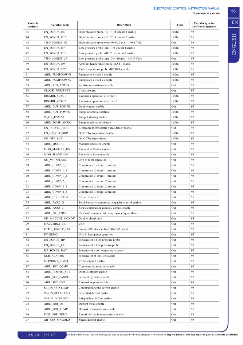
ELECTRONIC CONTROL INSTRUCTION MANUALSupervision system
AS 201÷751 FC
53
EN
GL
ISH
EN
The data in this manual are not binding and may be changed by the manufacturer without notice. Reproduction of this manual, even partial, is strictly prohibited.
143 EN_SONDA_B5 High pressure probe -BHP1 of circuit 1 enable In/Out 95
144 EN_SONDA_B13 High pressure probe -BHP2 of circuit 2 enable In/Out 95
145 TIPO_SONDE_HP High pressure probe type (0=4-20 mA - 1=0-5 Vdc) Out 95
146 EN_SONDA_B7 Low pressure probe -BLP1 of circuit 1 enable In/Out 95
147 EN_SONDA_B15 Low pressure probe -BLP2 of circuit 2 enable In/Out 95
148 TIPO_SONDE_LP Low pressure probe type (0=4-20 mA - 1=0-5 Vdc) Out 95
149 EN_SONDA_B9 Ambient temperature probe -BAT1 enable In/Out 95
150 EN_SONDA_B23 Tank temperature probe -BTOWT enable In/Out 95
151 ABIL_PUMPDOWN1 Pumpdown circuit 1 enable In/Out 95
152 ABIL_PUMPDOWN2 Pumpdown circuit 2 enable In/Out 95
153 ABIL_RES_ANTIG Antifreeze resistance enable Out 95
154 CLOCK_PRESENTE Clock present Out 95
155 DISABIL_CIRC1 Exclusion operation of circuit 1 In/Out 95
156 DISABIL_CIRC2 Exclusion operation of circuit 2 In/Out 95
157 ABIL_DUE_POMPE Double pump enable Out 95
158 ABIL_ROT_POMPE Pump automatic rotation In/Out 95
159 SI_ON_POMPA1 Pump 1 starting enable In/Out 95
160 ABIL_POMP_ANTIG Pump enable as antifreeze In/Out 95
161 EN_DRIVER_VLV Electronic thermostatic valve driver enable Out 95
162 EN_ON_OFF_SUP On/Off by supervisor enable In/Out 95
163 ON_OFF_SUP On/Off by supervisore In/Out 95
164 ABIL_MODULI Modular operation enable Out 95
165 MOD_MASTER_ON The unit is Master module Out 95
166 MOD_SLAVE_ON The unit is Slave module Out 95
167 NO_MODULARE Unit in local operation Out 95
168 ABIL_COMP_1_1 Compressor 1 circuit 1 present Out 95
169 ABIL_COMP_1_2 Compressor 2 circuit 1 present Out 95
170 ABIL_COMP_1_3 Compressor 3 circuit 1 present Out 95
171 ABIL_COMP_2_1 Compressor 1 circuit 2 present Out 95
172 ABIL_COMP_2_2 Compressor 2 circuit 2 present Out 95
173 ABIL_COMP_2_3 Compressor 3 circuit 2 present Out 95
174 ABIL_CIRCUITO2 Circuit 2 present Out 95
175 ABIL_PARZ_G Semi-hermetic compressor capacity control enable Out 95
176 ABIL_PARZ_C Screw compressor capacity control enable Out 95
177 ABIL_PIU_COMP Unit with a number of compressors higher than 1 Out 95
178 OK_MACCH2_MONOV Double-circuit unit Out 95
179 MACCHINA_P57 Unit Out 95
180 ESTIN_ONOFF_LOC Summer/Winter and local On/Off enable Out 95
181 INVERNO Unit in heat pump operation Out 95
182 EN_SONDE_HP Presence of a high pressure probe Out 95
183 EN_SONDE_LP Presence of a low pressure probe Out 95
184 EN_SONDE_BAT Presence of a coil temperature probe Out 95
185 GLB_ALARMS Presence of at least one alarm Out 95
186 SETPOINT_FISSO Fixed setpoint enable Out 95
187 ABIL_SET_COMP Compensated setpoint enable Out 95
188 ABIL_DOPPIO_SET Double setpoint enable Out 95
189 ABIL_SET_FASCE Setpoint by bands enable Out 95
190 ABIL_SET_EXT External setpoint enable Out 95
191 SBRIN_CONTEMP Contemporaneous defrost enable Out 95
192 SBRIN_SEPARATO Separated defrost enable Out 95
193 SBRIN_INDIPEND Independent defrost enable Out 95
194 ABIL_SBR_DT Defrost for dt enable Out 95
195 ABIL_SBR_TEMP Defrost in temperature enable Out 95
196 FINE_SBR_TEMP End of defrost in temperature enable Out 95
197 AB_SBR_SINGOLO Single defrost enable Out 95
Variable address Variable name Description Flow Variable type for
LonWorks network

ELECTRONIC CONTROL INSTRUCTION MANUALSupervision system
AS 201÷751 FC
54
EN
GL
ISH
EN
The data in this manual are not binding and may be changed by the manufacturer without notice. Reproduction of this manual, even partial, is strictly prohibited.
15.6.2 Analogue variables
198 AB_BI_SBR Defrost on double-circuits enable Out 95
Variable address Variable name Description Flow Variable type for
LonWorks network
1 TEMP_IN_ACQ Evaporator water inlet temperature Out 105
2 TEMP_OUT_ACQ Evaporator water outlet temperature Out 105
3 TEMP_OUT_SERB Tank water outlet temperature Out 105
4 TEMP_BATTERIA1 Coil temperature circuit 1 Out 105
5 TEMP_BATTERIA2 Coil temperature circuit 2 Out 105
6 PRESS_COND1 High pressure circuit 1 Out 30
7 PRESS_COND2 High pressure circuit 2 Out 30
8 TEMP_CONV_COND1 High pressure temperature circuit 1 Out 105
9 TEMP_CONV_COND2 High pressure temperature circuit 2 Out 105
10 PRESS_EVAP1 Low pressure circuit 1 Out 30
11 PRESS_ EVAP2 Low pressure circuit 2 Out 30
12 TEMP_CONV_ EVAP1 Low pressure temperature circuit 1 Out 105
13 TEMP_CONV_ EVAP2 Low pressure temperature circuit 2 Out 105
14 TEMP_AMBIENTE Ambient temperature Out 105
15 ACTUAL_SHEAT_D1 Driver 1: overheating value Out 105
16 SUCTION_TEMP_D1 Driver 1: suction temperature Out 105
17 SUCTION_PRESS_D1 Driver 1: evaporator pressure Out 30
18 SATURATION_TEMP_D1
Driver 1: evaporator pressure temperature Out 105
19 ACTUAL_SHEAT_D2 Driver 2: overheating value Out 105
20 SUCTION_TEMP_D2 Driver 2: suction temperature Out 105
21 SUCTION_PRESS_D2 Driver 2: evaporator pressure Out 30
22 SATURATION_TEMP_D2
Driver 2: evaporator pressure temperature Out 105
23 SET_TEMP_CALC Actual temperature setpoint Out 105
24 MIN_SET_T_EST Min. value of summer temperature setpoint In/Out 105
25 MAX_SET_T_EST Max. value of summer temperature setpoint In/Out 105
26 MIN_SET_T_INV Min. value of winter temperature setpoint In/Out 105
27 MAX_SET_T_INV Max. value of winter temperature setpoint In/Out 105
28 SET_TEMP_EST Summer temperature setpoint In/Out 105
29 SEC_SETT_EST Second summer temperature setpoint In/Out 105
30 SET_TEMP_INV Winter temperature setpoint In/Out 105
31 SEC_SETT_INV Second winter temperature setpoint In/Out 105
32 SET_EXT_COMP_E Ambient temperature setpoint for summer compensation In/Out 105
33 DIFF_COMPENSA_E Ambient temperature differential for summer compensation In/Out 105
34 SET_EXT_COMP_I Ambient temperature setpoint for winter compensation In/Out 105
35 DIFF_COMPENSA_I Ambient temperature differential for winter compensation In/Out 105
36 MAX_COMPENSA Max. compensation value In/Out 105
37 SET_FASCIA1_EST Second summer temperature setpoint hourly band 1 In/Out 105
38 SET_FASCIA1_INV Winter temperature setpoint hourly band 1 In/Out 105
39 SET_FASCIA2_EST Second summer temperature setpoint hourly band 2 In/Out 105
40 SET_FASCIA2_INV Winter temperature setpoint hourly band 2 In/Out 105
41 SET_FASCIA3_EST Second summer temperature setpoint hourly band 3 In/Out 105
42 SET_FASCIA3_INV Winter temperature setpoint hourly band 3 In/Out 105
43 SET_FASCIA4_EST Second summer temperature setpoint hourly band 4 In/Out 105
44 SET_FASCIA4_INV Winter temperature setpoint hourly band 4 In/Out 105
45 MAX_SET_EXT Max. value of setpoint by analogue input In/Out 105
46 DIFF_TEMP_EST Summer regulation band In/Out 105
47 DIFF_TEMP_INV Winter regulation band In/Out 105
Variable address Variable name Description Flow Variable type for
LonWorks network
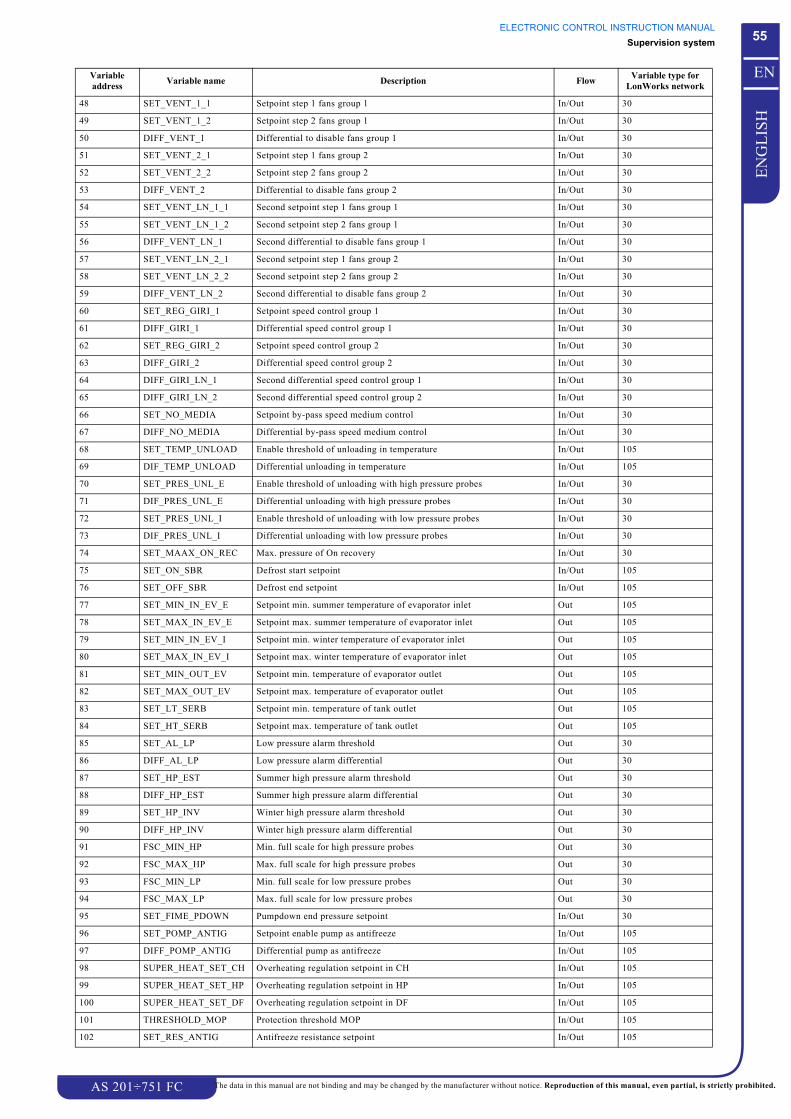
ELECTRONIC CONTROL INSTRUCTION MANUALSupervision system
AS 201÷751 FC
55
EN
GL
ISH
EN
The data in this manual are not binding and may be changed by the manufacturer without notice. Reproduction of this manual, even partial, is strictly prohibited.
48 SET_VENT_1_1 Setpoint step 1 fans group 1 In/Out 30
49 SET_VENT_1_2 Setpoint step 2 fans group 1 In/Out 30
50 DIFF_VENT_1 Differential to disable fans group 1 In/Out 30
51 SET_VENT_2_1 Setpoint step 1 fans group 2 In/Out 30
52 SET_VENT_2_2 Setpoint step 2 fans group 2 In/Out 30
53 DIFF_VENT_2 Differential to disable fans group 2 In/Out 30
54 SET_VENT_LN_1_1 Second setpoint step 1 fans group 1 In/Out 30
55 SET_VENT_LN_1_2 Second setpoint step 2 fans group 1 In/Out 30
56 DIFF_VENT_LN_1 Second differential to disable fans group 1 In/Out 30
57 SET_VENT_LN_2_1 Second setpoint step 1 fans group 2 In/Out 30
58 SET_VENT_LN_2_2 Second setpoint step 2 fans group 2 In/Out 30
59 DIFF_VENT_LN_2 Second differential to disable fans group 2 In/Out 30
60 SET_REG_GIRI_1 Setpoint speed control group 1 In/Out 30
61 DIFF_GIRI_1 Differential speed control group 1 In/Out 30
62 SET_REG_GIRI_2 Setpoint speed control group 2 In/Out 30
63 DIFF_GIRI_2 Differential speed control group 2 In/Out 30
64 DIFF_GIRI_LN_1 Second differential speed control group 1 In/Out 30
65 DIFF_GIRI_LN_2 Second differential speed control group 2 In/Out 30
66 SET_NO_MEDIA Setpoint by-pass speed medium control In/Out 30
67 DIFF_NO_MEDIA Differential by-pass speed medium control In/Out 30
68 SET_TEMP_UNLOAD Enable threshold of unloading in temperature In/Out 105
69 DIF_TEMP_UNLOAD Differential unloading in temperature In/Out 105
70 SET_PRES_UNL_E Enable threshold of unloading with high pressure probes In/Out 30
71 DIF_PRES_UNL_E Differential unloading with high pressure probes In/Out 30
72 SET_PRES_UNL_I Enable threshold of unloading with low pressure probes In/Out 30
73 DIF_PRES_UNL_I Differential unloading with low pressure probes In/Out 30
74 SET_MAAX_ON_REC Max. pressure of On recovery In/Out 30
75 SET_ON_SBR Defrost start setpoint In/Out 105
76 SET_OFF_SBR Defrost end setpoint In/Out 105
77 SET_MIN_IN_EV_E Setpoint min. summer temperature of evaporator inlet Out 105
78 SET_MAX_IN_EV_E Setpoint max. summer temperature of evaporator inlet Out 105
79 SET_MIN_IN_EV_I Setpoint min. winter temperature of evaporator inlet Out 105
80 SET_MAX_IN_EV_I Setpoint max. winter temperature of evaporator inlet Out 105
81 SET_MIN_OUT_EV Setpoint min. temperature of evaporator outlet Out 105
82 SET_MAX_OUT_EV Setpoint max. temperature of evaporator outlet Out 105
83 SET_LT_SERB Setpoint min. temperature of tank outlet Out 105
84 SET_HT_SERB Setpoint max. temperature of tank outlet Out 105
85 SET_AL_LP Low pressure alarm threshold Out 30
86 DIFF_AL_LP Low pressure alarm differential Out 30
87 SET_HP_EST Summer high pressure alarm threshold Out 30
88 DIFF_HP_EST Summer high pressure alarm differential Out 30
89 SET_HP_INV Winter high pressure alarm threshold Out 30
90 DIFF_HP_INV Winter high pressure alarm differential Out 30
91 FSC_MIN_HP Min. full scale for high pressure probes Out 30
92 FSC_MAX_HP Max. full scale for high pressure probes Out 30
93 FSC_MIN_LP Min. full scale for low pressure probes Out 30
94 FSC_MAX_LP Max. full scale for low pressure probes Out 30
95 SET_FIME_PDOWN Pumpdown end pressure setpoint In/Out 30
96 SET_POMP_ANTIG Setpoint enable pump as antifreeze In/Out 105
97 DIFF_POMP_ANTIG Differential pump as antifreeze In/Out 105
98 SUPER_HEAT_SET_CH Overheating regulation setpoint in CH In/Out 105
99 SUPER_HEAT_SET_HP Overheating regulation setpoint in HP In/Out 105
100 SUPER_HEAT_SET_DF Overheating regulation setpoint in DF In/Out 105
101 THRESHOLD_MOP Protection threshold MOP In/Out 105
102 SET_RES_ANTIG Antifreeze resistance setpoint In/Out 105
Variable address Variable name Description Flow Variable type for
LonWorks network
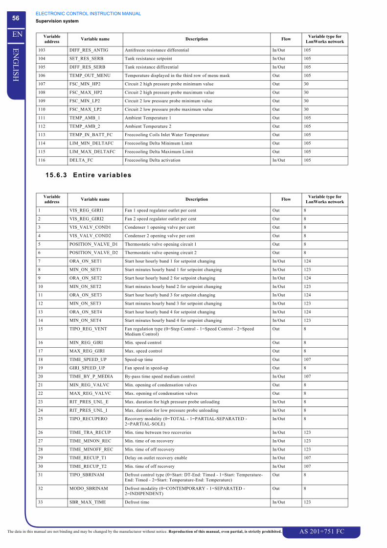
ELECTRONIC CONTROL INSTRUCTION MANUALSupervision system
AS 201÷751 FC
56
EN
GL
ISH
EN
The data in this manual are not binding and may be changed by the manufacturer without notice. Reproduction of this manual, even partial, is strictly prohibited.
15.6.3 Entire variables
103 DIFF_RES_ANTIG Antifreeze resistance differential In/Out 105
104 SET_RES_SERB Tank resistance setpoint In/Out 105
105 DIFF_RES_SERB Tank resistance differential In/Out 105
106 TEMP_OUT_MENU Temperature displayed in the third row of menu mask Out 105
107 FSC_MIN_HP2 Circuit 2 high pressure probe minimum value Out 30
108 FSC_MAX_HP2 Circuit 2 high pressure probe maximum value Out 30
109 FSC_MIN_LP2 Circuit 2 low pressure probe minimum value Out 30
110 FSC_MAX_LP2 Circuit 2 low pressure probe maximum value Out 30
111 TEMP_AMB_1 Ambient Temperature 1 Out 105
112 TEMP_AMB_2 Ambient Temperature 2 Out 105
113 TEMP_IN_BATT_FC Freecooling Coils Inlet Water Temperature Out 105
114 LIM_MIN_DELTAFC Freecooling Delta Minimum Limit Out 105
115 LIM_MAX_DELTAFC Freecooling Delta Maximum Limit Out 105
116 DELTA_FC Freecooling Delta activation In/Out 105
Variable address Variable name Description Flow Variable type for
LonWorks network
1 VIS_REG_GIRI1 Fan 1 speed regulator outlet per cent Out 8
2 VIS_REG_GIRI2 Fan 2 speed regulator outlet per cent Out 8
3 VIS_VALV_COND1 Condenser 1 opening valve per cent Out 8
4 VIS_VALV_COND2 Condenser 2 opening valve per cent Out 8
5 POSITION_VALVE_D1 Thermostatic valve opening circuit 1 Out 8
6 POSITION_VALVE_D2 Thermostatic valve opening circuit 2 Out 8
7 ORA_ON_SET1 Start hour hourly band 1 for setpoint changing In/Out 124
8 MIN_ON_SET1 Start minutes hourly band 1 for setpoint changing In/Out 123
9 ORA_ON_SET2 Start hour hourly band 2 for setpoint changing In/Out 124
10 MIN_ON_SET2 Start minutes hourly band 2 for setpoint changing In/Out 123
11 ORA_ON_SET3 Start hour hourly band 3 for setpoint changing In/Out 124
12 MIN_ON_SET3 Start minutes hourly band 3 for setpoint changing In/Out 123
13 ORA_ON_SET4 Start hour hourly band 4 for setpoint changing In/Out 124
14 MIN_ON_SET4 Start minutes hourly band 4 for setpoint changing In/Out 123
15 TIPO_REG_VENT Fan regulation type (0=Step Control - 1=Speed Control - 2=Speed Medium Control)
Out 8
16 MIN_REG_GIRI Min. speed control Out 8
17 MAX_REG_GIRI Max. speed control Out 8
18 TIME_SPEED_UP Speed-up time Out 107
19 GIRI_SPEED_UP Fan speed in speed-up Out 8
20 TIME_BY_P_MEDIA By-pass time speed medium control In/Out 107
21 MIN_REG_VALVC Min. opening of condensation valves Out 8
22 MAX_REG_VALVC Max. opening of condensation valves Out 8
23 RIT_PRES_UNL_E Max. duration for high pressure probe unloading In/Out 8
24 RIT_PRES_UNL_I Max. duration for low pressure probe unloading In/Out 8
25 TIPO_RECUPERO Recovery modality (0=TOTAL - 1=PARTIAL-SEPARATED - 2=PARTIAL-SOLE)
In/Out 8
26 TIME_TRA_RECUP Min. time between two recoveries In/Out 123
27 TIME_MINON_REC Min. time of on recovery In/Out 123
28 TIME_MINOFF_REC Min. time of off recovery In/Out 123
29 TIME_RECUP_T1 Delay on outlet recovery enable In/Out 107
30 TIME_RECUP_T2 Min. time of off recovery In/Out 107
31 TIPO_SBRINAM Defrost control type (0=Start: DT-End: Timed - 1=Start: Temperature-End: Timed - 2=Start: Temperature-End: Temperature)
Out 8
32 MODO_SBRINAM Defrost modality (0=CONTEMPORARY - 1=SEPARATED - 2=INDIPENDENT)
Out 8
33 SBR_MAX_TIME Defrost time In/Out 123
Variable address Variable name Description Flow Variable type for
LonWorks network

ELECTRONIC CONTROL INSTRUCTION MANUALSupervision system
AS 201÷751 FC
57
EN
GL
ISH
EN
The data in this manual are not binding and may be changed by the manufacturer without notice. Reproduction of this manual, even partial, is strictly prohibited.
34 SBR_DELAY_TIME Defrost control exclusion time In/Out 123
35 SBR_CHECK_TIME Defrost control time In/Out 123
36 SBR_ADD_TIME Defrost additional time In/Out 107
37 TIME_SBR_T1 Compressor off time before defrost In/Out 107
38 TIME_SBR_T2 Compressor off time after defrost In/Out 107
39 VEL_VENT_SBR Fan speed in dripping In/Out 8
40 N_ALL_SBR Max. number defrost per hour In/Out 8
41 RIT_AL_IN_ACQ Delay high/low temperature alarms of evaporator water inlet Out 123
42 RIT_AL_T_SERB Delay high/low temperature alarms of tank water outlet Out 123
43 RIT_LP_PAR Low pressure alarm delay when compressor starts Out 107
44 RIT_LP_REG Low pressure alarm delay with operating compressor Out 107
45 RIT_AL_OLIO Oil level alarm delay Out 107
46 RIT_AL_FLUS_PAR Flow meter alarm when pump starts Out 107
47 RIT_AL_FLUS_REG Flow meter alarm with operating pump Out 107
48 RIT_AL_LIV_SERB Oil level alarm delay Out 107
49 RIT_AL_ALIMENT Supply alarm delay In/Out 107
50 ORA_ON_LOW_N Starting hour of low noise function band In/Out 124
51 MIN_ON_LOW_N Starting minutes of low noise function band In/Out 123
52 ORA_OFF_LOW_N Stopping hour of low noise function band In/Out 124
53 MIN_OFF_LOW_N Stopping minutes of low noise function band In/Out 123
54 ACC_DAY_WEEK Starting day of weekly band (1=Sun - 2=Mon - 3=Tue - 4=Wed - 5=Thu - 6=Fry - 7=Sat)
In/Out 8
55 SPEGN_DAY_WEEK Stopping day of weekly band (1=Sun - 2=Mon - 3=Tue - 4=Wed - 5=Thu - 6=Fry - 7=Sat)
In/Out 8
56 ACC_HOUR Starting hour of daily band In/Out 124
57 ACC_MINUTE Starting minutes of daily band In/Out 123
58 SPEGN_HOUR Stopping hour of daily band In/Out 124
59 SPEGN_MINUTE Stopping minutes of daily band In/Out 123
60 TIPO_MACCHINA Unit type (1=Single-circuit-N°2 Scroll Comp. - 2=Double-circuit-N°4 Scroll Comp. - 3= Double-circuit-N°5 Scroll Comp. - 4= Double-circuit-N°6 Scroll Comp. - 5=Double-circuit-N°2 Semi-hermetic+Cap.Cont.Comp. - 6=Single-circuit-N°1 Screw Compressor)
Out 8
61 RIT_PARZ Disabling delay on compressor capacity control Out 107
62 SONDA_REGOLAZ Regulation probe (0=-BEWIT - 1=-BEWOT - 2=-BTOWT) In/Out 8
63 TIPO_ROTAZ Compressor rotation type (0=None - 1=Circuit - 2=Compressor) In/Out 8
64 TIPO_GAS Gas type for pressure/temperature conversion (0=R22 - 1=R134C - 2=R404A - 3=R407C - 4=R410A - 5=R507C - 6=R209 - 7=R600 - 8=R600A - 9=R717 - 10=R744)
In/Out 8
65 TIME_MAX_PDOWN Max. pump-down time In/Out 107
66 NUM_MODULI Number of modules for modular operation Out 8
67 SONDA_REG_MOD Regulation probe for modular operation (0=-BEWIT - 1=-BEWOT - 2=-BTOWT)
Out 8
68 PESO_MODULO1 Weight module 1 for the calculation of temperature regulation Out 8
69 PESO_MODULO2 Weight module 2 for the calculation of temperature regulation Out 8
70 PESO_MODULO3 Weight module 3 for the calculation of temperature regulation Out 8
71 PESO_MODULO4 Weight module 4 for the calculation of temperature regulation Out 8
72 RIT_ATTIV_GRAD Delay between starts out of neutral zone In/Out 107
73 RIT_DISAT_GRAD Delay between stops out of neutral zone In/Out 107
74 RIT_AT_INT_GRAD Delay between starts in of neutral zone In/Out 123
75 TEMPO_INTEGRA PI control integration time In/Out 107
76 RIT_ON_COMP Delay on compressor start at unit start In/Out 107
77 T_MIN_OFF Min. time for compressor stop Out 107
78 T_MIN_ON Min. time for compressor start Out 107
79 T_STESS_COMP Time between starts of the same compressor Out 107
80 T_TRA_COMP Time between starts of different compressors Out 107
81 TIME_PARTW Partwinding time Out 8
82 RIT_AL_PARTW Partwinding alarm delay Out 107
83 TIME_VALV_INT Intermittent valve time Out 107
Variable address Variable name Description Flow Variable type for
LonWorks network
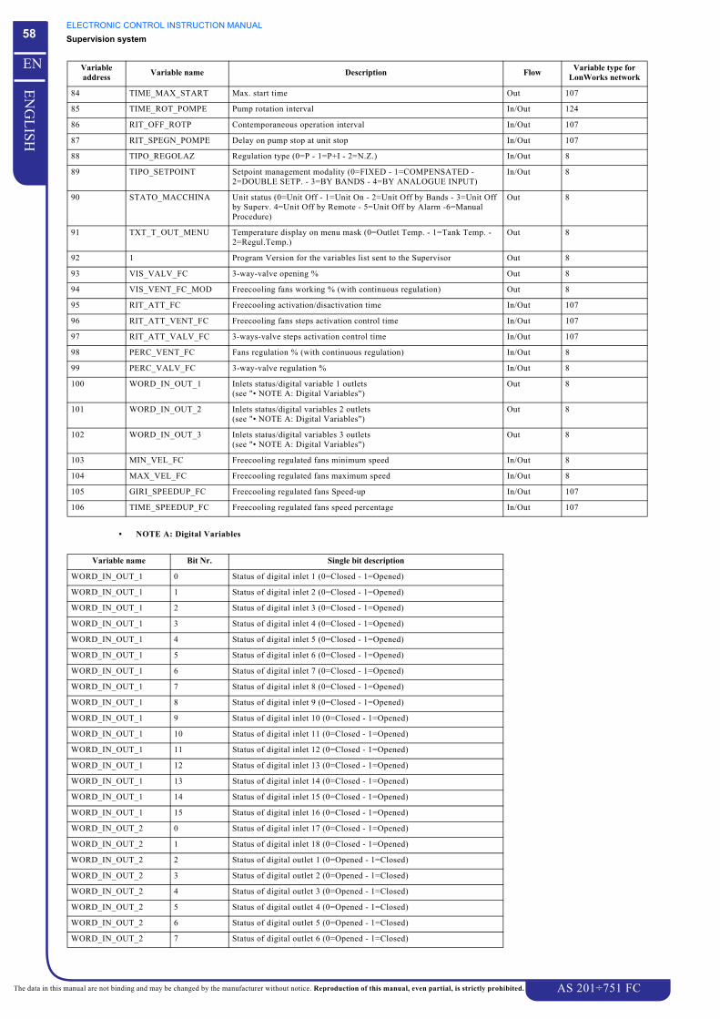
ELECTRONIC CONTROL INSTRUCTION MANUALSupervision system
AS 201÷751 FC
58
EN
GL
ISH
EN
The data in this manual are not binding and may be changed by the manufacturer without notice. Reproduction of this manual, even partial, is strictly prohibited.
• NOTE A: Digital Variables
84 TIME_MAX_START Max. start time Out 107
85 TIME_ROT_POMPE Pump rotation interval In/Out 124
86 RIT_OFF_ROTP Contemporaneous operation interval In/Out 107
87 RIT_SPEGN_POMPE Delay on pump stop at unit stop In/Out 107
88 TIPO_REGOLAZ Regulation type (0=P - 1=P+I - 2=N.Z.) In/Out 8
89 TIPO_SETPOINT Setpoint management modality (0=FIXED - 1=COMPENSATED - 2=DOUBLE SETP. - 3=BY BANDS - 4=BY ANALOGUE INPUT)
In/Out 8
90 STATO_MACCHINA Unit status (0=Unit Off - 1=Unit On - 2=Unit Off by Bands - 3=Unit Off by Superv. 4=Unit Off by Remote - 5=Unit Off by Alarm -6=Manual Procedure)
Out 8
91 TXT_T_OUT_MENU Temperature display on menu mask (0=Outlet Temp. - 1=Tank Temp. - 2=Regul.Temp.)
Out 8
92 1 Program Version for the variables list sent to the Supervisor Out 8
93 VIS_VALV_FC 3-way-valve opening % Out 8
94 VIS_VENT_FC_MOD Freecooling fans working % (with continuous regulation) Out 8
95 RIT_ATT_FC Freecooling activation/disactivation time In/Out 107
96 RIT_ATT_VENT_FC Freecooling fans steps activation control time In/Out 107
97 RIT_ATT_VALV_FC 3-ways-valve steps activation control time In/Out 107
98 PERC_VENT_FC Fans regulation % (with continuous regulation) In/Out 8
99 PERC_VALV_FC 3-way-valve regulation % In/Out 8
100 WORD_IN_OUT_1 Inlets status/digital variable 1 outlets(see "• NOTE A: Digital Variables")
Out 8
101 WORD_IN_OUT_2 Inlets status/digital variables 2 outlets(see "• NOTE A: Digital Variables")
Out 8
102 WORD_IN_OUT_3 Inlets status/digital variables 3 outlets(see "• NOTE A: Digital Variables")
Out 8
103 MIN_VEL_FC Freecooling regulated fans minimum speed In/Out 8
104 MAX_VEL_FC Freecooling regulated fans maximum speed In/Out 8
105 GIRI_SPEEDUP_FC Freecooling regulated fans Speed-up In/Out 107
106 TIME_SPEEDUP_FC Freecooling regulated fans speed percentage In/Out 107
Variable name Bit Nr. Single bit description
WORD_IN_OUT_1 0 Status of digital inlet 1 (0=Closed - 1=Opened)
WORD_IN_OUT_1 1 Status of digital inlet 2 (0=Closed - 1=Opened)
WORD_IN_OUT_1 2 Status of digital inlet 3 (0=Closed - 1=Opened)
WORD_IN_OUT_1 3 Status of digital inlet 4 (0=Closed - 1=Opened)
WORD_IN_OUT_1 4 Status of digital inlet 5 (0=Closed - 1=Opened)
WORD_IN_OUT_1 5 Status of digital inlet 6 (0=Closed - 1=Opened)
WORD_IN_OUT_1 6 Status of digital inlet 7 (0=Closed - 1=Opened)
WORD_IN_OUT_1 7 Status of digital inlet 8 (0=Closed - 1=Opened)
WORD_IN_OUT_1 8 Status of digital inlet 9 (0=Closed - 1=Opened)
WORD_IN_OUT_1 9 Status of digital inlet 10 (0=Closed - 1=Opened)
WORD_IN_OUT_1 10 Status of digital inlet 11 (0=Closed - 1=Opened)
WORD_IN_OUT_1 11 Status of digital inlet 12 (0=Closed - 1=Opened)
WORD_IN_OUT_1 12 Status of digital inlet 13 (0=Closed - 1=Opened)
WORD_IN_OUT_1 13 Status of digital inlet 14 (0=Closed - 1=Opened)
WORD_IN_OUT_1 14 Status of digital inlet 15 (0=Closed - 1=Opened)
WORD_IN_OUT_1 15 Status of digital inlet 16 (0=Closed - 1=Opened)
WORD_IN_OUT_2 0 Status of digital inlet 17 (0=Closed - 1=Opened)
WORD_IN_OUT_2 1 Status of digital inlet 18 (0=Closed - 1=Opened)
WORD_IN_OUT_2 2 Status of digital outlet 1 (0=Opened - 1=Closed)
WORD_IN_OUT_2 3 Status of digital outlet 2 (0=Opened - 1=Closed)
WORD_IN_OUT_2 4 Status of digital outlet 3 (0=Opened - 1=Closed)
WORD_IN_OUT_2 5 Status of digital outlet 4 (0=Opened - 1=Closed)
WORD_IN_OUT_2 6 Status of digital outlet 5 (0=Opened - 1=Closed)
WORD_IN_OUT_2 7 Status of digital outlet 6 (0=Opened - 1=Closed)
Variable address Variable name Description Flow Variable type for
LonWorks network
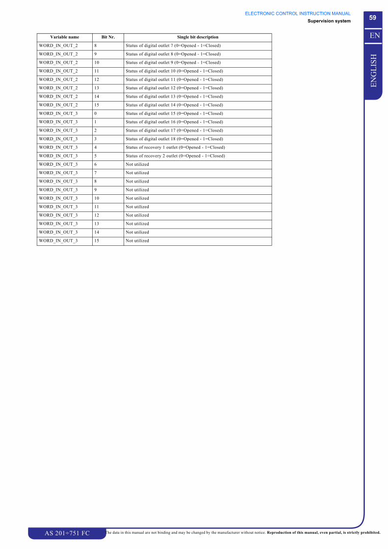
ELECTRONIC CONTROL INSTRUCTION MANUALSupervision system
AS 201÷751 FC
59
EN
GL
ISH
EN
The data in this manual are not binding and may be changed by the manufacturer without notice. Reproduction of this manual, even partial, is strictly prohibited.
WORD_IN_OUT_2 8 Status of digital outlet 7 (0=Opened - 1=Closed)
WORD_IN_OUT_2 9 Status of digital outlet 8 (0=Opened - 1=Closed)
WORD_IN_OUT_2 10 Status of digital outlet 9 (0=Opened - 1=Closed)
WORD_IN_OUT_2 11 Status of digital outlet 10 (0=Opened - 1=Closed)
WORD_IN_OUT_2 12 Status of digital outlet 11 (0=Opened - 1=Closed)
WORD_IN_OUT_2 13 Status of digital outlet 12 (0=Opened - 1=Closed)
WORD_IN_OUT_2 14 Status of digital outlet 13 (0=Opened - 1=Closed)
WORD_IN_OUT_2 15 Status of digital outlet 14 (0=Opened - 1=Closed)
WORD_IN_OUT_3 0 Status of digital outlet 15 (0=Opened - 1=Closed)
WORD_IN_OUT_3 1 Status of digital outlet 16 (0=Opened - 1=Closed)
WORD_IN_OUT_3 2 Status of digital outlet 17 (0=Opened - 1=Closed)
WORD_IN_OUT_3 3 Status of digital outlet 18 (0=Opened - 1=Closed)
WORD_IN_OUT_3 4 Status of recovery 1 outlet (0=Opened - 1=Closed)
WORD_IN_OUT_3 5 Status of recovery 2 outlet (0=Opened - 1=Closed)
WORD_IN_OUT_3 6 Not utilized
WORD_IN_OUT_3 7 Not utilized
WORD_IN_OUT_3 8 Not utilized
WORD_IN_OUT_3 9 Not utilized
WORD_IN_OUT_3 10 Not utilized
WORD_IN_OUT_3 11 Not utilized
WORD_IN_OUT_3 12 Not utilized
WORD_IN_OUT_3 13 Not utilized
WORD_IN_OUT_3 14 Not utilized
WORD_IN_OUT_3 15 Not utilized
Variable name Bit Nr. Single bit description

ELECTRONIC CONTROL INSTRUCTION MANUALMasks no password required
AS 201÷751 FC
60
EN
GL
ISH
EN
The data in this manual are not binding and may be changed by the manufacturer without notice. Reproduction of this manual, even partial, is strictly prohibited.
CHAPTER 16
MASKS NO PASSWORD REQUIRED
DANGERThe wrong pCO programming can cause big damages to the unit;if there is any doubt please call an authorised service centre.
NOTEFor information about the parameter setting please consult Chapter 20 “Setting Tables“.
ATTENTIONThe displaying of some masks depends on the settings of other masks and also on the unit configuration, decided during design phase.
1 6 . 1 M e n u• During normal operation, press f or g button on the terminals
Ref. Mask (*)
* R: Read only maskW: Read and write mask.
Range Notes
A1 R
This is the main mask, which displays, in the second row, the values measured by the temperature probe of evaporator water inlet (-BEWIT probe) and, in the third row, of evaporator water outlet (-BEWOT probe).The first row of the display will show the current time and date.The last row will show the unit status (on, off, manual mode, off by remote control, off by time bands control).In the event of abnormal operation, the flashing message “
” will be displayed in the last row.
A2 R Unit specifications, program version.Bios and Boot versions.
A3 R
Modem status.
.!1!! !!! #!$.1.,12 3!
!" #$%

ELECTRONIC CONTROL INSTRUCTION MANUALMasks no password required
AS 201÷751 FC
61
EN
GL
ISH
EN
The data in this manual are not binding and may be changed by the manufacturer without notice. Reproduction of this manual, even partial, is strictly prohibited.
1 6 . 2 F r e e M e n uPress and release l button on the terminal to access the loop mask (Free Menu); to modify a parameter see Chapter 5 “How to modify a parameter in “Free
Menu”“
Inside the masks of a loop (see mask from Ref. C1 to Ref. C8) it is possible to return to Free Menu (see Ref. B1), simply pressing once k button;
press it twice to return to the main mask (Ref. A1 - see paragraph "16.1 Menu").
Ref. Mask (*)
* R: Read only maskW: Read and write mask.
Range Notes
B1 R When this mask has been reached, to enter the parameters follow the indications of the following diagram:
SETPOINT
Ref. Mask (*) Range Notes
C1 R Identifies the actual unit operation setpoint.
C2 W see Ref. V2 step: 00.1
÷
Use this mask to fix the setpoint and the second setpoint, if enabled.For further information see Chapter 8 “Fixed setpoint“ and Chapter 8 “Double setpoint“.
C3 W ÷
÷step: 00.1
Use this mask to fix the setpoint of external temperature used to calculate the compensated setpoint.For further information see Chapter 8 “Compensated setpoint“.
C4 W ÷step: 00.1
Use this mask to fix the max. compensation value.For further information see Chapter 8 “Compensated setpoint“.
C5 W ÷ ÷
see Ref. V2step: 00.1
Use this mask to set the starting hour and the setpoint of the first band.For further information see Chapter 8 “Adjustable setpoint by daily bands“.
C6 W ÷ ÷
see Ref. V2step: 00.1
Use this mask to set the starting hour and the setpoint of the second band.For further information see Chapter 8 “Adjustable setpoint by daily bands“.
h
f
f
h
f
h
D1
C1
E1
!"#$! !"#

ELECTRONIC CONTROL INSTRUCTION MANUALMasks no password required
AS 201÷751 FC
62
EN
GL
ISH
EN
The data in this manual are not binding and may be changed by the manufacturer without notice. Reproduction of this manual, even partial, is strictly prohibited.
C7 W ÷ ÷
see Ref. V2step: 00.1
Use this mask to set the starting hour and the setpoint of the third band.For further information see Chapter 8 “Adjustable setpoint by daily bands“.
C8 W ÷ ÷
see Ref. V2step: 00.1
Use this mask to set the starting hour and the setpoint of the fourth band.For further information see Chapter 8 “Adjustable setpoint by daily bands“.
* R: Read only maskW: Read and write mask.
USER
Ref. Mask (*)
* R: Read only maskW: Read and write mask.
Range Notes
D1 W
÷
÷step: 00.1
Use this mask to set the regulation temperature band (Differential).
D2 W ÷÷
Use this mask to enable the remote ON/OFF of pCO (digital input Nr. 1).
D3 W ÷ An option of the electronic control allows to restart automatically the unit after a blackout or after any power failure.The automatic restart is possible only if the unit, at the power failure, was already ON.For further information consult paragraph "4.2 Automatic restart"
D4 W It allows to select the desired language for the masks.For further information consult paragraph "5.3 How to modify the language"
I/O
Ref. Mask (*) Range Notes
E1 R Values measured by temperature probes of evaporator water inlet and outlet and tank water outlet.This mask will be displayed only if -BEWIT, -BEWOT and -BTOWT probes have been previously enabled.For further information see Chapter 2 “Pressure and temperature transducers“
E2 R Value measured by temperature probe of condensing coil of circuit 1.This mask will be displayed only if -BD1 and -BD2 probes have been previously enabled.For further information see Chapter 2 “Pressure and temperature transducers“
E3 R Value measured by high pressure transducer of circuit 1.This mask will be displayed only if -BHP1 probe has been previously enabled.For further information see Chapter 2 “Pressure and temperature transducers“
Ref. Mask (*) Range Notes
! "# $ ! "# $
# % !"#
# % !

ELECTRONIC CONTROL INSTRUCTION MANUALMasks no password required
AS 201÷751 FC
63
EN
GL
ISH
EN
The data in this manual are not binding and may be changed by the manufacturer without notice. Reproduction of this manual, even partial, is strictly prohibited.
E4 R Values measured by high pressure transducers of circuits 1, expressed in °C.This mask will be displayed only if -BHP1 probe has been previously enabled.For further information see Chapter 2 “Pressure and temperature transducers“
E5 R Values measured by low pressure transducers of circuits 1, expressed in bar.This mask will be displayed only if -BLP1 probe has been previously enabled.For further information see Chapter 2 “Pressure and temperature transducers“
E6 R Values measured by low pressure transducers of circuits 1, expressed in °C.This mask will be displayed only if -BLP1 probe has been previously enabled.For further information see Chapter 2 “Pressure and temperature transducers“
E7 R The values detected by the ambient probe 1 and 2 are measured in °C.This mask will be displayed only if -BAT1 and -BAT2 probes have been previously enabled.For further information see Capitolo 2 “Trasduttori e Sonde“.
E8 The values detected by the free-cooling temperature probe are measured in °C.This mask will be displayed only if -BFCIT probe has been previously enabled.For further information see Capitolo 2 “Trasduttori e Sonde“.
E9 R This mask shows the status of digital inputs of the board:
= close: connected to 24 Vac (normal status);
= open: not connected to 24 Vac (alarm status).
E10 R This mask shows the status of digital outputs of the board:
= de-energized outlet;
= energized outlet.
E11 R This mask shows the status of heat recovery valves of circuit 1.
E12 R This mask shows the percentage of fan speed if they are controlled by a speed regulator.For further information see Chapter 11 “Fans operation management“.
E13 R This mask displays the free-cooling fans speed if they are managed by the speed regulator.For further information see Capitolo 11 “Ventilatori Free Cooling“.
E14 R This mask allows to enter the loop about the Driver status of electronic thermostatic valves.It is sufficient to press twice h button to display the following masks.
* R: Read only maskW: Read and write mask.
Ref. Mask (*) Range Notes
# % !"#
# % !
# % !"#
)%!!!%(+ 444444 444444 444444
)%!!!%(+ 444444 444444 444444
0
! !
!

ELECTRONIC CONTROL INSTRUCTION MANUALMasks requiring a password
AS 201÷751 FC
64
EN
GL
ISH
EN
The data in this manual are not binding and may be changed by the manufacturer without notice. Reproduction of this manual, even partial, is strictly prohibited.
CHAPTER 17
MASKS REQUIRING A PASSWORD1 7 . 1 M e n u w i t h p a s s w o r d
DANGERThe wrong pCO programming can cause big damages to the unit;if there is any doubt please call an authorised service centre.
NOTEFor information about the parameter setting please consult Chapter 20 “Setting Tables“.
Inside this Loop are the masks which permit to set the fundamental parameters for the correct unit operation.
The modification of these parameters is necessary only in the following cases:
• When a new pCO board is installed.• When for any reason, as fluctuations on the electrical power supply, any parameter has incorrect values.
ATTENTIONThe modifying of these parameters must be carried out by specialized personnel only, therefore it is necessary to call an authorized servicecentre.
The access to this menu can be carried out following the procedure here indicated; to modify the parameters follow the indication of Chapter 5 “How to modify
a parameter of “Password Menu”“.
• keep l button pressed for 5 seconds at least, then release it;
• insert the password using f or g buttons, then confirm it pressing h button.
ATTENTIONThe number of mask which is possible to access depends on the password (user, maintenance or manufacturer).USER password is: 00805.SERVICE password is: 01234.
ATTENTIONThe displaying of some masks depends on the settings of other masks and also on the unit configuration, decided during design phase.
Ref. Mask (*) Range Notes
F1 W ÷ After inserting the password press h button.
If the password is not correct “ ” will appear, it is necessary to insert the password again.If the password is correct, it is possible to access the following mask “Password Menu” (Ref. F2).

ELECTRONIC CONTROL INSTRUCTION MANUALMasks requiring a password
AS 201÷751 FC
65
EN
GL
ISH
EN
The data in this manual are not binding and may be changed by the manufacturer without notice. Reproduction of this manual, even partial, is strictly prohibited.
F2 R When this mask has been reached, to enter the parameters follow the indications of the diagram here below:
* R: Read only maskW: Read and write mask.
Ref. Mask (*) Range Notes
h
f
f
h
f
f
h
G1
H1
I1
J1h
f
f
h K1
L1h
f
f
h M1
N1h
f
f
hO1
h
f
f
hQ1
Q1h
f
f
hR1
S1h
f
hU1
P1
f
V1h
f
hW1

ELECTRONIC CONTROL INSTRUCTION MANUALMasks requiring a password
AS 201÷751 FC
66
EN
GL
ISH
EN
The data in this manual are not binding and may be changed by the manufacturer without notice. Reproduction of this manual, even partial, is strictly prohibited.
Inside the masks of a loop (see masks “UNIT CONFIGURATION”) it is possible to return to Password Menu (see Ref. F2), simply pressing once k
button;
press it twice to return to the main mask (Ref. A1 - see paragraph "16.1 Menu").
UNIT CONFIGURATION
Ref. Mask (*) Range Notes
G3 W -
-
This mask is used to set the regulation probe for water temperature regulation during LOCAL modality operation.For further information consult Chapter 7 “Temperature regulation management“.Furthermore, it is possible to enable the compressor rotation.For further information consult Chapter 10 “Compressors sequencing procedure“.
G5 W ° ÷ °
÷
The software can convert the default unit of measurement to the Anglo-Saxon unit of measurement (°C, °F, bar, PSI).The unit of measurement could be set (as bar or as psi) only if the pressure probes have been previously enabled.After modifying the unit of measurement, the default values for temperature and/or pressure settings will be installed again.This operation must be carried out before modifying eventual settings which could be lost.
G6 W ÷
÷
It allows to enable the probes which measure the evaporator water inlet temperature (-BEWIT) and the evaporator water outlet temperature (-BEWOT).For further information consult Chapter 2 “Function of transducers and of probes“.
G7 W ÷
÷
It allows to enable the high pressure transducer of circuit 1 (-BHP1).For further information consult Chapter 2 “Function of transducers and of probes“.
G8 W ÷
÷step:000.1
Use this mask to fix the operating range of high pressure transducers.Furthermore, it is possible to fix the type of return signal of the transducer.
G9 W ÷
÷
It allows to enable the low pressure transducer of circuit 1 (-BLP1).For further information consult Chapter 2 “Function of transducers and of probes“.
G10 W ÷ It allows to enable the tank water outlet temperature probe (-BTOWT).For further information consult Capitolo 2 “La funzione dei trasduttori e delle sonde“.
G11 W ÷
÷
It allows to enable the ambient temperature probes (-BAT1) and (-BAT2).For further information consult Capitolo 2 “La funzione dei trasduttori e delle sonde“.
G12 W ÷
÷
It allows to enable the free-cooling coils inlet temperature probes (-BFCIT).For further information consult Capitolo 2 “La funzione dei trasduttori e delle sonde“.
BEWIT
1& "#
# %),%+
!
# %)*%+
)151+
" #"
"#"

ELECTRONIC CONTROL INSTRUCTION MANUALMasks requiring a password
AS 201÷751 FC
67
EN
GL
ISH
EN
The data in this manual are not binding and may be changed by the manufacturer without notice. Reproduction of this manual, even partial, is strictly prohibited.
G13 W ÷
÷
Use this mask to enable the pumpdown procedure for circuit 1 .For further information consult Chapter 10 “Compressors Pump-Down procedure (only AS 351÷751 FC units)“.
G14 W ÷
÷step: 000.1
Use this mask to set the max. time for pump-down and the low pressure threshold which fixes the pump-down end.If after max. time the low pressure threshold is not reached, the compressor stops and an alarm which blocks the circuit is activated (see Ref. AM20).This mask will be displayed only when the pump-down procedure has been enabled (see Ref. G13) and if the low pressure probes have
been previously enabled (see Ref. G9).For further information consult Chapter 10 “Compressors Pump-Down procedure (only AS 351÷751 FC units)“
* R: Read only maskW: Read and write mask.
MODULARITY
DRIVER
Ref. Mask (*)
* R: Read only maskW: Read and write mask.
Range Notes
I5 W ÷÷
step: 0.1
Use this mask to set the min. and max. value of evaporator pressure probe.
I6 W ÷step: 0.1
÷step: 1
÷step: 0.1
In this mask it is possible to insert the proportional, integral and derivative values of PID.
I7 W ÷step: 0.1
÷step: 0.1
Use this mask to fix the setpoint for overheating regulation and the temperature interval during which this regulation is not considered (Dead Area).
I8 W ÷step: 0.1
÷step: 0.1
Use this parameter to fix the tripping threshold of low pressure protection. Under this value it starts the integral type regulation with an adjustable constant, in order to restore and maintain the temperature over the preset value.Furthermore, it is possible to fix the integration time.
I12 W ÷
step: 0.1
Use this mask to fix the value used to enable the suction high pressure alarm (MOP).
I13 W ÷÷
step: 0.1
Use this mask to fix the delay in low and high overheating alarms.
Ref. Mask (*) Range Notes
# %
-& !"#
!
!"#

ELECTRONIC CONTROL INSTRUCTION MANUALMasks requiring a password
AS 201÷751 FC
68
EN
GL
ISH
EN
The data in this manual are not binding and may be changed by the manufacturer without notice. Reproduction of this manual, even partial, is strictly prohibited.
HOURS WORKED
Ref. Mask (*) Range Notes
J1 R Unit working hours (time during which the board is activated).
J2 R Total number of working hours and number of startings of pump 1.
J3 R Total number of working hours and number of startings of pump 2.
J4 R Total number of working hours and number of startings of compressor 1 of the first circuit.For further information consult paragraph "10.2 Working hours and startings of compressors and of the unit".
J5 R Total number of working hours and number of startings of compressor 2 of the first circuit.For further information consult paragraph "10.2 Working hours and startings of compressors and of the unit".
J6 W ÷÷÷
step: 1
Use this mask to select the working hour thresholds for unit, pump and compressors.When this threshold is exceeded, the appropriate maintenance alarm will appear.For further information consult paragraph "10.2 Working hours and startings of compressors and of the unit" and paragraph "18.3 Alarms masks".
J7 W ÷ Use this mask to reset the contactors of working hours.To reset, set the interested parameter to “ ” and confirm by pressing
g button.For further information consult paragraph "10.2 Working hours and startings of compressors and of the unit" and paragraph "18.3 Alarms masks".
J8 W ÷÷
Use this mask to reset the contactors of working hours and of startings of pump 1.To reset, set the interested parameter to “ ” and confirm by pressing
g button.
J9 W ÷÷
Use this mask to reset the contactors of working hours and of startings of pump 2.To reset, set the interested parameter to “ ” and confirm by pressing
g button.
J10 W ÷÷
Use this mask to reset the contactors of working hours and of startings of compressor 1 of circuit 1.To reset, set the interested parameter to “ ” and confirm by pressing
g button.
J11 W ÷÷
Use this mask to reset the contactors of working hours and of startings of compressor 2 of circuit 1.To reset, set the interested parameter to “ ” and confirm by pressing
g button.
& %
& '
#!%#& %
#!%#& '
& #&

ELECTRONIC CONTROL INSTRUCTION MANUALMasks requiring a password
AS 201÷751 FC
69
EN
GL
ISH
EN
The data in this manual are not binding and may be changed by the manufacturer without notice. Reproduction of this manual, even partial, is strictly prohibited.
* R: Read only maskW: Read and write mask.
MANUAL OPERATION
Ref. Mask (*)
* R: Read only maskW: Read and write mask.
Range Notes
K1 W ÷ Use this mask to enable the manual procedure.The selection of the manual procedure forces the OFF status of the unit.After enabling the manual procedure the masks from Ref. K2 to
Ref. K6 will appear.For further information consult Chapter 13 “Manual procedure“.
K2 W ÷÷
This mask allows to start manually pump 1 or pump 2.
K3 W ÷÷÷
Use this mask to manually start the compressor 1 - 2 or 3 of the first circuit when the manual procedure is enabled (Ref. K1) in order to verify its operation.It is first necessary to turn ON the pump (Ref. K2).
K4 W ÷÷
This mask will be displayed only after the manual procedure has been enabled (Ref. K1).Use this mask to verify the fan two-step operation of group 1, when manual mode is enabled.
K5 W ÷÷
This mask will be displayed only after the manual procedure has been enabled (Ref. K1)Use this mask to regulate the fan speed when the unit is in manual mode.
K6 W ÷÷
This mask will be displayed only after the manual procedure has been enabled (Ref. K1).Use this mask to verify the operation of antifreeze resistance or tank resistance.
K7 W+R
÷÷
This mask will be displayed only after the manual procedure has been enabled (Ref. K1).Use this mask to manually regulate the opening of the electronic thermostatic valve of circuit 1.The parameter “ ” is read only and displays the actual opening step of the valve.
K8 R ÷ Not used mask.
K9 W ÷÷
This mask will be displayed only if the manual procedure has been previously enabled Ref. K1.Use this mask to check the operation of the fans two steps, if the manual procedure has been enabled.
K10 W ÷÷
This mask will be displayed only if the manual procedure has been previously enabled Ref. K1. .In the upper part of the display:it is utilized to manage the opening percentage of the Free-Cooling fans 3-way-valve, if the manual procedure has been previously enabled.In the lower part:it is utilized to regulate the Free-Cooling fans speed, if the manual procedure has been previously enabled.
& % & '
-& %
# %' 0# ' 0
!" #$ #

ELECTRONIC CONTROL INSTRUCTION MANUALMasks requiring a password
AS 201÷751 FC
70
EN
GL
ISH
EN
The data in this manual are not binding and may be changed by the manufacturer without notice. Reproduction of this manual, even partial, is strictly prohibited.
COMPRESSORS
Ref. Mask (*)
* R: Read only maskW: Read and write mask.
Range Notes
L1 W ÷step: 1
This mask will be displayed only if the temperature regulation is set to Neutral Zone (Ref. V1).It allows to set the compressor starting delays when the temperature measured by temperature regulation probe is out of the Neutral Zone limits (see "7.1 Water temperature regulation for conditioning use in chiller modality").
L2 W ÷step: 1
This mask will be displayed only if the temperature regulation is set to Neutral Zone (Ref. V1).It allows to set the compressor stopping delays when the temperature measured by temperature regulation probe is out of the Neutral Zone limits (see "7.1 Water temperature regulation for conditioning use in chiller modality").
L3 W ÷1step: 1
This mask will be displayed only if the temperature regulation is set to Neutral Zone (Ref. V1).It allows to set the compressors starting delays when the temperature measured by temperature regulation probe is within the Neutral Zone limits (see "7.1 Water temperature regulation for conditioning use in chiller modality").
L4 W ÷step: 1
This mask will be displayed only if the temperature regulation is set to P+I (Ref. V1).It allows to fix the integration time.
L4 W ÷step: 1
When pCO is switched on or commuted from OFF to ON, the compressors are started after the delay time here set.
PUMPS
Ref. Mask (*) Range Notes
M2 W ÷ This mask is displayed only if the double pump is enabled.Use this mask to enable the automatic rotation of pumps.
M3 W ÷÷
step: 1
This mask is displayed only if the double pump is enabled and if the automatic rotation of pumps is enabled (Ref. M2).It allows to fix the rotation interval time, after this time a pump stops and the other pump starts.Furthermore, it is possible to fix an interval time, before the rotation, during which both the pumps operate.
M4 W ÷step: 1
This mask is displayed only if the double pump is enabled and if the automatic rotation of pumps is enabled (Ref. M2).It allows to fix a delay time on pump stopping from unit stopping.For further information consult Chapter 12 “Single or double pump operation management“
M5 W ÷÷
This mask is displayed only if the double pump is enabled and if the automatic rotation of pumps is enabled (Ref. M2).Use this mask to enable the start of pump 1 or 2.
& % & '

ELECTRONIC CONTROL INSTRUCTION MANUALMasks requiring a password
AS 201÷751 FC
71
EN
GL
ISH
EN
The data in this manual are not binding and may be changed by the manufacturer without notice. Reproduction of this manual, even partial, is strictly prohibited.
M6 W ÷step: 1
Use this mask to fix the time for the contemporaneous operation of both the pumps from pump operation changing.
M7 W ÷÷÷
step: 00.1
Use this mask to enable the pump in antifreeze function.The pump starts under the setpoint value and stops (if necessary) when setpoint + differential is exceeded.
* R: Read only maskW: Read and write mask.
FANS
Ref. Mask (*) Range Notes
N2 W ÷ This mask allows to enable “Low Noise” function (see paragraph "11.2 Nightly operation")
N3 W ÷÷
step: 000.1
It allows to fix the setpoint for each step of fan tripping of group 1.For further information consult Chapter 11 “Fans operation management“.
N4 W ÷step: 000.1
It allows to fix the differential of fans of group 1.For further information consult Chapter 11 “Fans operation management“.
N5 W ÷÷
step: 000.1
This mask will be displayed only if “ ” function (Ref. N2) has been enabled.It allows to fix the second setpoint for each step of fan tripping of group 1.
N6 W ÷step: 000.1
This mask will be displayed only if “ ” function (Ref. N2) has been enabled.It allows to fix the second differential of fans of group 1.
N9 W ÷÷
step: 000.1
Use this mask to set the setpoint and the differential for fan speed regulation of group 1.For further information consult Chapter 11 “Fans operation management“.
N10 W ÷÷
step: 000.1
This mask will be displayed only if “ ” function (Ref. N2) has been enabledUse this mask to set the second differential for fan speed regulation.
N11 W ÷step: 1
Use this mask to fix the time for operation in “ ”,
then it will pass to “ ”.
Ref. Mask (*) Range Notes
!" -& !"#$! !"#
* + ( , +
-& % !-& ' !
% -& % !-& ' !
%
-& # -& !$! !
-& # %
-& . # &' ! (

ELECTRONIC CONTROL INSTRUCTION MANUALMasks requiring a password
AS 201÷751 FC
72
EN
GL
ISH
EN
The data in this manual are not binding and may be changed by the manufacturer without notice. Reproduction of this manual, even partial, is strictly prohibited.
N12 W ÷÷
step: 000.1
Use this mask to set the setpoint and the differential for fan speed regulation.For further information consult Chapter 11 “Fans operation management“.
* R: Read only maskW: Read and write mask.
UNLOADING
Ref. Mask (*)
* R: Read only maskW: Read and write mask.
Range Notes
O1 W ÷÷
step: 000.1
Use this mask to set the unloading temperature (setpoint/differential) for the temperature probe.This mask will be displayed only if the temperature probe has been previously enabled (Ref. G6, Ref. G9).For further information consult paragraph "10.5 Compressors Unloading procedure".
O2 W ÷÷
step: 000.1
Use this mask to set the unloading pressure (setpoint/differential) for the pressure probe.This mask will be displayed only if the pressure probe has been previously enabled (Ref. G7).For further information consult paragraph "10.5.1 Unloading procedure by high pressure probes"
O3 W ÷step: 1
Use this mask to set the max. duration time for high pressure unloading.This mask will be displayed only if high pressure probes have been previously enabled (Ref. G7).For further information consult paragraph "10.5.1 Unloading procedure by high pressure probes"
RECOVERY
DEFROSTING
ALARMS
Ref. Mask (*)
* R: Read only maskW: Read and write mask.
Range Notes
Q10 W ÷
÷
÷
step: 001
This mask allows to enable the electrical feed alarm.Furthermore, it allows to fix a delay time on alarm tripping (Ref. AM15)
Ref. Mask (*) Range Notes
-& . # -& !$! !
! !

ELECTRONIC CONTROL INSTRUCTION MANUALMasks requiring a password
AS 201÷751 FC
73
EN
GL
ISH
EN
The data in this manual are not binding and may be changed by the manufacturer without notice. Reproduction of this manual, even partial, is strictly prohibited.
CLOCK
Ref. Mask (*)
* R: Read only maskW: Read and write mask.
Range Notes
R1 W ÷ /÷÷
÷
÷
step: 1
This mask will be displayed only if the clock board has been previously enabled (Ref. G6).Used to set the date, current day and hour.
R2 W ÷ /
÷
÷ /
÷step: 1
This mask will be displayed only if the clock board has been previously enabled (Ref. G6).Use this mask to fix the hour for silenced function enabling and disabling (see Chapter 11 “Nightly operation“)
R3 W ÷
÷
This mask will be displayed only if the clock board has been previously enabled (Ref. G6).Use this mask to enable the weekly and daily time-zone (weekly and daily time-zones allow the automatic ON/OFF of the unit at preset times and days).
R4 W ÷÷
This mask will be displayed only if the clock board has been previously enabled (Ref. G6).Use this mask to set the ON/OFF day.
R5 W ÷ /
÷
÷ /
÷step: 1
This mask will be displayed only if the clock board has been previously enabled (Ref. G6).Use this mask to set the ON/OFF time.
$
! ""
! ""

ELECTRONIC CONTROL INSTRUCTION MANUALMasks requiring a password
AS 201÷751 FC
74
EN
GL
ISH
EN
The data in this manual are not binding and may be changed by the manufacturer without notice. Reproduction of this manual, even partial, is strictly prohibited.
At each alarm tripping pCO automatically stores in some masks the operating conditions (pressure, temperature, status of inlets, etc....).
These masks are listed here below. The displaying of some masks depends on unit configuration.
HISTORY
Ref. Mask (*)
* R: Read only maskW: Read and write mask.
Range Notes
S1 R When this mask has been reached, to enter the parameter list follow the indications of the diagram here below:
The alarm sequence or the alarms history is displayed by a series of masks where it is indicated the date, the hour and the alarm description; until 50 alarm signals are stored.
ATTENTIONPressing more times h button inside any mask of alarmshistory, it is possible to display the pressure values, thetemperature values and the status of inlets and outlets measuredby pCO sensors, when that alarm has occurred.See masks from Ref. T1 to
S4 W ÷ It allows to cancel all the alarms history.
Press k to return to mask Ref. S1.It is recommended to reset the alarms history every time the initialisation
of the electronic control is carried out (see Ref. G16).
ALARMS HISTORY
Ref. Mask (*) Range Notes
T1 R Evaporator water inlet/outlet temperatures (-BEWIT, -BEWOT), tank water outlet temperatures (-BTOWT).
T2 R Coil temperature (-BD1).
T3 R High pressure (-BHP1).
h
f
h
f
Displays the alarms history
Resets the alarms historyRef. S4
# % !"#
# % !

ELECTRONIC CONTROL INSTRUCTION MANUALMasks requiring a password
AS 201÷751 FC
75
EN
GL
ISH
EN
The data in this manual are not binding and may be changed by the manufacturer without notice. Reproduction of this manual, even partial, is strictly prohibited.
T4 R Low pressure (-BLP1).
T6 R BFCIT, BAT1 and BAT2 probes temperature.
T7 R Status of digital inputs.
T8 R Status of digital outputs.
T9 R Status of recovery valve.
T10 R Status of speed regulator.
T11 R Status of Driver 1.
T12 R Free-Cooling 3-way-valve and speed regulator staus
* R: Read only maskW: Read and write mask.
SUPERVISOR
Ref. Mask (*) Range Notes
U1 W ÷ This mask allows pCO to be managed by a supervision system.
Ref. Mask (*) Range Notes
# % !
)%!!!%(+ 444444 444444 444444
)%!!!%(+ 444444 444444 444444
$6 % -&, !"#

ELECTRONIC CONTROL INSTRUCTION MANUALMasks requiring a password
AS 201÷751 FC
76
EN
GL
ISH
EN
The data in this manual are not binding and may be changed by the manufacturer without notice. Reproduction of this manual, even partial, is strictly prohibited.
U2 W
step: 1÷
This mask will be displayed only if the supervision is enabled (Ref. U1).Use this mask to give the unit a specific address when it is network-connected into a supervisory system.In the second row it is possible to fix the speed for data communication.Furthermore, it is possible to set the type of supervision protocol.For further information consult Chapter 15 “Supervision system“
U3 W 0÷0000÷Step: 1
This mask will be displayed only if the supervision is enabled (Ref. U1).Use this mask to fix the max. value of telephone numbers which can be stored and the telephone numbers used for SMS sending.
ATTENTIONBefore inserting the telephone numbers it is necessary to enablethe SMS sending (Ref. U4)
Furthermore, it is possible to set a password to protect the stored data.
U4 W ÷÷
÷
This mask will be displayed only if the supervision by GSM Protocol is
enabled (Ref. U2).It allows to fix the max. number of rings which the modem receives before the answer and the type of modem.Furthermore, it is possible to enable the sending SMS messages.For further information consult Chapter 15 “Supervision system“.
U5 W ÷ This mask will be displayed only if the supervision is enabled (Ref. U1).Use this mask to enable or disable the possibility to switch on or off the unit by the supervision system.
* R: Read only maskW: Read and write mask.
OTHER SETTINGS
Ref. Mask (*) Range Notes
V1 W
Use this mask to set the type of temperature regulation (seeChapter 7 “Temperature regulation management“)P= PROPORTIONALP+I= PROPORTIONAL + INTEGRALN.Z.= NEUTRAL ZONEFurthermore, it is possible to select the type of setpoint management (see Chapter 8 “Setpoint management“).
V2 W ÷
÷
Step:000.1
Use this mask to set the min. and max. limits for SUMMER setpoint (Ref. C2).
V3 W ÷
÷
Step:000.1
Use this mask to fix the setpoint and differential values of antifreeze resistance (see Chapter “Antifreeze resistance and tank resistance” in unit manual).
V4 W ÷
÷
Step:000.1
Use this mask to fix the setpoint and differential values of tank antifreeze resistance (see Chapter “Antifreeze resistance and tank resistance” in unit manual).
Ref. Mask (*) Range Notes
!" # $
%" &' &
()( '
!" !
#$ % -& !"#$! !"#
& % -& !"#$! !"#

ELECTRONIC CONTROL INSTRUCTION MANUALMasks requiring a password
AS 201÷751 FC
77
EN
GL
ISH
EN
The data in this manual are not binding and may be changed by the manufacturer without notice. Reproduction of this manual, even partial, is strictly prohibited.
V8 ÷÷÷
Step:00.1
Use this mask to calibrate the probes -BAT1 -BAT2 -BFCIT.For further information see Capitolo 2 “Trasduttori e Sonde“.If one or more probes are not enabled this mask will be dispalyed, but the modification of the parameter will not change the unit operation.
V9 W ÷Step:1
This mask allows to change USER password.
V10 W ÷Step:1
This mask allows to change SERVICE password.
* R: Read only maskW: Read and write mask.
FREECOOLING
Ref. Mask (*) Range Notes
W2 W ÷ Step:00.1
This mask will be dispalyed only if the Free-cooling system has been previously enabled.It allows to set the Free-Cooling activation delta.For further information see Chapter 9 “Free-Cooling system management“
W3 W ÷ Step:1
This mask will be dispalyed only if the Free-cooling system has been previously enabled.Use this mask to set the Free-Cooling activation/disactivation delay time.For further information see Chapter 9 “Free-Cooling system management“
W5 W ÷ Step:1
This mask will be dispalyed only if the Free-cooling system has been previously enabled:- “Steps”: it visualizes the activation/disactivation time between two steps;-“Regulated”: visualizes the time between two speed increses/decreases.
W6 W ÷ Step:1
This mask will be dispalyed only if the Free-cooling system has been previously enabled.It allows to set the fans speed increase/deacrese percentage.
W7 W ÷
÷ Step:1
This mask will be dispalyed only if the Free-cooling system has been previously enabled.Use this mask to set the range (percentage) on the Free-cooling speed control.
W8 W ÷ X ÷ Step:1
X=minimum speed W7
This mask will be dispalyed only if the Free-cooling system has been previously enabled.This mask allows to set the time (Speed-Up Time) during which the fans speed rotation, at fans start-up, is forced to the value set in “ ” parameter.
After Speed-Up Time the speed will decrease according to the
setting of parameter Min. Speed.
Ref. Mask (*) Range Notes
" " """

ELECTRONIC CONTROL INSTRUCTION MANUALMasks requiring a password
AS 201÷751 FC
78
EN
GL
ISH
EN
The data in this manual are not binding and may be changed by the manufacturer without notice. Reproduction of this manual, even partial, is strictly prohibited.
W9 W ÷ Step:1
This mask will be dispalyed only if the Free-cooling system has been previously enabled.It dispalys the time between two increses and/or decreases of the 3-way-valve opening.For further information see Chapter 9 “Free-Cooling system management“.
W10 W ÷ Step:1
This mask will be dispalyed only if the Free-cooling system has been previously enabled.It allows to set the opening increse/decrese percentage of the 3-way-valve.For further information see Chapter 9 “Free-Cooling system management“.
* R: Read only maskW: Read and write mask.
Ref. Mask (*) Range Notes
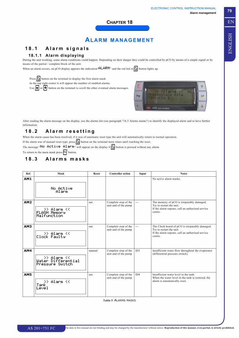
ELECTRONIC CONTROL INSTRUCTION MANUALAlarm management
AS 201÷751 FC
79
EN
GL
ISH
EN
The data in this manual are not binding and may be changed by the manufacturer without notice. Reproduction of this manual, even partial, is strictly prohibited.
CHAPTER 18
ALARM MANAGEMENT1 8 . 1 A l a r m s i g n a l s
18.1.1 Alarm displayingDuring the unit working, some alarm conditions could happen. Depending on their danger they could be controlled by pCO by means of a simple signal or by
means of the partial / complete block of the unit.
When an alarm occurs, on pCO display appears the indication“ ” and the red led of j button lights up.
After reading the alarm message on the display, use the alarms list (see paragraph "18.3 Alarms masks") to identify the displayed alarm and to have further
information.
1 8 . 2 A l a r m r e s e t t i n gWhen the alarm cause has been resolved, if it was of automatic reset type the unit will automatically return to normal operation.
If the alarm was of manual reset type, press j button on the terminal more times until reaching the reset.
The message “ ” will appear on the display if j button is pressed without any alarm.
To return to the main mask press k button.
1 8 . 3 A l a r m s m a s k s
Press j button on the terminal to display the first alarm mask.
In the top right corner it will appear the number of enabled alarms.
Use g or f button on the terminal to scroll the other eventual alarm messages.
Ref. Mask Reset Controller action Input Notes
AM1 No active alarm masks.
AM2 aut. Complete stop of the unit and of the pump
--- The memory of pCO is irreparably damaged.Try to restart the unit.If the alarm repeats, call an authorised service centre.
AM3 aut. Complete stop of the unit and of the pump
--- The Clock board of pCO is irreparably damaged.Try to restart the unit.If the alarm repeats, call an authorised service centre.
AM4 manual Complete stop of the unit and of the pump
ID3 Insufficient water flow throughout the evaporator (differential pressure switch).
AM5 aut. Complete stop of the unit and of the pump
ID4 Insufficient water level in the tank.When the water level in the tank is restored, the alarm is automatically reset.
Table 5 ALARMS MASKS
77 88
77 88
77 88
77 88

ELECTRONIC CONTROL INSTRUCTION MANUALAlarm management
AS 201÷751 FC
80
EN
GL
ISH
EN
The data in this manual are not binding and may be changed by the manufacturer without notice. Reproduction of this manual, even partial, is strictly prohibited.
AM6 manual Complete stop of the unit and of the pump
ID9 Pump 1 overload.
AM7 manual Complete stop of the unit and of the pump
ID10 Pump 2 overload.
AM8 manual Stop of fans and of compressors of circuit 1
This alarm occurs only in the event of fan speed regulation, when the regulator has anomalies during its operation or in the event of overload of fans of circuit 1.
AM9 manual Stop of circuit 1 B1 The temperature value measured by the high pressure transducer of circuit 1 is equal to or higher than the alarm threshold.See Chapter 2 “Pressure and temperature transducers“ .
AM10 manual Stop of circuit 1 The temperature value measured by the low pressure transducer of circuit 1 is equal to or lower than the alarm threshold.See Chapter 2 “Pressure and temperature transducers“.
AM11 manual Stop of circuit 1 ID5 The pressure value of circuit 1 is equal to or higher than the pressure switch setpoint (if the pressure switch is present).
AM12 manual Stop of compressor 1 of circuit 1
ID11 Compressor 1 of circuit 1 overloaded.
AM13 manual Stop of compressor 2 of circuit 1
ID12 Compressor 2 of circuit 1 overloaded.
AM14 manual Stop of circuit 1 --- Error in the pump-down procedure in circuit 1: min. pressure level not reached during the pump-down delay time.
AM15 manual Complete stop of the unit and of the pump
ID13ID18
Anomalies due to the incorrect power supply phase sequence.When the power supply is restored, the alarm must be manually reset.
AM16 manual Stop of the unit, the pump remains on
B4 The temperature value measured by the probe is equal to or higher than the alarm threshold.See Chapter 2 “Pressure and temperature transducers“.
Ref. Mask Reset Controller action Input Notes
Table 5 ALARMS MASKS
77 88
77 88
77 88 # %
77 88 # %
77 88 # %
77 88 # %
77 88 # %
77 88 # %
77 88 # %
77 88
77 88

ELECTRONIC CONTROL INSTRUCTION MANUALAlarm management
AS 201÷751 FC
81
EN
GL
ISH
EN
The data in this manual are not binding and may be changed by the manufacturer without notice. Reproduction of this manual, even partial, is strictly prohibited.
AM17 manual Stop of the unit, the pump remains on
B4 The temperature value measured by the probe is equal to or lower than the alarm threshold.See Chapter 2 “Pressure and temperature transducers“.
AM18 manual Stop of the unit, the pump remains on
B5 The temperature value measured by the probe is equal to or higher than the alarm threshold.See Chapter 2 “Pressure and temperature transducers“.
AM19 manual Stop of the unit, the pump remains on
B5 The temperature value measured by the probe is equal to or lower than the alarm threshold.See Chapter 2 “Pressure and temperature transducers“.
AM20 manual Stop of the unit, the pump remains on
The temperature value measured by the probe is equal to or higher than the alarm threshold.See Chapter 2 “Pressure and temperature transducers“.
AM21 manual Stop of the unit, the pump remains on
B10 The temperature value measured by the probe is equal to or lower than the alarm threshold.See Chapter 2 “Pressure and temperature transducers“.
AM22 manual Stop of the unit, the pump remains on
B1 The probe measures an out-of-range value: it may be damaged, not connected or short-circuited.See Chapter 2 “Pressure and temperature transducers“.
AM23 manual Stop of the unit, the pump remains on
B6 The probe measures an out-of-range value: it may be damaged, not connected or short-circuited.See Chapter 2 “Pressure and temperature transducers“.
AM24 manual Stop of the unit, the pump remains on
B4 The probe measures an out-of-range value: it may be damaged, not connected or short-circuited.See Chapter 2 “Pressure and temperature transducers“.
AM25 manual Stop of the unit, the pump remains on
B5 The probe measures an out-of-range value: it may be damaged, not connected or short-circuited.See Chapter 2 “Pressure and temperature transducers“.
AM26 manual Stop of the unit, the pump remains on the antifreeze resistance starts
B10 The probe measures an out-of-range value: it may be damaged, not connected or short-circuited.See Chapter 2 “Pressure and temperature transducers“.
AM27 aut. Warning --- Complete unit maintenance is required.For further information please consult paragraph "10.2 Working hours and startings of compressors and of the unit".
Ref. Mask Reset Controller action Input Notes
Table 5 ALARMS MASKS
77 88
77 88
77 88
77 88 !
77 88 !
77 88 "# $
77 88 "# $
77 88 " % $
77 88 " % $
77 88 " % $
77 88

ELECTRONIC CONTROL INSTRUCTION MANUALAlarm management
AS 201÷751 FC
82
EN
GL
ISH
EN
The data in this manual are not binding and may be changed by the manufacturer without notice. Reproduction of this manual, even partial, is strictly prohibited.
AM28 aut. Warning --- Pump 1 maintenance is required.For further information please consult paragraph "12.1 Operating hours and number of startings of the pump".
AM29 aut. Warning --- Pump 2 maintenance is required.For further information please consult paragraph "12.1 Operating hours and number of startings of the pump"
AM30 aut. Warning --- Compressor 1 of circuit 1 maintenance is required.For further information please consult paragraph "10.2 Working hours and startings of compressors and of the unit".
AM31 manual Stop of compressor 1 --- One of the two probes connected to the Driver of the electronic thermostatic valve of circuit 1 is damaged or disconnected.
AM32 manual Stop of compressor 1 --- The Eeprom of the Driver of the electronic thermostatic valve of circuit 1 is damaged or has any anomaly.
AM33 manual Stop of compressor 1 --- The step-step motor which manages the electronic thermostatic valve of circuit 1 is damaged or has any anomaly.
AM34 aut. Warning --- The battery which powers the Driver of circuit 1 is down or disconnected.
AM35 aut. Warning --- The pressure probe connected to the Driver of the electronic thermostatic valve of circuit 1 measures a too high value.
AM36 aut. Warning --- The pressure probe connected to the Driver of the electronic thermostatic valve of circuit 1 measures a too low value.
AM37 aut. Warning --- The superheating value elaborated by the Driver of the electronic thermostatic valve of circuit 1 is too low.
AM38 manual Stop of compressor 1 --- At unit stopping, the Driver which elaborates the data of the electronic thermostatic valve of circuit 1 detects that the valve in not completely closed.
Ref. Mask Reset Controller action Input Notes
Table 5 ALARMS MASKS
77 88
77 88
77 88 # %
77 88 $6 %
77 88 $6 %
77 88 $6 %
77 88 $6 %
77 88 $6 %
77 88 $6 %
77 88 $6 % -&9
77 88 $6 %

ELECTRONIC CONTROL INSTRUCTION MANUALAlarm management
AS 201÷751 FC
83
EN
GL
ISH
EN
The data in this manual are not binding and may be changed by the manufacturer without notice. Reproduction of this manual, even partial, is strictly prohibited.
AM39 manual Stop of compressor 1 --- The probe connected to the Driver of the electronic thermostatic valve of circuit 1 measures a too high temperature of the refrigerant fluid suction during MOP operation.
AM40 manual Warning, antifreeze resistance function on
B3 The probe measures an out-of-range value: it may be damaged, not connected or short-circuited.See Capitolo 2 “Trasduttori e Sonde“.
AM41 manual Warning, antifreeze resistance function on
B8 The probe measures an out-of-range value: it may be damaged, not connected or short-circuited.See Capitolo 2 “Trasduttori e Sonde“.
AM42 manual Warning, antifreeze resistance function on
B9 The probe measures an out-of-range value: it may be damaged, not connected or short-circuited.See Capitolo 2 “Trasduttori e Sonde“.
AM43 manual The fans and the compressors of circuit 1 stop
ID8 This alarm occurs only in the event of fan speed regulation, when the regulator has anomalies during its operation or in the event of overload of fans. (free-cooling fans).
Ref. Mask Reset Controller action Input Notes
Table 5 ALARMS MASKS
77 88 $6 %
! " !
#
! " !
$
! " !
% "

ELECTRONIC CONTROL INSTRUCTION MANUALHistory
AS 201÷751 FC
84
EN
GL
ISH
EN
The data in this manual are not binding and may be changed by the manufacturer without notice. Reproduction of this manual, even partial, is strictly prohibited.
CHAPTER 19
HISTORYThe electronic control is furnished with a “history” loop, see Chapter 17 “Masks requiring a password“ and Ref. U1. Inside this loop are stored:
1. the last 50 accesses to User, Service and Manufacturer menus with the appropriate date and hour;
2. the last 50 alarms with the appropriate:
• code of the alarm,• date and hour of tripping;• -BEWIT, -BEWOT and -BTOWT (if present) temperatures at tripping,• high and low pressure at tripping;• status of outlets and inlets at tripping.
NOTEThese data can be reset only after the access to history loop with Manufacturer password.

ELECTRONIC CONTROL INSTRUCTION MANUALSetting Tables
AS 201÷751 FC
85
EN
GL
ISH
EN
The data in this manual are not binding and may be changed by the manufacturer without notice. Reproduction of this manual, even partial, is strictly prohibited.
CHAPTER 20
SETTING TABLESThe following tables show the list of all masks which contain adjustable parameters, important for unit operation.
The absence of any mask on the display is not a malfunction.
ATTENTIONThe displaying of some masks depends on the settings of other masks and also on the unit configuration, decided during design phase.
All masks are identified by means of a code indicated in Ref. column; this code will be used in the manual to identify easily any mask.
On Factory setting column are indicated the setting values set during the unit testing; they are referred only to the unit which has the same serial number you can
find on the label of the first page of this manual.
DANGERThe wrong programming of pCO could cause big damages to the unit.The parameters can be modified by specialized personnel only.
The complete list, of adjustable and not- adjustable parameters and of further information about their use and meaning, can be consulted in the tables inside the
manual.
2 0 . 1 S e t t i n g s w i t h o u t p a s s w o r dATTENTION
The modifying of parameters must be carried out by specializedpersonnel only.
To modify the following parameters see the procedure of Chapter 16 “Masks
no password required“.
Ref. Mask Factory Setting
SET-POINT
C2
C3
C4
C5
C6
!"#$! !"#
C7
C8
USER
D1
D2
See Chapter 21 - Table 6
D3
D4
Ref. Mask Factory Setting
! "# $ ! "# $

ELECTRONIC CONTROL INSTRUCTION MANUALSetting Tables
AS 201÷751 FC
86
EN
GL
ISH
EN
The data in this manual are not binding and may be changed by the manufacturer without notice. Reproduction of this manual, even partial, is strictly prohibited.
2 0 . 2 S e t t i n g s w i t h p a s s w o r dATTENTION
The modifying of parameters with password must be carried out byspecialized personnel only, therefore it is necessary to call anauthorized service centre.
To modify the following parameters see the procedure of Chapter 17 “Masks
requiring a password“.
Ref. Mask Factory Setting
UNIT CONFIGURATION
G3
See Chapter 21 - Table 7
G5
G6
G7
G8
G9
G10
See Chapter 21 - Table 7
G11
G12
BEWIT
1& "#
# %),%+
!
# %)*%+
)151+
" #"
"#"
G13
See Chapter 21 - Table 11
G14
MODULARITY
DRIVER
I5
I6
See Chapter 21 - Table 8
I7
I8
I12
I13
HOURS WORKED
J6
J7
Ref. Mask Factory Setting
# %
-& !"#
!
!"#
& #&

ELECTRONIC CONTROL INSTRUCTION MANUALSetting Tables
AS 201÷751 FC
87
EN
GL
ISH
EN
The data in this manual are not binding and may be changed by the manufacturer without notice. Reproduction of this manual, even partial, is strictly prohibited.
J8
J9
J10
J11
MANUAL OPERATION
K1
K2
K3
K4
K5
K6
K7
K8
Ref. Mask Factory Setting
& % & '
-& %
# %' 0# ' 0
!" #$ #
K9
K10
COMPRESSORS
L1
L2
L3
L4
PUMPS
M2
M3
M4
M5
M6
Ref. Mask Factory Setting
& % & '

ELECTRONIC CONTROL INSTRUCTION MANUALSetting Tables
AS 201÷751 FC
88
EN
GL
ISH
EN
The data in this manual are not binding and may be changed by the manufacturer without notice. Reproduction of this manual, even partial, is strictly prohibited.
M7
FANS
N3
N4
N5
N6
N9
UNLOADING
O1
O2
O3
RECOVERY
DEFROSTING
ALARMS
Q10
Ref. Mask Factory Setting
!" -& !"#$! !"#
-& % !-& ' !
% -& % !-& ' !
%
-& # -& !$! !
! !
CLOCK
R1
R2
R3
R4
R5
HYSTORY
S4
SUPERVISOR
U1
U2
U3
U4
U5
Ref. Mask Factory Setting
$
! ""
! ""
!" # $
%" &' &
()( '

ELECTRONIC CONTROL INSTRUCTION MANUALSetting Tables
AS 201÷751 FC
89
EN
GL
ISH
EN
The data in this manual are not binding and may be changed by the manufacturer without notice. Reproduction of this manual, even partial, is strictly prohibited.
OTHER SETTINGS
V1
V2
V3
V4
FREECOOLING
W2
W3
W5
See Chapter 21 - Table 10
W6
W7
See Chapter 21 - Table 9
W8
See Chapter 21 - Table 9
Ref. Mask Factory Setting
!" !
#$ % -& !"#$! !"#
& % -& !"#$! !"#
W9
W10
Ref. Mask Factory Setting
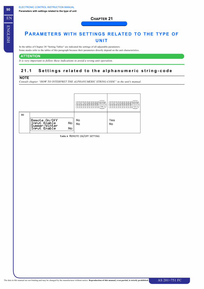
ELECTRONIC CONTROL INSTRUCTION MANUALParameters with settings related to the type of unit
AS 201÷751 FC
90
EN
GL
ISH
EN
The data in this manual are not binding and may be changed by the manufacturer without notice. Reproduction of this manual, even partial, is strictly prohibited.
CHAPTER 21
PARAMETERS WITH SETTINGS RELATED TO THE TYPE OF UNIT
In the tables of Chapter 20 “Setting Tables“ are indicated the settings of all adjustable parameters.
Some masks refer to the tables of this paragraph because their parameters directly depend on the unit characteristics.
ATTENTIONIt is very important to follow these indications to avoid a wrong unit operation.
2 1 . 1 S e t t i n g s r e l a t e d t o t h e a l p h a n u m e r i c s t r i n g - c o d eNOTEConsult chapter “HOW TO INTERPRET THE ALPHANUMERIC STRING-CODE” in the unit's manual.
D2
Table 6 REMOTE ON/OFF SETTING
! "# $ ! "# $

ELECTRONIC CONTROL INSTRUCTION MANUALParameters with settings related to the type of unit
AS 201÷751 FC
91
EN
GL
ISH
EN
The data in this manual are not binding and may be changed by the manufacturer without notice. Reproduction of this manual, even partial, is strictly prohibited.
G3
G10
Table 7 PROBES SETTING / TANK
AS351 FC-AS401 FC AS501 FC ÷ AS751 FC
I6
Table 8 CONSTANT REG. PID-CH
BEWIT
)151+

ELECTRONIC CONTROL INSTRUCTION MANUALParameters with settings related to the type of unit
AS 201÷751 FC
92
EN
GL
ISH
EN
The data in this manual are not binding and may be changed by the manufacturer without notice. Reproduction of this manual, even partial, is strictly prohibited.
2 1 . 2 S e t t i n g s r e l a t e d t o t h e u n i t m o d e l
N Version SN Version SSN Version
W7
W8
Table 9 SPEED CONTROL
W5
Table 10 FAN REGULATION TYPE
AS 201 FC ÷AS 301 FC AS 351 FC ÷ AS 751 FC
G13
Table 11 PUMP-DOWN PROCEDURE ENABLE
# %