a security platform using software defined … security platform for software defined infrastructure...
TRANSCRIPT

A Security Platform Using Software Defined Infrastructure
by
Mohammad-Sina Tavoosi-Monfared
A thesis submitted in conformity with the requirements for the degree of Master’s of Applied Sciences
Electrical and Computer Engineering
University of Toronto
© Copyright by Mohammad-Sina Tavoosi-Monfared 2016

ii
Abstract
A Security Platform for Software Defined Infrastructure
Master’s of Applied Science
Electrical and Computer Engineering
University of Toronto
2016
In this work, we designed an architecture for cloud network security, leveraging Software
Defined Infrastructure, which enables centralized management of compute and networking
resources. We show that utilizing SDI’s service chaining and its Software Defined Networking
approach, network security functions such as intrusion detection and prevention, as well as
distributed firewalls can be realized as services in the cloud, as modeled in Network Function
Virtualization. In our platform, protective resources are located as close as possible to the entity
being protected. Furthermore, the design of the user-friendly interfaces for these services to be
used is discussed, where the user traffic flows are associated with Enhanced Security Profiles,
together forming Enhanced Security Groups. We also discuss our implemented proof-of-concept
on SAVI testbed.

iii
Acknowledgments
I would like to thank my family, especially my parents, for all the help and guidance they have
provided me up to this stage in my life.
I would like to thank my advisor, Professor Alberto Leon-Garcia, for his kind supervision and
guidance.
I am very thankful to the SAVI team, in particular, Thomas Lin and Hadi Bannazadeh for all
what they taught me, as well as the resources they provided, which enabled me to implement my
architecture on the SAVI testbed.
Last, but not the least, I am thankful to University of Toronto, and the city of Toronto as a whole,
for being an amazing community. I am, and forever will be a proud Torontonian, for the
harmony of its diverse cultures.

iv
Table of Contents
Acknowledgments.......................................................................................................................... iii
List of Tables ................................................................................................................................ vii
List of Figures .............................................................................................................................. viii
List of Acronyms .............................................................................................................................x
Chapter 1 Introduction and Problem Statement ...............................................................................1
1.1 Motivation ............................................................................................................................1
1.1.1 Cloud Security Needs ..............................................................................................1
1.1.2 Categorization of Cloud Security Mechanisms .......................................................2
1.1.3 Network Security Paradigm Shift ............................................................................3
1.2 Problem Statement ...............................................................................................................7
1.2.1 Interoperable NIDPS Platform .................................................................................7
1.2.2 Platform Scalability and Component Coordination .................................................8
1.2.3 Scope of Research ....................................................................................................9
Chapter 2 Background and Related Work .....................................................................................12
2.1 Background ........................................................................................................................12
2.1.1 Software Defined Networking (SDN) ...................................................................12
2.1.2 Network Function Virtualization (NFV) ...............................................................13
2.2 Software Defined Infrastructure ........................................................................................15
2.2.1 Conceptual Architecture ........................................................................................15
2.2.2 Opportunities and Capabilities in Providing Security ...........................................17
2.3 Related Work .....................................................................................................................18
2.3.1 IDS Frameworks for the Cloud ..............................................................................19
v
2.3.2 IDS Interface Design..............................................................................................22
Chapter 3 Overview of Hybrid Security Platform .........................................................................24
3.1 High-Level Design .............................................................................................................24
3.1.1 Design Requirements .............................................................................................24
3.1.2 High-Level Design Components............................................................................28
3.2 Design Considerations .......................................................................................................36
3.2.1 Design for Scalability ............................................................................................36
3.2.2 Design for Testability ............................................................................................40
3.2.3 Design for Extensibility .........................................................................................41
3.2.4 Design for Cost Management ................................................................................41
3.2.5 Design for Self-Protection .....................................................................................42
3.3 Interoperable IDS API .......................................................................................................43
3.3.1 Integration with Analytics-based Detection...........................................................44
3.4 Distributed Mitigation System ...........................................................................................45
Chapter 4 Software Architecture and Implementation ..................................................................47
4.1 Deployment Architectures .................................................................................................47
4.2 SDI Enabler ........................................................................................................................50
4.3 Enhanced Security Groups .................................................................................................51
4.4 Prototype Implementation ..................................................................................................52
4.4.1 IDS Appliances ......................................................................................................53
4.4.2 Component Placement ...........................................................................................55
4.4.3 Configuration API ..................................................................................................56
4.4.4 Master Coordination Agent....................................................................................56
4.4.5 Software Configuration Agents .............................................................................58
4.4.6 Load Balancer ........................................................................................................59

vi
4.4.7 Auto-scaling ...........................................................................................................62
4.4.8 Web User Interface ................................................................................................63
Chapter 5 Testing and Evaluation ..................................................................................................68
5.1 Functional Verification ......................................................................................................68
5.2 Testing Methodology .........................................................................................................70
5.2.1 Parameters of Interest ............................................................................................71
5.3 Test for Detection Time .....................................................................................................74
5.4 Test for Relative Delay Measurement ...............................................................................80
5.5 Test for Scalability .............................................................................................................83
5.6 Tests for Detection Accuracy and Information Integrity ...................................................91
Chapter 6 Conclusion .....................................................................................................................95
6.1 Overall Evaluation .............................................................................................................95
6.2 Future Work .......................................................................................................................96
6.3 Contribution .......................................................................................................................97
References or Bibliography ...........................................................................................................99

vii
List of Tables
Table 5-1 – Chosen Testing Parameters
Table 5-2 – Summary of the Experiment Measuring the Detection Time of Different Security
Sensitivities
Table 5-3 – Round Trip Times (RTTs) for the three VA Scenarios
Table 5-4 – Round Trip Times (RTTs) for the two PA Scenarios
viii
List of Figures
Figure 1-1 – Typical DMZ Style Firewall Deployment
Figure 2-1 – Conventional Switches vs. SDN-based Switches
Figure 2-2 – SDI Components
Figure 2-3 – Realization of Security Module in SDI
Figure 3-1 – Attack from Outside Scenario
Figure 3-2 – Attack from Inside Scenario
Figure 3-3 – General Resource Coordination Architecture
Figure 3-4 – High-Level Components
Figure 4-1 – Flat Deployment / Communication Architecture
Figure 4-2 – Hierarchical Deployment / Communication Architecture
Figure 4-3 - VA Implementation Using Virtual Machine including Snort and OVS – Note the
direction of traffic
Figure 4-4 – Detailed Components of Master Agent
Figure 4-5 – Distributed Load Balancing Scheme
Figure 4-6 – Distributed Load Balancing Scheme
Figure 4-7 - Sign in Page of the GUI
Figure 4-8 – VM List Page of the GUI
Figure 4-9 – ESP Page of the GUI
Figure 4-10 – Chaining Page of the GUI
ix
Figure 5-1 – Verification of Chaining Using Ping and TCPDUMP
Figure 5-2 - Test using Netcat utility (The packet containing "attack" string from samplevm4 to
samplevm3 is dropped)
Figure 5-3 – VA Test Using a Low Sensitivity DoS Threshold
Figure 5-4 – VA Test Using a Medium Sensitivity DoS Threshold
Figure 5-5 – VA Test Using a High Sensitivity DoS Threshold
Figure 5-6 – PA Test - Low Sensitivity
Figure 5-7 – PA Test - Medium sensitivity
Figure 5-8 – PA Test - High Sensitivity
Figure 5-9 – Total BW against time for scenario A
Figure 5-10 – Total resource number scaling as the BW sum increases in a step-like manner
Figure 5-11 – Number of Low/Small IDS Resources vs. the total inspection bandwidth over time
Figure 5-12 – IDS-1 and 2 Resource Utilizations and Bandwidths throughout the experiment
Figure 5-13 – IDS-3 and 4 Resource Utilizations and Bandwidths throughout the experiment
Figure 5-14 – Expected growth rate of packet loss for a given IDS
Figure 5-15 – The attack used the second scenario to measure the packet loss
Figure 5-16 – Iperf test, first without an attack, and then under an attack scenario

x
List of Acronyms
API – Application Program Interface
AD – Anomaly Detection
ASIC – Application Specific Integrated Circuit
BW – Bandwidth
CAPEX – Capital Expenses
CDN – Content Distribution Network
CPU – Central Processing Unit
DAQ – Data Acquisition
DB – Database
DDoS – Distributed Denial of Service
DST – Destination
DMZ – Demilitarized Zone
DNS – Domain Name System
DoS – Denial of Service
DPI – Deep Packet Inspection
ESG – Enhanced Security Group
ESP – Enhanced Security Profile
FPGA – Field Programmable Gate Array
FW – Firewall

xi
GDP – Gross Domestic Product
GUI – Graphical User Interface
HIDS – Host-based Intrusion Detection System
HTTP – Hypertext Transfer Protocol
HTTPS – HTTP Secure
IAM – Identity and Access Management
IDS – Intrusion Detection System
IDEMF - Intrusion Detection Message Exchange Format
IETF – Internet Engineering Task Force
IP – Internet Protocol
IPS – Intrusion Prevention System
IT – Information Technology
LB – Load Balancer
LTE – Long Term Evolution
M&M – Monitoring and Measurement
MAC – Media Access Control
NetFPGA – Network Field Programmable Gate Array
NIDS – Network Intrusion Detection System
NIPS – Network Intrusion Prevention System
NIDPS – Network Intrusion Detection and Prevention System
xii
NIST – National Instantiate for Standardization Technology
NFV – Network Function Virtualization
OPEX – Operational Expenses
OVS – Open vSwitch
PA – Physical Appliance
QoS – Quality of Service
RC – Resource Controller
REST (RESTful) - Representational State Transfer (based)
RMS – Resource Management System
ROC – Rate of Change
RTT – Round Trip Time
SAVI – Smart Application for Virtual Infrastructure
SDI – Software Defined Infrastructure
SDN – Software Defined Networking
SQL - Structured Query Language
SRC – Source
SSH – Secure Shell
SW – Software
TCAM –Ternary Content Addressable Memory
TCO – Total Cost of Ownership
xiii
TCP – Transport Control Protocol
TLS – Transport Security Layer
UI – User Interface
VA – Virtual Appliance
VM – Virtual Machine
VNF – Virtualized Network Function
VPC – Virtual Private Cloud
VPN – Virtual Private Network
VXLAN - Virtual Extensible LAN
WAN – Wide Area Network

1
Chapter 1 Introduction and Problem Statement
In this chapter, we discuss the general motivation, the direction of the cloud network security
paradigm, and state the particular problem we tackled.
1.1 Motivation
1.1.1 Cloud Security Needs
In order to motivate the significance of our discussion on cloud network security, we begin by
reviewing some recent statistics that are relevant to our work. In 2015, it was estimated that the
total annual cost of malicious cyber-attacks ranges from $100 Billion to $1 Trillion (US dollars)
[1] [2] [3] (Compare this number with Canada’s 2015 GDP, estimated to be $1.548 Trillion [4]).
From 2014 to 2015, there was an increase of 38 percent in detected security attacks [5]. The
average length of time a hacker stays inside a network undetected is estimated to be over 140
days [6]. In a survey of 814 qualified IT security decision makers (for organizations with at least
500 employees), at least 52 percent of them anticipated there would be a successful attack on
their network infrastructure within the year 2015 [7]. These statistics increasingly relate to cloud
computing. In the case of global organizations, they increasingly use clouds. In 2015, only about
38 percent of global organizations see themselves ready to mitigate sophisticated attacks [8].
One may feel the attractiveness of cloud for hackers by looking at NIST’s definition of cloud
computing: “Cloud computing is a model for enabling ubiquitous, convenient, on-demand
network access to a shared pool of configurable computing resources” [10]. In particular, the
cloud is to be available everywhere, be able to launch attacks on-demand, with convenient
remote access. It is hard to find a hacker that would not love such technology. In 2015, it was
estimated that about 6.5 million unique hosts were leveraged by cyber criminals to launch attacks
[11]. There are many clusters of “unique” hosts available on the cloud, making it lucrative for
hackers to gain hands on.
Similarly, clouds are increasingly becoming an exotic target for attackers. Due to its economy of
scale, both small and large enterprises have been moving part or their entire computing

2
operations to the cloud. This implies that we shall see an increasing shift in targets. The statistics
around that are not surprising at all. Exploits affecting corporate and internal networks have
grown to 40% in 2015, up from 18% in 2014 [12].
On the other hand, the detection of cyber-attacks has remained a difficult task. In 2015, an
organization that investigated billions of security events in 17 countries, reported that 59%
percent of the victims did not discover the breaches themselves. While cloud is attractive for
attacks both originated from and targeted to it, it is evident that conventional frameworks have
many shortcomings in dealing with cloud network security. We will discuss these shortcomings
in the sections ahead.
1.1.2 Categorization of Cloud Security Mechanisms
The term “security” may have many different connotations. In order to properly scope our work,
we propose a brief categorization of cloud security mechanisms into four main types:
1- Encryption-based: Utilizing Encryption, Hashing, Virtual Private Networks (VPNs), etc.
to ensure confidentiality and integrity. There are approaches both at lower and higher
layers (end-to-end).
2- Intrusion Detection based: The topic of our work, covered in the background chapter.
3- Hypervisor / OS-based: Isolation of processes, and possibly including a firewall below
the Virtual Machine (VM).
4- Virtualization Based: E.g. Network slicing using Software Defined Networking (SDN),
or adding proxies to SDN controllers. Not a direct topic of this work.
3
1.1.3 Network Security Paradigm Shift
In order to understand the current trends in the network security industry, we first review the
traditional network security frameworks. Then, we state our understanding and anticipation of
the current trends in network security.
1.1.3.1 Conventional Firewalls and the DMZ Model
Traditionally, the most frequently used module in network security has been the firewall. The
firewall is an entity that monitors ingress and egress traffic, taking actions (i.e. allow traffic to
pass or else block it) based on a set of pre-defined rules [13]. In particular, firewalls prevent
exposure / access to certain software ports. The firewall may be implemented in hardware or
software, be hosted (within a computer) or external (as a separate module or box). With a hosted
firewall (e.g. the default Firewall that comes with the operating system), usually the unused /
unnecessary software ports are closed. In the case of an external firewall, packets that can be
identified (by looking at the packet headers) as communicating with certain unwanted ports are
dropped.
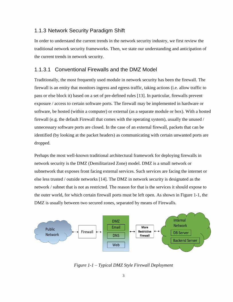
Perhaps the most well-known traditional architectural framework for deploying firewalls in
network security is the DMZ (Demilitarized Zone) model. DMZ is a small network or
subnetwork that exposes front facing external services. Such services are facing the internet or
else less trusted / outside networks [14]. The DMZ in network security is designated as the
network / subnet that is not as restricted. The reason for that is the services it should expose to
the outer world, for which certain firewall ports must be left open. As shown in Figure 1-1, the
DMZ is usually between two secured zones, separated by means of Firewalls.
Figure 1-1 – Typical DMZ Style Firewall Deployment

4
In cloud computing, firewalls are not implemented quite the same way, and hence are often
named differently, namely “Security Groups”. A Security Group acts as a virtual firewall [15],
usually implemented at the hypervisor. Hypervisor is the entity dividing the underlying physical
infrastructure in order to provide virtualization / virtually isolated chunks of resource (i.e. Virtual
Machines (VMs)). A Security Group may be used for one or more VM instances in the cloud.
Besides the policy and port range, security groups may also include direction (inbound or
outbound) or specific source addresses (e.g. open the email port only for communications
from/to a specific IP address).
The DMZ model has shortcomings when applied to the cloud. In particular, the DMZ model
relies on the assumption that one network / subnet can be more trusted than another. However,
how can one define the interior and exterior and draw such borders in a cloud, particularly a
public one? In particular, in a given public cloud, there may be VMs of various entities running
on the same physical machine at any given point in time.
1.1.3.2 Intrusion Detection and Prevention Systems
Besides the firewalls and DMZs, we shall review the concept and evolution of Intrusion
Detection Systems (IDSes) as well as Intrusion Prevention Systems (IPSes). An IDS is a reactive
module that is used to detect attack traffic, while an IPS is an active module that would prevent /
mitigate detected attacks (e.g. by re-routing or blocking incoming attack traffic). IDSes come in
different types. These include the following:
1- Signature/Pattern-based: They tend to be network based, looking for specific
signatures patterns within the packet header and payload. Their advantage is that their
detection accuracies for the attacks with well-known signatures are known to be high
(e.g. over 99%). In particular, they almost lack false positives (unless the signature
assigned to them is dual-use).
2- Analytics-based: This type of IDS typically detects deviations from a norm / baseline,
which is established using a mathematical model. As such, an alternative name for
this category is Anomaly Detection (AD). AD may detect the authenticated users

5
merely demonstrating a strange usage pattern as an attack, labeling a perceived
regular activity as anomalous (i.e. false positive) [16].
Another IDS classification can be done based on the platform monitored. In particular, we have
the following categories:
1- HIDS (Host-based IDS): In this category, the detection system regularly monitors the
system logs, processes, file system, and the network interface (from inside the host
machine).
2- NIDS (Network-based IDS): The IDS of this type operates at the network layer, by
looking at the packet header and the content of the network / IP layer. This thorough
inspection operation is called DPI (Deep Packet Inspection), which involves looking at
the payload [17]. If the NIDS is capable of blocking the attack traffic, (E.g. through inline
placement) it is then noted as an NIDPS (Network Intrusion Detection and Prevention
System).
In the next Chapters, we propose an interoperable model where IDSes of different categories
may integrate together to form a complex IDS system. In particular, an AD Detection module
may work together with a signature-based IDS for further verification. For the most part, we
focus on signature-based NIDPSes, as our proof-of-concept is majorly built with that.
1.1.3.3 The New Paradigm
Going back to the question of cloud network security, even if we were able to draw the lines
between the trusted and untrusted networks in the cloud (e.g. through use of Virtualized
Networks), the port-based firewall technology is inherently flawed, as it can never deal with
vulnerabilities that exist in traffic belonging to the well-known ports (e.g. SQL injection).
Clearly, Packet header information does not provide sufficient criteria for malware detection. As
attacks become more sophisticated, the defenses have had to become more detailed and fine-
grained.
To answer the challenge, a new paradigm in network security has emerged. In this new
paradigm, the defenses are rather located closer to the resource being protected, sometimes
6
located at the application layer itself. This is the approach that Google has chosen [18]. In
particular, they have been brining security operations (access control, authentication, and
authorization) to the application layer and do not use the traditional firewalls. This framework is
also along the famous “Application knows the best” argument (also known as “the end-to-end
argument”) [19]. Other cloud landscape trends include the growth of in-house custom software to
increase security. In addition, the interior security is now just the same as perimeter, as if it’s all
perimeter. This is reflected in Google’s Zero Trust Model, treating the internal and external
networks (e.g. Internet) the same. This is said to be in the direction of a paradigm shift in the
security of future networks [20].
Nevertheless, when it comes to network security, the solution we provide in this work is a mix of
local and global, inside and on the network edge security. There are situations with attacks that
can be best mitigated in the switches or edge routers. For those attacks, it is the networking and
infrastructure layer that can more efficiently be deployed to block the attack. This is especially
the case for DoS (Denial of Service) and DDoS (Distributed Denial of Service) attacks. These
attacks take advantage of a device or service being network connected, typically by flooding it
with traffic requests [21]. At times, these attacks require an asymmetry of resources, sometimes
can be achieved by the overhead of application layer processing (making the flooding info more
time and resource consuming to process).
Of course, the borders of the layers are increasingly collapsing, and our work is aligned with this
trend, too. The new paradigm, as we will see in the case of SAVI (Smart Applications for Virtual
Infrastructures), is to have the network infrastructure have accessible API for the so-called
“smart” applications (perhaps they get their “smartness” from the exceptional access they have to
control the network infrastructure). If not already, this may be a game changer in the networking
world in the years to come.
Therefore, DMZ is increasingly replaced with security groups that act as a defense circle close to
the exact entity being supported. As mentioned, while HIDSes are easier to install and configure,
the network flavor of security could be more effective, especially in terms of mitigation.
We need ever more scalable security orchestration to protect our clouds. Furthermore, we need to
minimize the amount of human labour we require by automating tasks as much as possible.

7
Likewise, it is preferable to be able to control the security platform in a logically centralized
way. At the same time, the security infrastructure itself may be distributed in implementation in
order to scale. In particular, any platform shall be able to auto-scale up and down based the
demand.
Platforms are growingly become adaptive in terms of their decision making. Establishing future
trends in input demand, learning future from the past is increasingly added to business
production solutions [22]. Similarly, Analytics-based attack detection techniques are increasingly
integrated together with the conventional security schemes [23].
As well, as we discuss in our NFV (Network Function Virtualization) section, network security
is increasingly moving from “appliances” to a set of services (e.g. honeypot, IDS, Firewall, etc.)
that are connected through service chaining. Such ecosystem of virtualization, cloud, and NFV,
motivates inter-operability, and hence industry players are increasingly co-operating through
Open Source communities [24].
Motivated by these, our solution places security defenses closer to the resources being protected,
scale on demand at the scale of the cloud, and it is interoperable to provide the space for mixing
and matching, and being creative.
1.2 Problem Statement
In this section, we define the exact problem we attempted to solve. In particular, we shall note
the scope of our solution, in terms of what it covers and what it does not. While defining the
scope is important in general, it is extra important in the security field.
In short, our problem is to design a cloud network security platform, which realizes a scalable
architecture for NIDPS deployment. This design is to provide automation, scaling, and
coordination among the network security components. In the next sections, we will discuss our
problem and objectives in further detail.
1.2.1 Interoperable NIDPS Platform
NIDPSes come in many shapes and forms. There are many different implementations of them,
including the following: Proprietary hardware: ASICs (Application Specific Integrated Circuit),
8
Standard computer hardware (e.g. x86 architecture), NetFPGA hardware (and hardware
description language), Software (e.g. Snort), Virtual appliance (which is usually a virtual
machine, container, etc.).
More importantly, NIDPSes come from different vendors. In general, the vendors do not like
their enterprise customers to be able to mix and match their products with their those of their
competitors. The consequence is a lack of interoperability. This is one important objective of the
problem we attempted to solve, to come up with a design that provides interoperability for
NIDPSes, such that they can communicate and coordinate with each other.
Such architecture enables hybrid and heterogeneous solutions. Hybridity here primarily means
the ability to include physical and virtual resource (within the same solution / ecosystem). For
that, as we discuss in Chapter 3 and 4, we had to come up with a systematic approach to
abstracting the IDS resources, regardless of what vendor or what implementation it comes from.
While the overall trend may be moving towards virtualized resource, there has already been vast
CAPEX (Capital Expenses) spent on the legacy physical devices, which we note as PAs
(Physical Appliances). As well, virtualized resource (noted as VAs (Virtual Appliances)) tend
not to match the dedicated hardware’s performance (in both Bandwidth (BW) and delay).
Nonetheless, the VAs may perform the role of overflow. The only other alternative to that is to
further increase the capital investments to acquire a greater number of hardware-intensive PAs.
Of course, that approach comes with increased OPEX (Operational Expenses), too [25].
Hence, interoperability matters as it enables flexible IDS platforms to be realized. While
interoperability is important by itself, perhaps a main driving force for it in today’s context of
cloud computing is the increasing need for scalability, which as we discuss in the next
subsection. Scalable solutions be realized through hybrid utilization of virtualized resources in
addition to physical ones.
1.2.2 Platform Scalability and Component Coordination
Scalability, in general, may be defined as a measure of the system capability to increase its
performance [26], in our case, for a growing input traffic / demand. To put this into perspective,
one may consider the case of an enterprise such as Hewlett Packard (HP). It has been estimated
9
that in 2013, HP had to deal with 1 trillion security events per day, which amounts to roughly 12
million events per second [27]. Without scalability in mind, no solution can ever be designed to
match that level of input inspection traffic.
With cloud’s ever increasing growth in size, the security apparatus has to scale as well. That is
why scalability is a key component of our problem, and we chose it as an objective, detailed in
Chapter 3 and 4. As mentioned, the main goal we consider for virtualized resources is to act as
overflow, essentially increasing the scalability of the system.
As we will discuss in the next chapters, a particular type of attack we focus on a lot in this work
is DoS / DDoS attacks. The reason for that is this type of attacks makes up one of the two major
categories of attacks that signature-based NIDSes detect. In these attacks, the response time from
detection to mitigation (e.g. blocking, rerouting, or honey potting the traffic) matters a lot. We
discuss that in details in another work of ours [28]. In particular, in the case of DoS attacks, the
higher the delay, the more problematic traffic is allowed in the network, potentially slowing
down other connection, not just those of the targeted service node(s).
As we will discuss, the scalable approach about blocking these attacks is to have a distributed
architecture in both detection and mitigation (e.g. blocking at the edge of the network). However,
the distributed architecture should not result in increased detection to mitigation delays. In order
to aim for reduced attack response times, we seek an in-depth integration of detection and
defenses measures. For that, coordination matters a lot. As we discuss in Chapter 4, having
logically centralized decision makers plays an important role in providing this coordination.
1.2.3 Scope of Research
In this section, we discuss what we intend to cover. More importantly, we state what we will not
be covering. In this work, we focus on designing a DPI / signature-based NIDPS platform
architecture for clouds. We do not cover design of Analytics-based detection. As well, we will
not be getting into the details of the DPI algorithms (e.g. Boyer-Moore pattern match [29]). This
implies that we treat the NIDS modules as black boxes for the most part. As well, we are not
concerned with adding new signatures to IDSes. While we do identify the need for a signature
update scheme, we do not detail a design for that feature.

10
Likewise, we do not aim to cover a great number of exploits as use cases or for testing. Of
course, we will categorize the attacks in general, and will have a representative of each kind in
our testing and measurement as well as our use cases. The single type of attack we most focus on
is DoS. For the most part, we consider DDoS attacks as an extension of DoS. In practice, AD-
detection schemes may provide much better detection for DDoS attacks as well as outright abuse
of the system for authenticated users than signature-based detection. However, an in-depth
comparison of IDSes of different types is outside our scope. Security may have inherently
become a big data problem (E.g. the example we mentioned on HP in the last subsection, with 1
trillion security events per year). However, we do not cover big data techniques, rather aim for
the scalability of our platform.
Likewise, our testing will be limited to very basic attack types. We do not perform our testing
with real captured traffic, as that may require very specific signatures. It is commonly said that a
100% secure system does not exist unless the system is in complete isolation (which would make
it useless). We do not claim our work is a direct security solution. Rather, our work is an
architectural framework that can motivate a real solution.
Our work does not provide a sophisticated security alert management system. In particular, for
our defense system, we simply block any suspicious traffic, which may imply an underlying
assumption that the signature-based NIDSes have a near perfect accuracy (of course, this is a
safer / militarized approach, false blockings may be reported and dealt with separately). While
we believe signature-based detection provides better detection accuracy for attacks with well-
known signature, different categories of inaccuracies (false positive, false negative) may exist. In
fact, the accuracy of the IDS is a function of the accuracy of the signature, and how well is has
been correlated with various attack and non-attack traffics. However, we do not perform a
detailed study on that.
It is crucial to emphasize that our signature-based platform does not detect zero-day attacks. As
well, it may not detect unusual usage patterns. As mentioned before, Analytics-based IDSes may
detect these two categories, however, at the cost of reduced overall accuracy. In particular, there
are certain anomalies that may be just an unusual yet valid usage pattern (e.g. one of the staff
who has traveled to a part of the world in a different time-zone has logged into the system, which

11
was a different UTC time). These type of anomalies typically don’t cause any issues with
signature-based detection, since in signature-based detection there is no use of clustering
algorithms. However, they may get flagged by anomaly detection system. This is a typical false
positive situation in Analytics-based solutions, while that would not typically happen on our
platform. Hence, there are trade-offs that need to be considered when choosing between AD and
signature-based detection.
Needless to say, DPI-based detection is not directly useable for encrypted traffic. There are
various schemes to deal with encrypted traffic, such as a militarized approach where unapproved
encrypted traffic (i.e. encrypted with an unapproved key) may be simply dropped. However, we
do not concern the management of encrypted traffic, as this is a wider security aspect of the
cloud network, which is outside the scope of our architecture.
12
Chapter 2 Background and Related Work
In this chapter, we will introduce background concepts and some of the terms that are frequently
used throughout the thesis.
2.1 Background
2.1.1 Software Defined Networking (SDN)
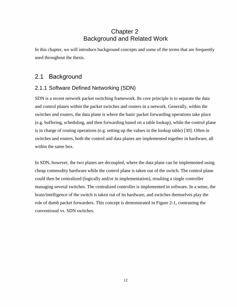
SDN is a recent network packet switching framework. Its core principle is to separate the data
and control planes within the packet switches and routers in a network. Generally, within the
switches and routers, the data plane is where the basic packet forwarding operations take place
(e.g. buffering, scheduling, and then forwarding based on a table lookup), while the control plane
is in charge of routing operations (e.g. setting up the values in the lookup table) [30]. Often in
switches and routers, both the control and data planes are implemented together in hardware, all
within the same box.
In SDN, however, the two planes are decoupled, where the data plane can be implemented using
cheap commodity hardware while the control plane is taken out of the switch. The control plane
could then be centralized (logically and/or in implementation), resulting a single controller
managing several switches. The centralized controller is implemented in software. In a sense, the
brain/intelligence of the switch is taken out of its hardware, and switches themselves play the
role of dumb packet forwarders. This concept is demonstrated in Figure 2-1, contrasting the
conventional vs. SDN switches.

13
Figure 2-1 - Conventional Switches vs. SDN-based Switches [31]
The most significant implementation of SDN to this date is OpenFlow, which is a standardized
protocol for the controller and dumb switches to communicate [31]. OpenFlow controllers
instruct the switches to act on incoming packets according to certain rules, which are called”
flows” in the SDN context. Flows can be used to classify packets according to almost all L2, L3,
or L4 header fields (e.g. ingress Ethernet port number, MAC and/or IP destination addresses,
choice of IP and/or transfer layer protocol, Layer 4 port numbers) [32]. Hence OpenFlow
switches tend to have flow tables instead of simple forwarding tables, which are populated
typically using Ternary Content Addressable Memory (TCAM).
SDN is particularly relevant to our work in two aspects, the first is service chaining, and the
latter is our distributed defense system. As we discuss in the next section, the service chaining
we utilize is implemented using SDN / OpenFlow under the hood. As well, our distributed
defense relies on the SDN-based firewall we implemented. We described the distributed firewall
in detail in [28], and we will revisit it again later in this thesis.
2.1.2 Network Function Virtualization (NFV)
Network Function Visualization is a recent framework where various network functions are
classified into distinct building blocks/modules, where they can be implemented in a virtualized
manner [33]. Such building blocks are called Virtualized Network Functions (VNFs). Examples
of the VNF abstraction would be Virtual Machines (VMs) within a multi-tiered cloud that

14
perform specific network functions such as Load Balancing, Firewall, Encryption, Virtual
Private Network (VPN), Wide Area Network (WAN) Accelerators, and DPI. The modules/VMs
may then be chained together to provide the intended network services. In its radical form, NFV
attempts to virtualize the entire network functions and nodes.
In terms of objectives, NFV clearly attempts to bring the well-known advantages of
virtualization into the world of networking. Such general advantages include scalability, reduced
overall power consumption (by dynamically turning on and off the underlying hardware), and
reducing Total Cost of Ownership (TCO) by reducing both CAPEX and OPEX. However, in our
view, the most significant potential advantage of NFV, in comparison to the unabstracted
networking service models from the past, is its enabling of more than ever rapid innovation as
well as flexibility in assigning hardware. One can see the latter through the capability of
migration of network services/VNFs from cloud to cloud or cloud edge to cloud core, so long as
the delay requirements can be met [25].
Next, we discuss Security as a Service within NFV. Several security operations introduced above
can be implemented as VNFs, such as encryption, firewall, DPI, NIDS, NIPS, and VPN [34].
Implementing these as VNF has many advantages, perhaps most importantly, the scalability.
For firewall, it can be located at the edge of the cloud, to keep attacker outside the cloud as far as
possible. This is meaningful when considering DOS attacks that make the cloud nonfunctional
by leaving little to no bandwidth for its essential network operations.
Thanks to VM live migration technology [35], system administrators can have little to no
downtime for network topology update procedures. Implementing DPI itself in software than
buying proprietary hardware boxes, huge cost savings are introduced [28]. Also, for NIDS and
NIPS, the security platform could scale up and down its software based DPI resources on the fly,
and have a dynamic security investigation policy according to the sensed scale of an attack.
SDN is crucial for the VNF implementation of such security services, as SDN enables the system
to dynamically adjust flows that connect or disconnect certain network nodes. Also, say if we
have limited DPI computing resources/limited number of expensive DPI hardware boxes, then
we could use SDN to sample a portion of the network traffic at a time by looping through flows.

15
In this thesis, we argue that network security of a cloud can be modeled as a network function
and then realized as a service. Hence, as we shall see, our work has an NFV flavour to it, as our
implementation of NIDPS as a service can be modeled as a VNF.
2.2 Software Defined Infrastructure
In this section, we introduce Software Defined Infrastructure (SDI), and a particular
implementation of it, code-named Janus. As part of that, we review Smart Application for
Virtual Infrastructure (SAVI) testbed, which is a multi-edged cloud platform we leveraged to
implement our architecture.
2.2.1 Conceptual Architecture
Software-defined Infrastructure is a new architectural framework for supporting applications by
virtualization and integrated management of converged heterogeneous resources in a multi-tiered
cloud [36] [37]. SDI's goal is to enable programmability of both the cloud applications and
network functions by providing High-Level abstraction interfaces for programmers and their
applications. Heterogeneous resource types include computing, programmable hardware (e.g.
NetFPGAs), and networking resources.
In essence, SDI combines Software Defined Network (SDN) and Cloud Computing to realize an
infrastructure where applications can be deployed rapidly and with increased flexibility, taking
advantage of virtualized heterogeneous resources and sliced network.
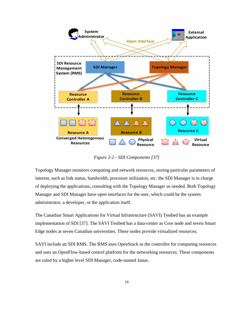
Figure 2-2 depicts the components of the SDI Resource Management System (RMS). The RMS
has various Resource Controllers (RCs), each of which providing the resource-specific support
(i.e. similar to hardware specific drivers). The RCs are accessed and managed through two
higher level modules, SDI Manager, and the Topology Manager.
16
Figure 2-2 - SDI Components [37]
Topology Manager monitors computing and network resources, storing particular parameters of
interest, such as link status, bandwidth, processor utilization, etc. the SDI Manager is in charge
of deploying the applications, consulting with the Topology Manager as needed. Both Topology
Manager and SDI Manager have open interfaces for the user, which could be the system
administrator, a developer, or the application itself.
The Canadian Smart Applications for Virtual Infrastructure (SAVI) Testbed has an example
implementation of SDI [37]. The SAVI Testbed has a data-center as Core node and seven Smart
Edge nodes at seven Canadian universities. These nodes provide virtualized resources.
SAVI include an SDI RMS. The RMS uses OpenStack as the controller for computing resources
and uses an OpenFlow-based control platform for the networking resources. These components
are ruled by a higher level SDI Manager, code-named Janus.
SDI Manager Topology Manager
Resource Controller A
Resource Controller B
Resource Controller C
SDI Resource Management System (RMS)
Open Interface
External Application
System Administrator
Resource CResource BResource A
Converged Heterogonous Resources
PhysicalResource
VirtualResource
17
2.2.2 Opportunities and Capabilities in Providing Security
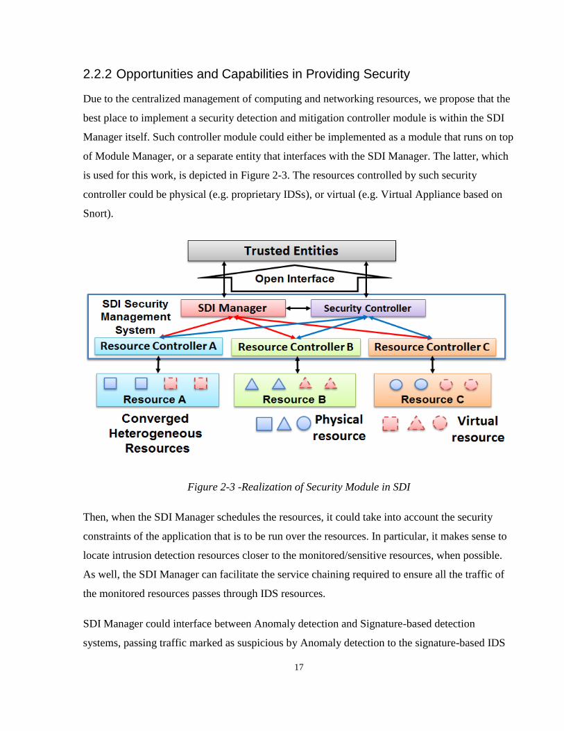
Due to the centralized management of computing and networking resources, we propose that the
best place to implement a security detection and mitigation controller module is within the SDI
Manager itself. Such controller module could either be implemented as a module that runs on top
of Module Manager, or a separate entity that interfaces with the SDI Manager. The latter, which
is used for this work, is depicted in Figure 2-3. The resources controlled by such security
controller could be physical (e.g. proprietary IDSs), or virtual (e.g. Virtual Appliance based on
Snort).
Figure 2-3 -Realization of Security Module in SDI
Then, when the SDI Manager schedules the resources, it could take into account the security
constraints of the application that is to be run over the resources. In particular, it makes sense to
locate intrusion detection resources closer to the monitored/sensitive resources, when possible.
As well, the SDI Manager can facilitate the service chaining required to ensure all the traffic of
the monitored resources passes through IDS resources.
SDI Manager could interface between Anomaly detection and Signature-based detection
systems, passing traffic marked as suspicious by Anomaly detection to the signature-based IDS

18
for further investigation. This is particularly useful in a scenario where we have limited Deep
Packet Inspection resources for IDS.
Also, having access to all OpenFlow switches, SDI Manager could help to realize a distributed
firewall to block attacker traffic anywhere within the platform, most importantly in the gateway
switches and routers. Once an attacker has been identified, the header fields associated with the
attack packets (e.g. source IP address) can be passed to SDI Manager to install blocking rules in
all the switches within the path to the victim. This SDI mechanism leverages SDN.
Finally, the SDI Manager could be used in orchestrating security resources, giving higher
priority to hardware-based and NetFPGA based IDSs (due to their superior bandwidth, lower
latency, and higher power efficiency), using Virtual Appliances as overflow. The interfacing
with Janus SDI is further discussed in the design chapters.
As mentioned, besides the distributed firewall, SDI provides us with an interface for service
chaining. Increasingly, providing a traffic chaining capability is becoming important. Most cloud
providers, however, do not provide that at the moment. Hence, this justifies our choice of SAVI
Testbed, due to its Janus chaining API available. We discuss the chaining API that our work
leverages in detail in Chapter 4.
2.3 Related Work
Our work is certainly not the first attempt in solving the general cloud IDS deployment and
management problem. In this section, we review and analyze the relevant literature. As well, we
state how our solution is different from the past research, starting in this section, and furthered in
the contribution section of Chapter 6.
Before we being our review, we shall note that in order to have an in-depth analysis, we limit our
review to two particular classes of work. We found these two to be most related to our work. The
first category is IDS framework design, and the latter is IDS interface design. In terms of other
areas that did not dive deep into, we would like to mention load balancing and service chaining.
For example, in [38], a general framework for middle box service chaining and load balancing is
presented. However, such designs tend to be more general and not pertain to particular security

19
needs. Nevertheless, the paradigm involved is same as ours. For instance, we similarly realize
our load balancing using centralized service chaining (discussed in Chapter 5). We now move to
discussing the two main categories of interest, which is the topic of the next two subsections.
2.3.1 IDS Frameworks for the Cloud
In this subsection, we go over the related work in Cloud IDS Architecture for security resources.
We start with a detailed review of the work by Roschke et al. [39], as it is the most closely
related work to ours. In their paper, they perform an analysis on the requirements of IDS
deployment in the cloud and propose an architecture for the management of IDSes. Their goal,
which we share, is to make the IDS utilization more user-friendly for non-administrator users in
a cloud environment. To some extent, the architecture they present resembles the hierarchical
deployment scheme we discuss in Chapter 4. In particular, they recommend IDSes to report to a
central management module, which is also in charge of remotely controlling the IDSes. As well,
we intersect with them on the idea of a feature that enables the user being able to communicate
with the cloud to pick their desired IDS. They similarly propose correlating IDS alerts to gain
higher accuracies / bigger picture.
Nevertheless, their work merely focuses on detection and not on prevention. As such, they
consider no network security defense (e.g. blocking the traffic at a switch). Hence, there is no
feedback to the networking resources.
Admitted by the authors, their work does not address scalability (and orchestration). As well,
their work almost lacks any proof-of-concept, which they state as a future work. For their data
acquisition, they merely rely on the hypervisor to provide monitoring info (similar to the case of
SAVI Monitoring and Measurement system, which we discuss in a later subsection). However,
in practice, such tapping point by the hypervisor may or may not be exposed to the developer by
the cloud infrastructure. In that sense, as we will see in the next chapters, our data acquisition
(DAQ) system is more general, as our polling-based DAQ has no such requirement. As well,
they provide no comparison to other platforms.
Then, they state that it is the Cloud provider’s responsibility to provide various IDS VMs as well
as the enabling attachment of virtual IDSes to specific VMs. By doing so, they do not consider a
20
well-defined scheme for the user to communicate their security requirement and have the
management system map them to corresponding IDSes (in Chapter 4, we introduce the notion of
Enhanced Security Profiles (ESPs), particularly dedicated to solidifying a communication
scheme / protocol for this very purpose).
Their scheme is centralized in implementation (not just logically). Yet they do not provide a
scheme to increase the resiliency of their system (in the event of the centralized manager going
down). Likewise, they consider no self-protection scheme for their system (e.g. for the event of
the IDS controller itself being under attack). In addition, their platform only focuses on virtual
resources, in particular, a combination of virtualized NIDS and application layer HIDS, and not
NIDSes of different types (physical vs. virtual).
They delegate the responsibility of assigning a particular IDS to the user itself, and do not
consider sharing IDSes for a user’s traffic of the same security requirement. Their solution lacks
an automated IDS assigner and load balancer. Therefore, while their work has certain similarities
to ours, it generally states a set of (at times vague) ideas than solidifying them in the
specification or realizing them in practice.
Next, we briefly discuss the work of Dhage et al. [40]. They also attempt to solve the problem of
detection in a distributed cloud ecosystem by providing an IDS model for the cloud. Unlike
Roschke et al., they consider mitigation as part of their cloud IDS platform. Their platform
deploys individual “mini” IDSes per user. These mini IDSes are managed by node controllers,
which may contain other mini IDSes of other users. Each controller performs analysis on the
IDSes it manages. Their assignment scheme is different than ours, and as we will analyze, we
find our IDS to user flow assignment / categorization more efficient in terms of resource
utilization.
Next, in [41], the authors outline an architecture for DDoS detection using collaboration among
the IDSes. In particular, their solution deals with a vast number of logs, and they present a
quantitative solution (based on Dempster-Shafer Theory) for analyzing alerts. However, their
work only considers virtual appliances.
21
In [42], the challenge considered is the case of customers of a public cloud requiring to
implement their own Virtual Appliance based IDS in the cloud. For that, they suggest a very
simple architecture that has 3 components, the IDS VM, a management VM, and possibly a load
balancer VM. Their work does not utilize overlays, SDN, and recent chaining techniques, instead
using Amazon's Virtual Private Cloud (VPC) to force the traffic to pass through the IDS VM.
In [43], a framework for sharing IDS data across various levels of infrastructure as well as across
different clouds is presented. The authors hope that their framework would lead to collaborative
IDS clusters across many clouds.
In [44], a scheme for sharing trust in a distributed IDS platform is distributed. In particular, they
argue that increasing collaboration between the IDSes results by providing them with a scheme
to decide whether or not accept an alert result in reduced detection time. The work only covers
DoS attacks, and they only consider the case of virtual appliances.
In [45], again the DoS attacks are tackled, this time for a distributed implementation in both
detection and prevention. They suggest placing IDS at cluster controller, which is the highest
entity managing the orchestration / computing aspect of the VMs, through a hierarchical scheme.
They also discuss the idea of having one IDS per physical machine. However, this approach may
not be scalable, as the individual VM traffic may vary, possibly resulting in low levels of
resource utilization. As well, it does not consider the case of VMs within a physical machine
attacking one another.
In [46], the authors describe a simple scheme to deal with DDoS, by observing for traffic spikes.
In the event of a spike, they pass the traffic through IDS, log all the traffic, and if no SYN ACK
detected they send it to the honeypot. Their system seems not to consider many of the general
cases, as it focuses merely on TCP SYN ACK flood (we used this attack in our testing, too).
Scalability concerns of the matter are not visited at all. Hence, ignoring the security orchestration
aspects of the problem. Their IDS implementation, however, has a similarity to ours. In
particular, they assume that the DPI software is installed in the virtual switch, which happens to
be similar to our implementation of VA. However, our VAs are not primarily designed as
switches. In our case, the virtual switch is rather used to facilitate the traffic chaining through the
IDS program.

22
In [47], the authors present the idea of implementing CIDS (Cloud IDS), which is an IDS
platform, as a network service. They have a dedicated layer for the database operations, which
perhaps makes the memory operations of their system more efficient. However, their work does
not concern interoperability and extensibility for the IDS platform. As well, they do not consider
orchestration, as their system is merely controlled by the users, without any load balancing.
2.3.2 IDS Interface Design
Next, we review the IDEMF (The Intrusion Detection Message Exchange Format) protocol [48].
Introduced by IETF (Internet Engineering Task Force) in 2007, it is an attempt to design a
unifying protocol for IDS and IPS communications. The primary purpose of this protocol is to
define a universal format for IDS-related information, which in turn may enable coordination
among separate security devices and the management modules. The devices and modules may
come from different vendors, and IDEMF emphasizes on interoperability and extensibility.
While IDEMF has been around for a while, it is individual vendor’s choice to implement an
interface based on it or not. As discussed, vendors typically do not desire to implement
interoperable protocols. This is the reason that our work does not rely on the NIPDS
device/module to implement this protocol or not.
As well, IDMEF’s extensibility comes at the price of increased overhead, both in terms of added
communication overhead as well as computation (parsing). If a platform is to implement
IDMEF, it cannot just support part of it, it either covers it all or not. We did not require all the
functionalities included in IDMEF. For that reason, we decided not to implement it. Our main
purpose is to abstract resources, regardless of what interfaces they come with, and so long as the
abstracted resources share a consistent interface, that suffices for us. As mentioned, the cloud
industry trend is moving towards in-house custom solutions to increase security. Having a
universal communication protocol is inherently in contradiction with that.
In [49], the authors designed a console to view Snort alerts and Graphical User interface, namely,
SnortStarf, to use the Snort IDS. One especial scenario considered by them is an attacker
intentionally filling up Snort log with decoy logs to overwhelm a human operator, for which they
suggest an algorithm to visually divide up the alerts in the display such that the human operator

23
could find an anomalous event in O(log N) interface operations. The work is perhaps useful for
small scale personal systems where a human operator would occasionally check the logs.
However, all bigger systems need some degree of automation to find and process certain event
logs.
Finally, in [50], the authors present an interface design for applications to report their exceptions
to the IDS (e.g. if they expect a false positive is going to be generated). However, one may argue
that having such interface itself adds to the threat vector.

24
Chapter 3 Overview of Hybrid Security Platform
In this chapter, we discuss our architectural framework, which is the essence of our design. We
will go over the high-level design, starting by stating the design requirements, then covering the
overall components and use cases. Then, we have dedicated a section to design considerations,
where we state the particular features and design decisions made in order to meet
3.1 High-Level Design
In this section, we discuss the high-level design, which includes the architecture. We shall first
explore the purpose of our architecture, which is best stated in terms of its design requirements.
3.1.1 Design Requirements
Design requirements are important as they determine the extent of the design’s success. Such
requirements can be categorized into functions, objectives, and constraints [51]. Functions are
the expected behaviour of the system. Functional requirements that are either met or not (binary),
and they describe the general / abstract application of the design. Then, objectives are set of
goals, which can be met to a certain degree, and hence we need to have specific criteria to
measure the extent to which they are met (as well as defining their “success” line). Constraints
could be thought of as objectives that must be met; otherwise, the design is inherently flawed /
will fail anyway.
The first function of the security platform is to detect attacks that have a well-known signature.
Such signature may be in the packet header or else in the payload. It is important to emphasize
here that our method of detection is limited to information pattern detection per packets from the
traffic of a certain flow / link. Similarly, our scope of detection is limited to those attacks that
happen to have a signature / packet information pattern, that is possible to detect, and is already
associated with a well-known attack. It is important to note that this IDS method does not detect
zero-day attacks. As well, it does not detect misuse of the system, while as mentioned before,
anomaly-based IDSes could detect those, too. However, again, the advantage of pattern based
IDSes is in their relatively less rate of false positives and detection errors, which stems from the

25
fact that unlike anomaly-based detection, they do not leverage probabilistic models or machine
learning.
The second function of the system is to mitigate the attacks. Essentially, our platform not only
includes IDS but also IPS, making it a cloud NIDPS platform. The mitigation may come in
different forms. The options include blocking the packets generated from a certain source,
immediately upon detection, as well as potentially blocking the future packets from the same
source. Another possible action is to provide a honeypot as service, re-routing the traffic to the
honeypot. Honeypot is essentially a duplicate of the attacker’s target server, but with less to no
service value (i.e. it is not providing actual service to the clients). This target server is left open
to the attacker so that the attack can be investigated after it is over [52]. Its concept is similar to
sandboxing in the broader cyber-security, except the target server may or may not be actually
sandboxed, depending on how advanced the honeypot system is. A proper sandbox involves
restricting the actual access of the attacker to the system [53], and hence creating such decoy
server is a more sophisticated procedure.
Next, we discuss the objectives of our design. The first objective is the architecture has to be
scalable, in different ways (horizontally and vertically), for various components (detection,
mitigation, management, etc.). In particular, the detection capability has to scale based on:
number of flows (with “flow” defined as pair (src, dst)), flow bandwidth. Then, the mitigation
has to be scalable in the sense that the defense is to be modular, and distributed. With a
distributed defense, we could have a feedback to the switches, as we showed in [28].
The feedback to the switches ensures that the blocking action is not only done that the NIDPS
modules, but also at the edge switches and routers. This, in turn, avoids bottlenecks at the inline
IDSes. For instance, software based IDSes, such as Snort, tend to suffer from limited processing
bandwidths. Their typical bandwidth is multiple times lower than regular commodity switches
(based on our measurements, detailed further in the evaluation section). This makes sense, as
they have to do computation and processing the packet contents. Even the most efficient IDSes
(e.g. ASIC or FPGA based ones) do not provide throughputs in the scale of switches. Hence,
scalability in inspection bandwidth matters a lot, and that could be the ultimate purpose of our

26
platform. In the real world, software base IDSes are most likely only used for overflow capacity.
This overflow feature ties back to the concept of scalability, which matters a lot in our work.
Our second objective is for the platform design and architecture to be interoperable. In our view,
interoperability can be best defined by the capability to include both physical and virtual
appliances (PAs and VAs), from various vendors. Our idea of such ecosystem where PAs and
VAs live around each other is certainly inspired by the Network Function Virtualization
paradigm, where ultimately it should not matter in any way to the user whether the resource used
in physical or virtual (to the point that it is even suggested that should be fully hidden from the
user) [54].
To be realistic, however, we do have to define the scope to which we hope to be interoperable. In
particular, the NIDPS implementations that we are to include shall meet certain minimums, in
that they should provide certain minimal functionalities (e.g. Deep Packet Inspection) as well as
a well-defined interface to use their products. The interface should include features such as the
ability to program remotely, push attack events, or pull attack logs. Our design is to take
detection and mitigation implementations (which meet the criteria described) as black boxes. Our
security resources are to be chosen such that they are not already interoperable, and then we add
a computation layer that abstracts the resource. This is again in line with NFV’s vision.
Our interoperability objective makes more sense when one looks at the possible trends for NFV’s
universal adoption. In NFV’s vision (which itself is inspired by the general vision and direction
of cloud computing), virtualized resources will eventually become ubiquitous, which is due to
their long-term cost efficiency. However, enterprises have already spent huge sums of money on
the Capital Expense for the legacy / proprietary / physical detection and mitigation equipment
they have. For now, they are not going to throw away their old firewall machines right away.
Therefore, there will be a possibly long transitionary period, during which both new virtual and
old physical appliances have to work together. As well, as mentioned, physical appliances may
be more power efficient for their specialized sort of computation (as opposed to x86 hardware).
Hence, we felt the urge to design a hybrid platform that would abstract and include both virtual
and physical resources.

27
It also worth noting that our notion of interoperability inherently includes extensibility embedded
into it. Extensibility may be defined as the capability to extend the design / framework to include
new elements. In our case, extensibility is defined by the ease of adding a new network security
resource to the framework. This closely ties together with interoperability, in the sense that if our
design is interoperable, it should be relatively easy to include new resource types in it. At the
same time, modularity in design helps with extensibility. Similar to object-oriented
programming, where adding a new module is usually adding a new class, our architecture is to be
designed to be modular, so that adding new resources does not require a significant change in the
architecture, design, or previously written code.
Now that we have defined our main objectives (scalability and interoperability), we should also
define how we intend to measure the extent of our success in meeting them. For intrusion
detection scalability, perhaps the best way to measure is to look at the growth rate of the size and
the number of required resources as the input demand grows. The input demand can be modeled
in various ways, such as the number of traffic flows (again, flow defined by the pair (src, dst)),
individual flow bandwidth, or total inspection traffic size per unit time (inspection throughput).
Therefore, for example, if we define a function, where an input is the size of total inspection
traffic, and the output is the number of unit intrusion detection modules used, we are interested to
look at the limiting behaviour of it. Ideally, if the growth is linear, this would imply that our
system is scalable. We define such functions more precisely, and discuss our measured growth
rates for them in our evaluation section.
Next, when it comes to our other objective, namely, interoperability, it is similarly difficult to
define a quantitative measure for its success. An ideally interoperable cloud network security
platform should be able to include any possible or existing NIDPS resource in it. However, as
mentioned, we have reserved some basic requirements for the NIDPSes so that we are able to
abstract them, to begin with. Stating that assumption, we have already limited the set of NIDPS
resources we may include (e.g., some NIDPS resource may not include an API that enables to
program them remotely). Nevertheless, we may still try to define a basic measure, such as the
capability to include at least two virtual appliances and 1 physical appliance, all from different
vendors. However, “being from different vendor” is rather vague when it comes to intrinsic of

28
the resources, as the resources may be very similar inside, just come in different brands.
Considering all this, perhaps the best approach is to have a qualitative measure than a
quantitative one. In particular, we argue that our platform is able to work with a great majority of
the products out there in the market. We perform a more detailed analysis in our evaluation
section.
One may wonder, why keeping the cloud secure is not noted as an objective of ours. This is a
crucial scoping consideration. In particular, it is very difficult to define a measure for security.
Even if we define one, our work relies on certain parameters that are outside our control. For
example, the assumption of whether an attack has a well-known signature or not relates to the
field of IDS design and signature extraction, which is outside the scope of this work. Hence, we
do not aim for the security in a direct manner, rather, by coming up with a scalable platform
design for existing IDS technology and existing attack signatures.
3.1.2 High-Level Design Components
In this section, we discuss our architecture by going over its high-level design components. In
order to understand the components and the architecture, we first discuss our typical use cases.
From there, we move on to our architecture and workflow.
3.1.2.1 Use Cases
As our work is about cloud network security, our use cases all involve some attack traffic
coming into or through a cloud network. For the typical use cases of the cloud network security
platform, we shall consider all possible attack origins. This is again, due to the fact that the
periphery is undefined or else very hard to be defined in a cloud network. Our attack scenarios
include cyber-attacks from the within, as well as those from outside, which have some network
footsteps involved in them. This is almost the case for all the attacks in the cloud, as they all tend
to require the access to the virtual machine, which is on the hypervisor host, to be done remotely
(i.e. they don’t allow people to walk in and connect to the hypervisor directly).
The attack may be generated within the cloud network, or from outside networks. Using a setup
that is explained in the workflow section below, all user flows pass from an assigned IDS. The
user flows have two end hosts, one the user host (which may be within or outside the cloud
29
network) and one server host (which is within the cloud network). We shall note that our notion
of “cloud network” is intentionally vague for generalization, as such notion may be realized in as
the actual cloud local area network, a particular virtual network, or an isolated subnetwork.
Regular user traffic experience shall significant difference. Attacks are to be detected, through
IDSes that the user flows are chained through. Again, by attack here, we mean attacks that
already have a well-known signature, detected over plain-text packets (i.e. not encrypted). Once
an attack is detected, it is to be both immediately blocked inline, and as well, a feedback to the
relevant switches / routers is provided to block future packets originating from the attacker.
From here on, we assume that our given cloud network is SDN-based. We argue that this
assumption, while strictly speaking is not required, does not hurt the generality of our work. In
particular, SDN seems to increasingly dominate the cloud network paradigm, due to its economy
of scale, and its harmony with a virtualized environment, as one of SDN’s main consequences, is
to virtualize the network itself [55]. SDN also very much matches our framework (e.g. it already
has “flows” modeled in it, suitable with our definition of user flow). Conveniently, we may call
having SDN-based network a constraint of our implementation, since the only cloud networks
we had access to at the infrastructure level for our proof-of-concept were SDN-based. However,
this can also be seen as a design implementation decision, where we chose SDN due to its
capability to rapidly innovate and experiment with its current open source implementations (e.g.
OpenFlow).
Figure 3-1 depicts the attack from outside scenario, while Figure 3-2 shows the scenario of attack
from the inside. In the case of the attack from outside, the attack can best be blocked at the
Gateway / Edge Router, preventing it to get into the cloud network at all. In the scenario of
attack originating from inside, however, the best place to block the attack is the switch that is
nearest to the attacker’s host.

30
Figure 3-1 – Attack from Outside Scenario
Figure 3-2 - Attack from Inside Scenario
It is important to note that NIDS and DPI entities have been used interchangeably in the two
figures, implying that our NIDS is DPI / signature-based. This module is a logical entity, and
may be distributed in implementation (e.g. a load balancer dividing the inspection task), which is
more scalable.

31
As we will mention in our implementation section, our platform leverages SDI Enabler for traffic
chaining, and not using SDN controllers directly. However, we depicted the module as controller
above, as it is a more generic representation.
In SDN’s perspective, there is no inherent difference between a switch and a gateway (as their
control plane is separate from them, anyway). This greatly fits our use cases, as in one attack
comes from outside the cloud network, while in the other it originates from the within. One
attack type passes through the Gateway Router, while the other passing through the Ingress
Switch. SDN enables us to provide the same feedback (of the attacker’s address), regardless of
the audience being the router or the switch.
3.1.2.2 Architecture Workflow
In this subsection, we discuss the workflow of the platform that takes place behind the scenes,
and then review the high-level components of our architecture. When a user host first initiates
contact with a server on the cloud, the user flow traffic, denoted by (src, dst), is assigned an IDS
resource. What layer will be used for addressing (e.g. Data Link (MAC), or network (IP
address)) will be specified in Chapter 4. The assignment of the flow to the IDS may take into
account several factors. One is latency or Quality of Service (QoS) constraints the user might
have. The users of the user flows that are to be treated specially need to have notified the
administrator in advanced about it. Packets of the user flows with high sensitivity delays need to
be assigned to physical resources, which are known in general to have less delay overhead
(again, due to specialized hardware designed to efficiently parse through the packets than
bringing it all the way to the application/software layer).
Based on the QoS requirements, we expand the user flow to become the following triplet: (src,
dst, delay sensitivity). The delay sensitivity is a binary/flag parameter of which values are “low”
or “high”. Our assumption is that we are already provided with a pre-defined list of all sensitive
users so that we can mark them as “high” or “PA only”.
A possible extension of delay sensitivity assignment is automatic traffic characterization, where
for example, a module assigns the sensitivity by looking at the protocol used in traffic (e.g.
streaming vs. download). However, we did not implement that as part of proof-of-concept. This

32
feature may be more difficult to implement as the nature of communication in a user flow may
change over time, so which requires the system to be state-full and dynamic.
Another important note on the PA assignment is that the utilization of the PA has to be taken into
account, too, not to overwhelm it with too many high sensitivity flows (i.e. not ruin the QoS of
past user flows since we need PA for more flows). By default, our system would assign the high
sensitivity flows to regular / VA type of IDS resource. In addition, if a user flow is found to be
rogue or too overwhelming, it may be reassigned a regular weight IDS (VA) upon the detection
of such behaviour / bandwidth usage pattern.
Next, we discuss the high-level architecture and a more detailed workflow based on it. Figure 3-
3 depicts the general scheme we use for the communication and coordination of our NIDPS
resources. In this scheme, we use software agents to abstract the security resource, such that the
resources are somewhat unified from the viewpoint of the main point of control, which we call
the “Master Agent” (our Master Agent is realized as “Master Security Controller”, later on).
Once the resource is abstracted, the Master Agent can treat the resources as a black box, yet
program it using the API provided by the associated SW agent. Hence, for example, the IDS may
be a legacy / specialized hardware based IDS, VA, or NetFPGA-based. More generally, the IDS
might be even a Host-based one. This should make almost no difference to the Master Control
(excluding the delay requirements, as explained earlier). Similarly, the IPS module may come in
different implementations, a legacy hardware firewall, a software one, or a distributed SDN-
based one. Besides the SW agent, what enables this scheme is the common interface shared by
the SW agents, which is described in more details towards the end of this chapter.

33
Figure 3-3 – General Resource Coordination Architecture (Hierarchical)
This general approach, as we will outline in the last subsection of this section, is inspired by
SDI’s architecture, bringing heterogeneous resources together. Some of the resources may be
virtualized, while some are not. This is, again, also in line with NFV’s envisaged ecosystem.
The Master Agent decides on the coordination of resources, how is work divided, which user
flow is assigned to what IDS (as we will explain later, user flows are not to be broken between
IDSes). This Master Agent is a logical entity, which may be distributed in implementation, in
order to distribute the trust among components. This goal is equivalent to not reducing single
points of failure. In particular, we do not want to lose the control over the security resources in
the event of the compromise of the Master Agent.
The Master Agent may also coordinate with an Analytics based detection module, which we call
“M&M Anomaly Detection”. The name is inspired by SAVI’s M&M (Monitoring and
Measurement) module. The naming also stems from the fact that in order to have analytics based
anomaly detection, one needs to have some M&M / Data Acquisition system within their cloud
system, recording parameters / features that reflect on the resource usage profile (such atypical
usages can be detected).

34
Figure 3-4 depicts the high-level components of the system, which is also useful in visualizing
the workflow. The detailed pre-attack / setup workflow is as follows:
1- Through Admin UI (User Interface), RESTful Config API, and then configuration API,
IDS sensor requirements are passed to the SW agents, where they use their Appliance
Specific Configuration API to program the IDS resources.
2- At the beginning of communication, IDS flows (for the forward and reverse paths) are
assigned by the Load Balancers (based on delay sensitivity, and IDS throughput/resource
utilization). The traffic is chained by the SDI Manager through use of the SDI Enabler
API.
Figure 3-4 – High-Level Components
35
The Admin UI may be command-line based and / or a Graphical User Interface (GUI, for
example, a webpage) that only network administrator(s) of the cloud have access to. It leverages
a RESTful Network Security Configuration API, which we have designed, to communicate the
administrator’s network security requirements to the network security platform system. This is
more detailed in the next chapter.
There are a few points that need to be mentioned regarding the representation in Figure 3-4. In
terms of the reverse path load balancer, it is a design decision to allocate the reverse traffic to the
same IDS that was assigned for the forward-path or not. In particular, it depends on whether the
attacks we are to detect require knowledge of the traffic both ways or not. As well, for the
reverse path chaining, in addition to the use of SDI Enabler, we implemented it using a tunneling
scheme, as well. We will discuss this scheme, as well as its pros and cons in Chapter 4.
Also, one may notice that there are components in Figure 3-3 that are not in Figure 3-4. The
components that were not included in the actual proof-of-concept are not present in Figure 3-4.
However, we mentioned them in Figure 3-3 to point out that in general they could be done. We
will revisit this in our future work section.
Then, the post-attack workflow is as follows:
1- The attack gets detected and blocked inline immediately by the assigned IDS.
2- At the sampling/polling point, the associated SW agent notices change in log file of
IDS (through Polling API), parses the attacker address, and passes it to the
coordinator agent, which then uses the SDI Enabler API to install the appropriate rule
in the first accessible switch / gateway on the path from the attacker to server. In
general, the IDS itself may also have the capability to push the events to its assigned
SW agent, but the pull-based model seems to be more encompassing (as it is unlikely
to have a device / module that pushes events but does not have the logs available to
pull the events from).
In the model shown in Figure 3-4, the SW Agent is in charge of both configuring as well as
pulling / reading events from the IDS. However, these two tasks could have been further broken
down to be assigned to separate logical entities. For sake of simplicity / ease of visualization, we
36
combined the two. Logical entities may be implemented together or separately, the placement of
logical entity is an implementation problem, to be visited in Chapter 4.
Lastly, we overview the Anomaly Detection (AD) Correlation Workflow, which is the following:
1- M&M Anomaly detection module requests the traffic of a resource (either a specific
pair (src,dst) or all of a resource traffic) to be inspected, through AD Coordination
API. This API would be very similar, if not the same as, to the RESTful Config API.
2- Rest of the workflow is same as pre-attack setup.
The AD Correlation feature may be used to verify traffic flagged as suspicious by the M&M AD
module. In particular, for attacks with well-known signature, the signature-based IDSes tend to
have a lower rate of error / inaccuracies in detection as opposed the AD modules. Hence, this can
be used to investigate certain portions of network traffic, similar to a police officer contacting a
specialized detective of a certain field to investigate a certain case in further detail and provide
their feedback to increase their sense of certainty around their guesses. This is also similar to
getting second-hand opinions from other sources.
3.2 Design Considerations
In this section, we have designed our network security platform such that it can perform the
necessary functions and meet the requirements we identified for it earlier. In particular, the main
headings of this chapter will read as “Design for X”, a terminology derived from the principles
of engineering design [51]. We recall that our two main objectives were scalability and
interoperability; here we address the design decisions made for them.
3.2.1 Design for Scalability
As mentioned in our design requirements section, the scalability of the platform itself has
multiple dimensions / different aspects in both definition as well as evaluation. The subsections
here are to address some of these various aspects.
37
3.2.1.1 Horizontal vs. Vertical Scaling
The number of users and their extent of server utilization varies throughout time. This means that
the amount of traffic to be inspected also varies accordingly. Our NIDPS platform is to scale
based on the demand.
First, we shall discuss the scaling of the detection resource. The act of scaling may be performed
in different ways. In particular, it may be done horizontally or vertically. Horizontal scaling (aka
scaling in and out) involves increasing the number of detection resource instances, working
together to provide a larger detection bandwidth. This requires load balancing, which is
discussed in the next subsection. Vertical scaling (aka scaling up and down), on the other hand,
involves increasing or decreasing the size of a particular resource, in particular, adding more
CPU, memory, storage, etc. [56]. Vertical scaling tends to have a limit, as the size of one
resource may only be increased to a certain point. The limit may be due physical constraints,
such as rack size limitation, size limitations, hardware limitations, and hypervisor utilization by
other virtualized resources. However, horizontal scaling tends to be more flexible.
As a result, we made the design decision to go majorly with horizontal scaling. Of course,
vertical scaling remains an option to the cloud administrator (i.e. they can use the cloud
infrastructure API directly to increase the individual size of certain virtualized resources / virtual
machines). In fact, vertical scaling is useful where one wants to increase the bandwidth of a
certain flow, beyond the point of capacity that a certain IDS provides. It is important to note that,
in general, user flow break up between a number of IDSes (more than one) is undesirables for us.
More specifically, the issue is with the attack information that may be in a user flow traffic, and
breaking it up may result in counts of certain pieces to be distributed, in the way that the
threshold of each IDS is not met for them to detect the traffic as attack any longer. This problem
may be solved by distributed design of IDS itself, which is out of the scope of our work.
While breaking up to multiple flows is not an option for us, should a flow exceed the current
limitations of a virtual resource, the resource may be scaled up. However, beyond a certain point,
it might make sense to move a very demanding flow back to PAs, as they tend to be more power
efficient, and in general provide less operational costs.
38
3.2.1.2 Load Balancer
Now that we decided that our scalability would be mostly based on horizontal scaling, we shall
review the important piece that enables such scaling feasible, which is called load balancer. Load
balancer, as the name suggests, is a module that divides an input load over a number of
processing resources. It is a technology commonly used for the websites that have significantly
high demands. It is particularly interesting to us as we have decided on a distributed IDS
approach (again, for scalability reasons).
Our load balancer, however, may be a bit different than the typical website / web services load
balancers, in that once the flow is assigned to a certain server (in our case, an IDS module, of
which traffic has been chained through it), the server is not going to change. On the other hand,
in web services, there may be a shared database service with a more distributed server system,
where any component / server instance might pick up the request and respond to it. Hence, our
situation is somewhat more complicated, requiring constraints on the load balancer behaviour. It
can be round robin on the initial assignment, but cannot do round robin per packet or per
individual user requests / segments of user flow traffic.
Initial assignment may be done in several ways. As already mentioned, it could be a simple
round robin. However, we may happen to have some information regarding the expected /
anticipated user flow traffic pattern over time. Utilizing these probabilistic assumptions, we can
come up with an assignment algorithm that on average does better than round robin.
We came up with a greedy IDS assignment algorithm, which tries to not only optimize over cost
/ power usage but also ensures that there is always some overflow there in case there are surges
in the traffic that need to be investigated by the NIDS platform. This is particularly crucial, as
our measured IDS VA up time (using SAVI’s cloud platform, which is based on OpenStack,
which is obviously not the best in terms of performance) in the scale of minutes. We do not want
the users to have to wait minutes for their connection set up, nor do we want to allow
uninspected traffic through. Hence, the algorithm had to take all the time availability of overflow
IDSes as an objective, too.
39
In order to realize our algorithm, we implemented a distributed monitoring / DAQ system, where
SW agents collect certain resource utilization data. This scheme is discussed in detail in Chapter
4. As part of our algorithm design, we decided to use CPU utilization percentage as the main
deciding factor for the algorithm. The rational for this selection is explained in Chapter 5.
To ensure spawning enough overflow resources for any point in time, one may consider
including calculations based on the rate of change. We considered an advanced machine learning
or analytics-based algorithm for this purposes out of the scope of this work, falling in the general
category of orchestration and cloud resource planning, not so much for the network security
discussion (this is the reason that in the industry, they implement big projects in teams!). The
algorithm first checks if the user flow is of high delay sensitivity (e.g. 4G LTE traffic), in which
case, it sees if it can assign to the PA (by looking at how utilized the PA is and how many user
flows of what weight have been assigned to it already). If either of the two conditions is not met,
it starts looking at the size of the requested user flow (small, medium (default), large), as well as
assignment and utilization logs of the existing VA resources. If any of them is free enough, it
assigns it to them. Otherwise, it assigns to the overflow VA resource, as well as calling for
another overflow VA resource to be spawn.
3.2.1.3 Auto-scaling
The act of scaling, whether it is leveraging load balancer or increasing the size of the resource, is
useless if it has to be done manually. In particular, it is in contradiction with being scalable to
require manual / human intervention too often. Let us imagine the time it would take the admin
to scale a single resource, multiple by hundreds and thousands; we would probably need too
many admins at a given point in time, increasing our cost.
Hence, we implemented auto-scaling feature, which would leverage, for the most part, horizontal
scaling, using the load balancer. This auto-scaling is not for scaling up, only. Rather, it can also
scale down, when realizing that there are too many under-utilized resources. In addition, when a
user flow is observed to have been inactive for too long, its IDS assignment may be removed.
Another scenario of action is where almost all of the IDS VA resources (which are for overflow)
are taken. Then, as previously described, we spawn more resources not to lose the overflow

40
margin we have at any given point in time. When a certain flow grows larger than the capacity of
a single VA, one of the three actions may be taken:
1- Re-assign to the legacy IDS
2- Re-assign to a larger IDS VA / Increase the size of the original VA
3- Break up the user flow between IDSes. Again, this is undesired. As explained before
we may lose certain info (e.g. count of certain patterns) by doing this.
We shall note that procedure 3 itself may be implemented using different algorithms (e.g. round
robin or Weighted Fair Queuing). We implemented the auto-scaling feature using polling; we
will revisit it in Chapter 4.
3.2.2 Design for Testability
It is important to consider the testing schemes while figuring out the design. In particular, we
considered specific testing points, where test data can be acquired from. Even more important
than that, in networking, is to have debugging points. Debugging network issues could be a more
complicated and involved task than debugging a piece of code (in SDN, some code may need
debugging, too).
In particular, we had extra internal network interfaces for our virtual appliances. They all had an
internal software switch installed in them, which helped not only with installing the appropriate
forwarding rules (i.e. having the NIDS listen to a specific interface, as well as by default
isolation of the IDS interfaces) but also with tapping the NIDS traffic at any given point in time.
This was helpful when investigating in real-time whether a packet has been let through or not.
As well, component placement matters a lot when it comes to the testability of design. We
grouped the functionalities as closely as possible inside particular virtual machines. For example,
we combined our SW Agents as certain scripts inside the master agent. This made sense as we
could have had all the logs in one place for consideration, making testing and verification, as
well as data collection much easier. Of course, as we shall discuss, we considered redundancy
schemes for the master agent, so that we do make it too much of a single point of failure and
further distribute our points of failure.
41
3.2.3 Design for Extensibility
As mentioned, extensibility is one of the main objectives of the design. We ensured to have a
modular design that is easy to extend. Extension, in our case, is the addition of new type of IDS
resources (physical or virtual). Such addition shall require not too many changes to the existing
code, but rather merely adding a new SW Agent that communicates with the new type of IDS
resource. Our architecture is plug-and-play based in terms of its IDS SW Agents, making it
extensible, similar to an extensible object oriented design pattern. However, our architecture is
also different, in that it does not directly utilize inheritance or object oriented structures.
In addition, our communication protocol mattered a lot. We decided that Secure Shell (SSH) is a
common secure protocol that most IDS resources provide an interface for. This may seem to
limit the set of IDSes that can join the platform. However, that is not the case. Let us assume
there is an IDS resource that uses some Non-SSH protocol (e.g. REST API on TLS (HTTPS)).
For such resource, the particular SW Agent may utilize the protocol / API. Covering all possible
cases, of course, is out of the scope of our work.
3.2.4 Design for Cost Management
No architectural design would make it to production unless it can be shown that it can save some
cost. As already mentioned, IDS VAs are to be used mainly as overflow capacity for the PAs,
due to them being less power efficient (as well as their longer processing delays). Use of the
VAs, together with the auto-scaling feature, would result in savings in both CAPEX (Capital
Expenses) and OPEX (Operational Expenses).
In particular, Capital Expenses are reduced, as now there is a less need to spend money on the
capital infrastructure. In the scenario that involves no usage of VA resources, there still needs to
be some overflow resources available. Using the cloud, one has to pay only when their
virtualized resources are spawned, whereas, if the platform entirely used PAs, then there had to
be overflow PAs that were always on, whether used or not. Having such PAs involves both the
CAPEX and OPEX, for the capital cost of the device, as well as keeping it on at all times, which
we avoid by leveraging our dynamic auto-scaling feature.

42
However, PAs are not the only cost saved by our platform design. The platform may also spare
having 24/7 dedicated IT Security Staff, who would need to monitor the system continuously for
attack event notifications. Our automated blocking means that once we distrust a user flow, it is
going to be blocked. Such militarized approach has its own pros and cons. The advantage is
saving one from having to hire more people. Nevertheless, the disadvantage is that in the case of
false positives, we may block users who did not truly launch on attack on any servers. However,
we may assume that our error rate is small enough that this is justified. As well, once a user has
been blocked unjustly, they can go the administrator and ask to be removed from the black list.
Overall, automation and orchestration come with pros and cons. Where it saves money, with
little risk of fault, it is the way to go. We shall note that the rational used here for the CAPEX
and OPEX savings is similar to what we described in [25].
3.2.5 Design for Self-Protection
We consider three aspects of security of our platform, their attack vectors, and how they are self-
protected. In terms of attacks on its availability, DoS attacks could happen on the control
channels. As well, there may be exhaustion of IDS resources through misuse. In terms of
confidentiality, there may be reconnaissance done by tapping control channels, learning existing
deployments or expected defense patterns (including expected attack signatures). As well, there
may be attacks on integrity, such as spoofing the user or master controller to provide false
deployments, using admin / super user for the platform or each component, deleting or
modification of detection signatures, or clearing logs to hide the footsteps of previous attacks.
Our defenses are at three levels, overall platform, within platform components, and the
infrastructure layer. The last of the three relates to cloud virtualization / isolation, which is out of
the scope of this work. In terms of confidentiality, all our APIs are encrypted using public-
private key cryptography (use HTTPS for the UI, SSH for IDS configuration). In terms of
availability, we utilize availability sensors on both IDSes and management module (through
having them log their performance periodically somewhere outside their own VM). This
overlaps with our scaling mechanism. In the event of a management or IDS component not
reporting back, it may be replaced automatically. As well, we distributed the possible points of
failures, both physically and logically. For integrity defense and access control, we utilize SAVI
43
IAM, which is a derivative of OpenStack’s IAM service. There may be different key distribution
schemes, such as pre-assigned keys and Certificate Authority.
Our design’s redundancy scheme (discussed in further detail in Chapter 4) allows for self-
investigation, by the redundant master controllers adding DPI to the traffic of an IDS or a
controller. For such scheme, the admin’s SSH traffic may be excluded, for example. However,
that adds to the attack vector of the system. However, it is important to be careful during a
network attack period. The more prepared is the platform ahead of time, the better, as less attack
traffic will get into the network.
As a result, our architecture may assign certain IDSes to investigate itself. It is important to
protect the IDS killing scripts from outside access. As well, we ensured not to have a platform
that would accidentally self-annihilate, as we distributed the trust across various management
components. This approach of ours is in the direction of the network security industry, where
distributed implementations are dominating.
3.3 Interoperable IDS API
Our extensibility, and to an extent, our scalability depends on the design of our IDS API. This
API determines the communication and management protocol of the IDSes. If it assumes the IDS
shall provide a feature it cannot, that would result in partial coverage of the API across the
IDSes. This is inconsistent and creates issues in terms of both scalability (i.e. by complicating the
IDS assignment procedure) and extensibility (in that we may not want certain types of IDS in our
design at all).
To prevent aforementioned issues, we performed an analysis of the minimal requirements for the
SW Agent and IDS interfaces used to be generic enough, so that we cover as many IDS products
as possible. These requirements directly transit to the functions that the API is to provide, which
are the following:
1- Requirement: Ability to detect, block, and log an attack with a well-known DPI based
signature
44
a. Note that the IDS may or may not have an event / push-based mechanism for
notification, which is considered fine by us. We deem it the developer’s
responsibility to add it.
Corresponding API Function: Notification of detectable attack, as well as automated
corresponding actions (blocking, in addition to the feedback to the nearest switch / gateway
router).
2- Requirement: Ability to remotely program
a. One particular access protocol we prefer is SSH, due to its built-in encryption,
which helps the internal communication be kept confidential. However, that is not
a requirement, so long as the IDS can be programmed to encrypt over whatever
protocol it uses, or else the IPS using an already encrypted protocol, such as
HTTPS.
Corresponding API Function: Providing the GUI + RESTful API for the user to specify
how their programmed IDS should look like in terms of its level of security. This will be
further discussed in Chapter 4, as part of our Security Profiles notion.
We consider these two the bare minimum requirements, which are as general and abstract as
possible. The also correspond to the bare minimum API functions, as we will see in Chapter 4.
3.3.1 Integration with Analytics-based Detection
We do not limit our interoperability to IDSes, rather aiming for any security resource possible.
This is in line with NFV and SDI’s visions. As such, we considered potential integration with
Analytics based detection as part of our design.
As mentioned, analytics-based detection tends to have lesser accuracies, when it comes to attacks
with well-known signatures. Therefore, it could use some help verifying its guesses by
leveraging signature-based IDS detection.
What we find nice about our API design is that we did not have to do anything extra for
compatibility with any such AD module. In particular, our API is useable by both human and

45
machine user (provided keys have been distributed to the machine to SSH into the master
module). This stems from our modularity, extensibility, and generality in design. Applying
design principle pays off.
3.4 Distributed Mitigation System
Scalability is a major design concern for us. However, this pertains to not only detection but also
the mitigation. To understand the importance of defense scalability, one may consider the
scenario of a DoS attack that is blocked at an inline NIDS. While the IDS may be quite capable
of blocking all the DoS packets, there still exists an issue, which is the passage of regular traffic.
Since the processing bandwidth of NIDS is limited (in our case, it was roughly an order of
magnitude less than a regular switch).
In order to prevent a bottleneck at the IDS limit our scalability, there is a significant advantage of
blocking the attack at the first switch / gateway router. Where they may be several paths
available for an attacker, it is desired to block the attacker in all possible first switches in those
paths.
This even relevant to insider attackers. The distributed defense is needed to isolate the attacker,
where they may have access to multiple networks / gateways. Due to expected delay for the
communication system to work, the IDSes shall block attack instantly. We leverage the SDI
Manager as the SDN Controller and the enabler for the feedback to the switches. Essentially, the
SDN provides us with a distributed firewall. Our SDN-based firewall is much more flexible than
just blocking the ports at the hypervisor. We described that firewall in [28].
Each VA IDS is equipped with the SDI API, as well as a cron job regularly checking the attack
logs, to extract new black last addresses. Once a new address comes in, two scripts are run, the
first one utilizing Janus to get all the switches on the path, and the second to send the feedback to
the first inline switch / gateway router. The PA is equipped with an external checker, which
could be a cron job either in a dedicated VM or else in the master agent and/or its redundant
duplicates.
As well, the blocked IDSes are to be recorded in the Master Agent (and its duplicates), which
provides a centralized syncing point for the IDSes to communicate. Another possible scheme is

46
peer-to-peer communication between the IDSes FW agents. While we did not implement this
approach for our proof-of-concept, perhaps that approach would be further scalable in terms of
coordination.
47
Chapter 4 Software Architecture and Implementation
In the last chapter, we overviewed the high-level designs, along with some of our fundamental
design decisions, which demonstrated the design the principles we have been following. In this
chapter, we dive deeper into the architecture, this time looking at it from a detailed software
perspective. We also go over our implementation and name our proof-of-concept components.
As we shall see, our proof-of-concept includes most of the features we designed, missing a few.
4.1 Deployment Architectures
Back in Chapter 3, we discussed the general coordination scheme between various security
components. In particular, the resources do not communicate directly, rather, they have a
software agent assigned to them that does the communication on their behalf. This
communication is made up of the attacks they have detected, and more importantly, the work
division among them (which IDS inspects which user flow). So far, we have only introduced a
hierarchical scheme for this deployment in Chapter 3, where all the SW Agents talk to the
Master Agent and get their assignments from there.
The existence of such Master Agent, however, may expose limit on the scalability. Of course,
such concern is only valid at very high scales of communication, only. Nevertheless, having a
single Master Agent could be too much concentration of trust in a single component. A particular
goal in our design is to distribute the point of failures so that we do not have single points of
failures.
One alternative to the hierarchical deployment / communication scheme is a flat architecture.
This architecture is shown in Figure 4-1. In this deployment, the trust is distributed, and no
single component is necessarily trusted by everyone. Of course, the management of such scheme
could be much more complicated. In particular, if there is a conflict between two components,
there has to be a way to resolve it. As well, each SW Agent should include access to the Janus
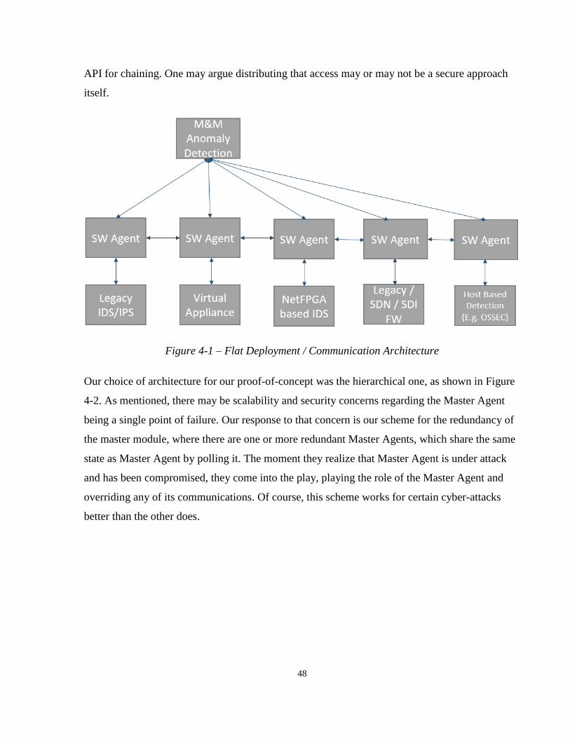
48
API for chaining. One may argue distributing that access may or may not be a secure approach
itself.
Figure 4-1 – Flat Deployment / Communication Architecture
Our choice of architecture for our proof-of-concept was the hierarchical one, as shown in Figure
4-2. As mentioned, there may be scalability and security concerns regarding the Master Agent
being a single point of failure. Our response to that concern is our scheme for the redundancy of
the master module, where there are one or more redundant Master Agents, which share the same
state as Master Agent by polling it. The moment they realize that Master Agent is under attack
and has been compromised, they come into the play, playing the role of the Master Agent and
overriding any of its communications. Of course, this scheme works for certain cyber-attacks
better than the other does.

49
Figure 4-2 – Hierarchical Deployment / Communication Architecture
It is important to note that security at any costs is no good security. In particular, the measures
we establish to secure the system should be cost-effective in terms of the effort spent in them and
the complexities they add to the solution. We do not consider the case of Master Agent’s
compromise common enough, so for our proof-of-concept, while we propose the redundancy
scheme, we did not implement it.
Overall, we established the trade-offs between the design choices we had over the deployment
architecture and implemented the hierarchical scheme without redundancy. Perhaps, there may
be better coordination with the hierarchical model. Of course, that would depend on what
distributed scheme (for the case of the flat deployment) we are comparing our approach with. In
general, distributed algorithms may suffer from greater delays in resolving their state, as the
decision may be not the output of a single / centralized decision maker.
Lastly, it is important to note that we compared the two approaches (hierarchical vs. distributed)
as two alternative methods. We did so by anticipating the trade-offs and analyzing our guesses.
As such, our comparative analysis lacks metrics, and our argument has been purely a high-level
architectural one.

50
4.2 SDI Enabler
In this section, we review the specific parts of the SAVI SDI (Janus) API we used in our
implementation. The parts of the API we used correspond to the two main roles of the SDI
Manger in our platform, which were traffic chaining and distributed blocking (making it the
main module on the feedback loop to the switch).
The chaining for different components differed slightly. In particular, the network interface setup
for our VAs and PAs differed. Our VA implementation is a Virtual Machine (VM) that runs
Snort IDS [57], together with Open vSwitch (OVS) software [58] providing virtual interfaces for
the Snort to use (isolated interfaces for input and output). Consequently, with the help of OVS,
our VA uses only one main network channel to input and output packets.
On the other hand, our PA, which is a Fortigate 111C Unit [59], use two separate network
interfaces for input and output. The interfaces have different MAC addresses, however, they are
invisible to the user, as we used the transparent mode of the inline NIDS. As a result, we needed
different implementations of the chaining API for different kinds of resources we had. This could
be seen as an extensibility concern. However, we believe we have covered the problem space in
this case, as most NIDSes either come in one or two major ports for their main operation (Of
course, also a separate network interface for control).
Our “chain” and “block” are implemented as Python scripts. These scripts can be run on any
device that has a SAVI Client and has been authenticated to use Janus. In particular, these scripts
leverage two fundamental Janus functions:
1- Get path (src, dst): This returns the DPID (Datapath ID) of all the switches that are on
the path from src to dst (which are IP addresses). The path is already determined by
the Janus network controller, based on its path optimization algorithm.
2- Install rule (OpenFlow Rule, DPID): This call installs a given forwarding rule (which
is made up of a match and an action) in a specific switch.

51
For chaining, we install a rule of which action is forwards the matching traffic to the service box
/ VM. For blocking, the action is simply dropping the packet. For the reasons discussed, the
chaining script for the VA and PA slightly differ.
An alternative to using Janus API was to install and utilize our own OpenFlow controller. Such
controller could either work on a dedicated network, a virtual slice or else on an overlay network.
However, Janus had already solved the problem efficient enough, so we choose it for our proof-
*of-concept implementation. We may also consider it a constraint, as we had a PA (Fortigate
111C) that needed to be directly connected to the SAVI network. It is hard to imagine how we
would dynamically chain the PA’s traffic without the use of SAVI’s in-house service chaining
tool.
4.3 Enhanced Security Groups
In this section, we introduce two notions we came up with, namely, Enhanced Security Groups
(ESGs) and Enhanced Security Profiles (ESPs). The first name is a derivative of the “Security
Group”, a concept we discussed in Chapter 2, which is the usual implementation of a hypervisor-
based firewall in the clouds. However, as mentioned, the conventional firewalls have
shortcomings when dealing with new types of attacks. One that is of particular interest to us is
the fact that firewalls tend to be only port-based. This means that they only look at the header of
the packet and not the content / payload.
Realizing this, we decided to extend the concept of firewall to utilize Deep Packet Inspection
(DPI) within it. Using DPI, the possibilities in the packet match space is now infinite (unlike the
case of firewalls, where port number is finite). Therefore, the user definitely needs some help
with detection. For that, we provide the user with a pre-programmed set of DPI rules, which we
call ESP. Another feature of ESPs is to provide a scheme for updating the attack signatures.
Hence, we call the set of DPI rules the ESP, and once its rules are installed in a given NIDS
resource and the NIDS is chained, the rules and the resource together form an ESG, protecting
the VM in a more enhance fashion as opposed to the conventional firewalls.
Using ESGs instead of the regular security groups has performance and network capacity
advantages. This is because using the distributed defense that comes with our ESGs, the blocking
52
of attack will take place at the first ingress gateway router / switch. This reduces the blocking
time, as well as the amount of network usage the attack would have had if it were to be blocked
at the hypervisor level. The drawback of this approach, however, may be a duplication of
responsibility, as the hypervisor firewall overhead may exist regardless of utilizing it or not
(depending on the hypervisor implementation).
As discussed in our scope section, our work does not concern covering many attack types; rather,
we focus on two categories of attacks (DoS and Keyword-based). Since the attack space in terms
of the keyword / pattern-based attack is much bigger, most of our focus is dedicated to DoS
attacks. Each ESP is defined by the DoS sensitivity level it has (which translates to the threshold
in packet count of the same type before flow is detected as an attacking one), as well as
keywords associated with it. We have defined three levels of security sensitivity for DoS attacks:
“High”, “Low”, and “Medium”. These pre-defined levels correspond to different threshold
numbers within the VA and PA. We discuss them as well as the values associated with them in
our evaluation section.
Hence, the user shall specify with their ESP what level of DoS sensitivity they want. This
delegates the responsibility of the trade-offs to the user (as opposed to the cloud manager). As
well, if a user wants, they can dictate the type and size of resource to be used, too. In particular,
they can set their flows to be only run on PA, or VA of different sizes (low, medium, large).
Overall, ESPs represent and granulize certain security parameters that the user is typically
unfamiliar with. This is in line with a side objective of ours, which is user-friendliness. We will
see the manifestation of our ESPs in our UI design subsection.
4.4 Prototype Implementation
In this section, we discuss our proof-of-concept implementation in detail. In particular, we note
the proposed features that were realized in implementation, as well as the components associated
with them. This will prepare the reader for next chapter, which is dedicated to the testing and
measurement.

53
4.4.1 IDS Appliances
In this section, we describe the particular appliances we used in detail. As already mentioned, we
note the used appliances under two major categories throughout our design, VA (Virtual
Appliance) and PA (Physical Appliance).
A VA is cloud hosted, running on a virtual infrastructure (i.e. Virtual Machine (VM)). This
differs from the PA, in that PA runs on a dedicated hardware box. This hardware box may be
made up of hardware specifically designed for DPI, or else it could be dedicated legacy hardware
(e.g. x86) running a proprietary software. For competition-based reasons, the inside is by default
hidden from the users. Another term we may use for the PA is “bare-metal”, which is used for
physical resources that are connected as part of the cloud, but are not virtualized.
Our VA implementation was a combination of Snort Open Source NIDS software running
together with Open vSwitch (OVS), as shown in Figure 4-3. As mentioned, the OVS helps with
providing the by default isolate virtual interfaces for the Snort to listen to (P2 and P3 from the
Figure below). There are static OpenFlow rules in the VM that direct any incoming packet not
destined for the IDS itself to the interfaces that Snort connects them. Hence, in this inline
configuration, Snort acts as a two-port switch, between P2 and P3. P1 is the interface to outside
(typically named “Eth0”). The blue arrows in Figure 4-3 represent the static OpenFlow rules that
steer the relevant inspection traffic to the Snort, and from the output of Snort (P3), back to P1. If
a packet has been successfully inspected and not blocked, it will be then sent from the VA to the
destination node.

54
Figure 4-3 - VA Implementation Using Virtual Machine including Snort and OVS – Note the
direction of traffic
It is worth noting that our implementation of VA was not transparent, as it involved changing the
MAC address of the packet before sending it out through P1. The reason for this was a default
Firewall rule implemented in our hypervisors, that a packet going out from a VM should have
the source MAC address of that VM. This is to ensure no spoofing occurs inside the network.
We preferred not to touch that default rule, as it could lead to compromise of other VMs. Hence,
unlike our PA, our VA implementation was not transparent, as both end-hosts would see the
MAC address of the VA IDS in their packets. One may argue that this may help potential
attackers in identifying the IDS to attack it directly. We traded-off this risk with the hypervisor
firewall concern we discussed. As we will discuss in the next subsections, this also had
implications in terms of load balancing for the VAs.
The alternatives we considered for the implementation resources include Snort, Fortigate 111C
unit, Bro IDS, and custom NetFPGA-based NIDS. We believe Snort was a good choice for VA,
as it is one of the best well-written and most popular Open Source IDS software [60]. It
55
popularity implies that it fits well for abstraction and generalization of NIDS functions. As well,
it covers most attack types and has a flexible rule system, which is easy to use and program
remotely. Snort has been well documented and has various configuration modes and settings,
which we found helpful (e.g. can use it for both tap and inline). We were able to easily make
copies of the VA by storing its VM Image into our OpenStack image registry module and
spawning VMs based on that later on.
Likewise, we found Fortinet Fortigate 111C a good representative of the physical NIDS boxes.
In particular, Fortinet has been known to an industry leader in terms of network security
solutions over the recent decade or so (standing along other major players such as Cisco) [61].
The Fortigate 111C had all that was needed, including an SSH interface to program remotely,
and had relatively lower processing delay.
4.4.2 Component Placement
We introduced our high-level components in Chapter 3. In particular, we introduced the Security
Master Agent / Controller and a set of SW Agents for security resources, one per each NIDS
type. However, there are various ways for these components to be realized in implementation.
In this subsection, we discuss two main component placement considerations. The first is the
placement of SW and FW Agents, and the second is about NIDS resource placement and its
impact on delay.
In hierarchical deployment, the SW Agents, they may be implemented as part of the Master
Agent / Security Controller’s, placing it in the VM associated with it. This would not work for
the flat deployment architecture, as each SW Agent needs to be implemented in a separate VM
(since trust is not centralized anywhere). As already mentioned, we chose the hierarchical
deployment. Due to the reduced performance overhead, we chose to implement the SW Agents
inside the Master Agent. In particular, as we will discuss in a later subsection, the SW Agents are
implemented as scripts inside the Master Agent.
In terms of NIDS placement, our cloud platform (SAVI) has several edges, each edge having
several Agents, which are the hypervisor servers. As we will show in Chapter 5, the placement of
the NIDS has a considerable impact on the round-trip time. Of course, the placement argument
56
only applies to the VAs, as the PA cannot be placed (on-demand) with as much flexibility. For
our PA’s case, which was static, we used a switch near a SAVI Smart Edge node located at the
University of Toronto to connect the Fortigate 111C unit to the SAVI network.
For the VAs, however, we decided to place them dynamically and as close as possible to the
server we are protecting. We implemented a simple greedy algorithm that attempts to place the
NIDS in the same agent / hypervisor as the server we are protecting. Of course, a better
alternative would have been to come up with an algorithm that considers the whole default path.
4.4.3 Configuration API
Our NIDS configuration API is closely related to Enhanced Security Groups (ESGs). This API
essentially communicates what is needed there in the IDS. We ensured to design a transparent
API, in that our API requires the user to have no knowledge of the underlying platform. All they
provide is their security requirements (through the ESPs), which the Master Security Controller
(Master Agent) realizes them by applying the configuration API.
Our API is RESTful, and hence enjoys the advantages such as interoperability, scalability, and
familiarity (what it exposes is known ahead of time) [62]. As well, it is stateless, in that in only
functions based on the sequence of the input it gets, not storing anything about any IDS from the
past. Perhaps, that also contributes to ensuring the privacy of the cloud users, as we do not record
what levels of security they have had at a particular point in time.
4.4.4 Master Coordination Agent
The title of this subsection is yet another name for our Master Agent / Master Security
Controller. Perhaps we liked using different names for it to make it as general as possible. This
module has various responsibilities, such as implementing the communicated ESPs into ESGs
(through leveraging its SW agents, which are scripts inside of it), logging and tracking security
events (e.g. detection / FW action by a FW agent), and logging resource CPU and bandwidth
utilizations.

57
As well, we used it as the HTTPS server that the trusted users utilize in order to communicate
their ESPs. If we wanted to be safer, we could have perhaps separated this server from the
Master Module. However, there trade-off is increased delay (both processing and network delay
overhead are added). Given that spawning VA resources may take time in order of minutes, we
did not desire to add any further delay. Perhaps one may feel that the field of security is all about
security and performance trade-offs [63].
For similar performance reasons, we delegated the IAM (Identity and Access Management) to
SAVI’s OpenStack-based IAM [64]. This IAM is a secure system designed particularly to be
scalable. As well, we added a bit of Access Control on top of it ourselves, in that we decided
who would know the specific URLs has to access the system. Of course, our implementation was
rather small in scale, as it only had a single admin account.
For ease of use, increasing portability, and easy migration, we implemented the Master Agent
and the User Webserver inside a single Docker container [65]. We initially took a container that
had the SAVI client and Janus API built in and added the rest of the features of the Master Agent
on that infrastructure.
Figure 4-4 describes the components of Master Agent in detail. In particular, the user, which has
already authenticated through SAVI and has access to SAVI’s internal IP, may access the server.
The RC1 (Resource Controller 1) and RC2 are the SW Agents, named in this Figure following
the naming convention of the Software Defined Infrastructure (SDI). They are realized through
scripts, which is discussed in the next section. The Master Agent essentially parses the
requirements of the ESPs and passes the info the corresponding SW Agents / Resource
Controllers to implement them.

58
Figure 4-4 – Detailed Components of Master Agent
The ESP Repository is essentially a set of files defining the ESPs. We did not implement this as
a proper database, as we did not need that for our scale of attack knowledge. However, we do
propose that for bigger enterprise systems that may have many ESPs, it might make sense to
implement a dedicated database. This would also help with any ESP / attack definition updating
scheme, which our implementation does not include.
4.4.5 Software Configuration Agents
Our Software Configuration Agents, which have also introduced as SW Agents, are the key
backend components that enable the realization of our interoperable NIDS configuration protocol
and our ESPs in the actual security resources. For security, they utilize an SSH-based interface,
directly and securely running commands within the terminal of the machine itself. They are
indeed among the most trusted and crucial components of the design.
In our implementation, they happen to be located together with the ESP Repository in the Master
Agent. Their implementations are set of Bash and Expect scripts, that perform the setting
configuration remotely on the NIDSes, whether PA or VA. As mentioned previously, use of SSH
is not a requirement, and SW agents can be implemented for any NIDS that would allow some
form of secure communication to edit the security settings in it remotely.

59
4.4.6 Load Balancer
We performed an in-depth analysis of NIDS Load balancing schemes, which we summarize in
this subsection. We found that in our case, Load Balancing, Resource Scheduling, and Service
Chaining are closely related. In particular, Load Balancer (LB) implementation depends on the
resource sharing policy, and its implementation affects the resource scheduling. As well, to
enable an LB, service chaining is needed one way or another. Our idea is to combine these into a
logical entity that does all the three.
Whether such combination is a good idea or not depends on how the control architecture
distributes its responsibilities. In particular, it may be centralized (logically and/or physical) or
distributed (to reduce / distribute points of failure). We reviewed various schemes and compared
them in order to make a proper design decision.
4.4.6.1 Distributed Scheme
The first alternative, as shown in Figure 4-5, is the distributed LB architecture. In this scheme,
we divide the user flows among a set of load balancer modules. Each VA pool is dedicated to
one LB, which is assigned a particular security profile and set of requirements (e.g. delay). We
should note that each VA (and our PA) is only capable of handling one security profile at any
given point in time. Hence, we need to consider both bandwidth and delay requirements when
coming up with the VA pools.
Figure 4-5 – Distributed Load Balancing Scheme

60
We implemented this scheme using an OVS based VM. In particular, we used a feature of
OpenFlow 1.1, where a rule’s action can be assigned as a simple round robin or hash-based
selection over a set of actions [66]. Its integration with OVS, however, was recent at the time of
our experimentation and we had to fix an OVS bug to make it work.
The chaining of the traffic from the LB to the NIDS could be done in different ways. There was
an issue with the default hypervisor’s firewall, where packets leaving a VM should have the
source MAC address of that VM in order to prevent L2 spoofing. For that, instead of direct
chaining, we experimented mainly with VXLAN (Virtual Extensible LAN) overlay connections,
from the LB to the NIDS, where the load balancing is done by distributing the packets over the
VXLAN’s virtual interfaces of OVS. This worked well for both forward and reverse path load
balancing.
Another scheme we tried in our forward load balancing was to do it by changing the source and
destination MAC addresses. This works well for the forward path, as the ultimate MAC
destination (of the server being protected) is known in advance. As well, this works well with our
architecture since we do not have packets of user flows not going to the same server end node
passing through the same NIDS (i.e. each NIDS is tied to a specific server it protects). However,
this scheme does not work for reverse / response path load balancing. The reason is, in the
response path, we are not dealing with a single destination MAC address (as user MAC
addresses are different), and having a way to figure out what MAC address to translate to is not
easy. One possible way is to utilize the overlay for the response path.
We combined the two approaches mentioned in the last two paragraphs. In particular, we used
MAC address swapping for the forward path and overlay based load balancing for the response
path. Utilizing this L2 / Data path based load balancing, we achieved fast decision making (for
the forward path).
The most important factor in load balancing, for us, is resource utilization. We could have each
LB module collect resource utilization data (by either leveraging SAVI M&M or a dedicated
Data Acquisition System). However, this may result in the same information being processed
several times, which is not as efficient as having a centralized decision making module.

61
As well, we had certain concerns regarding this proposed scheme of ours. In this scheme, we
always need multiple LBs to avoid bottlenecks / single point of failure. As well, we need to
categorize LBs based on security requirements. However, even with these, each LB could still be
a bottleneck for its given category of user flows. More importantly, there is extra delay caused by
the LB switches because of their addition to the path.
4.4.6.2 Centralized Flow Assigner
Another scheme we implemented and chose for our final design was a decision centralization-
based one. The main idea was that instead of using extra LB modules, we have the load
balancing buried in the initial service chaining, updated at times based on security resource
utilization, if there need be. This scheme is depicted in Figure 4-6.
Figure 4-6 – Centralized Load Balancing Scheme
We found this scheme easier to experiment ideas with, as the algorithm was implemented in a
central location than in a number of LB modules. There is no additional delay or any additional
bottlenecks introduced in this approach (as opposed to the distributed one). The only challenge in
this approach is reassigning a flow to a different resource without disruption, should a flow grow
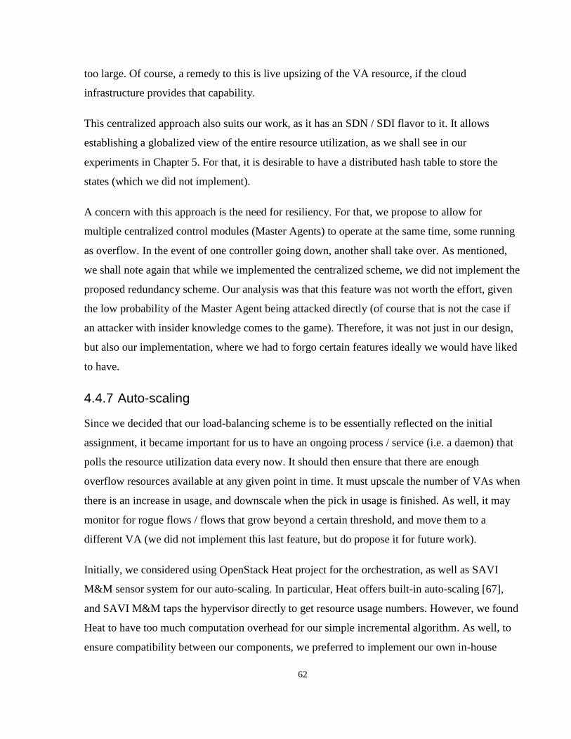
62
too large. Of course, a remedy to this is live upsizing of the VA resource, if the cloud
infrastructure provides that capability.
This centralized approach also suits our work, as it has an SDN / SDI flavor to it. It allows
establishing a globalized view of the entire resource utilization, as we shall see in our
experiments in Chapter 5. For that, it is desirable to have a distributed hash table to store the
states (which we did not implement).
A concern with this approach is the need for resiliency. For that, we propose to allow for
multiple centralized control modules (Master Agents) to operate at the same time, some running
as overflow. In the event of one controller going down, another shall take over. As mentioned,
we shall note again that while we implemented the centralized scheme, we did not implement the
proposed redundancy scheme. Our analysis was that this feature was not worth the effort, given
the low probability of the Master Agent being attacked directly (of course that is not the case if
an attacker with insider knowledge comes to the game). Therefore, it was not just in our design,
but also our implementation, where we had to forgo certain features ideally we would have liked
to have.
4.4.7 Auto-scaling
Since we decided that our load-balancing scheme is to be essentially reflected on the initial
assignment, it became important for us to have an ongoing process / service (i.e. a daemon) that
polls the resource utilization data every now. It should then ensure that there are enough
overflow resources available at any given point in time. It must upscale the number of VAs when
there is an increase in usage, and downscale when the pick in usage is finished. As well, it may
monitor for rogue flows / flows that grow beyond a certain threshold, and move them to a
different VA (we did not implement this last feature, but do propose it for future work).
Initially, we considered using OpenStack Heat project for the orchestration, as well as SAVI
M&M sensor system for our auto-scaling. In particular, Heat offers built-in auto-scaling [67],
and SAVI M&M taps the hypervisor directly to get resource usage numbers. However, we found
Heat to have too much computation overhead for our simple incremental algorithm. As well, to
ensure compatibility between our components, we preferred to implement our own in-house

63
orchestration tool, which utilizes the Nova client that we included in the Master Agent’s Docker
container. Similarly, we found that SAVI M&M tends to break often, as it is a research solution
with no production level resiliency and support. Hence, we found it more time-efficient to
implement our own data acquisition system than spending time to reverse engineer and modify
SAVI M&M to become more reliable.
The most important factor for our auto-scaling system is the number of overflow VA resources
we have at any given time. We developed a program that regularly polls the utilization data, and
based on, decides if there needs to be upscaling, no action, or downscaling. Our up and down
scaling consists of a single resource addition or removal.
We measured that our VAs could take up to 2 minutes to boot up and get running. This
important, as it reflects the importance of having enough number of VAs in advance. A feature
we did not implement, but do propose is the potential use of ROC (Rate of Change) of the
number and bandwidth of user flows. Another is to perform historical analysis to customize the
increments and/or prepare enough overflow resources in advance to deal with traffic surges. In
any case, our simpler greedy auto-scaling scheme works fine for a proof-of-concept.
In our implemented algorithm, the data points we use are one sample per minute, reported by the
VAs themselves (by the SW Agent in the case of the PA) to the Master Agent (by accessing the
system via SSH in and writing to a log file). As we shall see in Chapter 5, we could have used
either Bandwidth or CPU Utilization. However, we chose CPU Utilization, as we found CPU to
be the particular bottleneck, and its usages percentage has a well-known upper bound (i.e.
100%). Our auto-scaling script is called periodically (roughly about once a half hour), as well as
every time a flow is assigned, to see if we need to add more overflow VA resources or not. It
works by averaging samples to see if they go below or above a certain threshold (10% for
downscaling, 70% for upscaling).
4.4.8 Web User Interface
This subsection describes the Web User Interface (UI) that the trusted users of the cloud platform
have access in order to configure their user flows and NIDSes. As mentioned, in our

64
implementation, the backend is located within the Master Agent’s VM, but could have been
separated for increased security (at the cost of extra configuration delay)).
This UI essentially realizes the requirements of Enhanced Security Profiles, which translate to
the NIDS requirements by the Master and SW Agents later on. As mentioned in Figure 4-4, we
utilize code written in Node.js for the backend, due to its simplicity in implementation
(behavioral JavaScript), as well as the significant speed of prototyping, which is due to its rich
built-in libraries and frameworks such as Express [68]. For example, switching our initial HTTP
to HTTPS required changing less than 10 lines of code.
As mentioned, our server is HTTPS, to provide the users with confidentiality. However, we did
not anticipate or design a particular certificate distribution scheme, since we find outside the
scope of our work. This is similar to key distribution for the VM’s accesses, which we delegated
to SAVI IAM and Key Management Systems (which themselves are extensions on up of
OpenStack project).
Another reason we picked Node.js was for its capability of working asynchronously, which is a
scalable choice for the server. For increased security, the server required SAVI Login for
authentication (for which, the server included a built-in SAVI client). For the client-side pages,
the Bootstrap [69] JavaScript framework was used. As part of that, we took advantage of
MaxCDN Content Distribution Network, which caches the Bootstrap script library.
Screenshots of our GUI are shown in Figures 15-18. The first page shows the sign in page, which
a SAVI user can login with their SAVI credentials. The second page shows the list of their VMs
within the specific tenant and region they logged into along with their IP addresses, which could
later be used for chaining. The third page is where ESPs could be defined and applied. The last
page is where traffic-chaining requests are made. To chain all the traffic going and coming to a
VM, the chaining can be made between the gateway switch and the VM.
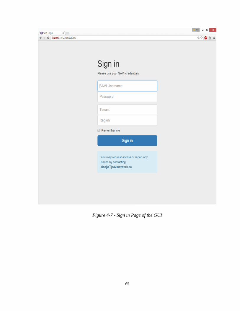
65
Figure 4-7 - Sign in Page of the GUI
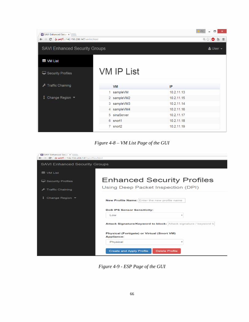
66
Figure 4-8 – VM List Page of the GUI
Figure 4-9 - ESP Page of the GUI

67
Figure 4-10 – Chaining Page of the GUI
The ESPs defined specify three parameters: Resource Type, DoS Threshold, and Attack
Signature. Resource Type could be either "Physical" or "Virtual", Physical meaning the Fortigate
111C unit, while Virtual refers to the Snort-based Virtual Appliance (VA). DoS Threshold could
be "Low", "Medium", or "High". These three levels were translated to specific threshold values
of 50000, 5000, 1000 TCP Syn packet/second (for the VA’s case, for the PA the threshold
measure is slightly different). The Attack Signature field contains the signature of a specific
attack to block. The ESP fields were communicated and stored in JSON format.
68
Chapter 5 Testing and Evaluation
In this chapter, we present our testing and evaluation, which demonstrates the extent to which we
have achieved our objectives. We first begin by going over the functional verifications we
performed to ensure our design performs all the necessary functions. Then, we discuss the
parameters of interest, which work similar to figures of merit for us. We follow by talking about
the specific tests we have performed to measure scalability, detection accuracy, information
integrity, and finally an analysis on our interoperability. These tests will provide us enough
evidence to make our conclusions in our fifth and final chapter.
5.1 Functional Verification
Our functional verification of the prototype consisted of several parts. First, we ensured the
chaining worked. To check that, we performed chaining for both the PA and VA using the SDI
Enabler. To do so, we would spawn three VMs, one user host, another for the middleman (which
is the NIDS VM), and a third one representing the server on the cloud. We would then call our
Janus script, which performs the chaining, providing the internal IP addresses of the three
aforementioned VMs as parameters. The script would then go through all the switches on the
path, ensure appropriate forwarding rules are put there so that the traffic would first go to the
middleman IDS, and from there to the server, as well as the reverse.
Once the chaining is done, we used a typical network debugging and packet displaying tool
called TCPDUMP [70]. With TCPDUMP, we could choose just to see the header, or the entire
packet, as desired. We used this tool to verify that the packets are indeed chaining through the
NIDS, as shown in Figure 5-1. In particular, we should note the difference in the difference of
the MAC address of the user (from the server’s perspective) before and after chaining, as well as
the difference in time for the packet to go through. The former stems from our IDSes lack of
transparency from the server side. However, the IDS remains transparent to the user host.

69
Figure 5-1 – Verification of Chaining Using Ping and TCPDUMP (above is for chained, below
is before chaining)
After that, we needed to check if the IDS worked. To do so, it had to pass two basic tests: It can
pass a healthy packet, and drop one unhealthy (i.e. defined as an attack) packet. For the test
setup, we created two virtual machines in EDGE-TR-1 of SAVI Testbed. The first virtual
machine was to act as attacker machine, utilizing hping3 [71] to launch TCP Syn Flood attacks.
The second virtual machine was the victim machine, utilizing Speedometer utility [72] to display
the amount of ingress traffic.
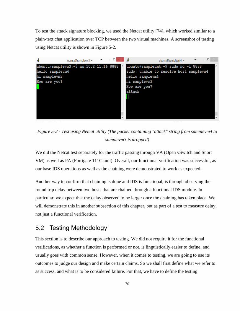
70
To test the attack signature blocking, we used the Netcat utility [74], which worked similar to a
plain-text chat application over TCP between the two virtual machines. A screenshot of testing
using Netcat utility is shown in Figure 5-2.
Figure 5-2 - Test using Netcat utility (The packet containing "attack" string from samplevm4 to
samplevm3 is dropped)
We did the Netcat test separately for the traffic passing through VA (Open vSwitch and Snort
VM) as well as PA (Fortigate 111C unit). Overall, our functional verification was successful, as
our base IDS operations as well as the chaining were demonstrated to work as expected.
Another way to confirm that chaining is done and IDS is functional, is through observing the
round trip delay between two hosts that are chained through a functional IDS module. In
particular, we expect that the delay observed to be larger once the chaining has taken place. We
will demonstrate this in another subsection of this chapter, but as part of a test to measure delay,
not just a functional verification.
5.2 Testing Methodology
This section is to describe our approach to testing. We did not require it for the functional
verifications, as whether a function is performed or not, is linguistically easier to define, and
usually goes with common sense. However, when it comes to testing, we are going to use its
outcomes to judge our design and make certain claims. So we shall first define what we refer to
as success, and what is to be considered failure. For that, we have to define the testing
71
dimensions, which we discuss as part of our parameters of interest below. First, let’s briefly
recall our problem and its scope, so that we ensure our tests are going to make sense for them.
In particular, it is vital to note that the actual “security” of the cloud, or “how secure is it” is hard
to be quantified or even defined in a quantitative way. For example, one measure may be “risk”,
which is “cost of compromise” multiplied by “probability or frequency of it happening”.
However, digging deep into that, we have to deal with lots of factors that are out of the scope of
our work. It is jokingly said that an ideally secure system is a system that has no connection to
outside whatsoever (including any interactions with a human user), in which case, is of no use.
We are not going to be testing with a diverse set of traffic. Rather, we would be using a few
known attacks, such as “DoS”, “DDoS”, and “Attack Keyword or RegEx Pattern”. Together,
these cover two proposed categories of attacks commonly detected by signature-based IDSes:
1- The category of attacks that involve a pattern or packet to be repeated a certain number of
times. This category is usually detectable using header info alone.
2- The second category covers the mere existence of a certain keyword or pattern within the
payload of any given packet. For this category, we definitely require DPI, as the data /
payload of packet shall be investigated. The IDS, obviously, does not work on the
encrypted payloads (unless militarizing it to drop any unknown packet).
These two proposed categories, combined, represents almost any attack that can be detected by
an IDS. If both categories looked at the header and the payload, then the second one would have
been a special case of the first one. However, as mentioned, that is not the case, as one tends to
involve mostly the header info, while in the other the payload has to go through complete
inspection.
5.2.1 Parameters of Interest
The parameters that we base upon our tests are important, as they are a derivative of our testing
methodology. Therefore, in order to have a correct methodology, one has to be looking at the
right parameters. An analogy to this would be the selection of variable as features in machine
learning, only the variables that make sense and directly correlate with the objectives are to be

72
chosen. The particular “learning” we try to achieve is to see how much our design actually
works, and to what extent it meets its objectives.
As mentioned in the last subsection, our design has performed all of the functions we manifested
for it. Now, in order to see how well it has met them, we will look at the following parameters:
1- Detection Time: We define this as the time it takes for the attack to be detected from the
time it is launched. While we cannot control the detection time of our individual IDS
modules (VA or PA), we argue will attempt to measure whether leveraging SDI to
smartly place the modules helps us to reduce this detection time. This could, in turn,
provide a better defense / attack mitigation.
2- Relative Delay Overhead: This is a measure of the added delay because of the added
security. It consists of the DPI delay as well as the extra path delay. We can measure at
least the sum of these two, and see what factors may contribute to the sum.
3- Scalability: We define our scalability measure as the ratio of the growth rate of the
computing and networking resources or resource utilization versus the inspection
throughput. In particular, we will be commenting on the slope of the best fit line (Least
Square Method).
We could also look at the number of flows or number of (identical / unit) resources used.
The latter involves specifying some simplifying assumptions, e.g. having weights for
different sizes of VAs and the PA.
4- Detection Accuracy: We define this parameter for a set of packets, for varying degree of
attack to benign traffic mixes, and we intend to measure the detection and attack
penetration ratios.
5- Information Integrity: This measure is similar to detection accuracy, except this is the
ratio of the information in the payload of the benign packets received safely and in order
(i.e. not dropped or arriving out of order).

73
6- Performance: In our case, we can define it by looking at the throughput and delay. The
throughput performance is best understood from the scalability of our platform (its actual
value matters less, as we are not competing with the production systems), while the delay
is best measured by the relative delay concept already discussed.
7- Overall resource utilization: Could be defined by subtracting on the ratio of the time that
a unit is unused. If we wanted to be further specific, we could also look at the ratio of
utilization, as well (i.e. to ensure a unit is not marked as “utilized” while it’s under-
utilized (e.g. single inactive user flow)).
Overall, these parameters of interest help us document and discuss the process as well as the
outcome of our tests, and further aid us in our overall evaluation of our design. Table 5-1 lists the
testing parameters.
Parameter Name Exact Measure
Detection Time Detection Time in ms (milliseconds)
Relative Delay Overhead RTT difference (to baseline) in ms
Scalability (horizontal) Ratio of rate of resource growth (number of
resources) vs. growth in demand (mbps)
Detection Accuracy Ratio of attack packets penetrating (for a given
attack)
Information Integrity Ratio of non-attack packets safely arriving
Overall Resource Utilization Ratio of resource utilization (CPU usage) over
all deployed resources (over a period of time)
Table 5-1 – Chosen Testing Parameters
74
5.3 Test for Detection Time
In this test, the testing scheme is similar to that of our functional verification. In particular, we
have three VMs, all in the same network, one user host VM, another the IDS (VA or PA), and
one server host VM. The traffic of user to server and reverse is chained through the IDS. We
now measure how long it takes the IDS to detect attacks. For the attacks, we will have two, each
representing one of the major attack categories described earlier. In particular, one DoS attack
(TCP Syn Flood), representing the DoS category (i.e. attacks that require counting) and another
representing the attacks of which signature is mere existence of a keyword or regex pattern.
We performed the detection time test for both VA and PA. However, we are more interested in
the case of the VA, because we get some options in terms of the placement of the VM (from a
specific set of hypervisor servers). Hence, we can play with the placement of the IDS VM to see
to what extent its placement makes a difference.
First, we performed the test for a typical / representative case of a single IDS doing detection.
We appreciate that single experiment evidence is not as representative as a repeated test over
time, so we did the latter as well, but first, we discuss the individual case in order to get a better
intuition on the DoS inspection traffic we are dealing with.
As mentioned in chapter 4, the security profile for our IDSes come with three different DoS
threshold levels. This leveling, while reducing the granularity, is helpful to the users with less
security technical knowledge in configuring their profiles. In specific, they have to choose
between “low”, “medium”, and “high” security sensitivity / levels. In this way, we also delegate
the choice of the possible trade-offs (e.g. detection accuracy vs. how secure the system is) to the
user. For the VA, we defined our Snort to have a 10 second DoS (Syn Attack) detection
threshold window (i.e. the counter’s reset period is 10 seconds), while Fortigate 111C unit’s
threshold period is fixed at a minute. However, it seems that it is ultimately the rate that matters,
as the detection resources do not take the whole window for their detection to kick in.
Figures 21 to 23 demonstrate the detection time measurements we did for our implemented VA,
while Figures 24 to 26 are for the case of PA. In particular, each graph indicates the Speedometer
reading of the server side. The initial peak is the point attack starts arriving (E.g. almost mid-way
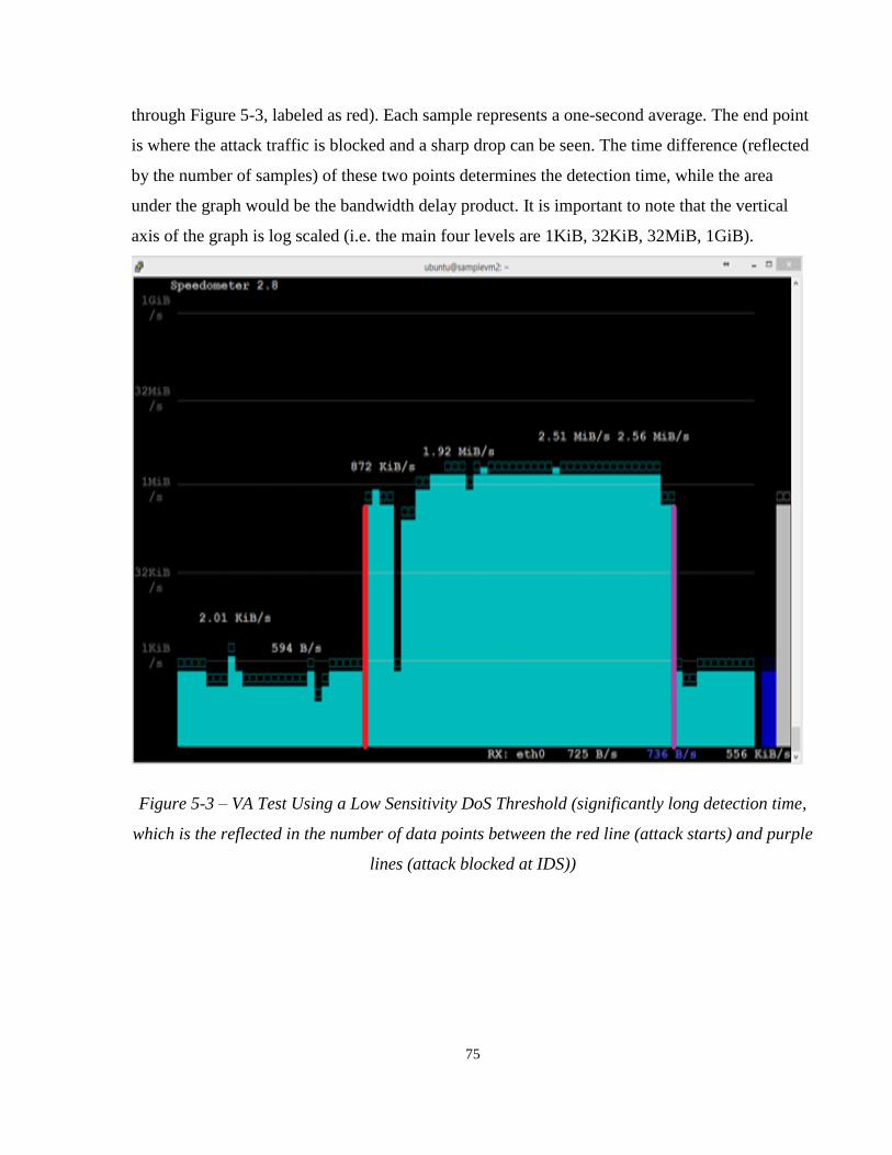
75
through Figure 5-3, labeled as red). Each sample represents a one-second average. The end point
is where the attack traffic is blocked and a sharp drop can be seen. The time difference (reflected
by the number of samples) of these two points determines the detection time, while the area
under the graph would be the bandwidth delay product. It is important to note that the vertical
axis of the graph is log scaled (i.e. the main four levels are 1KiB, 32KiB, 32MiB, 1GiB).
Figure 5-3 – VA Test Using a Low Sensitivity DoS Threshold (significantly long detection time,
which is the reflected in the number of data points between the red line (attack starts) and purple
lines (attack blocked at IDS))

76
Figure 5-4 - VA Test Using a Medium Sensitivity DoS Threshold (less detection time compared
to "Low" setting)
Figure 5-5 - VA Test Using a High Sensitivity DoS Threshold (as if the attack traffic hardly ever
gets to the victim VM)
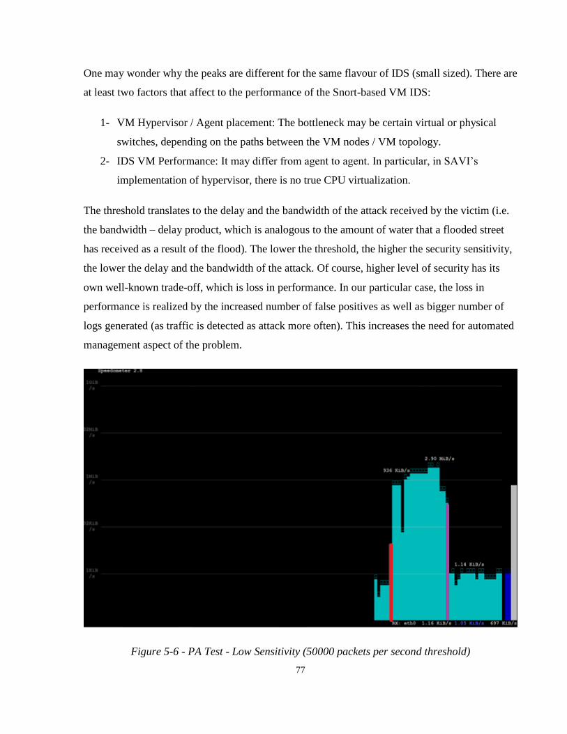
77
One may wonder why the peaks are different for the same flavour of IDS (small sized). There are
at least two factors that affect to the performance of the Snort-based VM IDS:
1- VM Hypervisor / Agent placement: The bottleneck may be certain virtual or physical
switches, depending on the paths between the VM nodes / VM topology.
2- IDS VM Performance: It may differ from agent to agent. In particular, in SAVI’s
implementation of hypervisor, there is no true CPU virtualization.
The threshold translates to the delay and the bandwidth of the attack received by the victim (i.e.
the bandwidth – delay product, which is analogous to the amount of water that a flooded street
has received as a result of the flood). The lower the threshold, the higher the security sensitivity,
the lower the delay and the bandwidth of the attack. Of course, higher level of security has its
own well-known trade-off, which is loss in performance. In our particular case, the loss in
performance is realized by the increased number of false positives as well as bigger number of
logs generated (as traffic is detected as attack more often). This increases the need for automated
management aspect of the problem.
Figure 5-6 - PA Test - Low Sensitivity (50000 packets per second threshold)
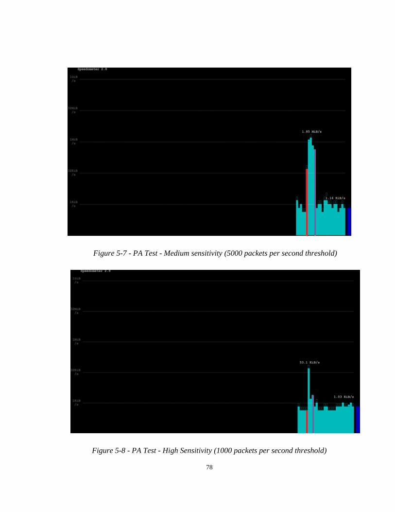
78
Figure 5-7 - PA Test - Medium sensitivity (5000 packets per second threshold)
Figure 5-8 - PA Test - High Sensitivity (1000 packets per second threshold)

79
Rather than fixed attack rates, we used flooding for our experiments, which we observed up to
3.5 MiB/s (Mega Bytes per second) attack traffic being felt at the victim. We used the tool
Hping3 to generate these attacks, and used the tool Speedometer to display the traffic [72]. We
used the default sampling rate of Speedometer, which is one sample per second.
The point of this anecdotal evidence here is to help the reader appreciate the amount of traffic
that go through the system before the detection. This matters a lot, as such transitional traffic,
depending on its size, may be strong enough to disable all network operations for a significant
amount of time (even after already detected). Hence, as we will discuss in the next section,
strategic placement of IDS to reduce the detection time matters. In particular, the DoS traffic
may be measured by its bandwidth – delay product, which is a measure of how much data is on
the network being delivered. By reducing the delay, we reduce the amount of attack traffic
transitionally residing on the network before being detected and mitigated. As well, we put care
into separating control and inspection network channels; otherwise, this could have been
troublesome for the detection entities to coordinate with one another.
We do not discuss the case of keyword detection, as we believe the primary factor in the
detection time of such attacks is the time spent for (as low as) a single packet to traverse through
a network to the detection resource. This the case because there is no counting, thresholding, or
further processing on a group of packets is needed to detect these type of attack, and we believe
the detection of a single packet is almost instant (at least by human standards, of course, it is
many CPU cycles). For the measurement of such traversing to be representative, we would have
to model cloud network traffic and queuing times, perhaps using a probabilistic model, which is
out of the scope of our work.
As discussed, in general, we expect a better performance from the PA. However, this is primarily
manifested in the reduced processing delay, reflected in the round trip time, which is discussed in
the next section. As for the detection time itself, the PA seems to be slightly more efficient than
our VA implementation (which is OVS and Snort based VM).
Besides the anecdotal evidence, we repeated the VA detection time experiment for different
sensitivity levels (Low, Medium, and High) over approximately 20 hours. In particular, we had
the attacker log the attack initiation time, and the IDSes log the detection time. The Firewall

80
feedback functionality was disabled so that the attack could go happen repeatedly. Different
attacks took different lengths of time, so the actual number of attacks differ. In particular, for
high, medium, and low security levels, we had 1890, 991, and 573 attacks. Table 5-2 summarizes
our findings.
IDS Sensitivity Average Min Max Ratio of Attacks
Not Detected
High 8.451 sec 5.216 15.044 sec 0%
Medium 23.310 sec 22.349 sec 25.557 sec 0%
Low 38.827 sec 38.462 sec 39.432 sec 21.12%
Table 5-2 – Summary of the Experiment Measuring the Detection Time of Different Security
Sensitivities
These results justify our choices of the security levels, as one can deduct the trade-offs, the major
one being how much bandwidth-delay product is the platform gets exposed to versus the
accuracy of the detection platform.
5.4 Test for Relative Delay Measurement
This test was not only to measure the relative delay, but also, to see whether the placement of
IDS matters or not, and if so, how could that be utilized to increase the performance of the
platform. Delay matters a lot. Together with bandwidth, it is considered one of the most
fundamental performance characteristic of any packet delivery network [73].
For this test, we considered several scenarios:
1- Scenario 1: The IDS VA is in the same hypervisor as the server being protected.
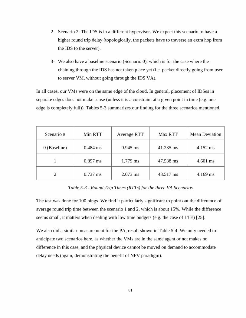
81
2- Scenario 2: The IDS is in a different hypervisor. We expect this scenario to have a
higher round trip delay (topologically, the packets have to traverse an extra hop from
the IDS to the server).
3- We also have a baseline scenario (Scenario 0), which is for the case where the
chaining through the IDS has not taken place yet (i.e. packet directly going from user
to server VM, without going through the IDS VA).
In all cases, our VMs were on the same edge of the cloud. In general, placement of IDSes in
separate edges does not make sense (unless it is a constraint at a given point in time (e.g. one
edge is completely full)). Tables 5-3 summarizes our finding for the three scenarios mentioned.
Scenario # Min RTT Average RTT Max RTT Mean Deviation
0 (Baseline) 0.484 ms 0.945 ms 41.235 ms 4.152 ms
1 0.897 ms 1.779 ms 47.538 ms 4.601 ms
2 0.737 ms 2.073 ms 43.517 ms 4.169 ms
Table 5-3 - Round Trip Times (RTTs) for the three VA Scenarios
The test was done for 100 pings. We find it particularly significant to point out the difference of
average round trip time between the scenario 1 and 2, which is about 15%. While the difference
seems small, it matters when dealing with low time budgets (e.g. the case of LTE) [25].
We also did a similar measurement for the PA, result shown in Table 5-4. We only needed to
anticipate two scenarios here, as whether the VMs are in the same agent or not makes no
difference in this case, and the physical device cannot be moved on demand to accommodate
delay needs (again, demonstrating the benefit of NFV paradigm).

82
Scenario # Min RTT Average RTT Max RTT Mean Deviation
Baseline 0.425 ms 0.639 ms 34.125 ms 4.112 ms
Chained 0.719 ms 1.549 ms 35.595 ms 4.588 ms
Table 5-4 - Round Trip Times (RTTs) for the two PA Scenarios
As one may observe, the overall round trip time using the PA is the best (1.549ms). As expected,
this stems from the lower processing time that the PAs typically have. In all test cases, since
there was no DoS attack involved, we had zero packet loss, which demonstrates our system to be
reliable in terms of information integrity.
Another observation is that there may seem to be a considerable variance in the packet delay of
our network. This stems from the fact that SDI’s chaining is implemented using SDN /
OpenFlow under the hood, which requires the first packet to be forwarded to the controller. In
fact, that very first packet is the one causing the max RTT (35.595ms in Table 5-4 and 43.517ms
in Table 5-3). As well, there may be a small amount of variance added by the IDS’s deep
processing of the packet, resulting in some packets passing through faster or slower than the
others.
While the Scenario 1 has a higher mean deviation than Scenario 2, the difference is negligible
(roughly within 10% of each other). If we exclude the first packet, the mean deviation for the
Scenario 0 decreases by roughly a factor of 50. This may question our choice of testing with
merely 100 ping attempts. However, we verified our assumption that it is the first packet of
which delay heavily deviates, the rest of delays are much closer to one another in distribution. In
fact, use of 100 pings emphasizes the importance of the first packet delay, especially for the case
of flows that are small in size / bandwidth yet are delay sensitive (e.g. voice samples for
conversation). Depending on how forgetful the OpenFlow based switches are, the first packet
delay event may occur regularly, often enough to consider the first packet delay performance. In
our case, it occurs 1% of the time, and yet it introduces a significant change in the delay
distribution. Further discussion of OpenFlow implementation details is outside the scope of our
work, we left it mostly to SAVI Janus.
83
Another aspect of concern is that the load balancing scheme choice has an impact on the relative
delay. In our case, we did not use middleman load balancers and did our load balancing
distributed at the switches, guided by the central controller / master agent. Had we gone with an
implementation where the decision making was distributed (as discussed in Chapter 4), we
would have had additional delays. We estimate the additional delay may have been as high as 0.5
to 1ms, depending on the topology and hypervisor location.
5.5 Test for Scalability
As we mentioned in our parameters of interest section, perhaps a good measure for scalability is
through showing some linear form of growth of resources per input / demand unit. We further
claim that such linearity could be shown through an incremental analysis, where we show how
going from one level / step to another, the increase will continue to be linear (similar to a proof
by induction, except we do not intend to be that mathematical in argument here).
As discussed, the scalability could be horizontal and vertical, and the linearity could be measured
against several input parameters. Some of those parameters include individual or total user flow
bandwidth, individual or total resource utilization, or the total number of user flows. Here, we
only focus on horizontal scalability, and we study two of the mentioned parameters of interest,
namely, total / sum user flows bandwidth, total resource utilization. Hence, we measured the
number identical / unit VA (in this cased the small flavor of the VA) against these two
parameters.
We performed an incremental measurement, first for the case of up scaling (Scenario A), where
we measured how the system up-scales based on the bandwidth. Then, in order to argue for our
system’s efficient resource utilization, we will do a second case analysis for its down scaling
behavior (Scenario B). Here, we use scale up / out and down / in interchangeably, as we have
already specified our analysis is for horizontal and for unit sized VAs only.
Ideally, we would have liked to test our system to see how far it can maximally scale. However,
we were unable to do so, as the portion of our research cloud dedicated to this project was
limited to about 17 VMs at any given point in time. So we tested with up to 10 user server pairs
(i.e. five user flows), five IDS VAs (as well as a master module VM).

84
We tested our scaling which is measurement-based. As mentioned earlier, our chosen measure is
the CPU utilization, which we base upon the threshold for an action (scale up or down) to be
performed.
However, we shall admit that essentially our test is scheduled, as we manually add and remove
resources (and call load balancer / assigner script in the Master module) throughout the
experiment. However, there is only one overflow assigned in advanced, and the rest of the VA
resources are spawned and deleted automatically, not by our intervention.
We had not implement a real-time IDS assignment and chaining module and hence our system
needs pre-setting. Even if we did, however, our measurement would have still been scheduled, as
we would have to decide when in particular the traffic comes in, which may be arbitrary. Hence,
the best approach is to test with live traffic, which we later discuss as a potential future work.
Figure 5-9 and 28 shows the incremental addition of resources, against certain levels of
bandwidth (BW), as pertaining to Scenario A. As the demands grow more than a certain
threshold, the number of VA resources scale up. However, as one may observe, there is some
room for flexibility. It is important to note that for our decision making algorithm, we actually
used the resource utilization (based on CPU), which very closely correlates with BW, as we will
highlight in our Scenario B measurements.

85
Figure 5-9 – Total BW against time for scenario A (The x-Axis is aligned with Figure 5-10).
Figure 5-10 – Total resource number scaling as the BW sum increases in a step-like manner.
Overall, we see a stepped-like function, which can be described as the superposition of
rectangular step functions. If we connect the threshold points, we find a linear function. This
demonstrates the incremental scalability of our design, in that our algorithm automatically adds
resources based on demand, growing linearly ( O(n), where n is total input bandwidth).
0
2
4
6
8
10
12
14
16
0 20 40 60 80 100 120 140 160
Tota
l BW
(M
bp
s)
Time (Minutes)
Total User Flow Input BW of 10 Host - Server Pair (Mbps)
0
0.5
1
1.5
2
2.5
3
3.5
0 20 40 60 80 100 120 140 160
# o
f Lo
w /
Sm
all V
A R
eso
urc
es
Time (Minutes)
Total # of Identical VA Resources

86
Next, we review the case of Scenario B, the downscaling based on resource utilization, as shown
in Figures 29 – 31. The first of the Figures shows how our platform downscales for a reduced
load of total user flow bandwidth, retiring overflow resources that may no longer be required.
This is important; it is not merely the upscaling, but also the downscaling that makes our
platform to be as scalable as it could be.
In our Scenario B, we have a set of huge user flows initially kicking in, each consuming an entire
VA resource. We then downscaled based on them getting inactive over time. The experiment
involved IDSes, named IDS-low-1 to IDS-low-5 (“low” here meaning “small” flavor of VM, not
to be confused with low security sensitivity discussed earlier).
Overall, we measured an average resource utilization of 42.34%, for our experiment that ran over
2 hours. We could have studied the utilization in particular periods (user flow active and
inactive). However, we find this number sufficient to show that we have a fair resource
utilization ratio, considering we had one overflow resource that was unused the entire time.

87
Figure 5-11 – Number of Low/Small IDS Resources vs. the total inspection bandwidth over time
In Figures 31 and 32, the resource utilizations of the IDSes 1-4 are graphed (IDS #5 was ignored
since it was an overflow resource for its entire short-live operation). The utilization is described
through both CPU utilization, as a percentage, as well as bandwidth, in Mbps (different than the
scale used in the Speedometer, which was log-based MBps). The X-axis is time, unit being
seconds. However, in this case, we left the actual timestamps in order to show the matching
timeline. We aligned the BW and CPU graphs, to see how well they compare. While we did not
0
0.5
1
1.5
2
2.5
3
3.5
4
4.5
0:00:00 0:28:48 0:57:36 1:26:24 1:55:12 2:24:00 2:52:48 3:21:36
# o
f Lo
w /
Sm
all V
A ID
S R
eso
urc
es
Time
Number of IDS VA Resources
-5
0
5
10
15
20
25
30
35
40
45
50
0:00:00 0:28:48 0:57:36 1:26:24 1:55:12 2:24:00 2:52:48 3:21:36
Tota
l In
spec
tio
n B
W (
Mb
ps)
Time
Total Inspection BW (Mbps)

88
calculate their correlation, it can clearly be visually confirmed that they are closely related and
more or less follow the same trend. However, the CPU is the bottleneck, while the BW depends
on the CPU, especially in the VAs. As mentioned, there is no true CPU virtualization in SAVI
Testbed, which means that we shall keep an eye on the CPU capacity at all times, especially
when CPU is a bottleneck. As well, CPU utilization ratio has a well-known maximum value (i.e.
100%). So we can use this to properly set overflow resources (we cannot use the BW due to its
peak itself being variable).
We shall discuss the timeline of events in terms user flows being chained. In particular, at about
time 00:30 (half hour past midnight) the system was at near full utilization for 5 user flows, and
one overflow VA resource. After that, incrementally, the user flows become inactive / idle,
which results in downscaling in terms of the number of resources. As we can see, this correlates
well with both resource utilization and bandwidth. Hence, we have established a linear step-like
relationship between the following: Bandwidth, Resource Utilization, and Number of VA
resources. This demonstrates that our platform is scalable.

89
Figure 5-12 - IDS-1 and 2 Resource Utilizations and Bandwidths throughout the experiment
0
10
20
30
40
50
60
70
80
90
100
0:28:48 0:57:36 1:26:24 1:55:12 2:24:00 2:52:48
Co
re U
tiliz
atio
n (
%)
Time
IDS-1 CPU Utilizaiton
0
10
20
30
40
50
60
70
80
90
100
0:28:48 1:40:48 2:52:48 4:04:48
CP
U U
tiliz
atio
n (
%)
Time
IDS-low-2 Resource Utilization
-5
0
5
10
15
20
0:28:48 0:57:36 1:26:24 1:55:12 2:24:00 2:52:48
BW
(M
bp
s)
Time
IDS-1 Inspection Bandwidth
-2
0
2
4
6
8
10
0:28:48 1:40:48 2:52:48 4:04:48
Insp
ecti
on
BW
(M
bp
s)
Time
IDS-low-2 BW

90
Figure 5-13 - IDS-3 and 4 Resource Utilizations and Bandwidths throughout the experiment
0
10
20
30
40
50
60
70
80
90
100
0:28:48 1:40:48 2:52:48 4:04:48
CP
U U
tiliz
atio
n (
%)
Time
IDS-3 Resource Utilization
0
10
20
30
40
50
60
70
80
90
100
0:28:48 1:40:48 2:52:48 4:04:48
CP
U U
tiliz
atio
n (
%)
Time
IDS-4 Resource Utilization
-2
0
2
4
6
8
10
12
14
16
0:28:48 1:40:48 2:52:48 4:04:48
Insp
ecti
on
BW
(M
bp
s)
Time
IDS-3 Inspection Bandwidth
-1
0
1
2
3
4
5
6
7
8
0:28:48 1:40:48 2:52:48 4:04:48
Insp
ecti
on
BW
(M
bp
s)
Time
IDS-4 Inspeciton BW
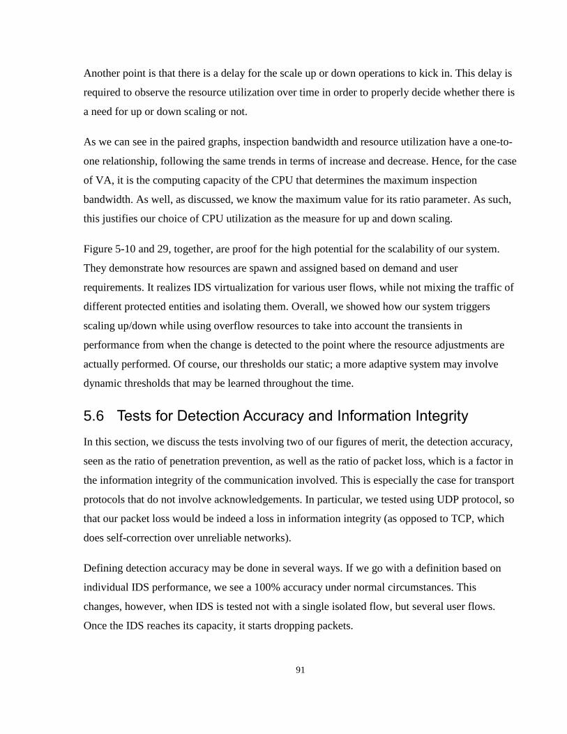
91
Another point is that there is a delay for the scale up or down operations to kick in. This delay is
required to observe the resource utilization over time in order to properly decide whether there is
a need for up or down scaling or not.
As we can see in the paired graphs, inspection bandwidth and resource utilization have a one-to-
one relationship, following the same trends in terms of increase and decrease. Hence, for the case
of VA, it is the computing capacity of the CPU that determines the maximum inspection
bandwidth. As well, as discussed, we know the maximum value for its ratio parameter. As such,
this justifies our choice of CPU utilization as the measure for up and down scaling.
Figure 5-10 and 29, together, are proof for the high potential for the scalability of our system.
They demonstrate how resources are spawn and assigned based on demand and user
requirements. It realizes IDS virtualization for various user flows, while not mixing the traffic of
different protected entities and isolating them. Overall, we showed how our system triggers
scaling up/down while using overflow resources to take into account the transients in
performance from when the change is detected to the point where the resource adjustments are
actually performed. Of course, our thresholds our static; a more adaptive system may involve
dynamic thresholds that may be learned throughout the time.
5.6 Tests for Detection Accuracy and Information Integrity
In this section, we discuss the tests involving two of our figures of merit, the detection accuracy,
seen as the ratio of penetration prevention, as well as the ratio of packet loss, which is a factor in
the information integrity of the communication involved. This is especially the case for transport
protocols that do not involve acknowledgements. In particular, we tested using UDP protocol, so
that our packet loss would be indeed a loss in information integrity (as opposed to TCP, which
does self-correction over unreliable networks).
Defining detection accuracy may be done in several ways. If we go with a definition based on
individual IDS performance, we see a 100% accuracy under normal circumstances. This
changes, however, when IDS is tested not with a single isolated flow, but several user flows.
Once the IDS reaches its capacity, it starts dropping packets.

92
Revisiting our basic functional test, we can say that the possibility of a keyword based attack
penetrating the system (under unencrypted scenario) is zero. However, not all cases of the attack
not penetrating may be due to the IDS blocking it, but it could also be a network issue or IDS
buffer running out. In particular, we tested a scenario when the ratio of attack to benign traffic is
much smaller (less than 0.01 percent) than our functional verification, and still saw a zero
penetration.
However, under attack condition, we expect to initially have zero packet loss, until attack grows
beyond the maximum inspection capacity of the IDS, at which point it start increasing, at the
same rate that the total input traffic of the specific IDS grows. Figure 5-14 shows an example of
our estimate, where the max inspection BW for the individual IDS is 10Mbps, BW growing at a
rate of 2Mbps per second (2 Megabits per second squared).
Figure 5-14 – Expected growth rate of packet loss for a given IDS
For the test, we considered a simple scenario, using UDP packets, generated by Iperf [75]. We
first tested without an attack, and then, with an attack. Similar to before, we used hping3 to
generate DoS traffic, with the period of 1 millisecond (i.e. 1000 packets per second). Figures 36
-5
0
5
10
15
20
25
0 5 10 15 20 25
Pac
ket
Loss
(M
b)
Input Traffic (Mbps)
Expected Packet Loss Rate
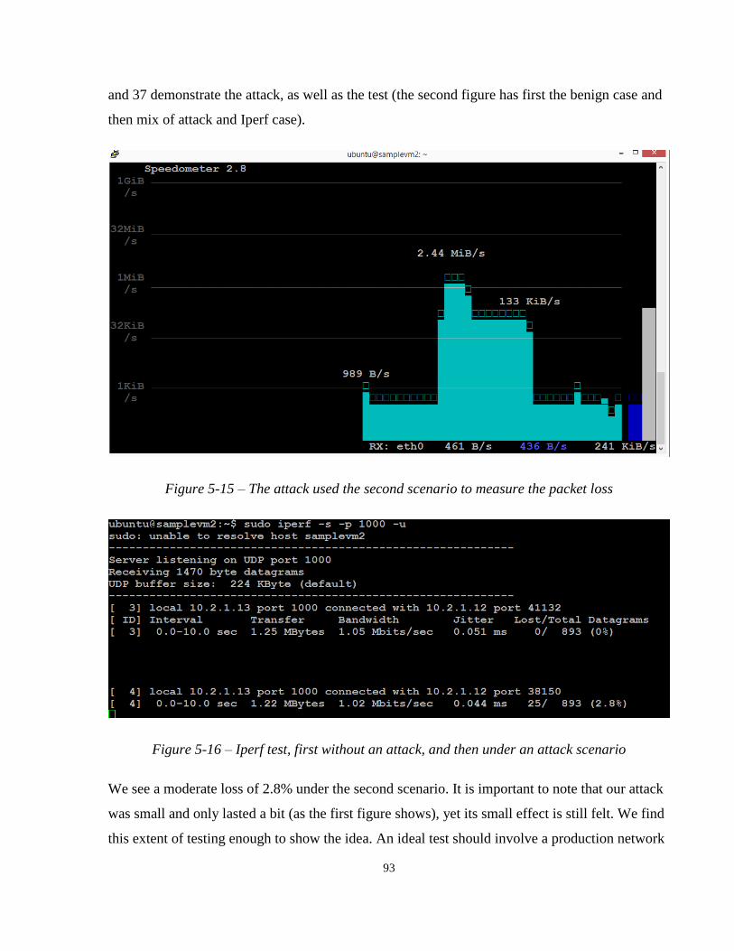
93
and 37 demonstrate the attack, as well as the test (the second figure has first the benign case and
then mix of attack and Iperf case).
Figure 5-15 – The attack used the second scenario to measure the packet loss
Figure 5-16 – Iperf test, first without an attack, and then under an attack scenario
We see a moderate loss of 2.8% under the second scenario. It is important to note that our attack
was small and only lasted a bit (as the first figure shows), yet its small effect is still felt. We find
this extent of testing enough to show the idea. An ideal test should involve a production network
94
traffic, or else, a replay of carefully chosen traffic to simulate a normal network traffic level,
which is beyond the scope of our work.
However, this could indicate the lower bound on our information integrity, as this was done
using the smallest flavor of our VA (vs. a bigger flavor or else the PA). Hence, we expect an
almost 100% integrity below the threshold, and a linearly growing packet loss after threshold
point. We have also demonstrated that we are comfortable with our overall detection accuracy.
95
Chapter 6 Conclusion
In this chapter, we present an overall evaluation of our work and discuss the conclusions we have
obtained. The last two subsections are dedicated to discussing our future work as well as the
contributions we have made.
6.1 Overall Evaluation
Perhaps the best way to evaluate our design to is to look at the extent it has met its desired
requirements. As shown by our functional evaluation, the main desired function, which
signature-based intrusion detection is indeed provided by our system. In terms of mitigation, we
provided the blocking both at individual NIDPSes as well as through our scalable distributed
firewall, which includes the feedback to the switch.
In terms of scalability, we have indeed established a linear relationship through our incremental
analysis in Chapter 5. We saw this in our step-like linear functions for scaling up and down the
number of virtualized resources based on the demand. We showed that our threshold-based
system is very scalable, so long as it’s overflow assigning rate is matched with the input traffic.
Of course, this requires traffic modelling which is outside the scope of our work. Nevertheless,
our claim of scalability is supported by our experiment data, which demonstrate our system
scales based on the demand, leverages overflows, yet has a reasonable overall utilization ratio
(roughly 40% for 2.5 hours of experiment).
We have realized an interoperable solution, and extensible API with relatively little overhead
(e.g. encryption for SSH), which was justified for the added security of our solution. Our
interoperability is demonstrated through the integration of both physical and virtual appliances in
our platform.
While we did not measure the security itself, we showed that our trust distributed approach, the
redundant master controllers, and our proposed self-investigation schemes have increased the
overall reliability of our system.

96
We have demonstrated various levels of security sensitivity, as well as providing the user with
the flexibility of choosing the flavour of security they desire (as well as the trade-offs involved).
We have demonstrated reasonable detection times for various sensitivity levels. Implementing a
user interface and user-centric API, we have demonstrated that our system is user-friendly.
Likewise, we have shown that given the correct / perfect signatures, our system has a near
perfect detection accuracy and information integrity. In particular, packets are not lost unless a
user flow demonstrates rogue behaviours (i.e. going over the reasonably assigned bandwidth
limits). In our case, the capacity of the virtualized resource between 15 to 20 Mbps, which is a
reasonable performance for a cloud-based solution.
Through our relative delay analysis, we showed how our system is capable of assigning the IDS
resource as close as possible to the protected VM (within the cloud network). This helps with
solving the problem we mentioned in our motivation section, which was the lack of applicability
of “periphery” to the cloud networks.
6.2 Future Work
Our future work includes the following:
1- The addition of the Analytics-based detection: The sample implementation could be a
basic clustering algorithm leveraging our IDS assignment API in order to further
investigate traffic detected as anomalous. The clustering algorithm may utilize a cloud
monitoring and measurement system (e.g. looking at the CPU Utilization profile of the
VMs in a given cloud).
2- The implementation of automatic real-time user flow assigner: Our current IDS
assignment scheme is passive, in that it requires the flows to be pre-defined for the IDS
assignment to take place. An alternative approach is to have flows being actively setup in
real-time. This may use a controller that extracts from the packet header the information
defining the user flow (i.e. source and destination IPV4 addresses). There may also be a
static flow setup, giving the direct SSH access to the administrator’s traffic without
having to go through the controller. A major concern for this scheme is the flow setup
time.

97
3- The inclusion of other security resources: NetFPGA, Host-based Intrusion Detection
Systems (HIDSes), legacy firewalls, other PAs and VAs. Our proof-of-concept merely
included only one VA (Snort-based VM) and one PA (Fortigate 111C unit). The more of
those included, the more extensible / interoperable the system is demonstrated to be.
4- Testing with real-time live traffic: This test requires expanding our attack signature set,
which relates to the next suggestion. As well, one shall ensure much stricter user privacy,
in particular, anonymization of the traffic logs.
5- Addition of attack signature / antivirus update scheme. As well, considering to implement
the ESP repository using resilient database than using raw filesystem (current
implementation). The database approach is more scalable, and may include redundancy
to increase the resiliency.
6.3 Contribution
The main focus of our work has been on the network security architecture. Our contribution
includes the following:
- We presented a novel scalable architecture for IDS deployment and management
which takes advantage of the Software Defined Infrastructure’s integrated
management of networking and compute resources.
- By leveraging the SDI’s service chaining and management capabilities, our platform
can locate the desired security resource as close as possible to the entity being
protected. As well, we demonstrated a framework where load balancing is buried in
service chaining / IDS assignment, through logically centralized decision making.
- We introduced the notion of Enhanced Security Groups (ESGs) and Enhanced
Security Profiles in order to communicate and realize the security needs of the user in
the intrusion detection platform. As discussed, this scheme is solid, clear, and novel.
98
- We discussed various aspects of IDS scalability and management / deployment
architectures (hierarchical and flat), and showed that our hierarchical architecture is
quite scalable, distributing the trust, and lacking single points of failure.
- Our approach to IDS deployment was a network service based one. We presented
how our work can be modeled in various paradigms, such as NFV, SDI, and SDN. In
doing so, we presented a pluralistic view in the depiction of our design.
- Our proof-of-concept implementation was quite extensive. We came up with a
flexible implementation where our modules are orchestrated as building blocks to
realize any given user flow topology, yet be load balanced and scale up and down
based on the demand.
At the end, we would like to note that there is no such thing as ultimate security solution for
cloud networking. However, we hope to have made this point clear, that the security schemes
may have to change fundamentally when facing evolving compute and networking paradigms.

References or Bibliography
[1] Center for Strategic and International Studies. (2013, July) The economic impact of
cybercrime and cyber espionage. [Online]. Available:
http://www.mcafee.com/us/resources/reports/rp-economicimpact-cybercrime.pdf
[2] A. Zaharia. (2016, may) 10 alarming cyber security facts that threaten your data. [Online].
Available: https://heimdalsecurity.com/blog/10-surprisingcyber-security-facts-that-may-affect-
your-online-safety
[3] H. P. Strategies. Cybercrime costs more than you think. [Online]. Available:
http://www.hamiltonplacestrategies.com/sites/default/files/newsfiles/HPS%20Cybercrime20.pdf
[4] Statistics Canada. (2016, aug) Canada: Economic and financial data. [Online]. Available:
http://www.statcan.gc.ca/tablestableaux/sum-som/l01/cst01/dsbbcan-eng.htm
[5] PWC. (2016) The global state of information security survey 2016. [Online]. Available:
http://www.pwc.com/gx/en/issues/cybersecurity/information-security-survey.html
[6] Microsoft Inc. (2016) Advanced threat analytics. [Online]. Available:
https://www.microsoft.com/en-us/cloudplatform/advanced-threat-analytics
[7] C. E. Group. (2015) 2015 cyberthreat defense report north america & europe. [Online].
Available:
https://www.bluecoat.com/sites/default/files/documents/files/CyberEdge2015CDRReport:pdf
[8] ISACA. (2015, jan) 2015 global cybersecurity status report. [Online]. Available:
http://www.isaca.org/pages/cybersecurityglobal-status-report.aspx
[9] A. Jumratjaroenvanit and Y. Teng-Amnuay. "Probability of attack based on system
vulnerability life cycle." 2008 International Symposium on Electronic Commerce and Security.
IEEE, 2008.
[10] P. Mell and T. Grance. “The NIST definition of cloud computing,” 2011.

100
[11] Kaspersky Inc. (2015, dec) Security bulletin 2015. [Online]. Available:
https://securelist.com/analysis/kaspersky-securitybulletin/73038/kaspersky-security-bulletin-
2015-overallstatistics-for-2015
[12] Trustwave. (2016) 2016 trustwave global security report. [Online]. Available:
https://www2.trustwave.com/GSR2016.html?utm_source=library\&utm_medium=web\&utm_ca
mpaign=GSR2016
[13] N. Boudriga. (2010). Security of mobile communications. Boca Raton: CRC Press. pp. 32–
33. ISBN 0849379423.
[14] S. Northcutt, L. Zeltzer, S. Winters, K. Fredrick, and R. Ritchey, “Inside Network Perimeter
Security”, New Riders, 2003, p 4
[15] Amazon Inc. (2016). Amazon EC2 Security Groups for Linux Instances. [Online].
Available: http://docs.aws.amazon.com/AWSEC2/latest/UserGuide/using-network-security.html
[16] A. Milenkoski, , M. Vieira, S. Kounev, A. Avritzer, and B. Payne(2015). Evaluating
Computer Intrusion Detection Systems: A Survey of Common Practices. ACM Computing
Surveys (CSUR), 48(1), 12.
[17] T. AbuHmed, A. Mohaisen, and D. Nyang, “A survey on deep packet inspection for
intrusion detection systems,” arXiv preprint arXiv:0803.0037, 2008.
[18] H. Xu (2016, jul). Cloud Native Security Paradigm Shift. [Online]. Available:
https://www.sdxcentral.com/articles/contributed/cloud-native-security-paradigm-shift-2/2016/07
[19] J. H. Saltzer, D. P. Reed, and D. D. Clark, “End-to-end arguments in system design,” ACM
Transactions on Computer Systems (TOCS), vol. 2, no. 4, pp. 277–288, 1984.
[20] L. Armasu (2016, apr). Google’s Zero Trust 'BeyondCorp' Infrastructure Shows Future Of
Network Security. [Online]. Available: http://www.tomsitpro.com/articles/google-beyondcorp-
future-network-security,1-3229.html

101
[21] A. Hussain, J. Heidemann, and C. Papadopoulos, “A framework for classifying denial of
service attacks,” in Proceedings of the 2003 conference on Applications, technologies,
architectures, and protocols for computer communications. ACM, 2003, pp. 99–110.
[22] H. P. Levy (2015, oct). What’s New in Gartner’s Hype Cycle for Emerging Technologies,
2015. [Online]. Available: http://www.gartner.com/smarterwithgartner/whats-new-in-gartners-
hype-cycle-for-emerging-technologies-2015/
[23] A. Raff (2013, dec). From Prevention to Detection: A Paradigm Shift in Enterprise Network
Security. [Online]. Available: http://www.securityweek.com/prevention-detection-paradigm-
shift-enterprise-network-security
[24] U. Frank and S. Strecker, “Open reference models-communitydriven collaboration to
promote development and dissemination of reference models,” Enterprise Modelling and
Information Systems Architectures, vol. 2, no. 2, pp. 32–41, 2015.
[25] S. Monfared, H. Bannazadeh, and A. Leon-Garcia, “Software defined wireless access for a
two-tier cloud system,” in IFIP/IEEE International Symposium on Integrated Network
Management (IM). IEEE, 2015, pp. 566–571.
[26] H. El-Rewini and M. Abd-El-Barr (Apr 2005). Advanced Computer Architecture and
Parallel Processing. John Wiley & Son. p. 63. ISBN 978-0-471-47839-3. Retrieved Oct 2013
[27] G. BDW, “Big data analytics for security intelligence,”
https://downloads.cloudsecurityalliance.org/initiatives/bdwg/Big_Data_Analytics_for_Security_I
ntelligence.pdf, accessed: 2015-12-01.
[28] P. Yasrebi, S. Monfared, H. Bannazadeh, and A. Leon-Garcia, “Security function
virtualization in software defined infrastructure,” in IFIP/IEEE International Symposium on
Integrated Network Management (IM). IEEE, 2015, pp. 778–781.
[29] V. Alfred, “Algorithms for finding patterns in strings,” Algorithms and Complexity, vol. 1,
p. 255, 2014.

102
[30] L. Yang, R. Dantu, T. Anderson, and R. Gopal, “Forwarding and control element separation
(forces) framework,” RFC 3746, April, Tech. Rep., 2004.
[31] N. McKeown, T. Anderson, H. Balakrishnan, G. Parulkar, L. Peterson, J. Rexford, S.
Shenker, and J. Turner, “Openflow: Enabling innovation in campus networks,” SIGCOMM
Comput. Commun. Rev., vol. 38, no. 2, pp. 69–74, Mar. 2008. [Online]. Available:
http://doi.acm.org/10.1145/1355734.1355746
[32] P. Gupta and N. McKeown, “Packet classification on multiple fields,” in ACM SIGCOMM
Computer Communication Review, vol. 29, no. 4. ACM, 1999, pp. 147–160.
[33] C. Cui, H. Deng, D. Telekom, U. Michel, H. Damker, T. Italia, I. Guardini, E. Demaria, R.
Minerva, and A. Manzalini, “Network functions virtualisation.”
[34] G. ETSI, “001,” Network Functions Virtualisation (NFV): Use Cases, vol. 1, 2013.
[35] C. Clark, K. Fraser, S. Hand, J. G. Hansen, E. Jul, C. Limpach, I. Pratt, and A. Warfield,
“Live migration of virtual machines,” in Proceedings of the 2nd conference on Symposium on
Networked Systems Design & Implementation-Volume 2. USENIX Association, 2005, pp. 273–
286.
[36] J.-M. Kang, H. Bannazadeh, H. Rahimi, T. Lin, M. Faraji, and A. Leon-Garcia, “Software-
defined infrastructure and the future central office,” in IEEE International Conference on
Communications (ICC) Workshops, 2013. IEEE, 2013, pp. 225–229.
[37] J.-M. Kang, T. Lin, H. Bannazadeh, and A. Leon-Garcia, “Software-defined infrastructure
and the savi testbed,” in International Conference on Testbeds and Research Infrastructures.
Springer, 2014, pp. 3–13.
[38] M. Ghaznavi, N. Shahriar, R. Ahmed, and R. Boutaba, “Service function chaining
simplified,” arXiv preprint arXiv:1601.00751, 2016.
[39] S. Roschke, F. Cheng, and C. Meinel, “Intrusion detection in the cloud,” in Eighth IEEE
International Conference on Dependable, Autonomic and Secure Computing, 2009. DASC’09.
IEEE, 2009, pp. 729–734.
103
[40] S. N. Dhage and B. Meshram, “Intrusion detection system in cloud computing
environment,” International Journal of Cloud Computing, vol. 1, no. 2-3, pp. 261–282, 2012.
[41] A. M. Lonea, D. E. Popescu, and H. Tianfield, “Detecting ddos attacks in cloud computing
environment,” International Journal of Computers Communications & Control, vol. 8, no. 1, pp.
70–78, 2013.
[42] T. Alharkan and P. Martin, “Idsaas: Intrusion detection system as a service in public
clouds,” in Proceedings of the 2012 12th IEEE/ACM International Symposium on Cluster, Cloud
and Grid Computing (ccgrid 2012). IEEE Computer Society, 2012, pp. 686–687.
[43] S. T. Zargar, H. Takabi, and J. B. Joshi, “Dcdidp: A distributed, collaborative, and data-
driven intrusion detection and prevention framework for cloud computing environments,” in 7th
International Conference on Collaborative Computing: Networking, Applications and
Worksharing (CollaborateCom), 2011. IEEE, 2011, pp. 332–341.
[44] C.-C. Lo, C.-C. Huang, and J. Ku, “A cooperative intrusion detection system framework for
cloud computing networks,” in 39th International Conference on Parallel Processing Workshops.
IEEE, 2010, pp. 280–284.
[45] C. Mazzariello, R. Bifulco, and R. Canonico, “Integrating a network ids into an open source
cloud computing environment,” in Sixth International Conference on Information Assurance and
Security (IAS). IEEE, 2010, pp. 265–270.
[46] A. Bakshi and Y. B. Dujodwala, “Securing cloud from ddos attacks using intrusion
detection system in virtual machine,” in Second International Conference on Communication
Software and Networks, 2010. ICCSN’10. IEEE, 2010, pp. 260– 264.
[47] H. Hamad and M. Al-Hoby, “Managing intrusion detection as a service in cloud networks,”
International Journal of Computer Applications, vol. 41, no. 1, 2012.
[48] IETF Network Working Group (2007, mar). The Intrusion Detection Message Exchange
Format. [Online]. Available: https://www.ietf.org/rfc/rfc4765.txt

104
[49] J. Hoagland, S. Staniford et al., “Viewing ids alerts: Lessons from snortsnarf,” in DARPA
Information Survivability Conference & Exposition II, 2001. DISCEX’01. Proceedings, vol.
1. IEEE, 2001, pp. 374–386.
[50] A. Hutchison and M. Welz, “Ids/a: An interface between intrusion detection system and
application,” in Recent Advances in Intrusion Detection, Third International Workshop,
RAID2000, Toulouse, France,
http://www.Raidsymposium.org/raid2000/Materials/Abstracts/21/21. pdf. Citeseer, 2000, p. 13.
[51] Designing Engineers: An Introductory Textbook (S. McCahan, P. Anderson, M. Kortschot,
P. Weiss, and K.Woodhouse )
[52] Provos, Niels. "A Virtual Honeypot Framework." In USENIX Security Symposium, vol.
173, pp. 1-14. 2004.
[53] Prevelakis, Vassilis, and Diomidis Spinellis. "Sandboxing Applications." In USENIX
Annual Technical Conference, FREENIX Track, pp. 119-126. 2001.
[54] C. Cui, H. Deng, U. Michel, and H. Damker. "Network Functions Virtualization. An
Introduction, Benefits, Enablers, Challenges & Call for Action". [Online] Available:
http://course.ipv6.club.tw/SDN/nfv_white_paper.pdf
[55] R. Jain, and P. Subharthi. "Network virtualization and software defined networking for
cloud computing: a survey." IEEE Communications Magazine 51, no. 11 (2013): 24-31.
[56] "Network Functions Virtualisation (NFV); Terminology for Main Concepts in NFV" (PDF).
Retrieved July 2016.
http://www.etsi.org/deliver/etsi_gs/NFV/001_099/003/01.02.01_60/gs_nfv003v010201p.pdf
[57] M. Roesch et al., “Snort: Lightweight intrusion detection for networks.” in LISA, vol. 99,
no. 1, 1999, pp. 229–238.
[58] B. Pfaff, J. Pettit, T. Koponen, E. Jackson, A. Zhou, J. Rajahalme, J. Gross, A. Wang, J.
Stringer, P. Shelar et al., “The design and implementation of open vswitch,” in 12th USENIX
symposium on networked systems design and implementation (NSDI 15), 2015, pp. 117–130.

105
[59] Fortinet Inc. Fortigate 111C Quick Start Guide. [Online]. Available:
http://docs.fortinet.com/uploaded/files/845/FortiGate-111C_QuickStart_Guide_01-30007-0469-
20090415.pdf
[60] SANS Institute (2002). Using Snort For a Distributed Intrusion Detection System. [Online].
Available: https://www.sans.org/reading-room/whitepapers/detection/snort-distributed-intrusion-
detection-system-352
[61] Gartner Inc. (2016) Gartner fortinet firewall market share 2016. [Online]. Available:
http://www.slideshare.net/zztop_2764/gartner-fortinet-firewall-market-share-2016
[62] F. Belqasmi, R. Glitho, and C. Fu, “Restful web services for service provisioning in next-
generation networks: a survey,” IEEE Communications Magazine, vol. 49, no. 12, pp. 66–73,
2011.
[63] D. A. Menascé, "Security performance." IEEE Internet Computing 7, no. 3 (2003): 84-87.
[64] M. Faraji, “Identity and access management in multi-tier cloud infrastructure,” Ph.D.
dissertation, Citeseer, 2013.
[65] Docker Inc. (2016) What is Docker? [Online]. Available: https://www.docker.com/what-
docker
[66] The OpenFlow Team (2011, feb). OpenFlow Switch Specification Version 1.1.0. [Online].
Available: http://archive.openflow.org/documents/openflow-spec-v1.1.0.pdf
[67] OpenStack Foundation. Heat. [Online]. Available: https://wiki.openstack.org/wiki/Heat
[68] “Express” [Online]. Available: https://www.npmjs.com/package/express
[69] “Bootstrap” [Online]. Available: http://getbootstrap.com, accessed: 2015-12-01.
[70] “TCPDUMP Manual” [Online]. Available: http://www.tcpdump.org/tcpdump_man.html
[71] “hping security tool – man page” [Online]. Available: http://www.hping.org/manpage.html
[72] “Speedometer” [Online]. Available: https://excess.org/speedometer, accessed: 2015-12-01.

106
[73] D. Katabi, M. Handley, and C. Rohrs, “Congestion control for high bandwidth-delay
product networks,” ACM SIGCOMM computer communication review, vol. 32, no. 4, pp. 89–
102, 2002.
[74] “Netcat user manual,” [Online]. Available: http://www.r3v0.net/docs/Delta/man/nc.html,
accessed: 2015-12-01.
[75] “IPFERF” [Online]. Available: https://iperf.fr