colibri evaluation board datasheet - főmenü - vilivili.pmmf.hu/~zamek/embedded/colibri evalboard...
TRANSCRIPT
Toradex AG l Altsagenstrasse 5 l 6048 Horw l Switzerland l +41 41 340 80 85 l www.toradex.com l [email protected]
high performance low power computing
Colibri Evaluation Board Datasheet
Revision History
Date Doc. Rev. Colibri Evalboard Version
Changes
13-05-05 Rev. 1.0 V1.00b / V1.10 Initial release
18-05-05 Rev. 1.1 V1.00b / V1.10 Added dimension-drawing Added power supply chapter
11-04-06 Rev. 2.0 V2.1b Changed references, New pinout for the JTAG connector, New connectors for CIF, generic display, spare and generic touch screen, Reset.
07-03-07 Rev.2.1 V2.1b CAN connector type corrected
Colibri Evalboard Datasheet
Toradex AG l Altsagenstrasse 5 l 6048 Horw l Switzerland l +41 41 340 80 85 l www.toradex.com l [email protected] l 2/26
Content 1. Introduction 3
1.1. Features 3 1.2. Reference Documents 4
2. Installation 5 3. Evaluation Board Physical Drawings 5
3.1. Connector Locations 5 3.2. Mechanical Drawing 7
4. Evaluation Board Connectors 8 4.1. Colibri Module 8 4.2. Display 8 4.3. PS/2 11 4.4. LEDs / Switches 11 4.5. Audio 12 4.6. USB 12 4.7. RS232 13 4.8. Ethernet 13 4.9. CIF 14 4.10. CAN 14 4.11. Card slots 15 4.12. GPIO Usage 16 4.13. User Extension 20 4.14. Analog IO 21 4.15. Reset 22 4.16. JTAG 22
5. Default signal mapping 24 5.1. GPIO 1 mapping 24 5.2. GPIO 2 mapping 25
Colibri Evalboard Datasheet
Toradex AG l Altsagenstrasse 5 l 6048 Horw l Switzerland l +41 41 340 80 85 l www.toradex.com l [email protected] l 3/26
1. Introduction The Colibri Evaluation Board is designed to be a flexible development environment to explore the functionality and performance of the Intel XScale® based Colibri modules.
Besides the user interfaces it provides numerous communication channels as well as an configurable jumper area to hook up the Colibri GPIOs to the desired function. To facilitate interfacing to custom hardware the Colibri EvalBoard provides the buffered CPU bus on a separate connector.
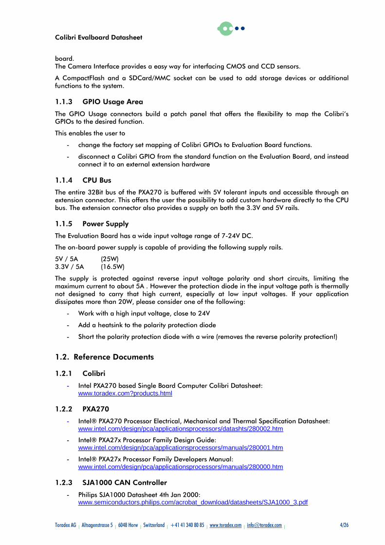
1.1. Features
10 Switches8 LED
1x USB Host1x USB Host/Device
2 x PS/2 10/100MBit Ethernet
1 x VGA1 x TFT
1 x SD-Card1 x CF
CAN
Audio I/O 2xRS232IrDA
CPU Bus (2.54mm Connector)
GPIOs (2.54mm Jumper Field)
Exte
nsio
ns
Use
r In
terf
ace
Expa
nsi
on
Car
ds
Com
mun
icatio
n
Fig. 1: Evaluation Board Block Diagram
1.1.1 User Interface
The Colibri Evaluation Board provides an analog VGA connector to attach a standard computer monitor.
LCDs can also be connected through the digital LCD port. Since there is no standard connector for LCD panels, users usually need to build their own connector interface which attaches to the generic display header provided by the Evaluation Board. But there is also a dedicated connector for the LG.Philips LB064V02-A1 TFT (6.4“, 640x480, 6 Bit) integrated on the board.
Keyboard and mouse can be attached through PS/2 connectors or the USB port.
Furthermore the Colibri EvalBoard provides switches, buttons and LEDs for simple user interaction.
Audio input and output is available on standard jacks.
1.1.2 Communication
The most commonly used communication functions are fully implemented on the Evaluation Board: 10/100Mb Ethernet, USB Host and Client, two RS232 channels, one IrDA serial port and a CAN interface. For all these communication channels the industry standard connectors are provided on-
Colibri Evalboard Datasheet
Toradex AG l Altsagenstrasse 5 l 6048 Horw l Switzerland l +41 41 340 80 85 l www.toradex.com l [email protected] l 4/26
board. The Camera Interface provides a easy way for interfacing CMOS and CCD sensors.
A CompactFlash and a SDCard/MMC socket can be used to add storage devices or additional functions to the system.
1.1.3 GPIO Usage Area
The GPIO Usage connectors build a patch panel that offers the flexibility to map the Colibri’s GPIOs to the desired function.
This enables the user to
- change the factory set mapping of Colibri GPIOs to Evaluation Board functions.
- disconnect a Colibri GPIO from the standard function on the Evaluation Board, and instead connect it to an external extension hardware
1.1.4 CPU Bus
The entire 32Bit bus of the PXA270 is buffered with 5V tolerant inputs and accessible through an extension connector. This offers the user the possibility to add custom hardware directly to the CPU bus. The extension connector also provides a supply on both the 3.3V and 5V rails.
1.1.5 Power Supply
The Evaluation Board has a wide input voltage range of 7-24V DC.
The on-board power supply is capable of providing the following supply rails.
5V / 5A (25W) 3.3V / 5A (16.5W)
The supply is protected against reverse input voltage polarity and short circuits, limiting the maximum current to about 5A . However the protection diode in the input voltage path is thermally not designed to carry that high current, especially at low input voltages. If your application dissipates more than 20W, please consider one of the following:
- Work with a high input voltage, close to 24V
- Add a heatsink to the polarity protection diode
- Short the polarity protection diode with a wire (removes the reverse polarity protection!)
1.2. Reference Documents
1.2.1 Colibri
- Intel PXA270 based Single Board Computer Colibri Datasheet: www.toradex.com?products.html
1.2.2 PXA270
- Intel® PXA270 Processor Electrical, Mechanical and Thermal Specification Datasheet: www.intel.com/design/pca/applicationsprocessors/datashts/280002.htm
- Intel® PXA27x Processor Family Design Guide: www.intel.com/design/pca/applicationsprocessors/manuals/280001.htm
- Intel® PXA27x Processor Family Developers Manual: www.intel.com/design/pca/applicationsprocessors/manuals/280000.htm
1.2.3 SJA1000 CAN Controller
- Philips SJA1000 Datasheet 4th Jan 2000: www.semiconductors.philips.com/acrobat_download/datasheets/SJA1000_3.pdf

Colibri Evalboard Datasheet
Toradex AG l Altsagenstrasse 5 l 6048 Horw l Switzerland l +41 41 340 80 85 l www.toradex.com l [email protected] l 5/26
- Philips SJA1000 Application Note AN97076: www.semiconductors.philips.com/acrobat_download/applicationnotes/AN97076.pdf
2. Installation Follow these steps for a jump start with the EvalBoard:
1. If not already done, insert a Colibri Module in the SODIMM socket M2 on the EvalBoard
2. Plug in a VGA monitor on the corresponding connector X24, a keyboard and a mouse on the PS/2 interfaces X27
3. Connect an external power supply to the board by the X1 connector (7-24V, 3W min, depending on your peripherals)
4. Turn on the external power supply
5. Push down the power button S1 on the EvalBoard
Now the preinstalled operating system will boot.
For a detailed documentation of the software as well as for the newest bootloader and software images please refer to the Colibri Web site: www.toradex.com?products.html
3. Evaluation Board Physical Drawings
3.1. Connector Locations
Fig. 2: Evaluation Board Layout: Top View
Colibri Evalboard Datasheet
Toradex AG l Altsagenstrasse 5 l 6048 Horw l Switzerland l +41 41 340 80 85 l www.toradex.com l [email protected] l 6/26
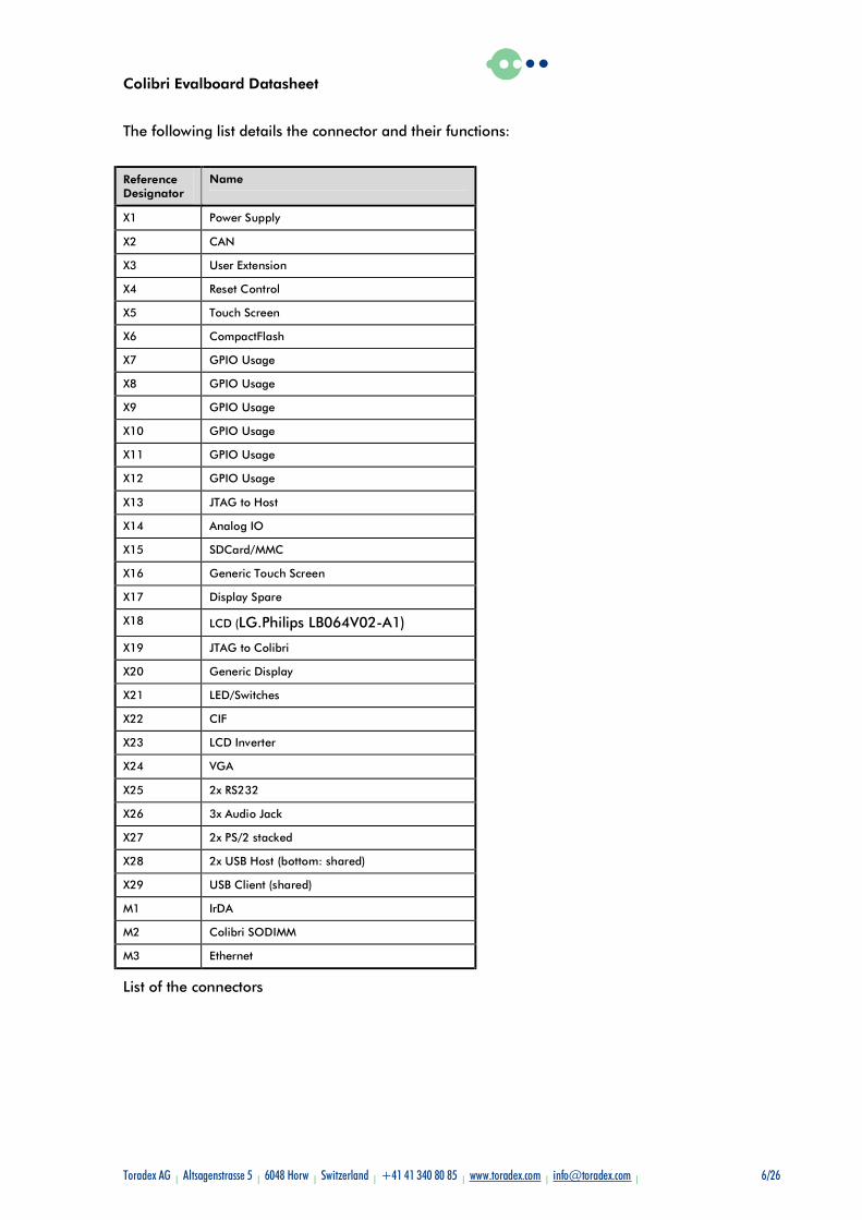
The following list details the connector and their functions:
Reference Designator
Name
X1 Power Supply
X2 CAN
X3 User Extension
X4 Reset Control
X5 Touch Screen
X6 CompactFlash
X7 GPIO Usage
X8 GPIO Usage
X9 GPIO Usage
X10 GPIO Usage
X11 GPIO Usage
X12 GPIO Usage
X13 JTAG to Host
X14 Analog IO
X15 SDCard/MMC
X16 Generic Touch Screen
X17 Display Spare
X18 LCD (LG.Philips LB064V02-A1)
X19 JTAG to Colibri
X20 Generic Display
X21 LED/Switches
X22 CIF
X23 LCD Inverter
X24 VGA
X25 2x RS232
X26 3x Audio Jack
X27 2x PS/2 stacked
X28 2x USB Host (bottom: shared)
X29 USB Client (shared)
M1 IrDA
M2 Colibri SODIMM
M3 Ethernet
List of the connectors
Colibri Evalboard Datasheet
Toradex AG l Altsagenstrasse 5 l 6048 Horw l Switzerland l +41 41 340 80 85 l www.toradex.com l [email protected] l 7/26
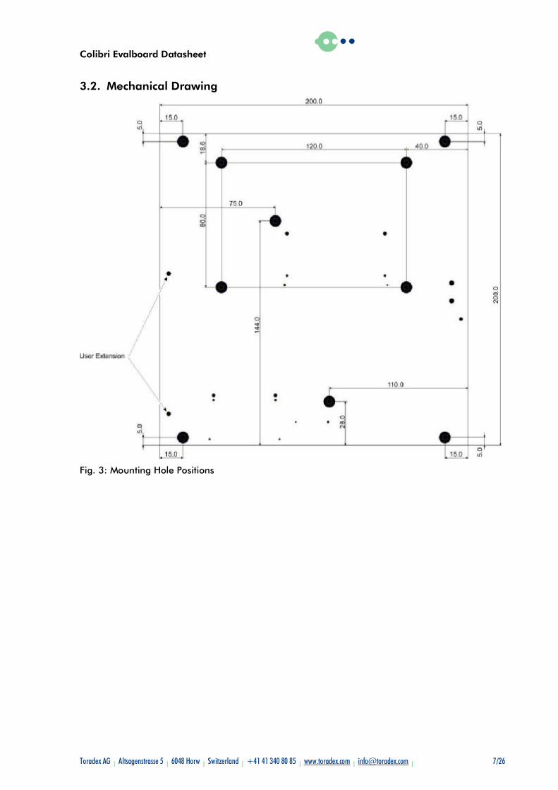
3.2. Mechanical Drawing
Fig. 3: Mounting Hole Positions
Colibri Evalboard Datasheet
Toradex AG l Altsagenstrasse 5 l 6048 Horw l Switzerland l +41 41 340 80 85 l www.toradex.com l [email protected] l 8/26
4. Evaluation Board Connectors
4.1. Colibri Module
4.1.1 Colibri Module (M2)
Type: SODIMM 200 Socket
Manufacturer tyco electronics-1473005-1
For the pinout of the Colibri module please refer to the Colibri Datasheet for which a link is listed in chapter 1.2.1
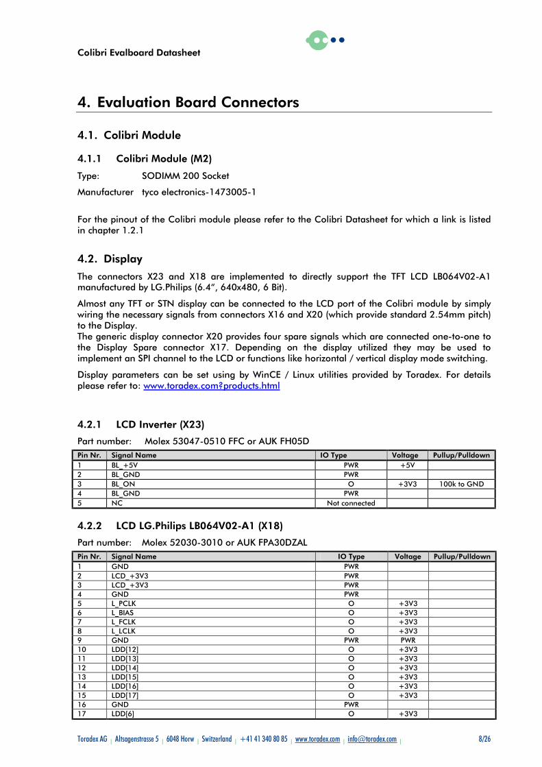
4.2. Display
The connectors X23 and X18 are implemented to directly support the TFT LCD LB064V02-A1 manufactured by LG.Philips (6.4“, 640x480, 6 Bit).
Almost any TFT or STN display can be connected to the LCD port of the Colibri module by simply wiring the necessary signals from connectors X16 and X20 (which provide standard 2.54mm pitch) to the Display. The generic display connector X20 provides four spare signals which are connected one-to-one to the Display Spare connector X17. Depending on the display utilized they may be used to implement an SPI channel to the LCD or functions like horizontal / vertical display mode switching.
Display parameters can be set using by WinCE / Linux utilities provided by Toradex. For details please refer to: www.toradex.com?products.html
4.2.1 LCD Inverter (X23)
Part number: Molex 53047-0510 FFC or AUK FH05D Pin Nr. Signal Name IO Type Voltage Pullup/Pulldown 1 BL_+5V PWR +5V 2 BL_GND PWR 3 BL_ON O +3V3 100k to GND 4 BL_GND PWR 5 NC Not connected
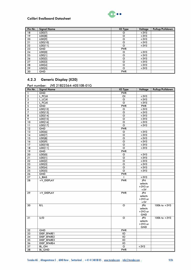
4.2.2 LCD LG.Philips LB064V02-A1 (X18)
Part number: Molex 52030-3010 or AUK FPA30DZAL Pin Nr. Signal Name IO Type Voltage Pullup/Pulldown 1 GND PWR 2 LCD_+3V3 PWR 3 LCD_+3V3 PWR 4 GND PWR 5 L_PCLK O +3V3 6 L_BIAS O +3V3 7 L_FCLK O +3V3 8 L_LCLK O +3V3 9 GND PWR PWR 10 LDD[12] O +3V3 11 LDD[13] O +3V3 12 LDD[14] O +3V3 13 LDD[15] O +3V3 14 LDD[16] O +3V3 15 LDD[17] O +3V3 16 GND PWR 17 LDD[6] O +3V3
Colibri Evalboard Datasheet
Toradex AG l Altsagenstrasse 5 l 6048 Horw l Switzerland l +41 41 340 80 85 l www.toradex.com l [email protected] l 9/26
Pin Nr. Signal Name IO Type Voltage Pullup/Pulldown 18 LDD[7] O +3V3 19 LDD[8] O +3V3 20 LDD[9] O +3V3 21 LDD[10] O +3V3 22 LDD[11] O +3V3 23 GND PWR 24 LDD[0] O +3V3 25 LDD[1] O +3V3 26 LDD[2] O +3V3 27 LDD[3] O +3V3 28 LDD[4] O +3V3 29 LDD[5] O +3V3 30 GND PWR
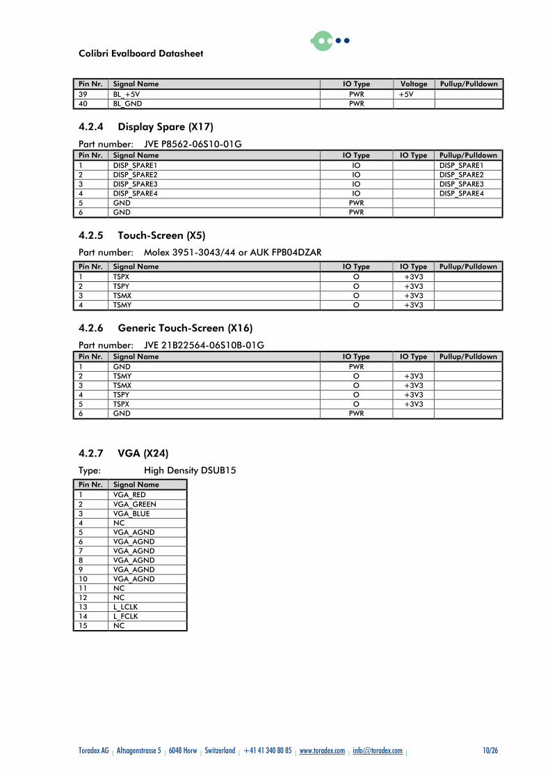
4.2.3 Generic Display (X20)
Part number: JVE 21B22564-40S10B-01G Pin Nr. Signal Name IO Type Voltage Pullup/Pulldown 1 GND PWR 2 L_PCLK OI +3V3 3 L_LCLK O +3V3 4 L_FCLK O +3V3 5 GND PWR PWR 6 LDD[12] O +3V3 7 LDD[13] O +3V3 8 LDD[14] O +3V3 9 LDD[15] O +3V3 10 LDD[16] O +3V3 11 LDD[17] O +3V3 12 GND PWR 13 LDD[6] O +3V3 14 LDD[7] O +3V3 15 LDD[8] O +3V3 16 LDD[9] O +3V3 17 LDD[10] O +3V3 18 LDD[11] O +3V3 19 GND PWR 20 LDD[0] O +3V3 21 LDD[1] O +3V3 22 LDD[2] O +3V3 23 LDD[3] O +3V3 24 LDD[4] O +3V3 25 LDD[5] O +3V3 26 GND PWR 27 L_BIAS I +3V3 28 +V_DISPLAY PWR JP4
selects +3V3 or
+5V
29 +V_DISPLAY PWR JP4 selects
+3V3 or +5V
30 R/L O JP6 selects
+3V3 or GND
100k to +3V3
31 U/D O JP5 selects
+3V3 or GND
100k to +3V3
32 GND PWR 33 DISP_SPARE1 IO 34 DISP_SPARE2 IO 35 DISP_SPARE3 IO 36 DISP_SPARE4 IO 37 BL_ON O +3V3 38 BL_GND PWR
Colibri Evalboard Datasheet
Toradex AG l Altsagenstrasse 5 l 6048 Horw l Switzerland l +41 41 340 80 85 l www.toradex.com l [email protected] l 10/26
Pin Nr. Signal Name IO Type Voltage Pullup/Pulldown 39 BL_+5V PWR +5V 40 BL_GND PWR
4.2.4 Display Spare (X17)
Part number: JVE P8562-06S10-01G Pin Nr. Signal Name IO Type IO Type Pullup/Pulldown 1 DISP_SPARE1 IO DISP_SPARE1 2 DISP_SPARE2 IO DISP_SPARE2 3 DISP_SPARE3 IO DISP_SPARE3 4 DISP_SPARE4 IO DISP_SPARE4 5 GND PWR 6 GND PWR
4.2.5 Touch-Screen (X5)
Part number: Molex 3951-3043/44 or AUK FPB04DZAR Pin Nr. Signal Name IO Type IO Type Pullup/Pulldown 1 TSPX O +3V3 2 TSPY O +3V3 3 TSMX O +3V3 4 TSMY O +3V3
4.2.6 Generic Touch-Screen (X16)
Part number: JVE 21B22564-06S10B-01G Pin Nr. Signal Name IO Type IO Type Pullup/Pulldown 1 GND PWR 2 TSMY O +3V3 3 TSMX O +3V3 4 TSPY O +3V3 5 TSPX O +3V3 6 GND PWR
4.2.7 VGA (X24)
Type: High Density DSUB15 Pin Nr. Signal Name 1 VGA_RED 2 VGA_GREEN 3 VGA_BLUE 4 NC 5 VGA_AGND 6 VGA_AGND 7 VGA_AGND 8 VGA_AGND 9 VGA_AGND 10 VGA_AGND 11 NC 12 NC 13 L_LCLK 14 L_FCLK 15 NC
Colibri Evalboard Datasheet
Toradex AG l Altsagenstrasse 5 l 6048 Horw l Switzerland l +41 41 340 80 85 l www.toradex.com l [email protected] l 11/26
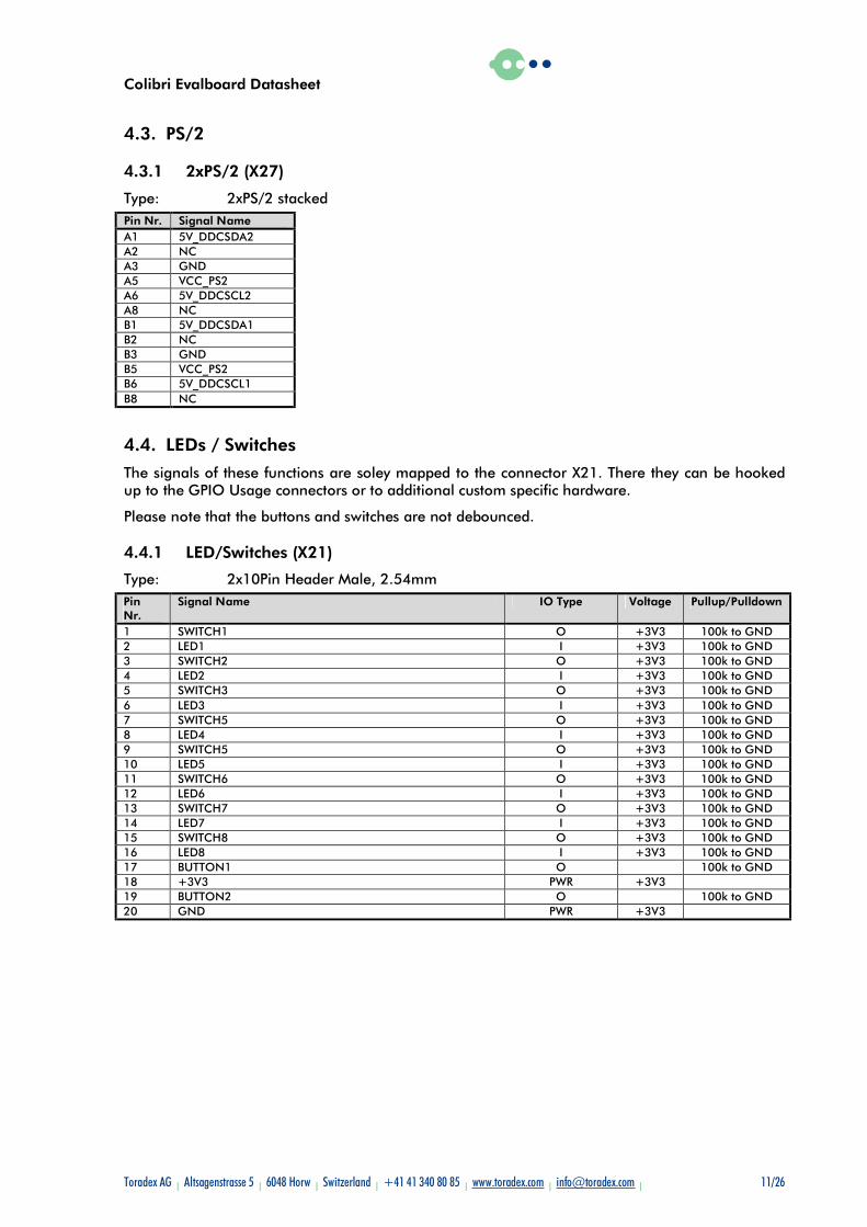
4.3. PS/2
4.3.1 2xPS/2 (X27)
Type: 2xPS/2 stacked Pin Nr. Signal Name A1 5V_DDCSDA2 A2 NC A3 GND A5 VCC_PS2 A6 5V_DDCSCL2 A8 NC B1 5V_DDCSDA1 B2 NC B3 GND B5 VCC_PS2 B6 5V_DDCSCL1 B8 NC
4.4. LEDs / Switches
The signals of these functions are soley mapped to the connector X21. There they can be hooked up to the GPIO Usage connectors or to additional custom specific hardware.
Please note that the buttons and switches are not debounced.
4.4.1 LED/Switches (X21)
Type: 2x10Pin Header Male, 2.54mm Pin Nr.
Signal Name IO Type Voltage Pullup/Pulldown
1 SWITCH1 O +3V3 100k to GND 2 LED1 I +3V3 100k to GND 3 SWITCH2 O +3V3 100k to GND 4 LED2 I +3V3 100k to GND 5 SWITCH3 O +3V3 100k to GND 6 LED3 I +3V3 100k to GND 7 SWITCH5 O +3V3 100k to GND 8 LED4 I +3V3 100k to GND 9 SWITCH5 O +3V3 100k to GND 10 LED5 I +3V3 100k to GND 11 SWITCH6 O +3V3 100k to GND 12 LED6 I +3V3 100k to GND 13 SWITCH7 O +3V3 100k to GND 14 LED7 I +3V3 100k to GND 15 SWITCH8 O +3V3 100k to GND 16 LED8 I +3V3 100k to GND 17 BUTTON1 O 100k to GND 18 +3V3 PWR +3V3 19 BUTTON2 O 100k to GND 20 GND PWR +3V3
Colibri Evalboard Datasheet
Toradex AG l Altsagenstrasse 5 l 6048 Horw l Switzerland l +41 41 340 80 85 l www.toradex.com l [email protected] l 12/26
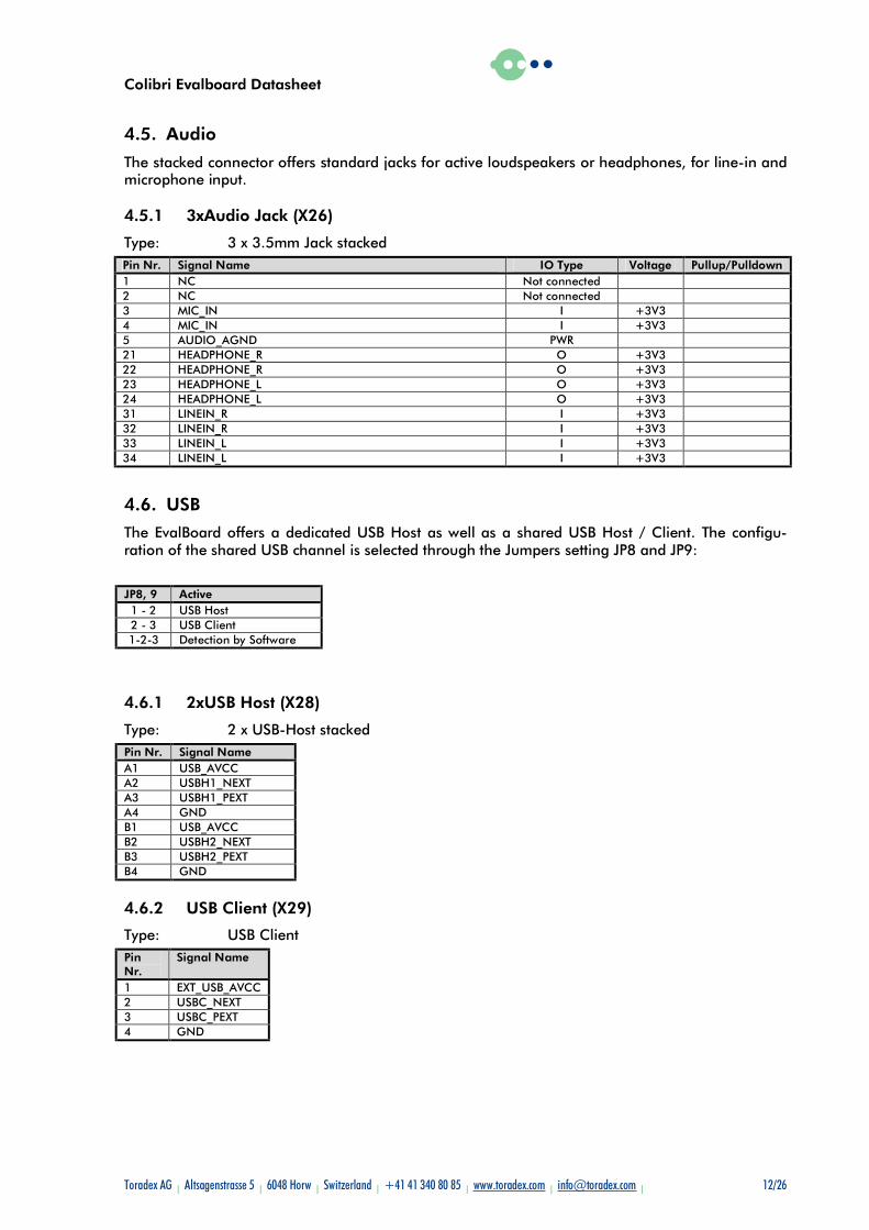
4.5. Audio
The stacked connector offers standard jacks for active loudspeakers or headphones, for line-in and microphone input.
4.5.1 3xAudio Jack (X26)
Type: 3 x 3.5mm Jack stacked Pin Nr. Signal Name IO Type Voltage Pullup/Pulldown 1 NC Not connected 2 NC Not connected 3 MIC_IN I +3V3 4 MIC_IN I +3V3 5 AUDIO_AGND PWR 21 HEADPHONE_R O +3V3 22 HEADPHONE_R O +3V3 23 HEADPHONE_L O +3V3 24 HEADPHONE_L O +3V3 31 LINEIN_R I +3V3 32 LINEIN_R I +3V3 33 LINEIN_L I +3V3 34 LINEIN_L I +3V3
4.6. USB
The EvalBoard offers a dedicated USB Host as well as a shared USB Host / Client. The configu-ration of the shared USB channel is selected through the Jumpers setting JP8 and JP9:
JP8, 9 Active 1 - 2 USB Host 2 - 3 USB Client 1-2-3 Detection by Software
4.6.1 2xUSB Host (X28)
Type: 2 x USB-Host stacked Pin Nr. Signal Name A1 USB_AVCC A2 USBH1_NEXT A3 USBH1_PEXT A4 GND B1 USB_AVCC B2 USBH2_NEXT B3 USBH2_PEXT B4 GND
4.6.2 USB Client (X29)
Type: USB Client Pin Nr.
Signal Name
1 EXT_USB_AVCC 2 USBC_NEXT 3 USBC_PEXT 4 GND
Colibri Evalboard Datasheet
Toradex AG l Altsagenstrasse 5 l 6048 Horw l Switzerland l +41 41 340 80 85 l www.toradex.com l [email protected] l 13/26
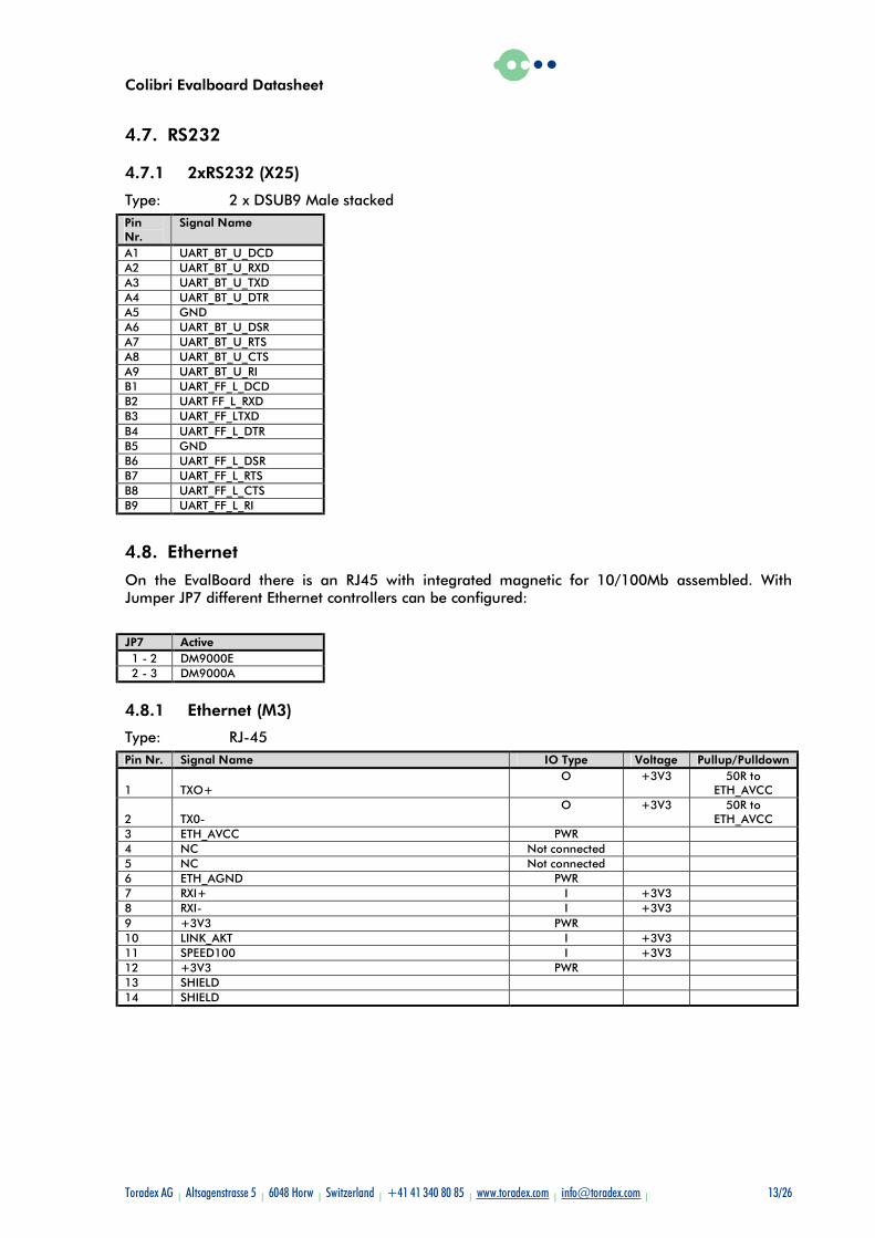
4.7. RS232
4.7.1 2xRS232 (X25)
Type: 2 x DSUB9 Male stacked Pin Nr.
Signal Name
A1 UART_BT_U_DCD A2 UART_BT_U_RXD A3 UART_BT_U_TXD A4 UART_BT_U_DTR A5 GND A6 UART_BT_U_DSR A7 UART_BT_U_RTS A8 UART_BT_U_CTS A9 UART_BT_U_RI B1 UART_FF_L_DCD B2 UART FF_L_RXD B3 UART_FF_LTXD B4 UART_FF_L_DTR B5 GND B6 UART_FF_L_DSR B7 UART_FF_L_RTS B8 UART_FF_L_CTS B9 UART_FF_L_RI
4.8. Ethernet
On the EvalBoard there is an RJ45 with integrated magnetic for 10/100Mb assembled. With Jumper JP7 different Ethernet controllers can be configured:
JP7 Active 1 - 2 DM9000E 2 - 3 DM9000A
4.8.1 Ethernet (M3)
Type: RJ-45 Pin Nr. Signal Name IO Type Voltage Pullup/Pulldown
1 TXO+ O +3V3 50R to
ETH_AVCC
2 TX0- O +3V3 50R to
ETH_AVCC 3 ETH_AVCC PWR 4 NC Not connected 5 NC Not connected 6 ETH_AGND PWR 7 RXI+ I +3V3 8 RXI- I +3V3 9 +3V3 PWR 10 LINK_AKT I +3V3 11 SPEED100 I +3V3 12 +3V3 PWR 13 SHIELD 14 SHIELD
Colibri Evalboard Datasheet
Toradex AG l Altsagenstrasse 5 l 6048 Horw l Switzerland l +41 41 340 80 85 l www.toradex.com l [email protected] l 14/26
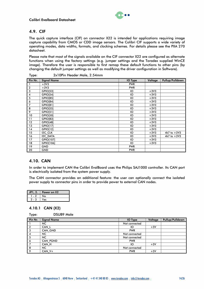
4.9. CIF
The quick capture interface (CIF) on connector X22 is intended for applications requiring image capture capability from CMOS or CDD image sensors. The Colibri CIF supports a wide variety of operating modes, data widths, formats, and clocking schemes. For details please see the PXA 270 datasheet.
Please note that most of the signals available on the CIF connector X22 are configured as alternate functions when using the factory settings (e.g. jumper settings and the Toradex supplied WinCE image). Therefore the user is responsible to first remap these default functions to other pins (by changing the default jumper settings as well as modifying the driver configuration in Software).
Type: 2x10Pin Header Male, 2.54mm Pin Nr. Signal Name IO Type Voltage Pullup/Pulldown 1 +3V3 PWR 2 +3V3 PWR 3 GPIO[53] IO +3V3 4 GPIO[54] IO +3V3 5 GPIO[85] IO +3V3 6 GPIO[84] IO +3V3 7 GPIO[81] IO +3V3 8 GPIO[55] IO +3V3 9 GPIO[51] IO +3V3 10 GPIO[50] IO +3V3 11 GPIO[83] IO +3V3 12 GPIO[48] IO +3V3 13 GPIO[17] IO +3V3 14 GPIO[12] IO +3V3 15 I2C_CLK IO +3V3 4k7 to +3V3 16 I2C_DATA IO +3V3 4k7 to +3V3 17 GPIO[107] IO +3V3 18 GPIO[106] IO +3V3 19 GND PWR 20 GND PWR
4.10. CAN
In order to implement CAN the Colibri EvalBoard uses the Philips SAJ1000 controller. Its CAN port is electrically isolated from the system power supply.
The CAN connector provides an additional feature: the user can optionally connect the isolated power supply to connector pins in order to provide power to external CAN nodes.
JP1, 2. Power on X2 1 - 2 No 2 - 3 Yes
4.10.1 CAN (X2)
Type: DSUB9 Male Pin Nr. Signal Name IO Type Voltage Pullup/Pulldown 1 NC Not connected 2 CAN_L IO +5V 3 CAN_GND PWR 4 NC Not connected 5 NC Not connected 6 CAN_PGND PWR 7 CAN_H IO +5V 8 NC Not connected 9 CAN_V+ PWR +5V
Colibri Evalboard Datasheet
Toradex AG l Altsagenstrasse 5 l 6048 Horw l Switzerland l +41 41 340 80 85 l www.toradex.com l [email protected] l 15/26
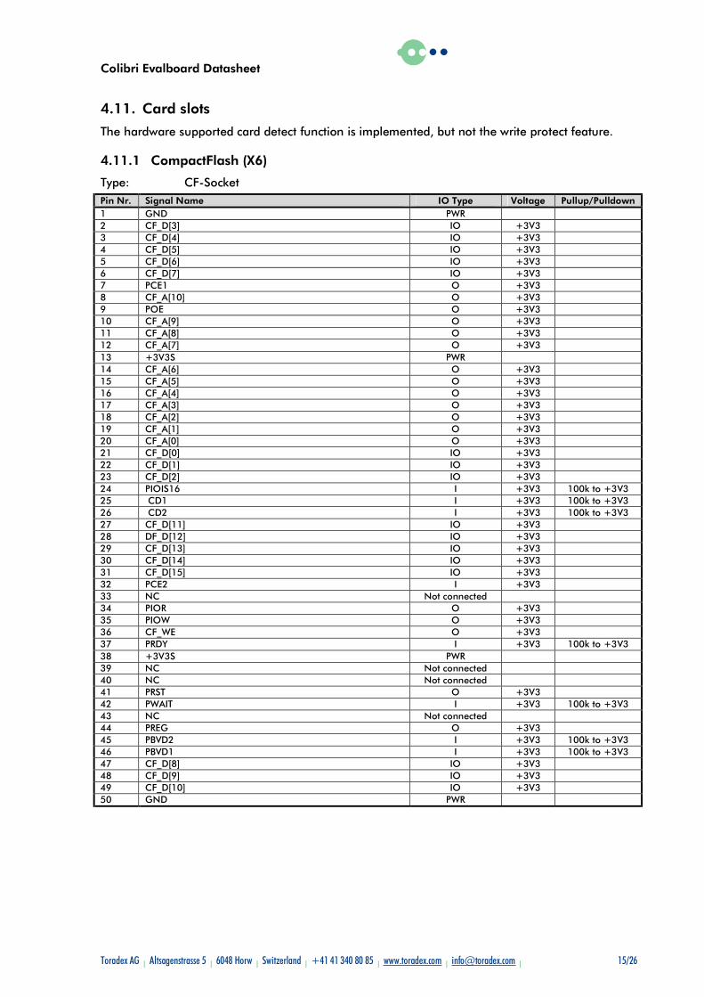
4.11. Card slots
The hardware supported card detect function is implemented, but not the write protect feature.
4.11.1 CompactFlash (X6)
Type: CF-Socket Pin Nr. Signal Name IO Type Voltage Pullup/Pulldown 1 GND PWR 2 CF_D[3] IO +3V3 3 CF_D[4] IO +3V3 4 CF_D[5] IO +3V3 5 CF_D[6] IO +3V3 6 CF_D[7] IO +3V3 7 PCE1 O +3V3 8 CF_A[10] O +3V3 9 POE O +3V3 10 CF_A[9] O +3V3 11 CF_A[8] O +3V3 12 CF_A[7] O +3V3 13 +3V3S PWR 14 CF_A[6] O +3V3 15 CF_A[5] O +3V3 16 CF_A[4] O +3V3 17 CF_A[3] O +3V3 18 CF_A[2] O +3V3 19 CF_A[1] O +3V3 20 CF_A[0] O +3V3 21 CF_D[0] IO +3V3 22 CF_D[1] IO +3V3 23 CF_D[2] IO +3V3 24 PIOIS16 I +3V3 100k to +3V3 25 CD1 I +3V3 100k to +3V3 26 CD2 I +3V3 100k to +3V3 27 CF_D[11] IO +3V3 28 DF_D[12] IO +3V3 29 CF_D[13] IO +3V3 30 CF_D[14] IO +3V3 31 CF_D[15] IO +3V3 32 PCE2 I +3V3 33 NC Not connected 34 PIOR O +3V3 35 PIOW O +3V3 36 CF_WE O +3V3 37 PRDY I +3V3 100k to +3V3 38 +3V3S PWR 39 NC Not connected 40 NC Not connected 41 PRST O +3V3 42 PWAIT I +3V3 100k to +3V3 43 NC Not connected 44 PREG O +3V3 45 PBVD2 I +3V3 100k to +3V3 46 PBVD1 I +3V3 100k to +3V3 47 CF_D[8] IO +3V3 48 CF_D[9] IO +3V3 49 CF_D[10] IO +3V3 50 GND PWR
Colibri Evalboard Datasheet
Toradex AG l Altsagenstrasse 5 l 6048 Horw l Switzerland l +41 41 340 80 85 l www.toradex.com l [email protected] l 16/26
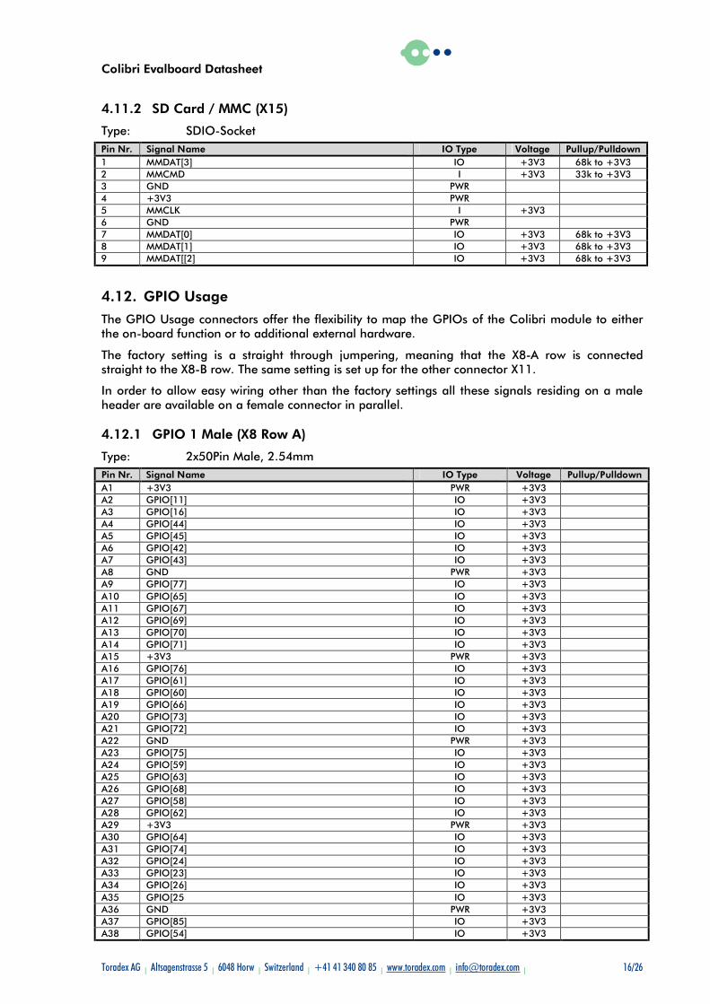
4.11.2 SD Card / MMC (X15)
Type: SDIO-Socket Pin Nr. Signal Name IO Type Voltage Pullup/Pulldown 1 MMDAT[3] IO +3V3 68k to +3V3 2 MMCMD I +3V3 33k to +3V3 3 GND PWR 4 +3V3 PWR 5 MMCLK I +3V3 6 GND PWR 7 MMDAT[0] IO +3V3 68k to +3V3 8 MMDAT[1] IO +3V3 68k to +3V3 9 MMDAT[[2] IO +3V3 68k to +3V3
4.12. GPIO Usage
The GPIO Usage connectors offer the flexibility to map the GPIOs of the Colibri module to either the on-board function or to additional external hardware.
The factory setting is a straight through jumpering, meaning that the X8-A row is connected straight to the X8-B row. The same setting is set up for the other connector X11.
In order to allow easy wiring other than the factory settings all these signals residing on a male header are available on a female connector in parallel.
4.12.1 GPIO 1 Male (X8 Row A)
Type: 2x50Pin Male, 2.54mm Pin Nr. Signal Name IO Type Voltage Pullup/Pulldown A1 +3V3 PWR +3V3 A2 GPIO[11] IO +3V3 A3 GPIO[16] IO +3V3 A4 GPIO[44] IO +3V3 A5 GPIO[45] IO +3V3 A6 GPIO[42] IO +3V3 A7 GPIO[43] IO +3V3 A8 GND PWR +3V3 A9 GPIO[77] IO +3V3 A10 GPIO[65] IO +3V3 A11 GPIO[67] IO +3V3 A12 GPIO[69] IO +3V3 A13 GPIO[70] IO +3V3 A14 GPIO[71] IO +3V3 A15 +3V3 PWR +3V3 A16 GPIO[76] IO +3V3 A17 GPIO[61] IO +3V3 A18 GPIO[60] IO +3V3 A19 GPIO[66] IO +3V3 A20 GPIO[73] IO +3V3 A21 GPIO[72] IO +3V3 A22 GND PWR +3V3 A23 GPIO[75] IO +3V3 A24 GPIO[59] IO +3V3 A25 GPIO[63] IO +3V3 A26 GPIO[68] IO +3V3 A27 GPIO[58] IO +3V3 A28 GPIO[62] IO +3V3 A29 +3V3 PWR +3V3 A30 GPIO[64] IO +3V3 A31 GPIO[74] IO +3V3 A32 GPIO[24] IO +3V3 A33 GPIO[23] IO +3V3 A34 GPIO[26] IO +3V3 A35 GPIO[25 IO +3V3 A36 GND PWR +3V3 A37 GPIO[85] IO +3V3 A38 GPIO[54] IO +3V3
Colibri Evalboard Datasheet
Toradex AG l Altsagenstrasse 5 l 6048 Horw l Switzerland l +41 41 340 80 85 l www.toradex.com l [email protected] l 17/26
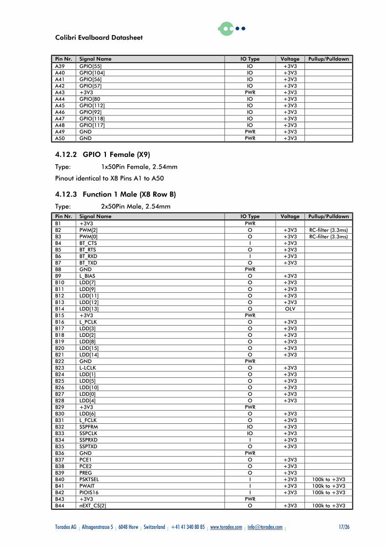
Pin Nr. Signal Name IO Type Voltage Pullup/Pulldown A39 GPIO[55] IO +3V3 A40 GPIO[104] IO +3V3 A41 GPIO[56] IO +3V3 A42 GPIO[57] IO +3V3 A43 +3V3 PWR +3V3 A44 GPIO[80 IO +3V3 A45 GPIO[112] IO +3V3 A46 GPIO[92] IO +3V3 A47 GPIO[118] IO +3V3 A48 GPIO[117] IO +3V3 A49 GND PWR +3V3 A50 GND PWR +3V3
4.12.2 GPIO 1 Female (X9)
Type: 1x50Pin Female, 2.54mm
Pinout identical to X8 Pins A1 to A50
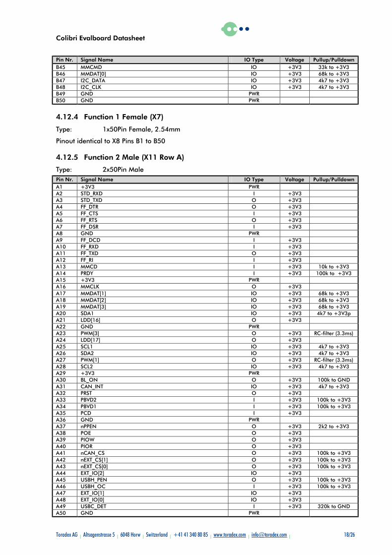
4.12.3 Function 1 Male (X8 Row B)
Type: 2x50Pin Male, 2.54mm Pin Nr. Signal Name IO Type Voltage Pullup/Pulldown B1 +3V3 PWR B2 PWM[2] O +3V3 RC-filter (3.3ms) B3 PWM[0] O +3V3 RC-filter (3.3ms) B4 BT_CTS I +3V3 B5 BT_RTS O +3V3 B6 BT_RXD I +3V3 B7 BT_TXD O +3V3 B8 GND PWR B9 L_BIAS O +3V3 B10 LDD[7] O +3V3 B11 LDD[9] O +3V3 B12 LDD[11] O +3V3 B13 LDD[12] O +3V3 B14 LDD[13] O OLV B15 +3V3 PWR B16 L_PCLK O +3V3 B17 LDD[3] O +3V3 B18 LDD[2] O +3V3 B19 LDD[8] O +3V3 B20 LDD[15] O +3V3 B21 LDD[14] O +3V3 B22 GND PWR B23 L-LCLK O +3V3 B24 LDD[1] O +3V3 B25 LDD[5] O +3V3 B26 LDD[10] O +3V3 B27 LDD[0] O +3V3 B28 LDD[4] O +3V3 B29 +3V3 PWR B30 LDD[6] O +3V3 B31 L_FCLK O +3V3 B32 SSPFRM IO +3V3 B33 SSPCLK IO +3V3 B34 SSPRXD I +3V3 B35 SSPTXD O +3V3 B36 GND PWR B37 PCE1 O +3V3 B38 PCE2 O +3V3 B39 PREG O +3V3 B40 PSKTSEL I +3V3 100k to +3V3 B41 PWAIT I +3V3 100k to +3V3 B42 PIOIS16 I +3V3 100k to +3V3 B43 +3V3 PWR B44 nEXT_CS[2] O +3V3 100k to +3V3
Colibri Evalboard Datasheet
Toradex AG l Altsagenstrasse 5 l 6048 Horw l Switzerland l +41 41 340 80 85 l www.toradex.com l [email protected] l 18/26
Pin Nr. Signal Name IO Type Voltage Pullup/Pulldown B45 MMCMD IO +3V3 33k to +3V3 B46 MMDAT[0] IO +3V3 68k to +3V3 B47 I2C_DATA IO +3V3 4k7 to +3V3 B48 I2C_CLK IO +3V3 4k7 to +3V3 B49 GND PWR B50 GND PWR
4.12.4 Function 1 Female (X7)
Type: 1x50Pin Female, 2.54mm
Pinout identical to X8 Pins B1 to B50
4.12.5 Function 2 Male (X11 Row A)
Type: 2x50Pin Male Pin Nr. Signal Name IO Type Voltage Pullup/Pulldown A1 +3V3 PWR A2 STD_RXD I +3V3 A3 STD_TXD O +3V3 A4 FF_DTR O +3V3 A5 FF_CTS I +3V3 A6 FF_RTS O +3V3 A7 FF_DSR I +3V3 A8 GND PWR A9 FF_DCD I +3V3 A10 FF_RXD I +3V3 A11 FF_TXD O +3V3 A12 FF_RI I +3V3 A13 MMCD I +3V3 10k to +3V3 A14 PRDY I +3V3 100k to +3V3 A15 +3V3 PWR A16 MMCLK O +3V3 A17 MMDAT[1] IO +3V3 68k to +3V3 A18 MMDAT[2] IO +3V3 68k to +3V3 A19 MMDAT[3] IO +3V3 68k to +3V3 A20 SDA1 IO +3V3 4k7 to +3V3p A21 LDD[16] O +3V3 A22 GND PWR A23 PWM[3] O +3V3 RC-filter (3.3ms) A24 LDD[17] O +3V3 A25 SCL1 IO +3V3 4k7 to +3V3 A26 SDA2 IO +3V3 4k7 to +3V3 A27 PWM[1] O +3V3 RC-filter (3.3ms) A28 SCL2 IO +3V3 4k7 to +3V3 A29 +3V3 PWR A30 BL_ON O +3V3 100k to GND A31 CAN_INT IO +3V3 4k7 to +3V3 A32 PRST O +3V3 A33 PBVD2 I +3V3 100k to +3V3 A34 PBVD1 I +3V3 100k to +3V3 A35 PCD I +3V3 A36 GND PWR A37 nPPEN O +3V3 2k2 to +3V3 A38 POE O +3V3 A39 PIOW O +3V3 A40 PIOR O +3V3 A41 nCAN_CS O +3V3 100k to +3V3 A42 nEXT_CS[1] O +3V3 100k to +3V3 A43 nEXT_CS[0] O +3V3 100k to +3V3 A44 EXT_IO[2] IO +3V3 A45 USBH_PEN O +3V3 100k to +3V3 A46 USBH_OC I +3V3 100k to +3V3 A47 EXT_IO[1] IO +3V3 A48 EXT_IO[0] IO +3V3 A49 USBC_DET I +3V3 320k to GND A50 GND PWR
Colibri Evalboard Datasheet
Toradex AG l Altsagenstrasse 5 l 6048 Horw l Switzerland l +41 41 340 80 85 l www.toradex.com l [email protected] l 19/26
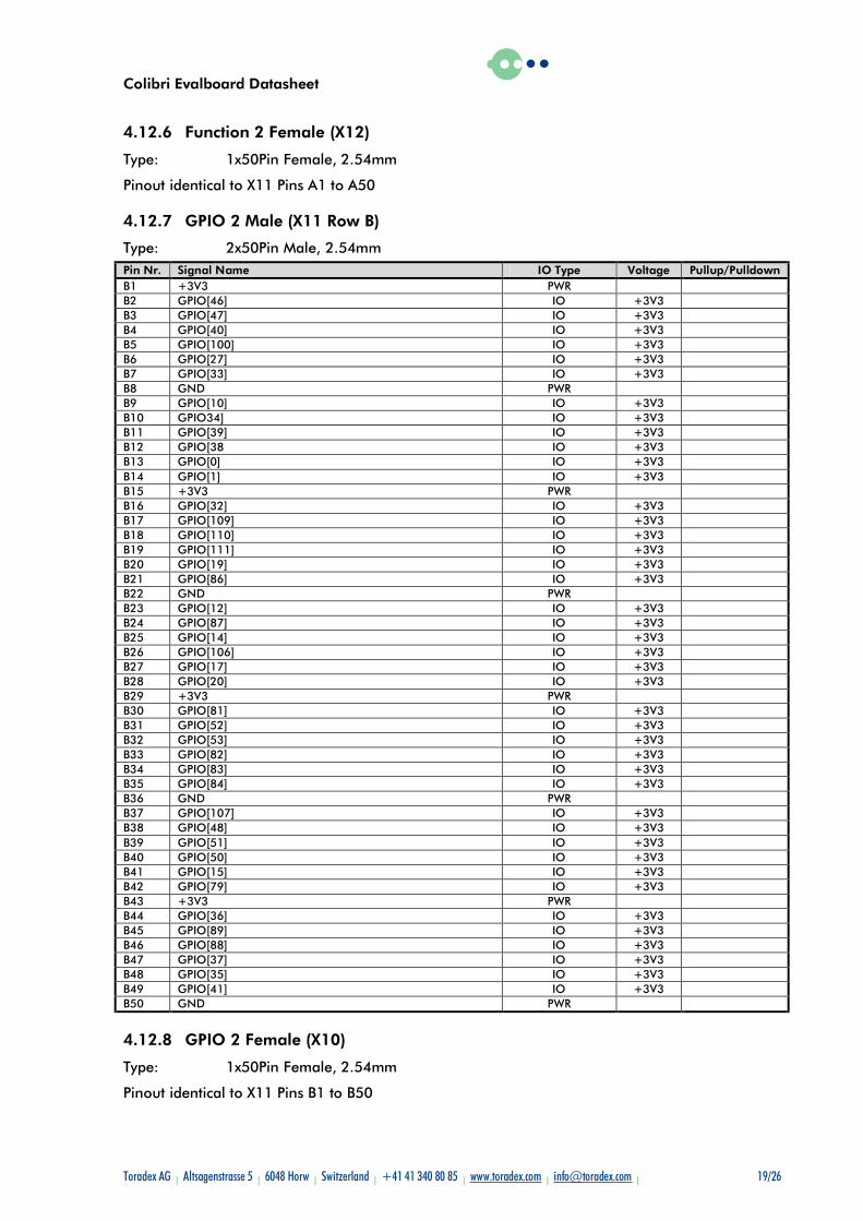
4.12.6 Function 2 Female (X12)
Type: 1x50Pin Female, 2.54mm
Pinout identical to X11 Pins A1 to A50
4.12.7 GPIO 2 Male (X11 Row B)
Type: 2x50Pin Male, 2.54mm Pin Nr. Signal Name IO Type Voltage Pullup/Pulldown B1 +3V3 PWR B2 GPIO[46] IO +3V3 B3 GPIO[47] IO +3V3 B4 GPIO[40] IO +3V3 B5 GPIO[100] IO +3V3 B6 GPIO[27] IO +3V3 B7 GPIO[33] IO +3V3 B8 GND PWR B9 GPIO[10] IO +3V3 B10 GPIO34] IO +3V3 B11 GPIO[39] IO +3V3 B12 GPIO[38 IO +3V3 B13 GPIO[0] IO +3V3 B14 GPIO[1] IO +3V3 B15 +3V3 PWR B16 GPIO[32] IO +3V3 B17 GPIO[109] IO +3V3 B18 GPIO[110] IO +3V3 B19 GPIO[111] IO +3V3 B20 GPIO[19] IO +3V3 B21 GPIO[86] IO +3V3 B22 GND PWR B23 GPIO[12] IO +3V3 B24 GPIO[87] IO +3V3 B25 GPIO[14] IO +3V3 B26 GPIO[106] IO +3V3 B27 GPIO[17] IO +3V3 B28 GPIO[20] IO +3V3 B29 +3V3 PWR B30 GPIO[81] IO +3V3 B31 GPIO[52] IO +3V3 B32 GPIO[53] IO +3V3 B33 GPIO[82] IO +3V3 B34 GPIO[83] IO +3V3 B35 GPIO[84] IO +3V3 B36 GND PWR B37 GPIO[107] IO +3V3 B38 GPIO[48] IO +3V3 B39 GPIO[51] IO +3V3 B40 GPIO[50] IO +3V3 B41 GPIO[15] IO +3V3 B42 GPIO[79] IO +3V3 B43 +3V3 PWR B44 GPIO[36] IO +3V3 B45 GPIO[89] IO +3V3 B46 GPIO[88] IO +3V3 B47 GPIO[37] IO +3V3 B48 GPIO[35] IO +3V3 B49 GPIO[41] IO +3V3 B50 GND PWR
4.12.8 GPIO 2 Female (X10)
Type: 1x50Pin Female, 2.54mm
Pinout identical to X11 Pins B1 to B50
Colibri Evalboard Datasheet
Toradex AG l Altsagenstrasse 5 l 6048 Horw l Switzerland l +41 41 340 80 85 l www.toradex.com l [email protected] l 20/26
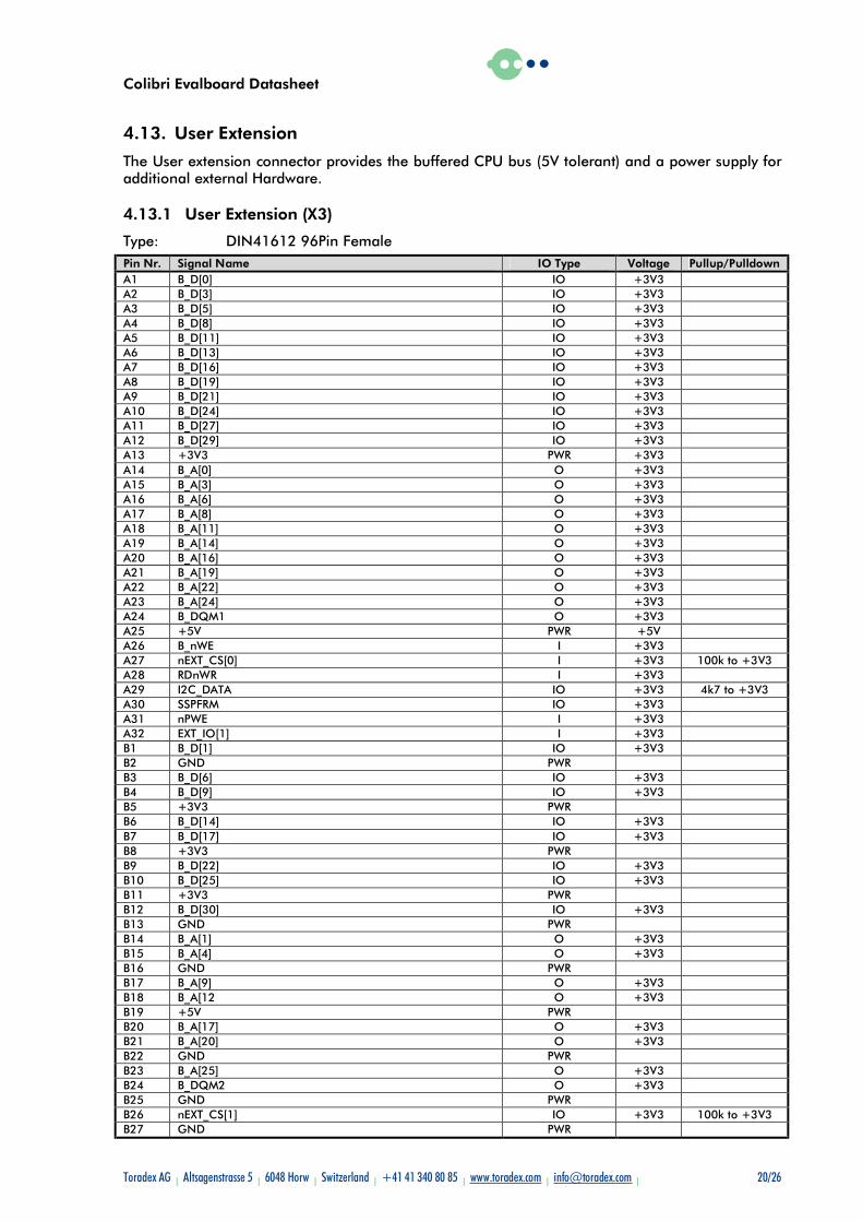
4.13. User Extension
The User extension connector provides the buffered CPU bus (5V tolerant) and a power supply for additional external Hardware.
4.13.1 User Extension (X3)
Type: DIN41612 96Pin Female Pin Nr. Signal Name IO Type Voltage Pullup/Pulldown A1 B_D[0] IO +3V3 A2 B_D[3] IO +3V3 A3 B_D[5] IO +3V3 A4 B_D[8] IO +3V3 A5 B_D[11] IO +3V3 A6 B_D[13] IO +3V3 A7 B_D[16] IO +3V3 A8 B_D[19] IO +3V3 A9 B_D[21] IO +3V3 A10 B_D[24] IO +3V3 A11 B_D[27] IO +3V3 A12 B_D[29] IO +3V3 A13 +3V3 PWR +3V3 A14 B_A[0] O +3V3 A15 B_A[3] O +3V3 A16 B_A[6] O +3V3 A17 B_A[8] O +3V3 A18 B_A[11] O +3V3 A19 B_A[14] O +3V3 A20 B_A[16] O +3V3 A21 B_A[19] O +3V3 A22 B_A[22] O +3V3 A23 B_A[24] O +3V3 A24 B_DQM1 O +3V3 A25 +5V PWR +5V A26 B_nWE I +3V3 A27 nEXT_CS[0] I +3V3 100k to +3V3 A28 RDnWR I +3V3 A29 I2C_DATA IO +3V3 4k7 to +3V3 A30 SSPFRM IO +3V3 A31 nPWE I +3V3 A32 EXT_IO[1] I +3V3 B1 B_D[1] IO +3V3 B2 GND PWR B3 B_D[6] IO +3V3 B4 B_D[9] IO +3V3 B5 +3V3 PWR B6 B_D[14] IO +3V3 B7 B_D[17] IO +3V3 B8 +3V3 PWR B9 B_D[22] IO +3V3 B10 B_D[25] IO +3V3 B11 +3V3 PWR B12 B_D[30] IO +3V3 B13 GND PWR B14 B_A[1] O +3V3 B15 B_A[4] O +3V3 B16 GND PWR B17 B_A[9] O +3V3 B18 B_A[12 O +3V3 B19 +5V PWR B20 B_A[17] O +3V3 B21 B_A[20] O +3V3 B22 GND PWR B23 B_A[25] O +3V3 B24 B_DQM2 O +3V3 B25 GND PWR B26 nEXT_CS[1] IO +3V3 100k to +3V3 B27 GND PWR
Colibri Evalboard Datasheet
Toradex AG l Altsagenstrasse 5 l 6048 Horw l Switzerland l +41 41 340 80 85 l www.toradex.com l [email protected] l 21/26
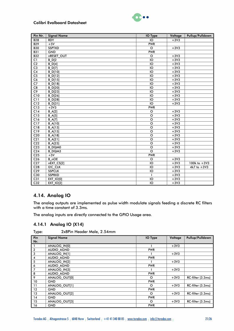
Pin Nr. Signal Name IO Type Voltage Pullup/Pulldown B28 RDY IO +3V3 B29 +5V PWR B30 SSPTXD O +3V3 B31 GND PWR B32 nRESET_OUT O +3V3 C1 B_D[2 IO +3V3 C2 B_D[4] IO +3V3 C3 B_D[7] IO +3V3 C4 B_D[10] IO +3V3 C5 B_D[12] IO +3V3 C6 B_D[15] IO +3V3 C7 B_D[18] IO +3V3 C8 B_D[20] IO +3V3 C9 B_D[23] IO +3V3 C10 B_D[26] IO +3V3 C11 B_D[28] IO +3V3 C12 B_D[31] IO +3V3 C13 +3V3 PWR C14 B_A[2] O +3V3 C15 B_A[5] O +3V3 C16 B_A[7] O +3V3 C17 B_A[10] O +3V3 C18 B_A[13] O +3V3 C19 B_A[15] O +3V3 C20 B_A[18] O +3V3 C21 B_A[21] O +3V3 C22 B_A[23] O +3V3 C23 B_DQM0 O +3V3 C24 B_DQM3 O +3V3 C25 +5V PWR C26 B_nOE O +3V3 C27 nEXT_CS[2] IO +3V3 100k to +3V3 C28 I2C_CLK IO +3V3 4k7 to +3V3 C29 SSPCLK IO +3V3 C30 SSPRXD I +3V3 C31 EXT_IO[0] IO +3V3 C32 EXT_IO[2] IO +3V3
4.14. Analog IO
The analog outputs are implemented as pulse width modulate signals feeding a discrete RC filters with a time constant of 3.3ms.
The analog inputs are directly connected to the GPIO Usage area.
4.14.1 Analog IO (X14)
Type: 2x8Pin Header Male, 2.54mm Pin Nr.
Signal Name IO Type Voltage Pullup/Pulldown
1 ANALOG_IN[0] I +3V3 2 AUDIO_AGND PWR 3 ANALOG_IN[1] I +3V3 4 AUDIO_AGND PWR 5 ANALOG_IN[2] I +3V3 6 AUDIO_AGND PWR 7 ANALOG_IN[3] I +3V3 8 AUDIO_AGND PWR 9 ANALOG_OUT[0] O +3V3 RC-filter (3.3ms) 10 GND PWR 11 ANALOG_OUT[1] O +3V3 RC-filter (3.3ms) 12 GND PWR 13 ANALOG_OUT[2] O +3V3 RC-filter (3.3ms) 14 GND PWR 15 ANALOG_OUT[3] O +3V3 RC-filter (3.3ms) 16 GND PWR
Colibri Evalboard Datasheet
Toradex AG l Altsagenstrasse 5 l 6048 Horw l Switzerland l +41 41 340 80 85 l www.toradex.com l [email protected] l 22/26
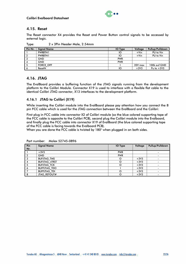
4.15. Reset
The Reset connector X4 provides the Reset and Power Button control signals to be accessed by external logic.
Type: 2 x 3Pin Header Male, 2.54mm Pin Nr. Signal Name IO Type Voltage Pullup/Pulldown 1 PWRBTN1 IO +Vin PU to Vin 2 PWRBTN1 IO +Vin PU to Vin 3 GND PWR 4 GND PWR 5 FORCE_OFF I 20V max 100k auf GND 6 ResetN IO +3V3 Pu to +3V3
4.16. JTAG
The EvalBoard provides a buffering function of the JTAG signals running from the development platform to the Colibri Module. Connector X19 is used to interface with a flexible flat cable to the identical Colibri JTAG connector, X13 interfaces to the development platform.
4.16.1 JTAG to Colibri (X19)
While inserting the Colibri module into the EvalBoard please pay attention how you connect the 8 pin FCC cable which is used for the JTAG connection between the EvalBoard and the Colibri:
First plug in FCC cable into connector X2 of Colibri module (so the blue colored supporting tape of the FCC cable is opposite to the Colibri PCB), second plug the Colibri module into the Evalboard, and finally plug the FCC cable into connector X19 of EvalBoard (the blue colored supporting tape of the FCC cable is facing towards the Evalboard PCB). When you are done the FCC cable is twisted by 180° when plugged in on both sides.
Part number: Molex 52745-0896 Pin Nr.
Signal Name IO Type Voltage Pullup/Pulldown
1 +3V3 PWR - 2 GND PWR - 3 BUFJTAG_TMS O +3V3 - 4 BUFJTAG_nTRST O +3V3 - 5 BUFJTAG_TCK O +3V3 - 6 BUFFJTAG_TDO I +3V3 - 7 BUFFJTAG_TDI O +3V3 - 8 JTAG_RSTOUT# O +3V3 -
Colibri Evalboard Datasheet
Toradex AG l Altsagenstrasse 5 l 6048 Horw l Switzerland l +41 41 340 80 85 l www.toradex.com l [email protected] l 23/26
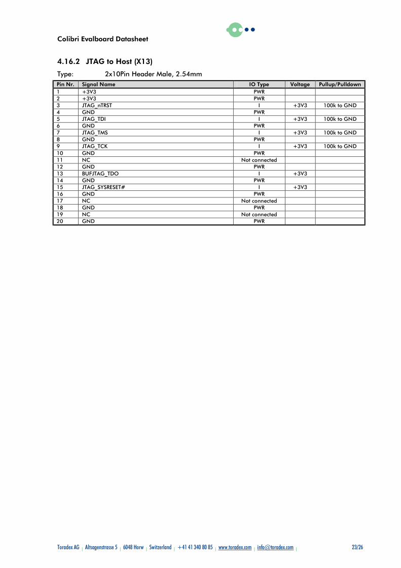
4.16.2 JTAG to Host (X13)
Type: 2x10Pin Header Male, 2.54mm Pin Nr. Signal Name IO Type Voltage Pullup/Pulldown 1 +3V3 PWR 2 +3V3 PWR 3 JTAG_nTRST I +3V3 100k to GND 4 GND PWR 5 JTAG_TDI I +3V3 100k to GND 6 GND PWR 7 JTAG_TMS I +3V3 100k to GND 8 GND PWR 9 JTAG_TCK I +3V3 100k to GND 10 GND PWR 11 NC Not connected 12 GND PWR 13 BUFJTAG_TDO I +3V3 14 GND PWR 15 JTAG_SYSRESET# I +3V3 16 GND PWR 17 NC Not connected 18 GND PWR 19 NC Not connected 20 GND PWR
Colibri Evalboard Datasheet
Toradex AG l Altsagenstrasse 5 l 6048 Horw l Switzerland l +41 41 340 80 85 l www.toradex.com l [email protected] l 24/26
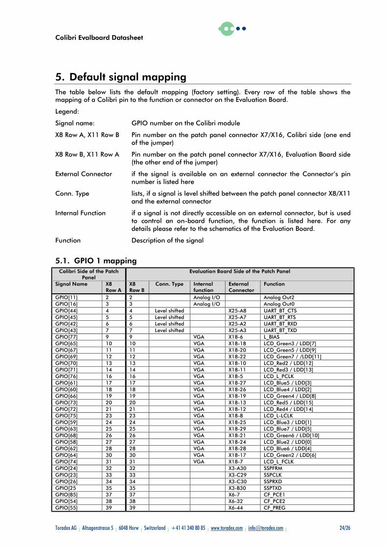
5. Default signal mapping The table below lists the default mapping (factory setting). Every row of the table shows the mapping of a Colibri pin to the function or connector on the Evaluation Board.
Legend:
Signal name: GPIO number on the Colibri module
X8 Row A, X11 Row B Pin number on the patch panel connector X7/X16, Colibri side (one end of the jumper)
X8 Row B, X11 Row A Pin number on the patch panel connector X7/X16, Evaluation Board side (the other end of the jumper)
External Connector if the signal is available on an external connector the Connector’s pin number is listed here
Conn. Type lists, if a signal is level shifted between the patch panel connector X8/X11 and the external connector
Internal Function if a signal is not directly accessible on an external connector, but is used to control an on-board function, the function is listed here. For any details please refer to the schematics of the Evaluation Board.
Function Description of the signal
5.1. GPIO 1 mapping Colibri Side of the Patch
Panel Evaluation Board Side of the Patch Panel
Signal Name X8 Row A
X8 Row B
Conn. Type Internal function
External Connector
Function
GPIO[11] 2 2 Analog I/O Analog Out2 GPIO[16] 3 3 Analog I/O Analog Out0 GPIO[44] 4 4 Level shifted X25-A8 UART_BT_CTS GPIO[45] 5 5 Level shifted X25-A7 UART_BT_RTS GPIO[42] 6 6 Level shifted X25-A2 UART_BT_RXD GPIO[43] 7 7 Level shifted X25-A3 UART_BT_TXD GPIO[77] 9 9 VGA X18-6 L_BIAS GPIO[65] 10 10 VGA X18-18 LCD_Green3 / LDD[7] GPIO[67] 11 11 VGA X18-20 LCD_Green5 / LDD[9] GPIO[69] 12 12 VGA X18-22 LCD_Green7 / /LDD[11] GPIO[70] 13 13 VGA X18-10 LCD_Red2 / LDD[12] GPIO[71] 14 14 VGA X18-11 LCD_Red3 / LDD[13] GPIO[76] 16 16 VGA X18-5 LCD_L_PCLK GPIO[61] 17 17 VGA X18-27 LCD_Blue5 / LDD[3] GPIO[60] 18 18 VGA X18-26 LCD_Blue4 / LDD[2] GPIO[66] 19 19 VGA X18-19 LCD_Green4 / LDD[8] GPIO[73] 20 20 VGA X18-13 LCD_Red5 / LDD[15] GPIO[72] 21 21 VGA X18-12 LCD_Red4 / LDD[14] GPIO[75] 23 23 VGA X18-8 LCD_L-LCLK GPIO[59] 24 24 VGA X18-25 LCD_Blue3 / LDD[1] GPIO[63] 25 25 VGA X18-29 LCD_Blue7 / LDD[5] GPIO[68] 26 26 VGA X18-21 LCD_Green6 / LDD[10] GPIO[58] 27 27 VGA X18-24 LCD_Blue2 / LDD[0] GPIO[62] 28 28 VGA X18-28 LCD_Blue6 / LDD[4] GPIO[64] 30 30 VGA X18-17 LCD_Green2 / LDD[6] GPIO[74] 31 31 VGA X18-7 LCD_L_FCLK GPIO[24] 32 32 X3-A30 SSPFRM GPIO[23] 33 33 X3-C29 SSPCLK GPIO[26] 34 34 X3-C30 SSPRXD GPIO[25 35 35 X3-B30 SSPTXD GPIO[85] 37 37 X6-7 CF_PCE1 GPIO[54] 38 38 X6-32 CF_PCE2 GPIO[55] 39 39 X6-44 CF_PREG
Colibri Evalboard Datasheet
Toradex AG l Altsagenstrasse 5 l 6048 Horw l Switzerland l +41 41 340 80 85 l www.toradex.com l [email protected] l 25/26
Colibri Side of the Patch Panel
Evaluation Board Side of the Patch Panel
Signal Name X8 Row A
X8 Row B
Conn. Type Internal function
External Connector
Function
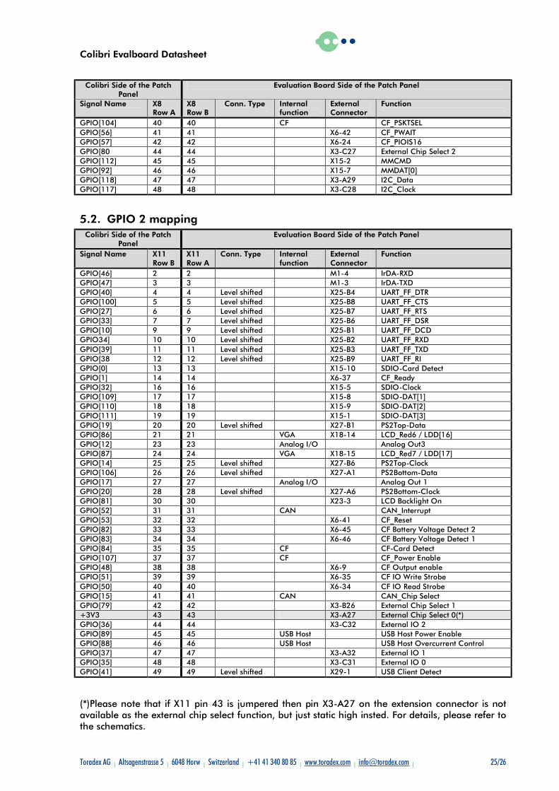
GPIO[104] 40 40 CF CF_PSKTSEL GPIO[56] 41 41 X6-42 CF_PWAIT GPIO[57] 42 42 X6-24 CF_PIOIS16 GPIO[80 44 44 X3-C27 External Chip Select 2 GPIO[112] 45 45 X15-2 MMCMD GPIO[92] 46 46 X15-7 MMDAT[0] GPIO[118] 47 47 X3-A29 I2C_Data GPIO[117] 48 48 X3-C28 I2C_Clock
5.2. GPIO 2 mapping Colibri Side of the Patch
Panel Evaluation Board Side of the Patch Panel
Signal Name X11 Row B
X11 Row A
Conn. Type Internal function
External Connector
Function
GPIO[46] 2 2 M1-4 IrDA-RXD GPIO[47] 3 3 M1-3 IrDA-TXD GPIO[40] 4 4 Level shifted X25-B4 UART_FF_DTR GPIO[100] 5 5 Level shifted X25-B8 UART_FF_CTS GPIO[27] 6 6 Level shifted X25-B7 UART_FF_RTS GPIO[33] 7 7 Level shifted X25-B6 UART_FF_DSR GPIO[10] 9 9 Level shifted X25-B1 UART_FF_DCD GPIO34] 10 10 Level shifted X25-B2 UART_FF_RXD GPIO[39] 11 11 Level shifted X25-B3 UART_FF_TXD GPIO[38 12 12 Level shifted X25-B9 UART_FF_RI GPIO[0] 13 13 X15-10 SDIO-Card Detect GPIO[1] 14 14 X6-37 CF_Ready GPIO[32] 16 16 X15-5 SDIO-Clock GPIO[109] 17 17 X15-8 SDIO-DAT[1] GPIO[110] 18 18 X15-9 SDIO-DAT[2] GPIO[111] 19 19 X15-1 SDIO-DAT[3] GPIO[19] 20 20 Level shifted X27-B1 PS2Top-Data GPIO[86] 21 21 VGA X18-14 LCD_Red6 / LDD[16] GPIO[12] 23 23 Analog I/O Analog Out3 GPIO[87] 24 24 VGA X18-15 LCD_Red7 / LDD[17] GPIO[14] 25 25 Level shifted X27-B6 PS2Top-Clock GPIO[106] 26 26 Level shifted X27-A1 PS2Bottom-Data GPIO[17] 27 27 Analog I/O Analog Out 1 GPIO[20] 28 28 Level shifted X27-A6 PS2Bottom-Clock GPIO[81] 30 30 X23-3 LCD Backlight On GPIO[52] 31 31 CAN CAN_Interrupt GPIO[53] 32 32 X6-41 CF_Reset GPIO[82] 33 33 X6-45 CF Battery Voltage Detect 2 GPIO[83] 34 34 X6-46 CF Battery Voltage Detect 1 GPIO[84] 35 35 CF CF-Card Detect GPIO[107] 37 37 CF CF_Power Enable GPIO[48] 38 38 X6-9 CF Output enable GPIO[51] 39 39 X6-35 CF IO Write Strobe GPIO[50] 40 40 X6-34 CF IO Read Strobe GPIO[15] 41 41 CAN CAN_Chip Select GPIO[79] 42 42 X3-B26 External Chip Select 1 +3V3 43 43 X3-A27 External Chip Select 0(*) GPIO[36] 44 44 X3-C32 External IO 2 GPIO[89] 45 45 USB Host USB Host Power Enable GPIO[88] 46 46 USB Host USB Host Overcurrent Control GPIO[37] 47 47 X3-A32 External IO 1 GPIO[35] 48 48 X3-C31 External IO 0 GPIO[41] 49 49 Level shifted X29-1 USB Client Detect
(*)Please note that if X11 pin 43 is jumpered then pin X3-A27 on the extension connector is not available as the external chip select function, but just static high insted. For details, please refer to the schematics.
Colibri Evalboard Datasheet
Toradex AG l Altsagenstrasse 5 l 6048 Horw l Switzerland l +41 41 340 80 85 l www.toradex.com l [email protected] l 26/26
Disclaimer:
Toradex AG reserves the right to make changes, without notice, to any product, including circuits and/or software described or contained in this datasheet.
Toradex AG assumes no responsibility or liability for the use of the described product(s), conveys no license or title under any patent, copyright, or mask work rights to these products, and makes no representations or warranties that these products are free from patent, copyright, or mask work right infringement, unless otherwise specified.
Trademark Acknowledgement:
Brand and product names are trademarks or registered trademarks of their respective owners.