journal of information, knowledge and ... sssc will modulate much more sensitive t series capacitor....
TRANSCRIPT

JOURNAL OF INFORMATION, KNOWLEDGE AND
ELECTRICAL ENGINEERING
COORDINATED CONTROL OF HYBRID SERIES
CAPACITIVE COMPENSATION FOR DAMPING
POWER SYSTEM OSCILLATIONS IN DFIG BASED
1 A.KIRUTHIKA,
2 DR.V.GOPALAKRISHNAN,
1 PG Scholar2 Asso.prof/Dept.of EEE
3 Ph.D scholar/Dept.of EEE
[email protected], [email protected], [email protected] ABSTRACT— The recently proposed
based wind farms combined with a phase imbalanced hybrid series capacitive compensation scheme for
damping power system oscillations, phase imbalanced series capacitive compensation concept has been shown
to be effective in enhancing power system dynamics as it has the potential of damping power swing as well as
sub-synchronous resonance oscillations
duringsystem disturbances in wind energy generation
exchanged between the electrical and mechanical sides of the turbine
reduction of the growing torsional stresses at SSR mode.
scheme, where two phases are compensated by fixed series capacitors (C) and the third phase is compensated
by an SSSC in series with a fixed capacitor (Cc). The effectiveness of the scheme in damping power system
oscillations during system faults at different loading conditions is evaluated using the MATLAB simulation
program.
I.INTRODUCTION FLEXIBLE ac transmission system (FACTS) technologyprovides unprecedented way for controlling transmissiongrids and increasing transmission capacity [1]–[3]. FACTS controllershave the flexibility of controlling both real and reactivepower which could provide an excellent capability for improvingpower system dynamics. Several studies have investigated thepotusing this capability in enhancing power system dynamics,e.g., damping of power oscillations and sub-synchronousresonance. The use of thyristor controlled series capacitor(TCSC), static synchronous compensator (STATCOM), and static synchronous seriescompensator (SSSC) have been the subjects of several studies evaluating their respective effectiveness in enhancing power system dynamics [4]–[17]. They are “hybrid” series compensation schemes, where the series capacitive compensation in one phase is created using a single-phase TCSC (Scheme I) or a single-phase SSSC (Scheme II) in fixed capacitor (Cc), and the other two phases are compensated by fixed series capacitors (C). The TCSC and SSSC controls are initially set such that their equivalent compensations at the power frequency combined with the fixed capacitor yield a resultant compensation equal to the other two phases. Thus, the phase balance is maintained at the power frequency while at any other frequency, a phase
JOURNAL OF INFORMATION, KNOWLEDGE AND RESEARCH IN
ELECTRICAL ENGINEERING
COORDINATED CONTROL OF HYBRID SERIES
CAPACITIVE COMPENSATION FOR DAMPING
POWER SYSTEM OSCILLATIONS IN DFIG BASED
WIND FARM
DR.V.GOPALAKRISHNAN, 3
IMMANUEL JOHN SAMUEL
PG Scholar/Dept. of EEE,GCT, Coimbatore-13
Asso.prof/Dept.of EEE, GCT, Coimbatore-13
scholar/Dept.of EEE, GCT,Coimbatore-13
[email protected], [email protected], [email protected]
The recently proposed scheme investigates the potential use of supplemental controls of DFIG
based wind farms combined with a phase imbalanced hybrid series capacitive compensation scheme for
phase imbalanced series capacitive compensation concept has been shown
hancing power system dynamics as it has the potential of damping power swing as well as
synchronous resonance oscillations in wind Farm.The hybrid scheme creates a phase imbalance
in wind energy generation. The phase imbalance causes a suppression of the energy
exchanged between the electrical and mechanical sides of the turbine-generator and, therefore results in
reduction of the growing torsional stresses at SSR mode. A hybrid scheme is a series capacitive compensation
scheme, where two phases are compensated by fixed series capacitors (C) and the third phase is compensated
by an SSSC in series with a fixed capacitor (Cc). The effectiveness of the scheme in damping power system
oscillations during system faults at different loading conditions is evaluated using the MATLAB simulation
FLEXIBLE ac transmission system (FACTS) technologyprovides unprecedented way for
iongrids and increasing [3]. FACTS
controllershave the flexibility of controlling both real and reactivepower which could provide an excellent capability for improvingpower system dynamics. Several studies have investigated thepotential of using this capability in enhancing power system dynamics,e.g., damping of power oscillations and
synchronousresonance. The use of thyristor controlled series capacitor(TCSC), static synchronous compensator (STATCOM), and static synchronous
riescompensator (SSSC) have been the subjects of several studies evaluating their respective effectiveness in enhancing power system dynamics
They are “hybrid” series compensation schemes, where the series capacitive compensation in one
phase TCSC (Scheme phase SSSC (Scheme II) in series with a
fixed capacitor (Cc), and the other two phases are compensated by fixed series capacitors (C). The TCSC and SSSC controls are initially set such that
ivalent compensations at the power frequency combined with the fixed capacitor yield a resultant compensation equal to the other two phases. Thus, the phase balance is maintained at the power frequency while at any other frequency, a phase
imbalance is created. To further enhance power oscillations damping, the TCSC and SSSC are equipped with supplementary controllers.
Fig.1 Hybrid series compensation Fig. 1 shows two schemes for a phaseimbalanced series capacitive compensation. The“hybrid” series compensation schemes, where the series capacitive compensation in one phase is created by using a single-phase TCSC (Scheme I) or a single-phase SSSC (Scheme II) in series with a fixed capacitor , and the other two phases are compensated by fixed series capacitors (C). The TCSC and SSSC controls are initially set so that their equivalent compensations at the power frequency, combinedwith the fixed capacitor, yield resulting compensation equal to the other two phases. Thus, phase balance is maintained at the power frequency while at any other frequency, phase imbalance is created. To further enhance power oscillation damping, the TCSC and SSSC are equipped with supplementary controllers.
RESEARCH IN
COORDINATED CONTROL OF HYBRID SERIES
CAPACITIVE COMPENSATION FOR DAMPING
POWER SYSTEM OSCILLATIONS IN DFIG BASED
IMMANUEL JOHN SAMUEL
[email protected], [email protected], [email protected]
supplemental controls of DFIG-
based wind farms combined with a phase imbalanced hybrid series capacitive compensation scheme for
phase imbalanced series capacitive compensation concept has been shown
hancing power system dynamics as it has the potential of damping power swing as well as
The hybrid scheme creates a phase imbalance
causes a suppression of the energy
generator and, therefore results in
scheme is a series capacitive compensation
scheme, where two phases are compensated by fixed series capacitors (C) and the third phase is compensated
by an SSSC in series with a fixed capacitor (Cc). The effectiveness of the scheme in damping power system
oscillations during system faults at different loading conditions is evaluated using the MATLAB simulation
ated. To further enhance power oscillations damping, the TCSC and SSSC are equipped with supplementary controllers.
Fig.1 Hybrid series compensation
Fig. 1 shows two schemes for a phase-imbalanced series capacitive compensation. They are “hybrid” series compensation schemes, where the series capacitive compensation in one phase is
phase TCSC (Scheme I) or phase SSSC (Scheme II) in series with a
fixed capacitor , and the other two phases are ted by fixed series capacitors (C). The
TCSC and SSSC controls are initially set so that their equivalent compensations at the power frequency, combinedwith the fixed capacitor, yield resulting compensation equal to the other two phases. Thus,
e is maintained at the power frequency while at any other frequency, phase imbalance is created. To further enhance power oscillation damping, the TCSC and SSSC are equipped with
JOURNAL OF INFORMATION, KNOWLEDGE AND
ELECTRICAL ENGINEERING
II.SERIES COMPENSATION SCHEME
The SSSC control is initially set such that its equivalent compensation at the power frequency combined with the fixed capacitor Cc yields a resultant compensation equal to the other two phases. Thus, the phase balance is maintained at the power frequency whereas at any other frequency a phase imbalance is created. In this paper, a single-phase three-level VSC based on sinusoidal pulse width modulation (SPWM) is built up in the Simulink model of the singleSSSC. This structure is suitable for high power applications as, when compared to a twostructure, it provides less harmonics, lower switch blocking voltages and lower switching losses.1) At the power frequency, the series reactances between buses X and Y in Fig. 1 in phases a,b and c are given by
Xa=Xb=�
����
Xc=�
�����-jXsssco (2)
Where -jXsssco is the effective capacitive reactance ofthe SSSC at the power frequency so that X2) During any other frequency, fc
Xc=�
�����-jXsssco-j∆Xsssc.
The first terms in (2) and (3) are different because of the difference in frequency. The third term in (3) represents the change in effective capacitive reactance of the SSSC due to the action of the SSSC supplementary controller. These presentedwould definitely be economically attractive when compared with a full three-phase TCSC or SSSC, which have been used/proposed for power swings and subsynchronous resonance oscillations damping. Furthermore, reducing the number of thyristor valves and VSC to one-third will also have a positive impact one equipment reliability.
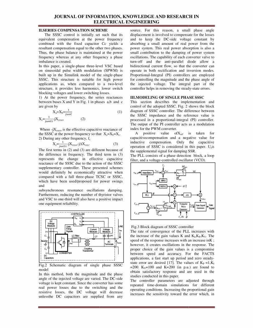
Fig.2 Schematic diagram of single phase SSSC model In this method, both the magnitude and the phase angle of the injected voltage are varied. The DCvoltage is kept constant. Since the converter has some real power losses due to the switching and the resistive losses, the DC voltage will decrease unlessthe DC capacitors are supplied from any
JOURNAL OF INFORMATION, KNOWLEDGE AND RESEARCH IN
ELECTRICAL ENGINEERING
SERIES COMPENSATION SCHEME
C control is initially set such that its equivalent compensation at the power frequency combined with the fixed capacitor Cc yields a resultant compensation equal to the other two phases. Thus, the phase balance is maintained at the power
s at any other frequency a phase
level VSC based on sinusoidal pulse width modulation (SPWM) is
the single-phase SSSC. This structure is suitable for high power
plications as, when compared to a two-level structure, it provides less harmonics, lower switch blocking voltages and lower switching losses. 1) At the power frequency, the series reactances between buses X and Y in Fig. 1 in phases a,b and c
(1)
is the effective capacitive reactance of the SSSC at the power frequency so that Xa=Xb=Xc.
. (3)
The first terms in (2) and (3) are different because of the difference in frequency. The third term in (3) represents the change in effective capacitive reactance of the SSSC due to the action of the SSSC supplementary controller. These presented schemes would definitely be economically attractive when
phase TCSC or SSSC, which have been used/proposed for power swings
subsynchronous resonance oscillations damping. Furthermore, reducing the number of thyristor valves
third will also have a positive impact
Fig.2 Schematic diagram of single phase SSSC
In this method, both the magnitude and the phase angle of the injected voltage are varied. The DC-side voltage is kept constant. Since the converter has some real power losses due to the switching and the resistive losses, the DC voltage will decrease
ssthe DC capacitors are supplied from any
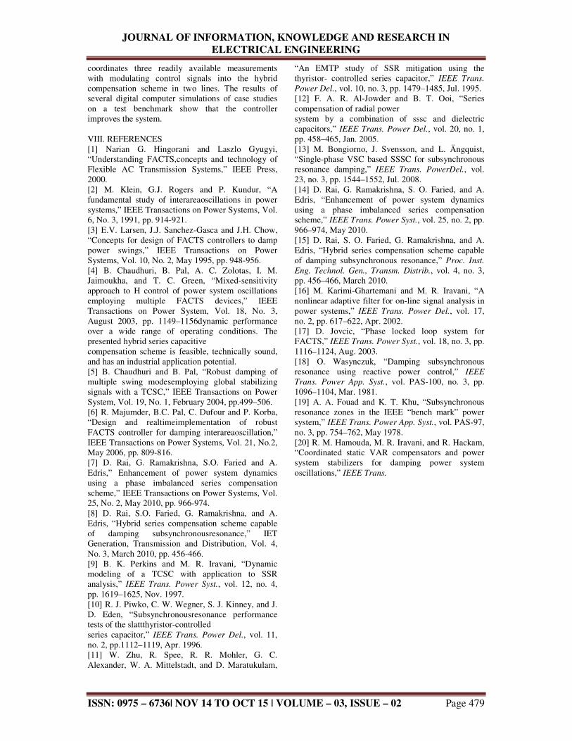
source. For this reason, a small phase angle displacement is involved to compensate for the losses and to keep the DC-side voltage constant by absorbing a small amount of real power from the power system. This real power absorption is also a small contribution to the damping of power system oscillations. The capability of each converter valve to turn-off and the anti-parallel diode allow a bidirectional current flow, so that the converter can operate in both rectification and inversion modes. Proportional-Integral (PI) controllers are employed for controlling the magnitude and the phase angle of the injected voltage. The integral part of the controller helps in removing the steady III.MODELING OF SINGLE PHASE SSSCThis section describes the implementation and control of the adopted SSSC. Fig. 2 shows the block diagram of SSSC controller. The difference between the SSSC impedance and the reference value is processed in a proportional-integral (PI) controThe output of the PI controller acts as a modulation index for the PWM converter. A positive value ofXref is taken for capacitivecompensation and a negative value for inductive compensation. Only the capacitive operation of SSSC is considered in this paper. Uthe supplemental signal for damping SSR.The PLL consists of a phase detection block, a loop filter, and a voltage-controlled oscillator (VCO).
Fig.3 Block diagram of SSSC controllerThe rate of convergence of the PLL increases with the increase of the gain values K and speed of the response increases with an increase inhowever, it creates oscillations in the response. The proper choice of the gain values is a compromise between speed and accuracy. For the FACTS applications, a fast start up period and zero steadystate error are desired [17]. The values of=200, KV=100 and K=200 (in p.u.) are found to obtain satisfactory response and are studies conducted in this paper. The controller parameters are adjusted through repeated time-domain simulations for different operating conditions. Increasing the proportional gain increases the sensitivity toward the error which, in
RESEARCH IN
source. For this reason, a small phase angle displacement is involved to compensate for the losses
side voltage constant by absorbing a small amount of real power from the
power absorption is also a small contribution to the damping of power system oscillations. The capability of each converter valve to
parallel diode allow a bidirectional current flow, so that the converter can
cation and inversion modes. Integral (PI) controllers are employed
for controlling the magnitude and the phase angle of the injected voltage. The integral part of the controller helps in removing the steady-state errors.
E PHASE SSSC This section describes the implementation and control of the adopted SSSC. Fig. 2 shows the block diagram of SSSC controller. The difference between the SSSC impedance and the reference value is
integral (PI) controller. The output of the PI controller acts as a modulation
is taken for capacitivecompensation and a negative value for inductive compensation. Only the capacitive operation of SSSC is considered in this paper. Usis the supplemental signal for damping SSR. The PLL consists of a phase detection block, a loop
controlled oscillator (VCO).
Block diagram of SSSC controller The rate of convergence of the PLL increases with
and KI,KP,KV. The speed of the response increases with an increase inK ;
it creates oscillations in the response. The proper choice of the gain values is a compromise between speed and accuracy. For the FACTS
period and zero steady-state error are desired [17]. The values of KP =1,KI
200 (in p.u.) are found to n satisfactory response and are used in the
The controller parameters are adjusted through domain simulations for different
operating conditions. Increasing the proportional gain increases the sensitivity toward the error which, in

JOURNAL OF INFORMATION, KNOWLEDGE AND
ELECTRICAL ENGINEERING
turn, increases the response overshoot, while increasing the integral gain decreases the steadyerror at a cost of an increase in settling time. Thus, the choices of these gains are made so that fast settling time and minimum overshoot (less than 10%) for a step change in input are achieved. IV.WORK BENCH To demonstrate the effectiveness of the proposedcoordinated control of Scheme II in power system oscillations damping, the system shown in Fig. 5 is adopted as a test benchmark.
Fig.5 Three bus system work bench It consists of three large generating stations (G1, G2 and G3) supplying two load centers (S1 and S2) through five 500 kV transmission lines. The two double circuit transmission lines L1 and L2 are series compensated with fixed capacitor banks located at the middle of the lines.The compensatL1 and L2 is 50%. The compensation degree is defined as the ratio (XC/XL)* 100% for the fixed capacitor compensated phases and (XCc+XSSSC)/XL*100% for the hybrid compensated phase. V.POWER SYSTEM OSCILLATIONS
DAMPING
The supplemental controller input (stabilizing) signals could be local (e.g. real power flows) or remote (e.g. load angles or speed deviations of remote generators). If a widearea network of Synchronized Phasor Measurement (SPM) units is available, then the remote signals can be at the controller in real time without delay. Local signals are generally preferred over remote signals as they are more reliable since they do not depend on communications. In the investigations conducted in this paper, the real power flows in lines L1, L2 and L3 (PL1, PL2, PL3) are selected as the supplemental controller stabilizing signals.
JOURNAL OF INFORMATION, KNOWLEDGE AND RESEARCH IN
ELECTRICAL ENGINEERING
turn, increases the response overshoot, while ng the integral gain decreases the steady-state
error at a cost of an increase in settling time. Thus, the choices of these gains are made so that fast settling time and minimum overshoot (less than 10%)
To demonstrate the effectiveness of the proposedcoordinated control of Scheme II in power system oscillations damping, the system shown in
g stations (G1, G2 and G3) supplying two load centers (S1 and S2) through five 500 kV transmission lines. The two double circuit transmission lines L1 and L2 are series compensated with fixed capacitor banks located at the middle of the lines.The compensation degree of L1 and L2 is 50%. The compensation degree is defined as the ratio (XC/XL)* 100% for the fixed capacitor compensated phases and (XCc+XSSSC)/XL*100% for the hybrid
V.POWER SYSTEM OSCILLATIONS
ler input (stabilizing) signals could be local (e.g. real power flows) or remote (e.g. load angles or speed deviations of remote generators). If a widearea network of Synchronized Phasor Measurement (SPM) units is available, then the remote signals can be downloaded at the controller in real time without delay. Local signals are generally preferred over remote signals as they are more reliable since they do not depend on communications. In the investigations conducted in
lines L1, L2 and L3 (PL1, PL2, PL3) are selected as the supplemental
Fig.6 Supplementary controller of SSSC VII.TIME DOMAIN SIMULATION RESULTS
A.NORMAL FIVE BUS SYSTEM
In this case there is no compensation device is connected to the system. The system has five buses which are used to connect different elements in power system network. The bus numbers one, two, three are connected to the synchronous generator their corresponding ratings are given. Three phase loads are connected in bus number four and five. Three phase fault is created at near bus number four. The corresponding simulation figure 7 and results are below.
Fig.7 RMS voltage waveform at bus 1B.FIVE BUS SYSTEM WITH SERIES
CAPACITOR In this case, the series capacitance is connected to each of parallel transmission lines which are connected between bus number one to four and bus number two to five. This series capacitance is used to reduce line impedance effect. This property of series capacitor will improve power transfer capability of transmission line and also it’s reducing power system oscillations. The system simulation and bus 1 voltage waveform are given below.
Fig.8 RMS voltage wave form at bus 1By connecting series capacitor in transmission line will reduce the line impedance by injecting capacitive effect in transmission line. Now the voltage magnitude reduced during fault condition compare to normal case figure.
RESEARCH IN
Fig.6 Supplementary controller of SSSC
VII.TIME DOMAIN SIMULATION RESULTS
In this case there is no compensation device is connected to the system. The system has five buses which are used to connect different elements in power system network. The bus numbers one, two, three are connected to the synchronous generator their corresponding ratings are given. Three phase
connected in bus number four and five. Three phase fault is created at near bus number four. The corresponding simulation figure 7 and results are
RMS voltage waveform at bus 1
B.FIVE BUS SYSTEM WITH SERIES
s capacitance is connected to each of parallel transmission lines which are connected between bus number one to four and bus number two to five. This series capacitance is used to reduce line impedance effect. This property of series
power transfer capability of transmission line and also it’s reducing power system oscillations. The system simulation and bus 1 voltage
Fig.8 RMS voltage wave form at bus 1 By connecting series capacitor in transmission line it will reduce the line impedance by injecting capacitive effect in transmission line. Now the voltage magnitude reduced during fault condition compare to

JOURNAL OF INFORMATION, KNOWLEDGE AND
ELECTRICAL ENGINEERING
C. FIVE BUS SYSTEM WITH HYBRID
SCHEME
In this case the both series capacitor andsynchronous series compensator are connected in parallel transmission lines. The three phase fault is created at 5 second and cleared at 5.2 seconds. To control the line impedance by supplementary control of SSSC will modulate much more sensitive tseries capacitor. The output of supplementary control signal is used control input firing pulse of MOSFET(Metal Oxide Semiconductor Field Effect Transistor) switches.
Fig.9 RMS voltage wave form at bus 1 D.GENERATOR SWING CURVES
The following figures shows output swing curve of each generator in before and after fault clearing in transmission line. The swing curve (Del) which is measured with respect to time. I.First Generator Swing Curve In this figure swing curve is obtained for under normal condition, with connection of fixed series capacitance in all lines and finally coordination of both fixed capacitor and SSSC is connected in one line. In this figure normal case (green line) hamore time to reach steady state value after fault clearing in system. In this figure 9 swing curve is obtained for under normal condition, with connection of fixed series capacitance in all lines and finally coordination of both fixed capacitor and SSSC is connected in one line. In this figure normal case (green line) has take more time to reach steady state value after fault clearing in system.
Fig.10 Swing Curve of First Generator These oscillations will affect the rotor shaft of generator. In next case fixed capacitor (blue line) is connected in line so the oscillations are damp out compare to normal case. In next case connection of fixed capacitance and hybrid (red line) shows oscillations are damp out mostly. II.Second Generator Swing Curve
JOURNAL OF INFORMATION, KNOWLEDGE AND RESEARCH IN
ELECTRICAL ENGINEERING
FIVE BUS SYSTEM WITH HYBRID
In this case the both series capacitor and static synchronous series compensator are connected in parallel transmission lines. The three phase fault is created at 5 second and cleared at 5.2 seconds. To control the line impedance by supplementary control of SSSC will modulate much more sensitive than series capacitor. The output of supplementary control signal is used control input firing pulse of MOSFET(Metal Oxide Semiconductor Field Effect
shows output swing curve of each generator in before and after fault clearing in transmission line. The swing curve (Del) which is
In this figure swing curve is obtained for under normal condition, with connection of fixed series capacitance in all lines and finally coordination of both fixed capacitor and SSSC is connected in one line. In this figure normal case (green line) has take more time to reach steady state value after fault
In this figure 9 swing curve is obtained for under normal condition, with connection of fixed series capacitance in all lines and finally coordination of
SSSC is connected in one line. In this figure normal case (green line) has take more time to reach steady state value after fault
These oscillations will affect the rotor shaft of ext case fixed capacitor (blue line) is
connected in line so the oscillations are damp out compare to normal case. In next case connection of fixed capacitance and hybrid (red line) shows
The green line shows rotor oscillation for normal case during and after fault clearing in blue line shows the rotor oscillations for five bus system with series capacitor. The oscillations somewhat damped from normal case. The red line shows oscillations of rotor for test system with hybrid compensation scheme. In this case most of oscillations are damp out compare to normal case of system.
Fig.11 Swing Curve of Second Generator III.Third Generator Swing Curve The following diagram shows the output swing curve of third generator. In this figure X axis is time in seconds and Y axis is Del in degree.
Fig.12 Swing Curve of Third GeneratorThe green line shows normal case of test system has long period of oscillations and blue line shows tessystem with series capacitor has oscillation less than normal case. The third case is test system with hybrid scheme which has small oscillations then normal and second case. In the entire case three phase fault is occurred at 5 seconds and cleared at 5.From the above swing curve we can conclude by connecting series fixed capacitor will improve damping of power system oscillations and further connecting coordination of hybrid (fixed capacitor and SSSC) scheme will provide better results.
VII.CONCLUSION This paper investigates the potential use of supplementalcontrols of a DFIG-based wind farms combined with a phase imbalanced hybrid series capacitive compensation scheme for damping power system oscillations. The capability to increase system damping and improve power transfer capabilities to supply load demand in two load centers using simple controllers are also presented. The results of several case studies have demonstrated the effectiveness of the proposed supplemental controllers in improvithe system dynamic performance.
RESEARCH IN
The green line shows rotor oscillation for normal uring and after fault clearing in Figure 11.The
blue line shows the rotor oscillations for five bus system with series capacitor. The oscillations somewhat damped from normal case. The red line
oscillations of rotor for test system with hybrid compensation scheme. In this case most of oscillations are damp out compare to normal case of
Fig.11 Swing Curve of Second Generator
the output swing curve
of third generator. In this figure X axis is time in
Fig.12 Swing Curve of Third Generator The green line shows normal case of test system has long period of oscillations and blue line shows test system with series capacitor has oscillation less than normal case. The third case is test system with hybrid scheme which has small oscillations then normal and second case. In the entire case three phase fault is occurred at 5 seconds and cleared at 5.2 seconds. From the above swing curve we can conclude by connecting series fixed capacitor will improve damping of power system oscillations and further connecting coordination of hybrid (fixed capacitor and SSSC) scheme will provide better results.
This paper investigates the potential use of based wind farms
combined with a phase imbalanced hybrid series capacitive compensation scheme for damping power system oscillations. The capability to increase system
mping and improve power transfer capabilities to supply load demand in two load centers using simple controllers are also presented. The results of several case studies have demonstrated the effectiveness of the proposed supplemental controllers in improving the system dynamic performance.The controller
JOURNAL OF INFORMATION, KNOWLEDGE AND RESEARCH IN
ELECTRICAL ENGINEERING
ISSN: 0975 – 6736| NOV 14 TO OCT 15 | VOLUME – 03, ISSUE – 02 Page 479
coordinates three readily available measurements with modulating control signals into the hybrid compensation scheme in two lines. The results of several digital computer simulations of case studies on a test benchmark show that the controller improves the system. VIII. REFERENCES [1] Narian G. Hingorani and Laszlo Gyugyi, “Understanding FACTS,concepts and technology of Flexible AC Transmission Systems,” IEEE Press, 2000. [2] M. Klein, G.J. Rogers and P. Kundur, “A fundamental study of interareaoscillations in power systems,” IEEE Transactions on Power Systems, Vol. 6, No. 3, 1991, pp. 914-921. [3] E.V. Larsen, J.J. Sanchez-Gasca and J.H. Chow, “Concepts for design of FACTS controllers to damp power swings,” IEEE Transactions on Power Systems, Vol. 10, No. 2, May 1995, pp. 948-956. [4] B. Chaudhuri, B. Pal, A. C. Zolotas, I. M. Jaimoukha, and T. C. Green, “Mixed-sensitivity approach to H control of power system oscillations employing multiple FACTS devices,” IEEE Transactions on Power System, Vol. 18, No. 3, August 2003, pp. 1149–1156dynamic performance over a wide range of operating conditions. The presented hybrid series capacitive compensation scheme is feasible, technically sound, and has an industrial application potential. [5] B. Chaudhuri and B. Pal, “Robust damping of multiple swing modesemploying global stabilizing signals with a TCSC,” IEEE Transactions on Power System, Vol. 19, No. 1, February 2004, pp.499–506. [6] R. Majumder, B.C. Pal, C. Dufour and P. Korba, “Design and realtimeimplementation of robust FACTS controller for damping interareaoscillation,” IEEE Transactions on Power Systems, Vol. 21, No.2, May 2006, pp. 809-816. [7] D. Rai, G. Ramakrishna, S.O. Faried and A. Edris,” Enhancement of power system dynamics using a phase imbalanced series compensation scheme,” IEEE Transactions on Power Systems, Vol. 25, No. 2, May 2010, pp. 966-974. [8] D. Rai, S.O. Faried, G. Ramakrishna, and A. Edris, “Hybrid series compensation scheme capable of damping subsynchronousresonance,” IET Generation, Transmission and Distribution, Vol. 4, No. 3, March 2010, pp. 456-466. [9] B. K. Perkins and M. R. Iravani, “Dynamic modeling of a TCSC with application to SSR analysis,” IEEE Trans. Power Syst., vol. 12, no. 4, pp. 1619–1625, Nov. 1997. [10] R. J. Piwko, C. W. Wegner, S. J. Kinney, and J. D. Eden, “Subsynchronousresonance performance tests of the slattthyristor-controlled series capacitor,” IEEE Trans. Power Del., vol. 11, no. 2, pp.1112–1119, Apr. 1996. [11] W. Zhu, R. Spee, R. R. Mohler, G. C. Alexander, W. A. Mittelstadt, and D. Maratukulam,
“An EMTP study of SSR mitigation using the thyristor- controlled series capacitor,” IEEE Trans.
Power Del., vol. 10, no. 3, pp. 1479–1485, Jul. 1995. [12] F. A. R. Al-Jowder and B. T. Ooi, “Series compensation of radial power system by a combination of sssc and dielectric capacitors,” IEEE Trans. Power Del., vol. 20, no. 1, pp. 458–465, Jan. 2005. [13] M. Bongiorno, J. Svensson, and L. Ängquist, “Single-phase VSC based SSSC for subsynchronous resonance damping,” IEEE Trans. PowerDel., vol. 23, no. 3, pp. 1544–1552, Jul. 2008. [14] D. Rai, G. Ramakrishna, S. O. Faried, and A. Edris, “Enhancement of power system dynamics using a phase imbalanced series compensation scheme,” IEEE Trans. Power Syst., vol. 25, no. 2, pp. 966–974, May 2010. [15] D. Rai, S. O. Faried, G. Ramakrishna, and A. Edris, “Hybrid series compensation scheme capable of damping subsynchronous resonance,” Proc. Inst.
Eng. Technol. Gen., Transm. Distrib., vol. 4, no. 3, pp. 456–466, March 2010. [16] M. Karimi-Ghartemani and M. R. Iravani, “A nonlinear adaptive filter for on-line signal analysis in power systems,” IEEE Trans. Power Del., vol. 17, no. 2, pp. 617–622, Apr. 2002. [17] D. Jovcic, “Phase locked loop system for FACTS,” IEEE Trans. Power Syst., vol. 18, no. 3, pp. 1116–1124, Aug. 2003. [18] O. Wasynczuk, “Damping subsynchronous resonance using reactive power control,” IEEE
Trans. Power App. Syst., vol. PAS-100, no. 3, pp. 1096–1104, Mar. 1981. [19] A. A. Fouad and K. T. Khu, “Subsynchronous resonance zones in the IEEE “bench mark” power system,” IEEE Trans. Power App. Syst., vol. PAS-97, no. 3, pp. 754–762, May 1978. [20] R. M. Hamouda, M. R. Iravani, and R. Hackam, “Coordinated static VAR compensators and power system stabilizers for damping power system oscillations,” IEEE Trans.