primergy bx920 s2 server blade - fujitsu...
TRANSCRIPT

Reference Manual - English
D3030 BIOS Setup Utility for PRIMERGY BX920 S2 Server BladeReference Manual
Edition January 2011

Comments… Suggestions… Corrections…The User Documentation Department would like toknow your opinion of this manual. Your feedback helpsus optimize our documentation to suit your individual needs.
Feel free to send us your comments by e-mail to [email protected].
Certified documentation according to DIN EN ISO 9001:2008To ensure a consistently high quality standard anduser-friendliness, this documentation was created tomeet the regulations of a quality management system which complies with the requirements of the standardDIN EN ISO 9001:2008.
cognitas. Gesellschaft für Technik-Dokumentation mbHwww.cognitas.de
Copyright and TrademarksCopyright © 2011 Fujitsu Technology Solutions GmbH.
All rights reserved.Delivery subject to availability; right of technical modifications reserved.
All hardware and software names used are trademarks of their respective manufacturers.
– The contents of this manual may be revised without prior notice.
– Fujitsu assumes no liability for damages to third party copyrights or other rights arising from the use of any information in this manual.
– No part of this manual may be reproduced in any form without the prior written permission
of Fujitsu.
Microsoft, Windows, Windows Server, and Hyper V are trademarks or registered trademarks of Microsoft Corporation in the USA and other countries.
Intel and Xeon are trademarks or registered trademarks of Intel Corporation or its subsidiaries in the USA and other countries.

BX920 S2 D3030 - BIOS Setup Utility
Before reading this manual
For your safety
This manual contains important information for safely and correctly using this product.
Carefully read the manual before using this product. Pay particular attention to the accompanying manual "Safety Notes and Regulations" and ensure these safety notes are understood before using the product. Keep this manual and the manual "Safety Notes and Regulations" in a safe place for easy reference while using this product.
Radio interference
This product is a "Class A" ITE (Information Technology Equipment). In a domestic environment this product may cause radio interference, in which case the user may be required to take appropriate measures. VCCI-A
Aluminum electrolytic capacitors
The aluminum electrolytic capacitors used in the product's printed circuit board assemblies and in the mouse and keyboard are limited-life components. Use of these components beyond their operating life may result in electrolyte leakage or depletion, potentially causing emission of foul odor or smoke.
As a guideline, in a normal office environment (25°C) operating life is not expected to be reached within the maintenance support period (5 years). However, operating life may be reached more quickly if, for example, the product is used in a hot environment. The customer shall bear the cost of replacing replaceable components which have exceeded their operating life. Note that these are only guidelines, and do not constitute a guarantee of trouble-free operation during the maintenance support period.
High safety use
This product has been designed and manufactured for general uses such as general office use, personal use, domestic use and normal industrial use. It has not been designed or manufactured for uses which demand an extremely high level of safety and carry a direct and serious risk to life or body if such safety cannot be ensured.

D3030 - BIOS Setup Utility BX920 S2
These uses include control of nuclear reactions in nuclear power plants, automatic airplane flight control, air traffic control, traffic control in mass transport systems, medical devices for life support, and missile guidance control in weapons systems (hereafter, "high safety use"). Customers should not use this product for high safety use unless measures are in place for ensuring the level of safety demanded of such use. Please consult the sales staff of Fujitsu if intending to use this product for high safety use.
Measures against momentary voltage drop
This product may be affected by a momentary voltage drop in the power supply caused by lightning. To prevent a momentary voltage drop, use of an AC uninterruptible power supply is recommended.
(This notice follows the guidelines of Voltage Dip Immunity of Personal Computer issued by JEITA, the Japan Electronics and Information Technology Industries Association.)
Technology controlled by the Foreign Exchange and Foreign Trade Control Law of Japan
Documents produced by Fujitsu may contain technology controlled by the Foreign Exchange and Foreign Trade Control Law of Japan. Documents which contain such technology should not be exported from Japan or transferred to non-residents of Japan without first obtaining authorization in accordance with the above law.
Harmonic Current Standards
This product conforms to harmonic current standard JIS C 61000-3-2.
Only for the Japanese market:About SATA hard disk drives
The SATA version of this server supports hard disk drives with SATA / BC-SATA storage interfaces. Please note that the usage and operation conditions differ depending on the type of hard disk drive used.
Please refer to the following internet address for further information on the usage and operation conditions of each available type of hard disk drive:
http://primeserver.fujitsu.com/primergy/harddisk/

BX920 S2 D3030 - BIOS Setup Utility
Contents
1 Introduction . . . . . . . . . . . . . . . . . . . . . . . . . . . . 7
2 Navigating the BIOS setup . . . . . . . . . . . . . . . . . . . . 9
2.1 Open the BIOS setup . . . . . . . . . . . . . . . . . . . . . . . 9
2.2 Open the Boot menu immediately . . . . . . . . . . . . . . . . 9
2.3 Screen design . . . . . . . . . . . . . . . . . . . . . . . . . 10
2.4 BIOS setup with incorrect settings . . . . . . . . . . . . . . 11
2.5 Exiting the BIOS setup . . . . . . . . . . . . . . . . . . . . . 11
3 System Information window . . . . . . . . . . . . . . . . . . 13
4 Main menu . . . . . . . . . . . . . . . . . . . . . . . . . . . 15
4.1 Boot Features . . . . . . . . . . . . . . . . . . . . . . . . . . 16
5 Advanced menu . . . . . . . . . . . . . . . . . . . . . . . . 19
5.1 Peripheral Configuration . . . . . . . . . . . . . . . . . . . . 20
5.2 Advanced System Configuration . . . . . . . . . . . . . . . 25
5.3 Advanced Memory Options . . . . . . . . . . . . . . . . . . 26
5.4 Advanced Processor Options . . . . . . . . . . . . . . . . . 28
6 Security menu . . . . . . . . . . . . . . . . . . . . . . . . . 35
6.1 TPM (Trusted Platform Module) Settings . . . . . . . . . . . 37
7 Power menu . . . . . . . . . . . . . . . . . . . . . . . . . . . 41

D3030 - BIOS Setup Utility BX920 S2
Contents
8 Server menu . . . . . . . . . . . . . . . . . . . . . . . . . . . 43
8.1 CPU Status . . . . . . . . . . . . . . . . . . . . . . . . . . . . 46
8.2 Memory Status . . . . . . . . . . . . . . . . . . . . . . . . . . 47
8.3 PCI Status . . . . . . . . . . . . . . . . . . . . . . . . . . . . 47
8.4 Console Redirection (CR) . . . . . . . . . . . . . . . . . . . . 48
8.5 IPMI . . . . . . . . . . . . . . . . . . . . . . . . . . . . . . . . 498.5.1 LAN Settings . . . . . . . . . . . . . . . . . . . . . . . . . . . 508.5.2 IPMI Status . . . . . . . . . . . . . . . . . . . . . . . . . . . . 52
9 Boot menu . . . . . . . . . . . . . . . . . . . . . . . . . . . . 53
10 Exit menu . . . . . . . . . . . . . . . . . . . . . . . . . . . . 55
Index . . . . . . . . . . . . . . . . . . . . . . . . . . . . . . . . . . . . 57
BX920 S2 D3030 - BIOS Setup Utility 7
1 IntroductionBIOS setup provides settings for system functions and the hardware configuration for your system. Any changes you make take effect as soon as you save the settings and quit BIOS setup.
The individual menus in BIOS setup provide settings for the following areas:
● Main – System functions
● Advanced – Advanced system configuration
● Security – Security functions
● Power – Power management functions
● Server – Server management
● Boot – Configuration of the start-up sequence
● Exit – Save and quit
The setting options depend on the hardware configuration of your system.
Menus or certain setting options may therefore not be available in your system's BIOS setup, or the menus may be in a different place, depending on the BIOS revision.

8 D3030 - BIOS Setup Utility BX920 S2
Introduction
Notational conventions
The meanings of fonts and symbols used in this manual are as follows:
Italics Commands, menu items, path names, and file names
fixed font System output
semi-bold fixed font Text you have to enter via the keyboard
"Quotation marks" Names of chapters and terms that are being emphasized
Ê Activities that must be performed in the shown order
[Abc] Key on the keyboard
I Additional information, notes and tips
V CAUTION! References, during their neglect your health, the operability of your system, or the security of your data is endangered

BX920 S2 D3030 - BIOS Setup Utility 9
2 Navigating the BIOS setup
2.1 Open the BIOS setup
Ê Start the system and wait until the screen output appears.
Ê Press the [F2] function key.
Ê If a setup password is assigned, enter this password and confirm with the [Enter] key.
The BIOS setup System Information window will be displayed on the screen (see "System Information window" on page 13).
Besides other information the BIOS release is displayed (e.g. 080015 Rev.3C20.3030). The final digits refer to the number of the system board. This number is necessary to locate the appropriate manual for the system board on the ServerView Suite DVD; it is also required for identifying the appropriate BIOS update to download from the Internet.
When the System Information window does not appear:
– If the System Information window does not appear by pressing the [F2] function key, press the [Ctrl] + [Alt] + [Delete] keys at the same time to restart the system, then start up BIOS Setup Utility.
2.2 Open the Boot menu immediately
Use this function if you do not want to start your system from the first drive that is set in the Boot menu.
Ê Start the system and wait until the screen output appears.
Ê Press the [F12] function key. The Boot menu will be displayed as a popup window.
Ê Use the Ê or Ë cursor keys to select the drive from which you want to start the operating system, and confirm your selection by pressing the [Enter] key. The selection options are the same as in the Boot menu.
If a drive is marked with an exclamation mark (!), you cannot select it for booting.

10 D3030 - BIOS Setup Utility BX920 S2
Navigating the BIOS setup
I The selected option applies to the current system start. The next time you start the system, the settings in the Boot menu will apply again.
Ê To start the BIOS setup, select the Setup parameter and confirm your selection with the [Enter] key.
2.3 Screen design
Figure 1: Example for a BIOS setup screen
The BIOS setup screen is divided into the following areas:
1 Menu barThe menu bar is used to select the different BIOS setup menus.
2 Help areaBrief information is displayed in the help area.
3 Working areaIn the working area the parameters of the selected menu are displayed with their current values. You can modify the parameter values according to your requirements (if the appropriate fields are not greyed out).
1
2
3
4
BX920 S2 D3030 - BIOS Setup Utility 11
Navigating the BIOS setup
4 Operations areaThe operations area lists the keys available for use with BIOS setup.
2.4 BIOS setup with incorrect settings
If an incorrect setting in BIOS setup prevents the system boot and the system cannot be booted three times in a row, the default BIOS setup settings will be applied once, the next time the system is started.
The following error message will appear:
Previous boot incomplete - Default configuration used
Pressing the [F2] key allows you to check and correct the settings in BIOS setup. After the correction an error free system start is possible again.
2.5 Exiting the BIOS setup
Ê In the Exit menu select the required parameter and press the [Enter] key.
Ê Indicates parameters containing submenus
* Indicates configuration conflicts that must be resolved to ensure that the system functions correctly.

12 D3030 - BIOS Setup Utility BX920 S2
Navigating the BIOS setup

BX920 S2 D3030 - BIOS Setup Utility 13
3 System Information windowThe System Information window displays an overview about the system configuration.
Figure 2: "SysInfo" window, page 1
The System Information window page 1 displays information cencerning the BIOS, CPU and various IDs.

14 D3030 - BIOS Setup Utility BX920 S2
System Information window
Figure 3: "SysInfo" window, page 2
The System Information window page 2 displays on LAN MAC addresses (including the LAN MAC address of the iRMC) and COM ports.

BX920 S2 D3030 - BIOS Setup Utility 15
4 Main menuThe following parameters can be set in this menu. Some of them are only available under special preconditions.
Figure 4: "Main" menu
System Time / System Date Displays the current date/time set on the system.
The system time has the format HH:MM:SS, and the system date has the format MM/DD/YYYY.
To change the current time/date settings enter the new time/date in the System Time/System Date fields respectively. Use the [Tab] key to move the cursor within the System Time and the System Date fields.
I If the system time and date are lost after you switch the system off and back on again, the lithium battery is empty and needs to be replaced.
Refer to the system board manual for information on how to replace the lithium battery.

16 D3030 - BIOS Setup Utility BX920 S2
Main menu
Sync RTC with Mgmt. Blade Switches the synchronization of the Real-Time Clock with the time of the management blade on or off.
Allowed values are:Enabled, Disabled
I If this parameter is set to Enabled, the parameters System Time and System Date cannot be selected.
Boot Features Calls a submenu used to select system boot settings (see "Boot Features" on page 16).
System Memory Displays the size of the available base memory below 1 MByte in KByte units.
Extended Memory Displays the size of the main memory above 1 MByte in MByte units.
4.1 Boot Features
The following parameters can be set in this menu. Some of them are only available under special preconditions.
POST Errors Defines whether the system boot process is aborted and the system is halted when an error is detected.
Disabled System boot is not aborted. The error is ignored, depending on the severity.
Enabled If the self-test detects an error, system boot is aborted after the self-test and the system is halted. The system boot can be continued by pressing the [F1] key or the setup utility can be entered by pressing the [F2] key.
NumLock Defines the functionality of the numeric keypad area on the keyboard at system start-up.

BX920 S2 D3030 - BIOS Setup Utility 17
Main menu
On The numeric keypad area on the keyboard is used for numeral input at system start-up.
Off The numeric keypad area on the keyboard is used for the arrow keys at system start-up.
I The Num indicator on the keyboard reports the current status. The [Num] key on the keyboard allows to toggle between On and Off.
Fast Boot Reduces the scope of the self-test and thus accelerate the boot process.
Disabled When the system is switched on the complete self-test is performed.
Enabled When the system is switched on the quick self-test is performed.
POST Diagnostic Screen Defines whether the boot logo or the start information will be displayed on the screen.
EnabledThe start information is displayed.
DisabledThe boot logo is displayed on the screen. The system will switch to displaying the start information if the [ESC] key is pressed or errors occur.
Boot Menu Specifies whether the boot menu can be invoked during the POST process by pressing the [F12] key.
Disabled The Boot menu cannot be invoked.
Enabled The Boot menu can be invoked.

18 D3030 - BIOS Setup Utility BX920 S2
Main menu

BX920 S2 D3030 - BIOS Setup Utility 19
5 Advanced menuV CAUTION!
Only change the default settings if required for a special purpose. Incorrect settings in this menu can result in malfunctions on your computer!
Figure 5: "Advanced" menu
Reset Configuration Data Specifies whether the configuration data is reinitialized when the server blade is started.
Yes Once the server blade is started, the plug&play functionality determines the new configuration data and initializes the installed boards and drives. This value is set to Yes.

20 D3030 - BIOS Setup Utility BX920 S2
Advanced menu
No Once the server blade is started, the plug&play functionality initializes the installed boards and drives with the configuration data currently valid.
Peripheral Configuration Calls a submenu used to adjust settings for ports and controllers (see "Peripheral Configuration" on page 20).
Advanced System Configuration Calls a submenu used to make additional system settings (see "Advanced System Configuration" on page 25).
Advanced Memory Options Calls a submenu used to make additional memory settings (see "Advanced Memory Options" on page 26).
Advanced Processor Options Calls a submenu used to make additional processor settings (see "Advanced Processor Options" on page 28).
The adjustment options available in this submenu depend on the processor being used.
5.1 Peripheral Configuration
The following parameters can be set in this menu. Some of them are only available under special preconditions.
Serial Selects the address and the interrupt used to access the corresponding serial interface.
Disabled The serial interface is disabled.
Enabled The serial interface is set to the indicated address and interrupt. If you select Enabled, additional lines are displayed for the configuration settings.

BX920 S2 D3030 - BIOS Setup Utility 21
Advanced menu
Serial Port1 Address Defines the base I/O address and the interrupt for the serial interface.3F8h/IRQ4, 2F8h/IRQ3, 3E8h/IRQ4, 2E8h/IRQ3
The serial interface uses the selected address and interrupt.
USB Host Controller This item allows the USB settings USB Speed, USB Devices, and USB Front.
USB Speed Defines which USB host controller speeds are supported.
USB 1.1 Only the USB 1.1 host controller is enabled.
USB 1.1 & USB 2.0 The USB 1.1 and USB 2.0 controllers are enabled.
USB Devices Defines the USB devices for which legacy support is available. Legacy support allows you to use a USB keyboard, a USB mouse and USB mass storage devices without any operating system USB driver, by legacy BIOS interfaces.
None No USB legacy support is provided.
Keyboard And Mouse Only USB legacy support is only enabled for keyboard and mouse.
All USB legacy support is enabled for all devices, supported by the BIOS.
USB Front Enables or disables the external front USB ports.
Enabled The external front USB ports are enabled.
DisabledThe external front USB ports are disabled.
IO-Blade Option ROM Scan Specifies whether or not the Option ROM on the IO Blade is available.
Enabled The Option ROM on the IO Blade is available.
DisabledThe Option ROM on the IO Blade is not available.
22 D3030 - BIOS Setup Utility BX920 S2
Advanced menu
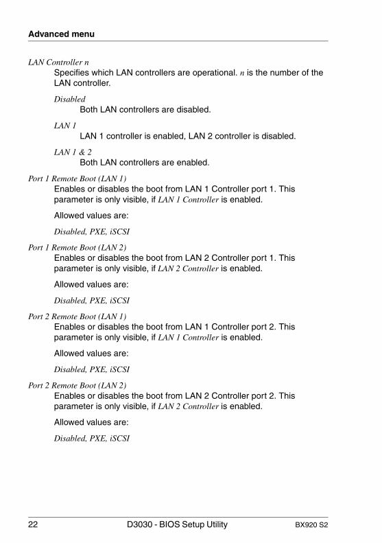
LAN Controller n Specifies which LAN controllers are operational. n is the number of the LAN controller.
DisabledBoth LAN controllers are disabled.
LAN 1LAN 1 controller is enabled, LAN 2 controller is disabled.
LAN 1 & 2Both LAN controllers are enabled.
Port 1 Remote Boot (LAN 1) Enables or disables the boot from LAN 1 Controller port 1. This parameter is only visible, if LAN 1 Controller is enabled.
Allowed values are:
Disabled, PXE, iSCSI
Port 1 Remote Boot (LAN 2) Enables or disables the boot from LAN 2 Controller port 1. This parameter is only visible, if LAN 2 Controller is enabled.
Allowed values are:
Disabled, PXE, iSCSI
Port 2 Remote Boot (LAN 1) Enables or disables the boot from LAN 1 Controller port 2. This parameter is only visible, if LAN 1 Controller is enabled.
Allowed values are:
Disabled, PXE, iSCSI
Port 2 Remote Boot (LAN 2) Enables or disables the boot from LAN 2 Controller port 2. This parameter is only visible, if LAN 2 Controller is enabled.
Allowed values are:
Disabled, PXE, iSCSI

BX920 S2 D3030 - BIOS Setup Utility 23
Advanced menu
Mezz. Card 1: Type Indicates the mezzanine card type installed in mezzanine card slot 1.
EmptyNo mezzanine card is installed.
LAN LAN mezzanine card is installed.
Fibre ChannelFibre channel mezzanine card is installed.
iSCSIiSCSI mezzanine card is installed.
CNACNA mezzanine card is installed.
SAS RAIDSAS RAID mezzanine card is installed.
OthersAnother type of mezzanine card is installed.
Port n Remote Boot Specifies whether OPROM of port n is active during POST or not. This parameter is only visible, if a LAN mezzanine card is installed.
DisabledOPROM is not activated for port n.
PXE The PXE-BIOS is activated and enables the operating system to be loaded from a server via a local network connection with PXE.
iSCSI The iSCSI LAN-BIOS is activated and enables the operating system to be loaded from a server via a local network connection with iSCSI.
Remote Boot Specifies whether OPROM is active during POST or not. This parameter is only visible, if a fibre channel, iSCSI or another mezzanine card is installed.
Allowed values are:Enabled, Disabled

24 D3030 - BIOS Setup Utility BX920 S2
Advanced menu
Mezz. Card 2: Type Indicates the mezzanine card type installed in mezzanine card slot 2.
EmptyNo mezzanine card is installed.
LAN LAN mezzanine card is installed.
Fibre ChannelFibre channel mezzanine card is installed.
iSCSIiSCSI mezzanine card is installed.
CNACNA mezzanine card is installed.
SAS RAIDSAS RAID mezzanine card is installed.
OthersAnother type of mezzanine card is installed.
Port n Remote Boot Specifies whether OPROM of port n is active during POST or not. This parameter is only visible, if a LAN mezzanine card is installed and if no LAN mezzanine card is installed in mezzanine card slot 1.
DisabledOPROM is not activated for port n.
PXE The PXE-BIOS is activated and enables the operating system to be loaded from a server via a local network connection with PXE.
iSCSI The iSCSI LAN-BIOS is activated and enables the operating system to be loaded from a server via a local network connection with iSCSI.
Remote Boot Specifies whether OPROM is active during POST or not. This parameter is only visible, if a fibre channel, iSCSI or another mezzanine card is installed.
Allowed values are:Enabled, Disabled

BX920 S2 D3030 - BIOS Setup Utility 25
Advanced menu
5.2 Advanced System Configuration
The following parameters can be set in this menu. Some of them are only available under special preconditions.
High Precision Event Timer Provided that it is enabled, the operating system is able to make use of the High Precision Event Timer, which allows it to meet the requirements of time-critical applications.The advanced timer is also known as the Multimedia Timer.
Disabled High Precision Event Timer is disabled.
Enabled High Precision Event Timer is enabled.
I/OAT Used to support I/OAT (Intel® I/O Acceleration Technology) for a network controller. Additional hardware capabilities will improve the application performance and application response time. Requires also support from the drivers and the operating system.
DisabledA network controller cannot utilize the additional hardware capabilities.
Enabled A network controller can utilize the additional hardware capabilities.
PCIe SR-IOV Single Root I/O Virtualization (SR-IOV)allows multiple operating systems (virtual machines) to natively share PCI Express devices simultaneously. Multiple virtual PCI Express functions will be derived from a single physical PCI Express function, which leads to an increased demand of address space.
Disabled The operating system cannot make use of the SR-IOV technology. No virtual PCI Express functions will be created.

26 D3030 - BIOS Setup Utility BX920 S2
Advanced menu
Enabled An SR-IOV capable operating system can make use of the SR-IOV technology to increase the I/O performance. Virtual PCI Express functions will be created in an enlarged PCI Express address space.
5.3 Advanced Memory Options
The following parameters can be set in this menu. Some of them are only available under special preconditions.
Memory Scrubbing Specifies whether the full memory will periodically be screened in the background. Correctable memory error will be detected and corrected before an accumulation of such errors may lead to an uncorrectable memory error.
DisabledNo background memory screening will be performed, resulting in increased performance.
Enabled Background memory screening will be performed, resulting in increased reliability.
V CAUTION!
The cause of correctable memory errors may be inappropriate environmental conditions, e.g. high temperature.
Memory Redundancy Memory capacity can be reserved for possible error treatment.
For detailed instructions refer to the corresponding technical manual of the system board.
DisabledDeactivates this function.
Sparing The BIOS uses a memory bank as a reserve for the case that too many correctable errors occur in another memory bank. Before some uncorrectable error occurs, the content of this memory bank is routed back into the sparing bank. The potentially defective

BX920 S2 D3030 - BIOS Setup Utility 27
Advanced menu
memory bank is not used anymore. This procedure is executed while working. At the same time, the memory error is reported to the administrator.
Mirroring The BIOS divides the system memory in half and retains two copies of all data in the memory. It prevents a system crash when uncorrectable errors occur. In seldom cases in which uncorrectable errors occur, data cannot be collected from the first copy, the data is immediately called from the second copy. At the same time, the memory error is reported to the administrator.
Memory Power Mode The memory modules may operate at different speeds (frequencies). The performance will increase at higher speeds, whereas energy saving will be increased at lower speeds. The possible memory speeds are depending on the populated memory module configuration.
EnergyThe lowest possible memory speed is used to save energy.
PerformanceThe highest possible memory speed is used, for best performance.
NUMA Optimization NUMA (Non-Uniform Memory Access) is a memory architecture for multiprocessor systems. Each processor has its own local memory, but it may also access the local memory of the other processors (shared memory). The access to the local memory is faster than to the shared memory.
DisabledThe full system memory is divided into many small areas of interleaved local and shared memory.
Should be selected if the operating system does not support NUMA.
EnabledThe full system memory is divided into areas of non-interleaved local and shared memory. Best performance with a NUMA aware ACPI operating system.

28 D3030 - BIOS Setup Utility BX920 S2
Advanced menu
5.4 Advanced Processor Options
The following parameters can be set in this submenu. Some of them are only available under special preconditions.
CPU Mismatch Detection Checking of the processor data (processor type and speed) can be enabled or disabled. The check ascertains whether the processor data has changed between two system starts. In multiprocessor systems a check is also made to ascertain whether the processor data of all processors are identical.
An error message is displayed if the processor data differs.
Disabled CPU Mismatch Detection is disabled.
Enabled CPU Mismatch Detection is enabled.
QPI Bus Speed QPI bus links provide the connection between the CPU(s) and the chip set. In multi socket systems, they also connect the CPUs among each other. Depending on the CPU(s) and the chipset, QPI bus links can be run at different speeds. This parameter controls the speed of the QPI bus links in your system.
Automatic BIOS will find out the maximum speed depending on the CPU(s) and chipset present in your system.
Other options (CPU dependent)
Possible speed settings vary with CPU(s) and chipset so different values are displayed depending on your system. Choose one of the values to explicitly set the speed the QPI bus links will be run at.
Core Multi-Processing For processors that contain several logical processors, all but one logical processors can be deactivated.
Disabled All but one logical processors are deactivated.

BX920 S2 D3030 - BIOS Setup Utility 29
Advanced menu
Enabled All available logical processors are active.
Enhanced SpeedStep Defines the processor voltage and frequency. EIST (Enhanced Intel SpeedStep® Technology) is an energy saving function.
I The processor voltage is adapted to the respective system requirements. A reduction in the clock frequency causes less power to be required by the system.
Disabled Enhanced SpeedStep functionality is disabled.
Enabled Enhanced SpeedStep functionality is enabled.
Enhanced Idle Power State If supported by the operating system, the CPU is stopped if possible to save energy.
Disabled Enhanced Idle Power State functionality is disabled.
Enabled Enhanced Idle Power State functionality is enabled.
Virtualization Technology (VT-x) Supports the virtualization of platform hardware and several software environments, based on VMX (Virtual Machine Extensions) to support the use of several software environments using virtual computers. Virtualization technology extends the processor support for virtualization purposes with the 16 Bit and 32 Bit protected modes and with the EM64T (Intel® Extended Memory 64 Technology) mode.
Disabled A VMM (Virtual Machine Monitor) cannot use the additional hardware features.
Enabled A VMM can use the additional hardware features.
Virtualization Technology (VT-d) VT-d provides hardware support for sharing I/O devices between multiple virtual machines. VMMs (Virtual Machine Monitors) can use VT-d for managing multiple virtual machines accessing the same physical I/O device.

30 D3030 - BIOS Setup Utility BX920 S2
Advanced menu
Disabled VT-d is disabled and not available for VMMs.
Enabled VT-d is enabled.
NX Memory Protection Defines the protection for executable memory areas (anti-virus protection). The function is only effective if it is also supported by the operating system.
Enabled Enables the operating system to switch on the function Execute Disable.
Disabled Prevents the operating system from being able to switch on the function Execute Disable.
Adjacent Cache Line Prefetch Available if the processor offers a mechanism for loading an additional adjacent 64 Byte cache line during every cache request of the processor.
I With this parameter you can change the performance settings for non-standard applications. It is recommended that you should adhere to the default settings for standard applications.
Enabled The processor loads the requested cache line and the adjacent cache line.
Disabled The processor loads the requested cache line.
Hardware Prefetch Enables a prefetch to the hardware.
I With this parameter you can change the performance settings for non-standard applications. It is recommended that you should adhere to the default settings for standard applications.
Enabled Activates the hardware prefetcher of the CPU.
Disabled Deactivates the hardware prefetcher of the CPU.

BX920 S2 D3030 - BIOS Setup Utility 31
Advanced menu
DCU Streamer Prefetch If activated data content, that is likely required, is preloaded automatically to the L1 cache when the memory bus is inactive. Fetching content form cache instead of memory reduces the latency especially for applications with linear data access.
I With this parameter you can change the performance settings for non-standard applications. It is recommended that you should adhere to the default settings for standard applications.
EnabledActivates the DCU Streamer Prefetch of the CPU.
DisabledDeactivates the DCU Streamer Prefetch of the CPU.
DCU IP Prefetch Performance gains are expected when code is organized sequentially and in contiguous memory.
I With this parameter you can change the performance settings for non-standard applications. It is recommended that you should adhere to the default settings for standard applications.
EnabledActivates the DCU IP Prefetch of the CPU.
DisabledDeactivates the DCU IP Prefetch of the CPU.
Data Reuse Optimization Reduces the internal bandwidth, which is consumed by constantly updating the different cache levels.
I With this parameter you can change the performance settings for non-standard applications. It is recommended that you should adhere to the default settings for standard applications.
EnabledActivates the Data Reuse Optimization of the CPU.
DisabledDeactivates the Data Reuse Optimization of the CPU.

32 D3030 - BIOS Setup Utility BX920 S2
Advanced menu
Intel (R) HT Technology Hyper-threading technology allows a single physical processor core to appear as several logical processors. With this technology the operating system can better utilize the internal processor resources, which in turn leads to increased performance. The advantages of this technology can only be used by an operating system which supports ACPI. This setting has no effect on operating systems which do not support ACPI.
Disabled An ACPI operating system can only use the first logical processor of the physical processor. This setting should only be used if hyper-threading technology has not been correctly implemented in the ACPI operating system.
Enabled An ACPI operating system can use all logical processors within a physical processor.
Turbo Boost Technology Allows the processor to run faster than the marked frequency if the OS requests a higher performance state (P0).
Disabled Turbo Boost Technology is disabled.
Enabled Turbo Boost Technology is enabled.
Performance/Power SettingWhen the Parameter Turbo Boost Technology is Enabled, it can operate in 2 different modes.
TraditionalThe Turbo Boost Technology engages as soon as the maximum processor performance state (P0) is sustained, thus providing the maximum performance.
OptimizedThe Turbo Boost Technology only engages after the maximum processor performance state (P0) is sustained for more than 2 seconds, thus consuming less power.

BX920 S2 D3030 - BIOS Setup Utility 33
Advanced menu
Limit CPUID Functions Defines the number of CPUID functions which can be called by the processor. Some operating systems cannot process new CPUID commands which support more than three functions. This parameter should be enabled for these operating systems.
Disabled All CPUID functions are supported.
Enabled For reasons of compatibility with the operating system, only a reduced number of CPUID functions are supported by the processor.

34 D3030 - BIOS Setup Utility BX920 S2
Advanced menu

BX920 S2 D3030 - BIOS Setup Utility 35
Security menu
6 Security menuThe following parameters can be set in this menu. Some of them are only available under special preconditions.
Figure 6: "Security" menu
The system shuts down after three times password attempts. If this happens, turn off the server, turn it back on, and then enter the correct password.
If you forgot your password and cannot start the server, change the jumper setting on the system board to reset the password. For jumper settings, refer to the corresponding technical manual for the system board.
Supervisor Password Indicates the current status of the supervisor password.
Not Installed No supervisor password is assigned.
Installed A supervisor password is assigned.

36 D3030 - BIOS Setup Utility BX920 S2
Security menu
User Password Indicates the current status of the user password.
Not Installed No user password is assigned.
Installed A user password is assigned.
Set Supervisor Password When you press the [Enter] key, a window opens where you can define the supervisor password. Enter a character string to define a password. If you confirm an empty password field, the password will be deleted.
I To call up the complete BIOS setup, you need the supervisor password. The user password allows only a very limited access to the BIOS setup.
Set User Password For assigning the user password, a supervisor password must already be assigned. The user password prevents unauthorized access to your system.
When you press the [Enter] key, a window opens where you can assign the user password.Enter a character string to define a password. If you confirm an empty password field, the password will be deleted.
If you call up the BIOS setup with the user password, you cannot change most menu options.
Supervisor Password Lock If a supervisor password is defined this field establishes the effect of the password.
Standard The supervisor password prevents unauthorized opening of the BIOS setup utility.
Extended The supervisor password prevents unauthorized opening of the BIOS setup utility and locks the keyboard during the system initialization phase. This prevents unauthorized access to settings for installed expansion cards with an own BIOS.

BX920 S2 D3030 - BIOS Setup Utility 37
Security menu
Password On Boot Enables or disables password entry on boot.
Allowed values are:Enabled, Disabled
Flash Write Assigns write protection to the system BIOS.
Disabled The system BIOS cannot be written. Flash-BIOS update is not possible.
Enabled The system BIOS can be written if the appropriate switch option (see manual for the system board) is set accordingly. Flash BIOS update is possible.
TPM (Security Chip) Settings Opens the submenu used to activate TPM (Trusted Platform Module) and adjust TPM settings (see "TPM (Trusted Platform Module) Settings" on page 37).
If this setup menu is available, then the system board includes a security and encryption chip (TPM) that complies with TCG (Trusted Computing Group) Specification 1.2. The menu is not displayed on systems without a TPM.
Similarly to a SmartCard, this chip allows security-relevant data (passwords etc.) to be stored securely.
6.1 TPM (Trusted Platform Module) Settings
The TPM is available as a secure memory for secret keys. For example, data can be generated, which can only be read or run on this system. Security protocols such as SSL (Secure Socket Layer) for Internet connections, IPSec (LAN encryption), S-MIME (e-mail encryption), WLAN encryption, etc. can also be supported.
The following parameters can be set in this menu. Some of them are only available under special preconditions.

38 D3030 - BIOS Setup Utility BX920 S2
Security menu
Security Chip Activates/deactivates support for the TPM (Trusted Platform Module). This parameter enables or disables the TPM on the hardware level. If the TPM is disabled, it behaves as if it was not there and is neither detectable nor does it react to any command.
Disabled TPM support is deactivated.
Enabled TPM support is activated.
Current TPM State Indicates the current state of the TPM.
The state can take the following values:
Disabled and Activated Disabled and Deactivated Enabled and Activated Enabled and Deactivated
I If the TPM is disabled by the Security Chip parameter (see above), the TPM state will always be Disabled and Deactivated.
Change TPM State Changes the state of the TPM (Security Chip).
After changing the TPM state the system will perform the following steps:
– System Reset– The system automatically displays the TPM Physical Presence
Operations setup page (see below).– System Reset– According to the user's selection in the TPM Physical Presence
Operations setup page, the change of the TPM state is either executed or discarded.
No Change Leaves current security chip state unchanged.
Enable & Activate Enables and activates the security chip for use by application.
Disable & Deactivate Disables and deactivates the security chip.

BX920 S2 D3030 - BIOS Setup Utility 39
Security menu
V CAUTION!
Deactivating the TPM may affect other security applications.
Clear Clears all user generated keys stored in the security chip.
V CAUTION!
If Clear is selected all user generated keys stored in the security chip will be deleted. Accessing of encrypted data may not be possible furthermore.

40 D3030 - BIOS Setup Utility BX920 S2
Security menu

BX920 S2 D3030 - BIOS Setup Utility 41
7 Power menuThe following parameters can be set in this menu. Some of them are only available under special preconditions.
Figure 7: "Power" menu
Power-on Source Specifies whether the switch on sources for the system are managed by the BIOS or the ACPI operating system.
BIOS Controlled The switch on sources are managed by the BIOS.
ACPI Controlled The switch on sources are managed by the ACPI operating system.

42 D3030 - BIOS Setup Utility BX920 S2
Power menu
Power-on Source: LAN Determines whether the system can be switched on via a LAN controller (on the system board or expansion card).
Disabled The system cannot be switched on via a LAN controller.
Enabled The system can be switched on via a LAN controller.
Power Failure Recovery Specifies the system restart behavior after a power failure.
Always Off The system performs a status check and then switches off.
Always On The system performs a status check and then switches on.
For the UPS scheduled operation, set it to Always On. Otherwise, the server may not be turned on at the set time.
Previous State The system performs a status check and then returns the mode it was in before the power failure occurred (On or Off).
I All wake up sources are reconfigured during the short initialization process. The system can be woken up via LAN etc. When Disabled is set, the system can only be woken up using the power-on button.

BX920 S2 D3030 - BIOS Setup Utility 43
8 Server menuThe following parameters can be set in this menu. Some of them are only available under special preconditions.
Figure 8: "Server" menu
O/S Boot Timeout Specifies whether the system is restarted if the server management process (ServerView Agent) is unable to establish a connection with the iRMC. After a successful operating system start-up the ServerView Agent starts the communication with the iRMC within a specified period. The iRMC assumes a start-up error if a timeout occurs and may restart the system to recover from this error.
Disabled The iRMC does not restart the system on O/S Boot Timeout. This selection must be used if ServerView is not installed to avoid inadvertently system restarts by the iRMC.

44 D3030 - BIOS Setup Utility BX920 S2
Server menu
Enabled The iRMC restarts the system on O/S Boot Timeout, because it assumes an operating system start-up error.
I – If Enabled is set, the server may not operate as intended. For example, the server may automatically turn off or restart without any commands.
– When starting up the system by using ServerView Suite DVD 1, be sure to disable the O/S Boot Timeout, even when ServerView Agent has been installed on the system. If the system starts up with this parameter enabled, the server may not operate as intended. For example, the server may automatically turn off or restart without any commands.
– When setting this function, refer to ServerView Suite manuals.
Action Determines the action taken after the boot watchdog expires.
Continue The system continues to run.
Reset The system is restarted by a system reset.
Power Cycle The system is restarted by a power cycle.
Timeout Value Specifies the time after which the system is rebooted if enabled via O/S Boot Timeout. Allowed values are 0...100
0 Time monitoring is disabled.
1...100 The system is rebooted after the selected time (in minutes) has expired.
Pressing the [+] key or the [- ] key increases or decreases this value.
ASR&R Boot Delay Specifies the system reboot delay after the system shuts down as a result of an error (e.g. excessively high temperature). The system is rebooted after the set wait time has expired.

BX920 S2 D3030 - BIOS Setup Utility 45
Server menu
Allowed values are: 1 min. to 30 min.
Pressing the [+] key or the [- ] key increases or decreases this value.
Power Cycle Delay Specifies the minimum time that must be expired before the system can be switched on again after it has been switched off.
Allowed values are: 0 sec. to 15 sec.
Pressing the [+] key or the {-} key increases or decreases this value.
Temperature Monitoring Specifies whether the system is disabled if the ambient temperature or the temperature of a processor exceeds the critical value. This protects against damage to the system or data. If the operating system has an active server management process, it takes over the temperature monitoring function and shuts the system down if the temperature values reach a critical level.
Depending on the Boot Retry Counter, the system is enabled again after the time set under ASR&R Boot Delay has expired. The system should have cooled down again during this period.
Disabled The system does not switch off itself if the temperature exceeds the critical value.
Enabled The system switches off itself if the temperature exceeds the critical value.
Boot Retry Counter Specifies the maximum number of attempts to boot the operating system. Each failed attempt is followed by a system reboot after the time set in O/S Boot Timeout has expired. Other critical system errors also result in a system reboot and a counter decrement. After the last attempt, the system is ultimately disabled.
Allowed values are:
0 to 7 number of possible retries
CPU Status Calls a submenu used to make settings for the CPU status (see "CPU Status" on page 46).

46 D3030 - BIOS Setup Utility BX920 S2
Server menu
Memory Status Calls a submenu used to make settings for the memory status (see "Memory Status" on page 47).
PCI Status Calls a submenu used to make settings for the PCI status (see "PCI Status" on page 47).
Console Redirection Calls a submenu used to make settings for the terminal communication (see "Console Redirection (CR)" on page 48).
IPMI Calls a submenu used to make settings for the Intelligent Platform Management Interface (see "IPMI" on page 49).
8.1 CPU Status
The following parameters can be set in this menu. Some of them are only available under special preconditions.
CPU x Status Specifies whether the processor can or cannot be used. Only disable a processor if it has reported an internal malfunction. The malfunction is recorded in the error log, which you can view using the Management Blade Web interface, the ServerView Operations Manager or the iRMC S2's Web interface.
Failed The operating system cannot use the processor. It was disabled automatically by the system after an internal malfunction.
Disabled The operating system cannot use the processor. It was manually disabled.
Enabled The operating system can use the processor.
Empty There is no processor populated.

BX920 S2 D3030 - BIOS Setup Utility 47
Server menu
8.2 Memory Status
In this submenu the memory modules can be marked as faulty. Faulty memory modules are no longer used when the system is rebooted if at least one error-free bank is available. The memory capacity is reduced accordingly.
DIMM-xx Displays the current status of the memory modules.
Failed The system does not use the memory module. It was disabled automatically by the system after a memory error. If you have replaced a defective memory module, you must set the parameter to Enabled again.
Disabled The system does not use the memory module. It was manually disabled.
Enabled The system uses the memory module.
Empty There is no memory module populated.
8.3 PCI Status
This submenu shows the current status of the expansion card in the slots.
Slot x Displays the current status of the expansion card in this slot.
Failed An error was detected for this slot. The expansion card in this slot may have a problem.
Enabled No errors were reported for this slot. The expansion card in this slot can be used without restriction.
Empty There is no expansion card in this slot.

48 D3030 - BIOS Setup Utility BX920 S2
Server menu
8.4 Console Redirection (CR)
The following parameters can be set in this menu. Some of them are only available under special preconditions.
Port Specifies the interface used for communication with the terminal.
Disabled The terminal interface is disabled.
Serial 1 The terminal uses the serial interface on the I/O Riser.
Baud Rate Specifies the transfer rate for communication with the terminal. This setting must be identical on both terminal and server.
Allowed values are: 9600, 19.2 k, 38.4 K, 57.6 K, 115.2 K
The data is transferred to the terminal at the rate set.
Protocol Shows the assigned console type. This setting must be identical on both terminal and server.
Allowed values are: VT 100, ANSI
The assigned console is used to transfer the data to the terminal.
Flow Control This setting determines how the transfer via the interface is controlled. This setting must be identical on both terminal and server.
None The interface is operated without transfer control.
XON/XOFF The transfer control is performed by the hardware. This mode must also be supported by the cable.
Continue C.R. after POST Specifies whether or not the Console Redirection function is executed after the BIOS POST (Power-On-Self-Test).
Off The Console Redirection does not continue to run after the POST.
On The Console Redirection continues to run after the POST.

BX920 S2 D3030 - BIOS Setup Utility 49
Server menu
8.5 IPMI
The following parameters can be set in this menu. Some of them are only available under special preconditions.
SM Error Halt Configures the system behavior during the self-test if a system monitoring error is reported by the iRMC (e. g. fan monitoring, temperature monitoring). This setting is only effective if the POST Errors parameter has been enabled in the Boot Features menu.
Disabled The system start-up is not stopped when the iRMC reports an error to the BIOS. The error is only displayed.
Enabled If the iRMC reports an error to the BIOS, the system start-up is stopped after the self-test.
Load iRMC Default Values Specifies whether the iRMC default values are loaded or not.
No No action is taken.
Yes The iRMC default values are loaded when you choose Save Changes & Exit to exit the BIOS setup. Any BIOS setup settings that affect the iRMC are not lost by this setting. They are sent to the iRMC after the iRMC default values are loaded and therefore overwrite the corresponding values again.
The setting is automatically set to No after the default values are loaded.
Event Log Full Mode Specifies whether or not the System Event Log can be overwritten.
Overwrite If the System Event Log is full, additional events overwrite the oldest entries in the System Event Log. In this case, newer events are more important than older events.

50 D3030 - BIOS Setup Utility BX920 S2
Server menu
Maintain If the System Event Log is full, no further events are entered. The System Event Log file must be cleared first before additional events can be entered. In this case, older events are more important than newer events.
SDRR Version Shows the SDRR version number.
LAN Settings Calls a submenu, where you can make the following LAN settings for iRMC (see "LAN Settings" on page 50).
IPMI Status Opens a window in which the current IPMI state is displayed (see "IPMI Status" on page 52).
8.5.1 LAN Settings
Management LAN Enables the LAN interface, which can be used by the iRMC.
Disabled The iRMC LAN interface is disabled.
Enabled The iRMC LAN interface is enabled.
Management LAN Port Specifies which LAN interface can be used by the iRMC.
Management The iRMC uses the selected Management LAN interface for communication.
LAN1/LAN2 The iRMC uses the system LAN interface for communication.
DHCP Specifies whether DHCP (Dynamic Host Configuration Protocol) support for the iRMC is enabled or disabled. An IP address can automatically be assigned to iRMC from a DHCP server in the network via the DHCP network protocol.
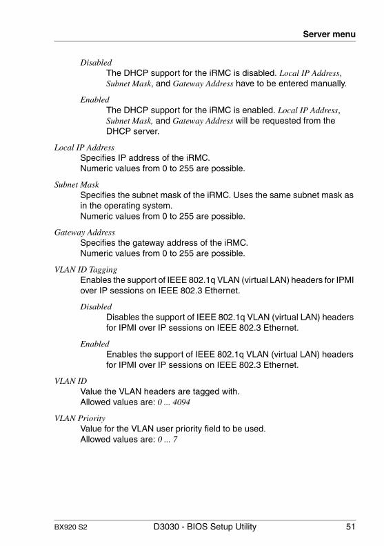
BX920 S2 D3030 - BIOS Setup Utility 51
Server menu
Disabled The DHCP support for the iRMC is disabled. Local IP Address, Subnet Mask, and Gateway Address have to be entered manually.
Enabled The DHCP support for the iRMC is enabled. Local IP Address, Subnet Mask, and Gateway Address will be requested from the DHCP server.
Local IP Address Specifies IP address of the iRMC.Numeric values from 0 to 255 are possible.
Subnet Mask Specifies the subnet mask of the iRMC. Uses the same subnet mask as in the operating system.Numeric values from 0 to 255 are possible.
Gateway Address Specifies the gateway address of the iRMC.Numeric values from 0 to 255 are possible.
VLAN ID Tagging Enables the support of IEEE 802.1q VLAN (virtual LAN) headers for IPMI over IP sessions on IEEE 802.3 Ethernet.
Disabled Disables the support of IEEE 802.1q VLAN (virtual LAN) headers for IPMI over IP sessions on IEEE 802.3 Ethernet.
Enabled Enables the support of IEEE 802.1q VLAN (virtual LAN) headers for IPMI over IP sessions on IEEE 802.3 Ethernet.
VLAN ID Value the VLAN headers are tagged with.Allowed values are: 0 ... 4094
VLAN Priority Value for the VLAN user priority field to be used.Allowed values are: 0 ... 7
52 D3030 - BIOS Setup Utility BX920 S2
Server menu
8.5.2 IPMI Status
IPMI Specification Version Provides information about the version of the IPMI specification the system implements.
iRMC Hardware Provides technical version information about the iRMC hardware.
iRMC Firmware Version Provides additional version information about the iRMC firmware.

BX920 S2 D3030 - BIOS Setup Utility 53
9 Boot menuThe following parameters can be set in this menu. Some of them are only available under special preconditions.
Figure 9: "Boot" menu
This menu can be used to define the sequence of the drives from which the system is booted.
For references to the operation please see the help area in this menu.
1st Boot Device / 2nd Boot Device / 3rd Boot Device / 4th Boot Device / 5th Boot Device Displays the current boot order.
Ê Press the cursor keys Ê or Ë to select the device for which you want to change the boot order.
Ê Press the [+] key to increase the priority and the [- ] key to decrease the priority for the selected device.

54 D3030 - BIOS Setup Utility BX920 S2
Boot menu

BX920 S2 D3030 - BIOS Setup Utility 55
10 Exit menuThe following parameters can be set in this menu.
Figure 10: "Exit" menu
Save Changes & Exit To save the current menu entries and exit the BIOS setup, select Save Changes & Exit and Yes.The system will be rebooted and the new settings will be effective.
Discard Changes & Exit To discard the changes you have made, select Discard Changes & Exit and Yes.The settings that were in use when the BIOS setup was opened will remain effective. BIOS setup will be closed and the system rebooted.
I On some systems a reset is initiated.

56 D3030 - BIOS Setup Utility BX920 S2
Exit menu
Get Default Values To reset all BIOS setup menus to use default values, select Get Default Values and Yes.
To exit the BIOS setup with these settings, select Save Changes & Exit and Yes.
Load Previous Values To load the values for all menus that were active when BIOS setup was started, select Load Previous Values and Yes.
To exit the BIOS setup with these settings, select Save Changes & Exit and Yes.

BX920 S2 D3030 - BIOS Setup Utility 57
Index
1st Boot Device 532nd Boot Device 533rd Boot Device 534th Boot Device 535th Boot Device 53
AAction 44Adjacent Cache Line Prefetch 30Advanced Memory Option 20Advanced Memory Options 26Advanced menu 19Advanced Processor Option 20, 28Advanced System Configuration 20,
25ASR&R Boot Delay 44
BBaud Rate 48BIOS setup
exiting 11incorrect settings 11menu overview 7navigating 9open 9
Boot Features 16Boot Menu 17Boot menu
open immediately 9Boot Options menu 53Boot Retry Counter 45
CChange TPM State 38Console Redirection 46, 48Continue C.R. after POST 48Core Multi-Processing 28CPU Mismatch Detection 28CPU Status 45, 46CPU x Status 46
Current TPM State 38
DData Reuse Optimization 31DCU IP Prefetch 31DCU Streamer Prefetch 31DHCP 50DIMM Status 47Discard Changes & Exit 55
EEnhanced Idle Power State 29Enhanced SpeedStep 29Event Log Full Mode 49Exit menu 55Extended Memory 16
FFast Boot 17Flash Write 37Flow Control 48
GGateway Address 51Get Default Values 56
HHardware Prefetch 30High Precision Event Timer 25Hyper-Threading 32
II/OAT 25IO-Blade Option ROM Scan 21IPMI 46, 49IPMI Status 50
LLAN 1 Controller
Port 1 Remote Boot 22Port 2 Remote Boot 22

58 D3030 - BIOS Setup Utility BX920 S2
Index
LAN 2 ControllerPort 1 Remote Boot 22Port 2 Remote Boot 22
LAN Controller 22LAN Settings 50Limit CPUID Functions 33Load iRMC default Values 49Load Previous Values 56Local IP Address 51
MMain menu 15Management LAN 50Management LAN Port 50Memory Power Speed 27Memory Redundancy 26Memory Scrubbing 26Memory Status 46, 47Mezz. Card 1
Type 23Mezz. Card 2
Type 24
NNUMA Optimisation 27NumLock 16NX Memory Protection 30
OO/S Boot Timeout 43
PPassword On Boot 37PCI Status 46, 47PCIe SR-IOV 25Performance/Power Setting 32Peripheral Configuration 20Port 48Port n Remote Boot 23, 24POST Diagnostic Screen 17POST Errors 16Power Cycle Delay 45Power Failure Recovery 42Power menu 41
Power-on Source 41LAN 42
Protocol 48
QQPI Link Speed 28
RRemote Boot 23, 24Reset Configuration Data 19
SSave Changes & Exit 55screen design 10Security Chip 37, 38Security menu 35Serial 20Serial Port1 Address 21Server menu 43Set Supervisor Password 36Set User Password 36Slot x 47SM Error Halt 49Subnet Mask 51Supervisor Password 35Supervisor Password Lock 36Sync RTC with Mgmt. Blade 16System Date 15System Memory 16System Time 15
TTemperature Monitoring 45Timeout Value 44TPM Settings 37Turbo Boost Technology 32
UUSB Devices 21USB Front 21USB Host Controller 21USB Speed 21User Password 36

BX920 S2 D3030 - BIOS Setup Utility 59
Index
VVirtualization Technology (VT-d) 29Virtualization Technology (VT-x) 29VLAN ID 51VLAN ID Tagging 51VLAN Priority 51

60 D3030 - BIOS Setup Utility BX920 S2
Index