pe lecture 1
TRANSCRIPT

7/23/2019 PE Lecture 1
http://slidepdf.com/reader/full/pe-lecture-1 1/31
Power ElectronicsWinter 2012
Lecture 1
Dr. Walid Atef Omran

7/23/2019 PE Lecture 1
http://slidepdf.com/reader/full/pe-lecture-1 2/31
About me
Current: Assistant professor at Ain-Shams University
Part time lecturer at the GUC
Past:
Planning engineer at the Independent Electricity System Operator –
Canada
International TA developer at the University of Waterloo – Canada
Education
PhD title: “Performance Analysis of Grid Connected Photovoltaic
Systems” from the University of Waterloo – Canada
2

7/23/2019 PE Lecture 1
http://slidepdf.com/reader/full/pe-lecture-1 3/31
Contact Information
Dr. Walid Atef Omran
GUC email: [email protected]
Personal email: [email protected]
Office: C3 – 214
Office hours: Wednesdays (you have to book an appointment)
3

7/23/2019 PE Lecture 1
http://slidepdf.com/reader/full/pe-lecture-1 4/31
About You
4

7/23/2019 PE Lecture 1
http://slidepdf.com/reader/full/pe-lecture-1 5/31
About the Course
This course will introduce you to the fundamentals of powerelectronics.
The main focus of this course is to discuss the operational aspects
of different power electronic switches and power electronicconverters.
The course is of great importance in practical life due to the wide
application of power electronics in different engineering areas.
5

7/23/2019 PE Lecture 1
http://slidepdf.com/reader/full/pe-lecture-1 6/31
References
Denis Fewson, Introduction to Power Electronics
Ned Mohan, Power Electronics: A First Course
B.K. Bose, Modern Power Electronics and AC Drives
M.H. Rashid, Power Electronics Handbook
B.M. Bird, K.G. King, D.A. Pedder, An Introduction to Power
Electronics
Cyril W. Lander, Power Electronics 6
7/23/2019 PE Lecture 1
http://slidepdf.com/reader/full/pe-lecture-1 7/31
Course Outline
Part A: Power Electronic Switches and Power losses
Part B: Rectifiers
Part C: Inverters
Part D: DC Choppers
7

7/23/2019 PE Lecture 1
http://slidepdf.com/reader/full/pe-lecture-1 8/31
Course Logistics
Lectures: Wednesdays 1st lecture, H12
Grading Scheme:
8
Final Exam45%
MidtermExam20%
Project5%
Quizzes15%
Assignments15%

7/23/2019 PE Lecture 1
http://slidepdf.com/reader/full/pe-lecture-1 9/31
Recommendations
Attending the lectures and tutorials is a must in this course toavoid facing difficulties in understanding the material.
Taking notes is highly recommended because you will need to
remember what I say in the lecture.
Please be on time because lectures will start on time.
Watch out for Due Dates . Assignments and reports should besubmitted on time.
Please contact me as soon as you face any problem related to the
course. 9
7/23/2019 PE Lecture 1
http://slidepdf.com/reader/full/pe-lecture-1 10/31
Today’s Lecture
I ntroduction
What is Power Electronics
Power electronic converters
Power Electronic Devices
Uncontrolled power electronic Switches
Diodes
Semi-controlled power electronic Switches Thyristors
10

7/23/2019 PE Lecture 1
http://slidepdf.com/reader/full/pe-lecture-1 11/31
Introduction
Power electronics is an established technology that bridges the powerindustry with its need for fast controllers.
The main function of power electronics is to condition the power from
a supply to suit the needs of the load.
Power electronics emerged in the late 1950s when the silicon controlled
rectifier, known as thyristor, was developed.
The thyristor, like other power electronic devices, is used as anelectronic switch that is much faster than the mechanical switch.
The power electronic switch is the building block of power electronic
converters.11

7/23/2019 PE Lecture 1
http://slidepdf.com/reader/full/pe-lecture-1 12/31
Power Electronic Converters
There are 4 main types of power electronic converters: AC to DC converters (Rectifiers)
Changes from fixed AC voltage
to DC voltage with variable
magnitude.
DC to AC converters (Inverters)
Changes from fixed DC voltage
to AC voltage with variable
magnitude and frequency.
12

7/23/2019 PE Lecture 1
http://slidepdf.com/reader/full/pe-lecture-1 13/31
Power Electronic Converters
There are 4 main types of power electronic converters: DC to DC converters (DC choppers)
Changes from fixed DC voltage
to DC voltage with variable
magnitude.
AC to AC converters (AC choppers)
Changes from fixed AC voltage with
to AC voltage with variable
magnitude and frequency.
13

7/23/2019 PE Lecture 1
http://slidepdf.com/reader/full/pe-lecture-1 14/31
14
Power Electronic Devices

7/23/2019 PE Lecture 1
http://slidepdf.com/reader/full/pe-lecture-1 15/31
Power Electronic Devices
Power electronic devices operate as electronic switches and can be categorized into three main categories:
1. Uncontrolled electronic switches that turn on and off based on the
conditions of the circuit (power diodes).
2. Semi-controlled electronic switches that turn on based on the
conditions of the circuit and in the presence of an external signal,
but they turn off based on the conditions of the circuit (thyristors).
These devices can be also turned off by the aid of external circuits
called commutation circuits.
3. Controlled electronic switches that turn on and off based on the
conditions of the circuit and on the external signal (e.g., IGBT,
MOSFET, GTO).15

7/23/2019 PE Lecture 1
http://slidepdf.com/reader/full/pe-lecture-1 16/31
Power Diodes
Symbol and Structure:
A power diode is a p-n junction that is capable of handling highvoltages and currents.
It conducts if the voltage of the anode is higher than the cathode
and is turned off when the current passing from the anode to thecathodes falls to zero and the voltage is reversed.
ON: v AK > 0
OFF: v AK < 0 & i AK = 0 16

7/23/2019 PE Lecture 1
http://slidepdf.com/reader/full/pe-lecture-1 17/31
Power Diodes
Static I-V Characteristics:Under steady state conditions, the diode
has two main states:
1) Reverse blocking state: In this case v AK < 0
The p-n junction is reverse biased.
The diode is in the OFF state.
A very small leakage current will flow.
If the voltage is increased till the value
VRBD, reverse breakdown (avalanche breakdown)
will occur and diode will be damaged.
17
Actual characteristics

7/23/2019 PE Lecture 1
http://slidepdf.com/reader/full/pe-lecture-1 18/31
Power Diodes
Static I-V Characteristics:Under steady state conditions, the diode
has two main states:
2) Forward conducting state: In this case v AK > 0
The p-n junction is forward biased.
The diode is in the ON state.
The current increases exponentially as the
voltage increases.
The forward drop voltage, V Df , that depends
on the type of diode (V Df ≈ 0.2V – 1.5V)
.
18
Actual characteristics

7/23/2019 PE Lecture 1
http://slidepdf.com/reader/full/pe-lecture-1 19/31
Power Diodes
Linearized model:
The diode can be represented by a battery and a resistance during
the ON state and by an open circuit in the OFF state.
19
Linearized characteristics
OFF stateON state

7/23/2019 PE Lecture 1
http://slidepdf.com/reader/full/pe-lecture-1 20/31
Power Diodes
Ideal model:
In the ideal case, the diode is represented as a switch, i.e., it is a
short circuit in the ON state and open circuit in the OFF state.
20
Ideal characteristics
OFF stateON state

7/23/2019 PE Lecture 1
http://slidepdf.com/reader/full/pe-lecture-1 21/31
Thyristors (Silicon controlled
Rectifiers – SCRs)
Symbol and Structure:
The thyristor has the highest power rating and the lowest
frequency of operation among all power electronics devices.
It is a 4 layers, 3 junctions, 3 terminals, current controlled (iG),
latching device (latching: the device requires an external signal toturn on and then the signal can be removed).
ON: v AK > 0 & iG > 0
OFF: v AK < 0 & i AK ≈ 0 (i AK < I H ) 21
7/23/2019 PE Lecture 1
http://slidepdf.com/reader/full/pe-lecture-1 22/31
Thyristors (Silicon controlled
Rectifiers – SCRs)
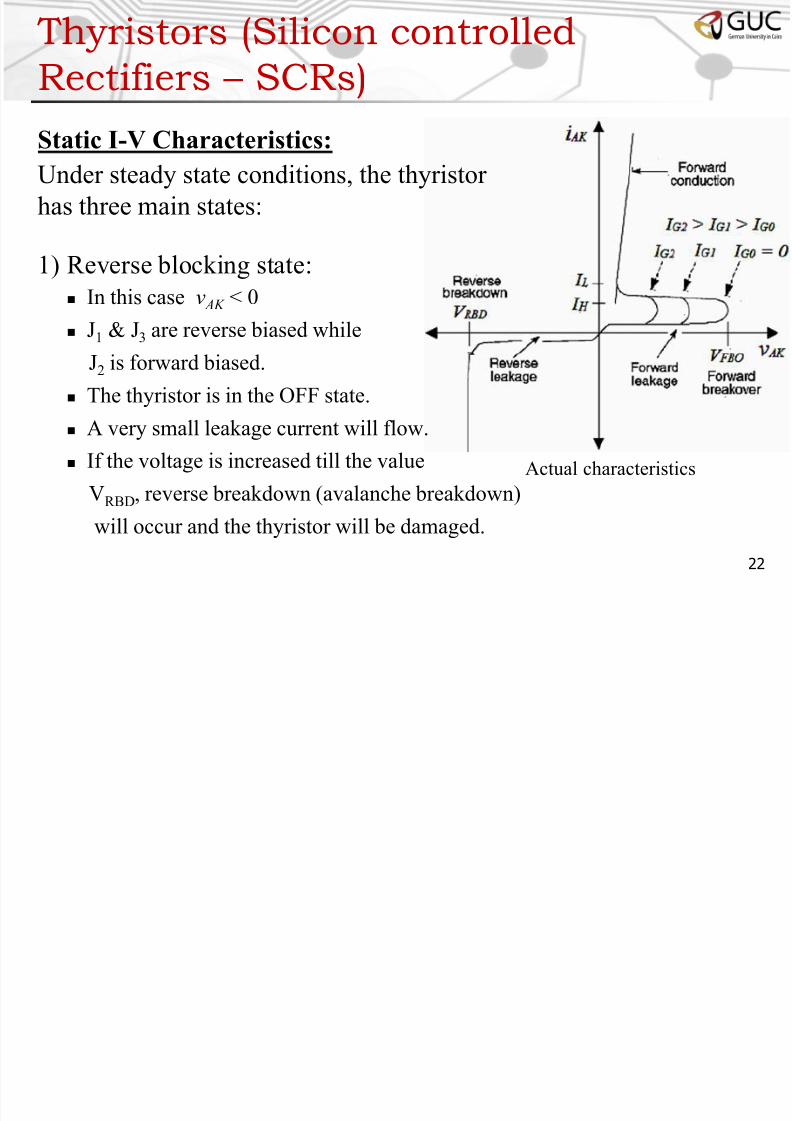
Static I-V Characteristics:Under steady state conditions, the thyristor
has three main states:
1) Reverse blocking state:
In this case v AK < 0
J1 & J3 are reverse biased while
J2 is forward biased.
The thyristor is in the OFF state.
A very small leakage current will flow.
If the voltage is increased till the value
VRBD, reverse breakdown (avalanche breakdown)
will occur and the thyristor will be damaged.
22
Actual characteristics

7/23/2019 PE Lecture 1
http://slidepdf.com/reader/full/pe-lecture-1 23/31
Thyristors (Silicon controlled
Rectifiers – SCRs)
Static I-V Characteristics:Under steady state conditions, the thyristor
has three main states:
2) Forward blocking state:
In this case v AK > 0 & iG = 0
J1 & J3 are forward biased while
J2 is reverse biased.
The thyristor is in the OFF state.
A very small leakage current will flow.
If the voltage is increased till the value
VFBO, forward breakdown will occur and
thyristor will start to conduct without a gate signal. This decreases the
lifetime of the thyristor. 23
Actual characteristics

7/23/2019 PE Lecture 1
http://slidepdf.com/reader/full/pe-lecture-1 24/31
Thyristors (Silicon controlled
Rectifiers – SCRs)
Static I-V Characteristics:Under steady state conditions, the thyristor
has three main states:
3) Forward conducting state:
In this case v AK > 0 & iG > 0
J1, J2 & J3 are forward biased.
The thyristor is in the ON state.
The current increases exponentially as
the voltage increases.
There will be forward drop voltage, V T
(V T ≈ 1.2V – 2.2V)
24
Actual characteristics

7/23/2019 PE Lecture 1
http://slidepdf.com/reader/full/pe-lecture-1 25/31
Thyristors (Silicon controlled
Rectifiers – SCRs)
Important parameters: Latching current ( I L): is the anode current that must be reached for the
thyristor to start conducting before the gate signal is removed (i.e., if
i AK < I L the thyristor will be turned off if the gate signal is removed).
Holding current ( I H ): is the minimum anode current required to keepthe thyristor in the ON state (i.e, if the thyristor is already conducting
and i AK is decreased below I H , then the thyristor will be turned off).
Forward breakover voltage (V FBO
): is the forward voltage at which the
thyristor starts to conduct when there is no gate signal.
Reverse breakdown voltage (V RBD): is the reverse voltage which will
cause the thyristor to conduct in the reverse direction and avalanche
breakdown occurs (thyristor is damaged). 25
h ( l ll d

7/23/2019 PE Lecture 1
http://slidepdf.com/reader/full/pe-lecture-1 26/31
Thyristors (Silicon controlled
Rectifiers – SCRs)
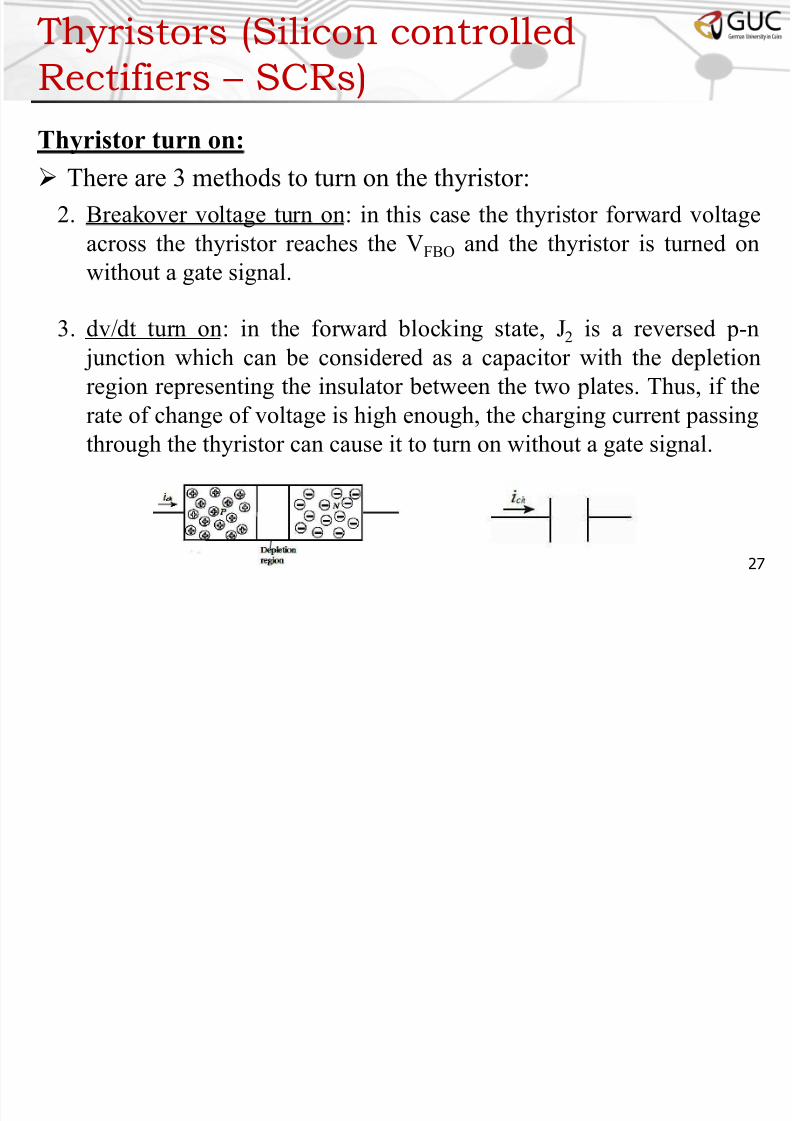
Thyristor turn on: There are 3 methods to turn on the thyristor:
1. Gate turn on: this method requires a current signal at the gate. The
gate signal can be a single short pulse, a train of short pulses or a
single long pulse based on the type of application and load.
26
t
iG
Single short
pulse
Train of short
pulses
Single long
pulse
Shapes of gate pulses
Th i (Sili ll d
7/23/2019 PE Lecture 1
http://slidepdf.com/reader/full/pe-lecture-1 27/31
Thyristors (Silicon controlled
Rectifiers – SCRs)
Thyristor turn on: There are 3 methods to turn on the thyristor:
2. Breakover voltage turn on: in this case the thyristor forward voltage
across the thyristor reaches the VFBO and the thyristor is turned on
without a gate signal.
3. dv/dt turn on: in the forward blocking state, J2 is a reversed p-n
junction which can be considered as a capacitor with the depletion
region representing the insulator between the two plates. Thus, if the
rate of change of voltage is high enough, the charging current passingthrough the thyristor can cause it to turn on without a gate signal.
27
Th i (Sili ll d

7/23/2019 PE Lecture 1
http://slidepdf.com/reader/full/pe-lecture-1 28/31
Thyristors (Silicon controlled
Rectifiers – SCRs)
Thyristor turn off: The thyristor is turned off when i AK is reduced below I H . There
are 2 main methods for turn off:
1. Natural commutation: where the current flowing in the circuit in
which the thyristor is installed decreases naturally below I H (as in thecase of AC circuits).
2. Forced commutation: in cases where the current flowing in the circuit
doesn’t decrease naturally below I H (as in the case of DC circuits),
thus, an auxiliary circuit is used to force the current flowing throughthe thyristor to decrease below I H . This circuit is called the
“commutation circuit”.
28
Th i (Sili ll d

7/23/2019 PE Lecture 1
http://slidepdf.com/reader/full/pe-lecture-1 29/31
Thyristors (Silicon controlled
Rectifiers – SCRs)
Linearized model:
The thyristor can be represented by a battery and a resistance
during the ON state and by an open circuit in the OFF state.
29
Linearized characteristics
OFF stateON state
Th i t (Sili t ll d
7/23/2019 PE Lecture 1
http://slidepdf.com/reader/full/pe-lecture-1 30/31
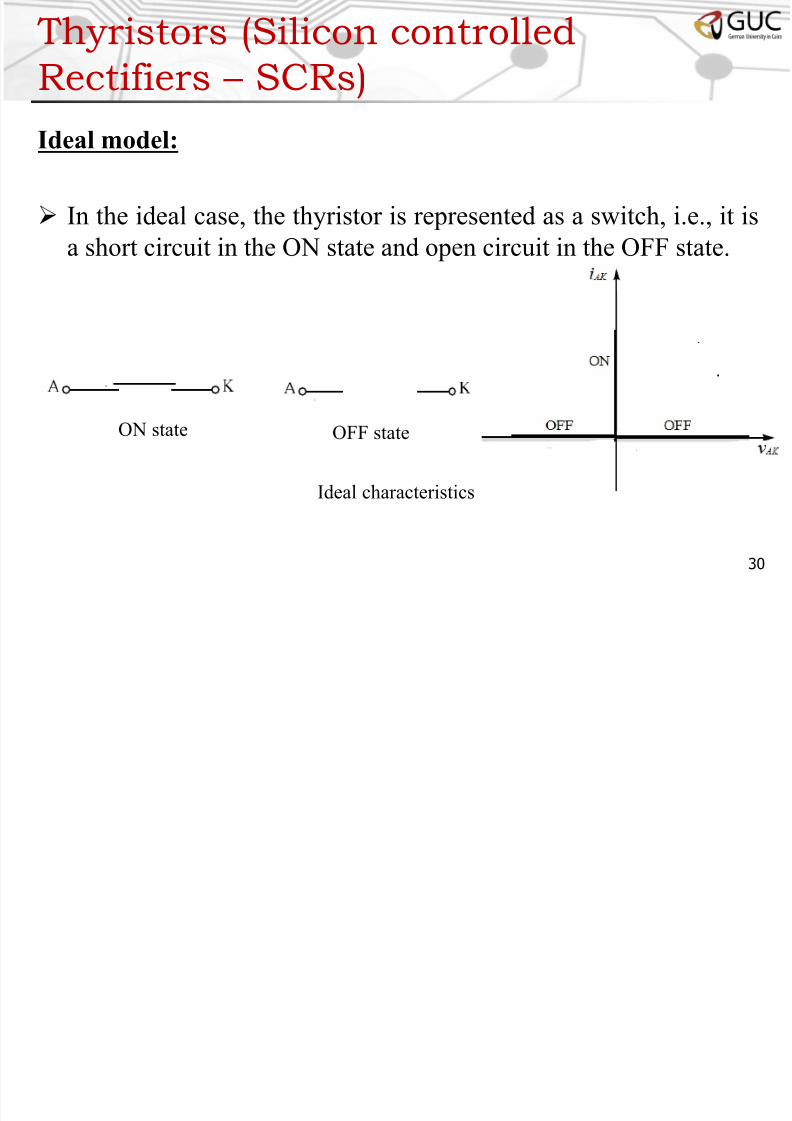
Thyristors (Silicon controlled
Rectifiers – SCRs)
Ideal model:
In the ideal case, the thyristor is represented as a switch, i.e., it is
a short circuit in the ON state and open circuit in the OFF state.
30
Ideal characteristics
OFF stateON state

7/23/2019 PE Lecture 1
http://slidepdf.com/reader/full/pe-lecture-1 31/31
Other Types of Thyristors
The Gate Turn Off Thyristor (GTO) is atype of thyristor that can be turned on by
a current signal in the gate and can be turned
off by applying a reverse current signal at the gate.
The Triac is composed of two thyristors back to back with one
gate. Thus the current can flow in both directions in case of AC
circuits.
31