pellet target tracking at panda - uppsala universitet · pellet target tracking at panda. 1. ......
TRANSCRIPT
(35)
N&P physics seminarIFA 2011-12-01
Hans Calén
Pellet target tracking at PANDA
1
Introduction
• Physics programme• Experimental setup
•Targets
Pellet tracking concept
Prestudies and prototype tests at the Uppsala PTS
Design ideas for PANDA
Status and outlook
(35)
N&P physics seminarIFA 2011-12-01
Hans Calén
2
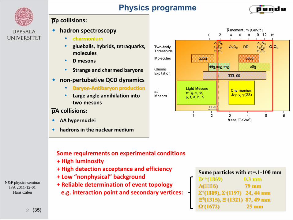
pp collisions:
• hadron spectroscopy• charmonium• glueballs, hybrids, tetraquarks,
molecules• D mesons
• Strange and charmed baryons
• non‐pertubative QCD dynamics• Baryon‐Antibaryon production• Large angle annihilation into
two‐mesons
pA collisions:
• ΛΛ hypernuclei
• hadrons in the nuclear medium
Some requirements on experimental conditions+ High luminosity+ High detection acceptance and efficiency+ Low “nonphysical” background + Reliable determination of event topologye.g. interaction point and secondary vertices:
Some particles with cτ=.1-100 mmD+/-(1869) 0.3 mmΛ(1116) 79 mmΣ+(1189), Σ-(1197) 24, 44 mmΞ0(1315), Ξ-(1321) 87, 49 mmΩ-(1672) 25 mm
Physics programme
(35)
N&P physics seminarIFA 2011-12-01
Hans Calén
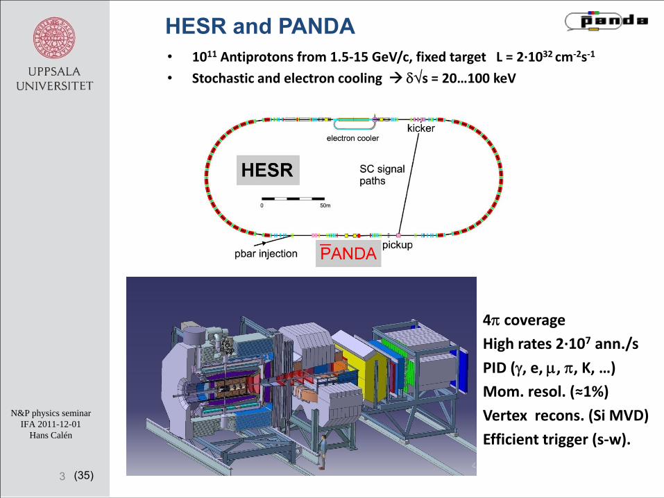
HESR and PANDA
3
• 1011 Antiprotons from 1.5‐15 GeV/c, fixed target L = 2∙1032 cm‐2s‐1
• Stochastic and electron cooling δ√s = 20…100 keV
4π coverageHigh rates 2∙107 ann./s
PID (γ, e, μ, π, K, …)Mom. resol. (≈1%)
Vertex recons. (Si MVD)
Efficient trigger (s‐w).
(35)
N&P physics seminarIFA 2011-12-01
Hans Calén
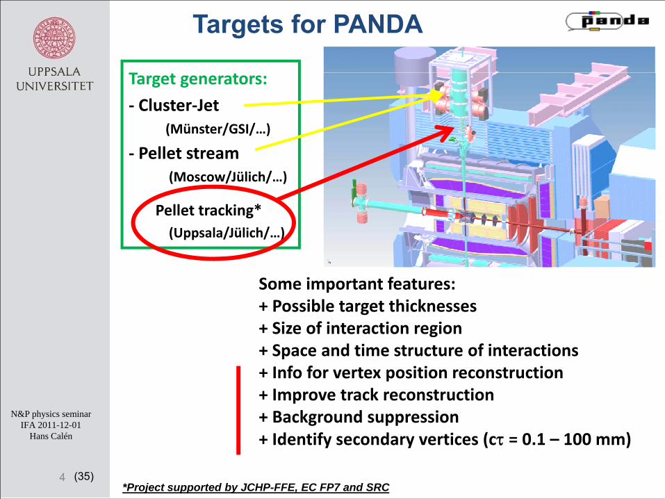
Target generators:
‐ Cluster‐Jet (Münster/GSI/…)
‐ Pellet stream(Moscow/Jülich/…)
Pellet tracking*(Uppsala/Jülich/…)
Targets for PANDA
4*Project supported by JCHP-FFE, EC FP7 and SRC
Some important features:+ Possible target thicknesses+ Size of interaction region + Space and time structure of interactions+ Info for vertex position reconstruction+ Improve track reconstruction+ Background suppression+ Identify secondary vertices (cτ = 0.1 – 100 mm)
(35)
N&P physics seminarIFA 2011-12-01
Hans Calén
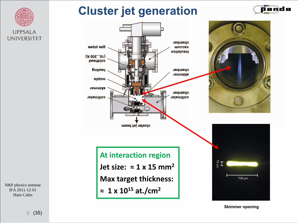
At interaction region
Jet size: ≈ 1 x 15 mm2
Max target thickness:
≈ 1 x 10¹⁵ at./cm2
Cluster jet generation
5Skimmer opening
(35)
N&P physics seminarIFA 2011-12-01
Hans Calén
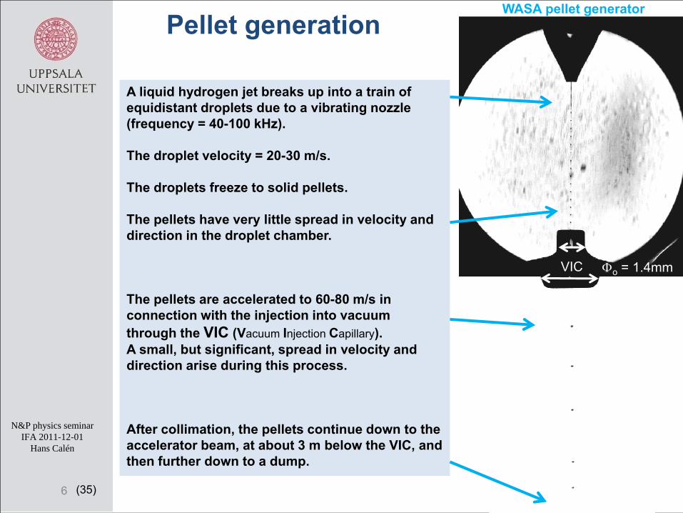
A liquid hydrogen jet breaks up into a train of equidistant droplets due to a vibrating nozzle (frequency = 40-100 kHz).
The droplet velocity = 20-30 m/s.
The droplets freeze to solid pellets.
The pellets have very little spread in velocity and direction in the droplet chamber.
The pellets are accelerated to 60-80 m/s in connection with the injection into vacuum through the VIC (Vacuum Injection Capillary). A small, but significant, spread in velocity and direction arise during this process.
After collimation, the pellets continue down to the accelerator beam, at about 3 m below the VIC, and then further down to a dump.
WASA pellet generator
VIC Φo = 1.4mm
6
Pellet generation
(35)
N&P physics seminarIFA 2011-12-01
Hans Calén
7
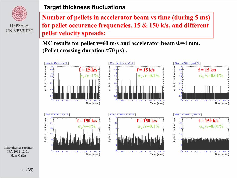
Target thickness fluctuationsNumber of pellets in accelerator beam vs time (during 5 ms) for pellet occurence frequencies, 15 & 150 k/s, and different pellet velocity spreads:MC results for pellet v=60 m/s and accelerator beam Φ=4 mm.(Pellet crossing duration ≈70 μs) .
f = 15 k/sσv /v=1%
f = 15 k/sσv /v=0.1%
f = 150 k/sσv/v=1%
f = 150 k/sσv /v=0.1%
f = 150 k/sσv /v=0.01%
f = 15 k/sσv /v=0.01%

(35)
N&P physics seminarIFA 2011-12-01
Hans Calén
PELLET TRACKING (PTR) MODE:-Useful tracking information available for most interaction events
PELLET HIGH LUMINOSITY (PHL) MODE:- High and even target thickness for highest luminosity
Pellet target modes of operation
8
• Pellet diameter ≥ 20 μm ≤ 15 μm
• Pellet frequency ≈ 15k plt/s ≥ 150k plt/s
Average pellet velocity ≈ 60 m/s ≈ 60 m/s
• Total spread in pellet relative velocity σ ≤ 2 % as small as possible
• Average distance between pellets ≥ 4 mm << 4 mm
• Effective target thickness (1015 at./cm2) ≤ 1.5 ≥ 4
Pellet stream diameter ≈ 3 mm ≤ 3 mm
• Accelerator beam vertical diameter ≥ 3.5 mm ≤ 3.5 mm
• Average no. of pellets in acc. beam ≈ 1 ≈ 10
PTR PHL

(35)
N&P physics seminarIFA 2011-12-01
Hans Calén
PELLET TRACKING MODE:
Goal: To know interaction point accurately, σ ≈ 150 μm in 3d(xyz), for a big fraction (> 50%) of the hadronic reaction events.
Basis: Pellets Φ = < 30 μm, v ≈ 70 m/s, Δv/v = a few %Pellet stream Φ<10 mm, intensity 10-20k plts/sPossible pellet tracking detector positions 1.5-2 m from int. point
Need: Pellet detection accuracy ≤ 50μm (xyz) and < 1μs in timeat pellet generator (and maybe detectors also at pellet dump)
z1
x1
z2x2
zipxip
Interaction point
Pellet generatorIdea:
- Use lasers and fast line-scan(linear CCD) cameras for pellet detection.
Challenges:• Detection efficiency• Position and Time resolution• Handle pellet velocity spread• Data processing• Calibration, alignment, control
9

(35)
N&P physics seminarIFA 2011-12-01
Hans Calén
FP7-Futurejet Pellet Tracking in Uppsala
10
Main HP2 WP19 activities 2009 ‐ 2011:‐ Synchronized readout of LS‐cameras.
‐ Pellet tracking system design ideas.
‐ Time and position correlation studies. Velocity measurements.
‐ Tracking system prototype at UPTS.
‐ Pellet tracking studies.
Goals for HP3 WP20 activities 2012 ‐ 2014:‐ Close to 100% efficiency pellet detection.
‐ Pellet track processing and optimization of pellet detection points.
‐Multi‐camera readout system.
‐ Feasibility of laser‐induced droplet production.
( ‐ Preparation of one tracking section for PANDA. )
Senior researchers: Hans Calén, Kjell Fransson, Pawel MarciniewskiPhD student: Andrzej PyszniakEngineers: Carl-Johan Fridén, Elin HellbeckMechanics: Lars-Olof Andersson, Masih Noor (design)Exam/Project worker: Malte Albrecht (Spring 2011)

(35)
N&P physics seminarIFA 2011-12-01
Hans Calén
11
UPTS (”Uppsala Pellet Test Station”)
2004 - …...
The Svedberg Laboratory
WASA(2000 – 2005)
(35)
N&P physics seminarIFA 2011-12-01
Hans Calén
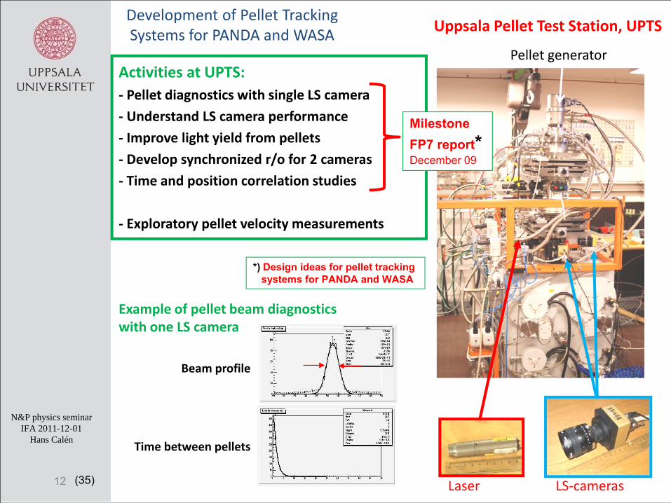
Uppsala Pellet Test Station, UPTS
Activities at UPTS:‐ Pellet diagnostics with single LS camera
‐ Understand LS camera performance
‐ Improve light yield from pellets
‐ Develop synchronized r/o for 2 cameras
‐ Time and position correlation studies
‐ Exploratory pellet velocity measurements
12 Laser LS‐cameras
Pellet generator
Development of Pellet Tracking Systems for PANDA and WASA
Example of pellet beam diagnostics with one LS camera
Beam profile
Time between pellets
Milestone FP7 report*December 09
*) Design ideas for pellet trackingsystems for PANDA and WASA
(35)
N&P physics seminarIFA 2011-12-01
Hans Calén
0
1
2
3
4
5
6
0 5 10 15 20 25Rel
ativ
e ve
loci
ty s
prea
d (%
)
Generation frequency (kHz)
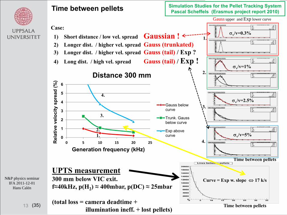
Distance 300 mm
Gauss below curve
Trunk. Gauss below curve
Exp above curve
Case: 1) Short distance / low vel. spread Gaussian !2) Longer dist. / higher vel. spread Gauss (trunkated)3) Longer dist. / higher vel. spread Gauss (tail) / Exp ?4) Long dist. / high vel. spread Gauss (tail) / Exp !
13
Gauss upper and Exp lower curve
1.
2.
4.
3.
1.2.
3.
4.
Time between pellets
Curve = Exp w. slope ⇔ 17 k/s
UPTS measurement300 mm below VIC exit.f≈40kHz, p(H2) ≈ 400mbar, p(DC) ≈ 25mbar
(total loss = camera deadtime + illumination ineff. + lost pellets)
Time between pellets
Time between pellets
σv/v=0.3%
σv/v=1%
σv/v=2.5%
σv/v=5%
Simulation Studies for the Pellet Tracking SystemPascal Scheffels (Erasmus project report 2010)
(35)
N&P physics seminarIFA 2011-12-01
Hans Calén
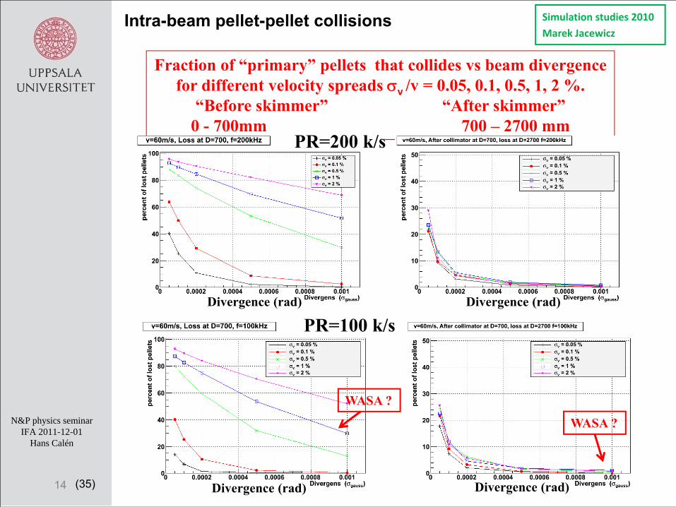
Fraction of “primary” pellets that collides vs beam divergencefor different velocity spreads σv /v = 0.05, 0.1, 0.5, 1, 2 %.
“Before skimmer” “After skimmer”0 - 700mm 700 – 2700 mm
14
Intra-beam pellet-pellet collisions Simulation studies 2010
Marek Jacewicz
PR=100 k/sDivergence (rad)
Divergence (rad)Divergence (rad)
Divergence (rad)
WASA ?
WASA ?
PR=200 k/s

(35)
N&P physics seminarIFA 2011-12-01
Hans Calén
135 degrees laser illumination geometry (refraction)
Two‐cameras setup. Synchronized measurement of x and z
Cameras A&B
laser beam exit
15
Develop synchronized r/o for 2 cameras
A
B
(35)
N&P physics seminarIFA 2011-12-01
Hans Calén
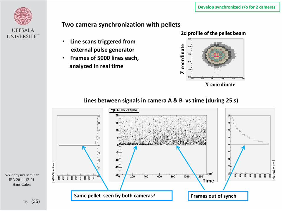
Two camera synchronization with pellets
• Line scans triggered fromexternal pulse generator
• Frames of 5000 lines each,analyzed in real time
Lines between signals in camera A & B vs time (during 25 s)
16
2d profile of the pellet beam
X coordinate
Z c
oord
inat
e
Develop synchronized r/o for 2 cameras
Same pellet seen by both cameras? Frames out of synch
Time
(35)
N&P physics seminarIFA 2011-12-01
Hans Calén
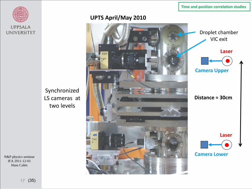
UPTS April/May 2010
Synchronized LS cameras at two levels
17
Laser
Camera Upper
Laser
Camera Lower
Distance ≈ 30cm
Droplet chamberVIC exit
Time and position correlation studies
(35)
N&P physics seminarIFA 2011-12-01
Hans Calén
18
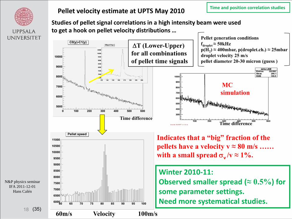
Studies of pellet signal correlations in a high intensity beam were used to get a hook on pellet velocity distributions …
Pellet velocity estimate at UPTS May 2010
Indicates that a “big” fraction of the pellets have a velocity v ≈ 80 m/s ……with a small spread σv /v ≈ 1%.
MC simulation
60m/s Velocity 100m/s
Time difference
ΔT (Lower-Upper) for all combinations of pellet time signals
Time difference
Pellet generation conditions fdroplet ≈ 50kHzp(H2) ≈ 400mbar, p(droplet.ch.) ≈ 25mbardroplet velocity 25 m/spellet diameter 20-30 micron (guess )
Winter 2010‐11: Observed smaller spread (≈ 0.5%) for some parameter settings.Need more systematical studies.
Time and position correlation studies

(35)
N&P physics seminarIFA 2011-12-01
Hans Calén
141618202224262830
250 350 450 550
Droplet velocity (m
/s)
Driving pressure P_H2 (mbar)
f=40227 Hz
f=47616 Hz
f=65732 Hz
19
Measurements at UPTS September 2010
Higher driving pressure⇒ faster (and bigger droplets)⇒ slower pellets
Droplet velocity vs driving pressure andgeneration frequency
Pellet generation conditions p(droplet.ch.) ≈ 25mbarpellet diameter 25-35 micron (guess )
Time and position correlation studies
70
75
80
85
90
95
100
250 350 450 550
Pellet v
elocity (m
/s)
Driving pressure P_H2 (mbar)
f=40227 Hz
f=47616 Hz
f=65732 Hz
Pellet velocity from LS‐camera info
Δφ/φ ≈1% ⇔ Δv /v ≈ 1.5%
Studies winter 2010‐11:
Higher dropchamber pressure(gas flow through VIC)⇒ faster pellets
ΔPDC/PDC ≈1% ⇔ Δv /v ≈ 0.3%
Variation over beam profile:Δv /v a few permille
(35)
N&P physics seminarIFA 2011-12-01
Hans Calén
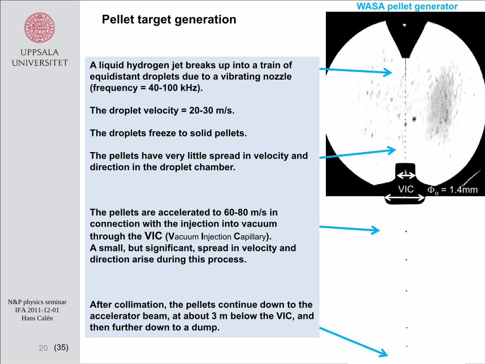
A liquid hydrogen jet breaks up into a train of equidistant droplets due to a vibrating nozzle (frequency = 40-100 kHz).
The droplet velocity = 20-30 m/s.
The droplets freeze to solid pellets.
The pellets have very little spread in velocity and direction in the droplet chamber.
The pellets are accelerated to 60-80 m/s in connection with the injection into vacuum through the VIC (Vacuum Injection Capillary). A small, but significant, spread in velocity and direction arise during this process.
After collimation, the pellets continue down to the accelerator beam, at about 3 m below the VIC, and then further down to a dump.
Pellet target generationWASA pellet generator
VIC Φo = 1.4mm
20
(35)
N&P physics seminarIFA 2011-12-01
Hans Calén
21
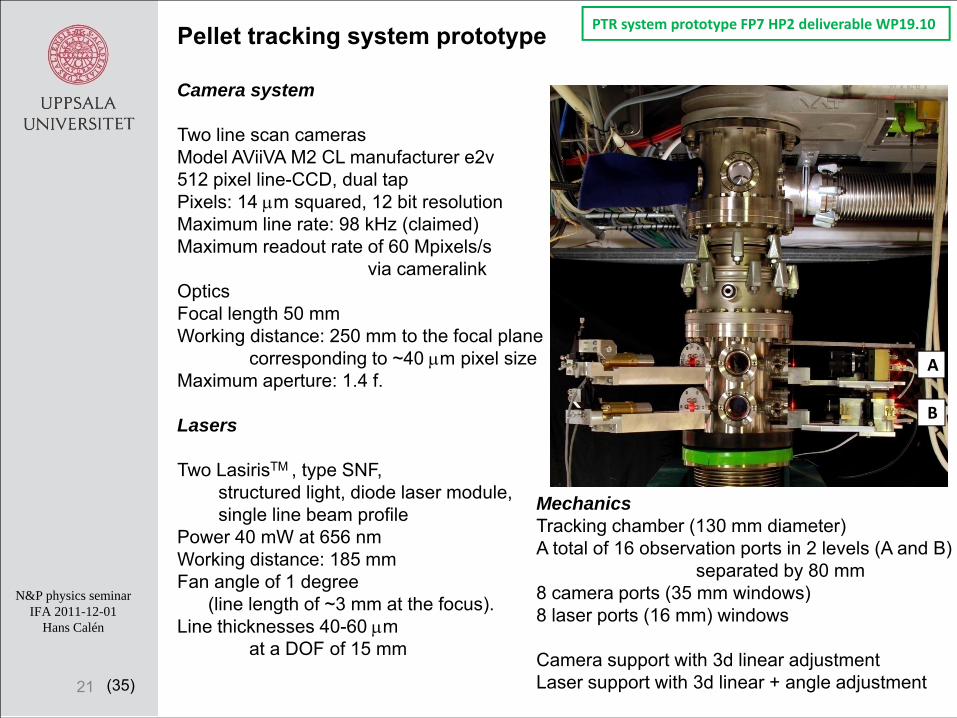
PTR system prototype FP7 HP2 deliverable WP19.10 Pellet tracking system prototype
Camera system
Two line scan camerasModel AViiVA M2 CL manufacturer e2v512 pixel line-CCD, dual tapPixels: 14 μm squared, 12 bit resolutionMaximum line rate: 98 kHz (claimed)Maximum readout rate of 60 Mpixels/s
via cameralinkOpticsFocal length 50 mmWorking distance: 250 mm to the focal plane
corresponding to ~40 μm pixel sizeMaximum aperture: 1.4 f.
Lasers
Two LasirisTM , type SNF, structured light, diode laser module, single line beam profile
Power 40 mW at 656 nmWorking distance: 185 mmFan angle of 1 degree
(line length of ~3 mm at the focus). Line thicknesses 40-60 μm
at a DOF of 15 mm
MechanicsTracking chamber (130 mm diameter)A total of 16 observation ports in 2 levels (A and B)
separated by 80 mm8 camera ports (35 mm windows) 8 laser ports (16 mm) windows
Camera support with 3d linear adjustmentLaser support with 3d linear + angle adjustment
B
A

(35)
N&P physics seminarIFA 2011-12-01
Hans Calén
22
PTR system prototype FP7 HP2 deliverable WP19.10
Readout2 frame grabbers, model mvTITAN-CL, PCI card, manufacturer: Matrix vision.Line synchronization and trigger by external gate generator in NIMMaximum line rate with continuous readout: ~50 kHz, limited by pci bus capacityWith triggered frames ~80 kHzSoftwareMonitoring and control software from manufactures.Readout C++ software based on Matrix vision software development kit and root.
Camera links120 Mbytes/s each
Framegrabbers:MatrixVision TitanCLPCI-board
NIM – Modules to generate synchronization signals for the line sweep of the cameras
DAQComputer
Pulse generators:
for LEDs (for control and monitoring of camera synchronization)
for Camera cycle
(35)
N&P physics seminarIFA 2011-12-01
Hans Calén
23
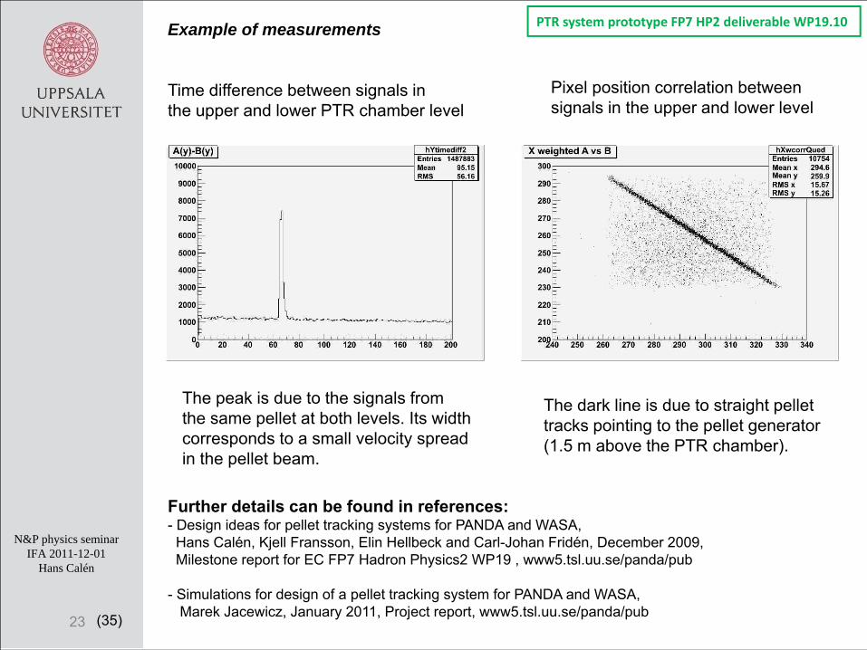
PTR system prototype FP7 HP2 deliverable WP19.10 Example of measurements
Time difference between signals in the upper and lower PTR chamber level
Pixel position correlation between signals in the upper and lower level
The dark line is due to straight pellet tracks pointing to the pellet generator (1.5 m above the PTR chamber).
The peak is due to the signals fromthe same pellet at both levels. Its widthcorresponds to a small velocity spreadin the pellet beam.
Further details can be found in references:- Design ideas for pellet tracking systems for PANDA and WASA,
Hans Calén, Kjell Fransson, Elin Hellbeck and Carl-Johan Fridén, December 2009, Milestone report for EC FP7 Hadron Physics2 WP19 , www5.tsl.uu.se/panda/pub
- Simulations for design of a pellet tracking system for PANDA and WASA, Marek Jacewicz, January 2011, Project report, www5.tsl.uu.se/panda/pub
(35)
N&P physics seminarIFA 2011-12-01
Hans Calén
Planned HP3 activities: Multi‐camera system
Camera A
Camera B
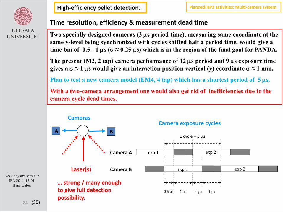
1 cycle = 3 µs
0.5 µs 0.5 µs1 µs 1 µs
exp 1
exp 2exp 1
exp 2
Two specially designed cameras (3 μs period time), measuring same coordinate at the same y-level being synchronized with cycles shifted half a period time, would give a time bin of 0.5 - 1 μs (σ ≈ 0.25 μs) which is in the region of the final goal for PANDA.
The present (M2, 2 tap) camera performance of 12 μs period and 9 μs exposure time gives a σ ≈ 1 μs would give an interaction position vertical (y) coordinate σ ≈ 1 mm.
Plan to test a new camera model (EM4, 4 tap) which has a shortest period of 5 μs.
With a two-camera arrangement one would also get rid of inefficiencies due to the camera cycle dead times.
A
Laser(s)
Cameras
Time resolution, efficiency & measurement dead time
B
24
… strong / many enough to give full detection possibility.
Camera exposure cycles
High‐efficiency pellet detection.

(35)
N&P physics seminarIFA 2011-12-01
Hans Calén
25
Generator floor with onelevel for two cams (x,y) and one laser at 135 deg.
Windows center positionvertical distance (mm)
‐76.5 DC 0 VIC exit
273.5 PTR gen
1503.5 Skimmer 0
1843.5 PTR upper 340
1923 PTR lower 419.5
(2690 Cosy beam 1166.5)
PTR at UPTSPresent measurement levels.. planned extension 2012.
Dump floor with twolevels for 2‐4 cams (x,y) with lasers at 135 deg.
Dump floor at top of skimmer one level for one cam (x or y) and one laser at 90 deg.
.. add possibility for one more laser at 135 deg.
.. add possibility for two lasers at 135 deg.
Below VIC one level for a cam and a laser at 90 deg.
(35)
N&P physics seminarIFA 2011-12-01
Hans Calén
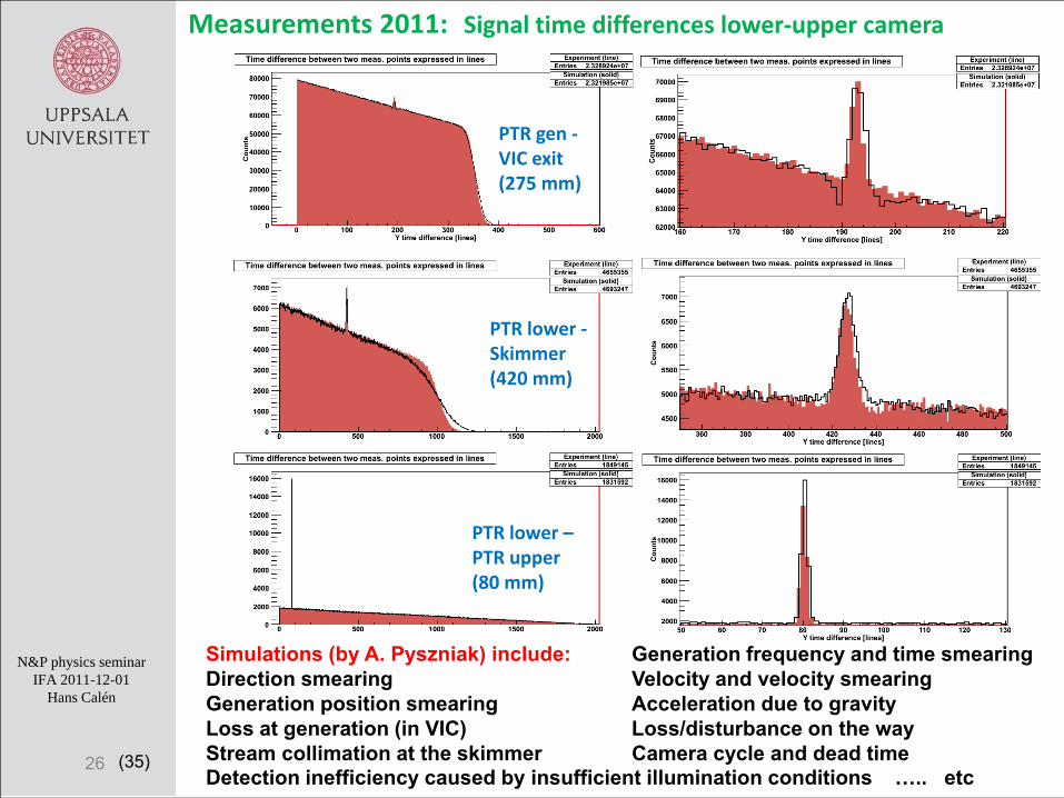
Measurements 2011: Signal time differences lower‐upper camera
26
Simulations (by A. Pyszniak) include: Generation frequency and time smearingDirection smearing Velocity and velocity smearingGeneration position smearing Acceleration due to gravityLoss at generation (in VIC) Loss/disturbance on the wayStream collimation at the skimmer Camera cycle and dead timeDetection inefficiency caused by insufficient illumination conditions ….. etc
PTR gen ‐VIC exit(275 mm)
PTR lower ‐Skimmer (420 mm)
PTR lower –PTR upper(80 mm)
(35)
N&P physics seminarIFA 2011-12-01
Hans Calén
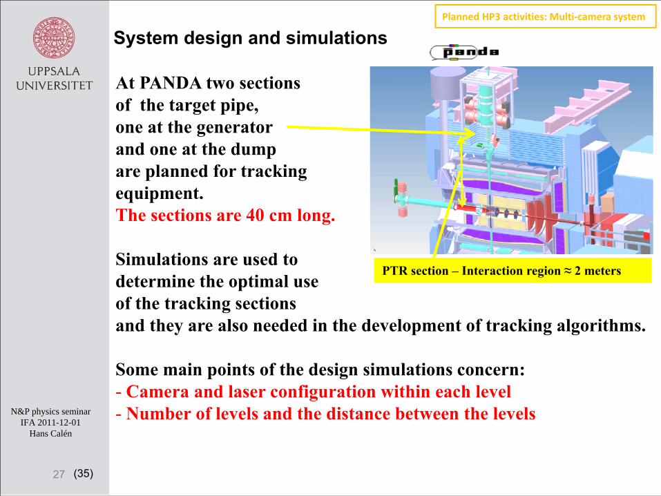
At PANDA two sections of the target pipe, one at the generator and one at the dump are planned for tracking equipment. The sections are 40 cm long.
Simulations are used to determine the optimal use of the tracking sectionsand they are also needed in the development of tracking algorithms.
Some main points of the design simulations concern:- Camera and laser configuration within each level- Number of levels and the distance between the levels
System design and simulations
PTR section – Interaction region ≈ 2 meters
27
Planned HP3 activities: Multi‐camera system
(35)
N&P physics seminarIFA 2011-12-01
Hans Calén
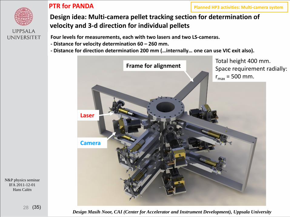
Design idea: Multi‐camera pellet tracking section for determination of velocity and 3‐d direction for individual pellets
28
Four levels for measurements, each with two lasers and two LS‐cameras.‐ Distance for velocity determination 60 – 260 mm.‐ Distance for direction determination 200 mm (…internally… one can use VIC exit also).
Design Masih Noor, CAI (Center for Accelerator and Instrument Development), Uppsala University
Total height 400 mm.Space requirement radially: rmax = 500 mm.
Laser
Camera
Frame for alignment
Planned HP3 activities: Multi‐camera systemPTR for PANDA
(35)
N&P physics seminarIFA 2011-12-01
Hans Calén
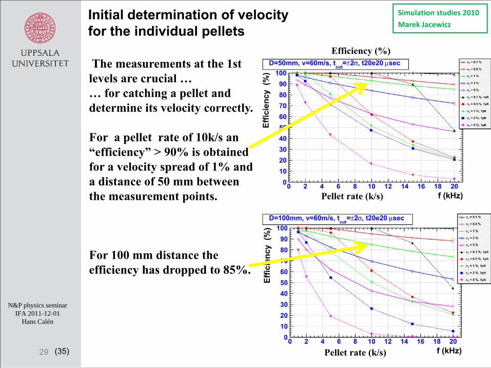
The measurements at the 1st levels are crucial … … for catching a pellet and determine its velocity correctly.
For a pellet rate of 10k/s an “efficiency” > 90% is obtained for a velocity spread of 1% and a distance of 50 mm between the measurement points.
For 100 mm distance the efficiency has dropped to 85%.
Initial determination of velocity for the individual pellets
29 Pellet rate (k/s)
Pellet rate (k/s)
Efficiency (%)
Simulation studies 2010
Marek Jacewicz
(35)
N&P physics seminarIFA 2011-12-01
Hans Calén
30
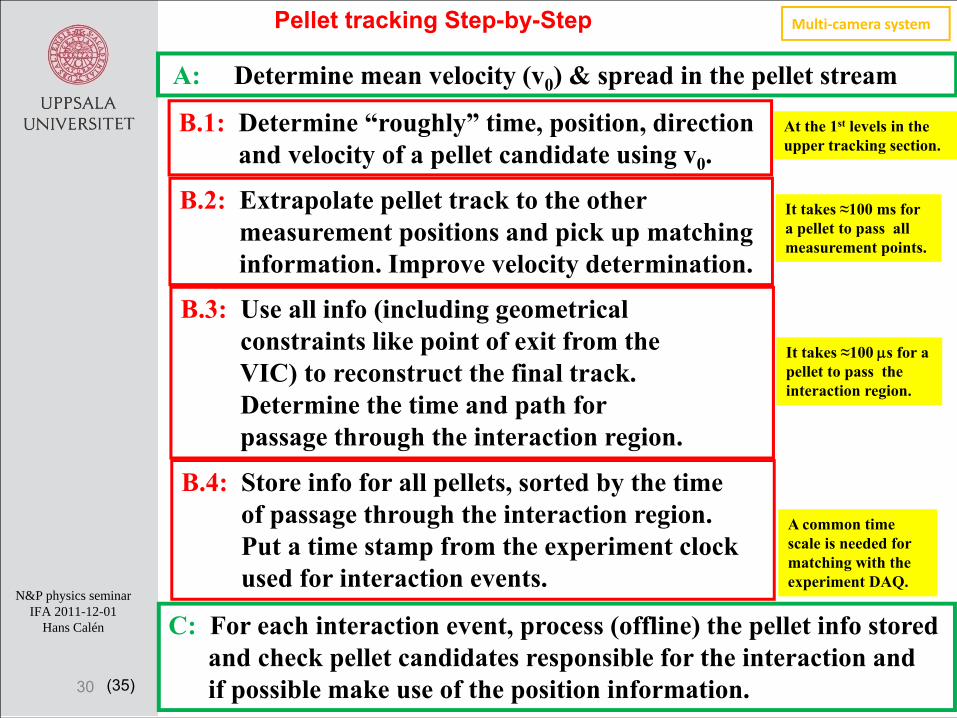
B.1: Determine “roughly” time, position, directionand velocity of a pellet candidate using v0.
C: For each interaction event, process (offline) the pellet info storedand check pellet candidates responsible for the interaction and if possible make use of the position information.
A: Determine mean velocity (v0) & spread in the pellet stream
Pellet tracking Step-by-Step
B.2: Extrapolate pellet track to the other measurement positions and pick up matchinginformation. Improve velocity determination.
B.3: Use all info (including geometricalconstraints like point of exit from the VIC) to reconstruct the final track. Determine the time and path for passage through the interaction region.
B.4: Store info for all pellets, sorted by the time of passage through the interaction region. Put a time stamp from the experiment clockused for interaction events.
At the 1st levels in the upper tracking section.
It takes ≈100 ms for a pellet to pass all measurement points.
It takes ≈100 μs for a pellet to pass the interaction region.
A common time scale is needed for matching with the experiment DAQ.
Multi‐camera system
(35)
N&P physics seminarIFA 2011-12-01
Hans Calén
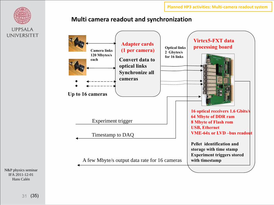
Multi camera readout and synchronization
31
Adapter cards(1 per camera)Camera links
120 Mbytes/seach
Optical links2 Gbytes/sfor 16 links
Convert data to optical linksSynchronize all cameras
16 optical receivers 1.6 Gbits/s64 Mbyte of DDR ram8 Mbyte of Flash romUSB, EthernetVME-64x or LVD –bus readout
Pellet identification and storage with time stampExperiment triggers stored with timestamp
Experiment trigger
Timestamp to DAQ
A few Mbyte/s output data rate for 16 cameras
Up to 16 cameras
Virtex5-FXT dataprocessing board
Planned HP3 activities: Multi‐camera readout system
(35)
N&P physics seminarIFA 2011-12-01
Hans Calén
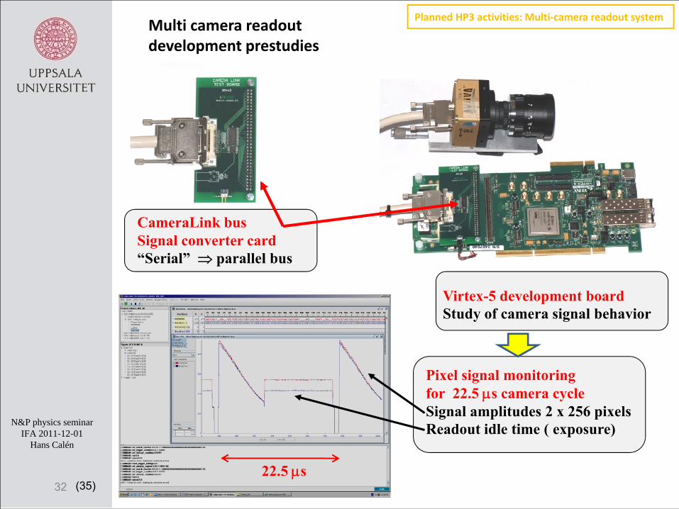
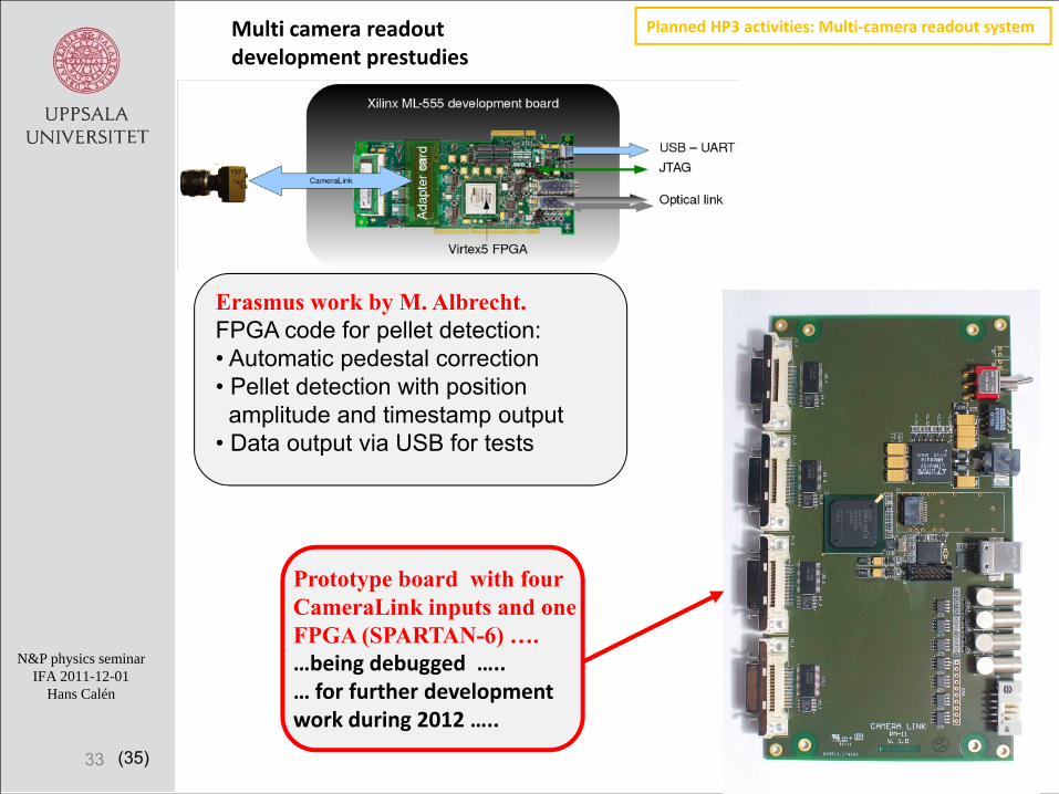
Multi camera readout development prestudies
32
CameraLink busSignal converter card “Serial” ⇒ parallel bus
Virtex-5 development board Study of camera signal behavior
Pixel signal monitoring for 22.5 μs camera cycleSignal amplitudes 2 x 256 pixels Readout idle time ( exposure)
22.5 μs
Planned HP3 activities: Multi‐camera readout system
(35)
N&P physics seminarIFA 2011-12-01
Hans Calén
Multi camera readout development prestudies
33
Erasmus work by M. Albrecht. FPGA code for pellet detection:• Automatic pedestal correction • Pellet detection with position
amplitude and timestamp output• Data output via USB for tests
Planned HP3 activities: Multi‐camera readout system
Prototype board with four CameraLink inputs and one FPGA (SPARTAN-6) ….…being debugged …..… for further development work during 2012 …..

(35)
N&P physics seminarIFA 2011-12-01
Hans Calén
Plan for the pellet tracking system developments 2011-2016
34
FP7 HP2-3 (personnel+mtrl)JU PhD studentSRC (personnel+mtrl)JCHP-FFE (personnel)Need for new funding (personnel+equipm)(UPTS at TSL)
(35)
N&P physics seminarIFA 2011-12-01
Hans Calén
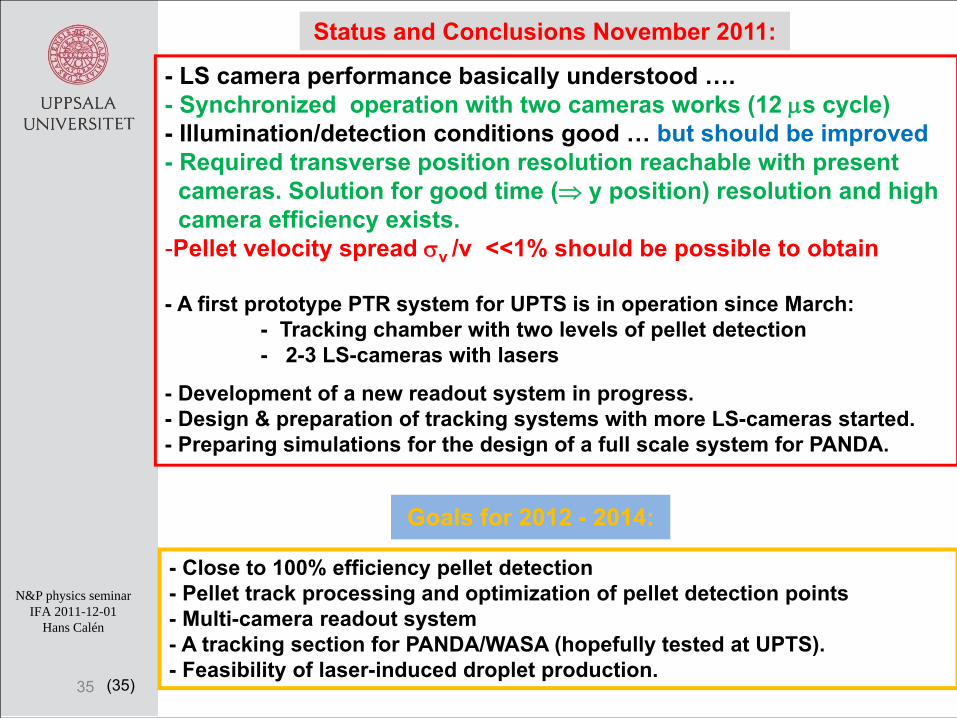
Status and Conclusions November 2011:
35
- LS camera performance basically understood ….- Synchronized operation with two cameras works (12 μs cycle)- Illumination/detection conditions good … but should be improved- Required transverse position resolution reachable with present cameras. Solution for good time (⇒ y position) resolution and high camera efficiency exists.
-Pellet velocity spread σv /v <<1% should be possible to obtain
- A first prototype PTR system for UPTS is in operation since March:- Tracking chamber with two levels of pellet detection- 2-3 LS-cameras with lasers
- Development of a new readout system in progress.- Design & preparation of tracking systems with more LS-cameras started.- Preparing simulations for the design of a full scale system for PANDA.
- Close to 100% efficiency pellet detection- Pellet track processing and optimization of pellet detection points- Multi-camera readout system- A tracking section for PANDA/WASA (hopefully tested at UPTS).- Feasibility of laser-induced droplet production.
Goals for 2012 - 2014: