performance analysis of a vapour compression-absorption cascaded refrigeration … ·...
TRANSCRIPT

Abstract
In a present study, the performance of a vapourcompression–absorption cascaded refrigeration sys-tem (CRS) under fouled conditions was analysed.The main effect of fouling is to decrease the effec-tiveness of the heat exchanger. Thus, the overallconductance (UA) of the heat exchanger isdecreased. Hence, another interpretation of foulingis to reduce the effective size of the heat exchanger.In the present work, the percentage decrease in theoverall conductance value (UA) of evaporator andcondenser due to their fouling is varied from 0 to50% and its consequences on various aspects ofCRS are generated to ascertain any possible pat-terns. The detailed first law analysis reveals that fora clean evaporator and condenser, the electricityconsumption is 67.5% less than vapour compres-sion system (VCS) for the same cooling capacity.CRS is able to save only 61.3% of electrical energywhen evaporator and condenser conductance isreduced by 50% due to fouling. Evaporator andcondenser fouling decreased the COP and rationalefficiency of the system by 4.7% and 10.5% respec-tively. It is also important to note that irreversibilityin the evaporator and condenser is increased by42.4% and 62.1% respectively, when their individ-ual performance is degraded by 50% due to foul-ing.
Keywords: fouling, vapour compression, absorp-tion, cascaded refrigeration system, first law, secondlaw analysis
1. IntroductionVapour compression refrigeration systems are com-monly used in a variety of commercial and industri-al applications due to their high cooling capacity atlow temperature, but to run these systems, highgrade energy is required. High grade energy or elec-trical energy is one of the major inputs for the eco-nomic development of any country. It is the basicneed and backbone of human activities in all sec-tors (industry, agriculture, transportation, etc.).Therefore, for sustainable development, high gradeenergy should be conserved and the utilization ofrenewable sources should be encouraged.Electricity consumption in vapour compressionrefrigeration systems can be reduced by cascading itwith a vapour absorption system (VAS) as theysimultaneously use both the high and low gradeenergy for refrigeration. Further, non-conventionalsources of energy such as solar and geothermal canalso be used to supply low grade energy for this sys-tem.
Cimsit and Ozturk (2012) determined that 48-51% less electrical energy is required in the cascad-ed refrigeration cycle as compared to the classicalvapour compression refrigeration cycle. Wang et al.(2012) analysed the cascaded system using solarenergy to supply heat in the generator and reportedabout 50% lower electricity consumption in the cas-caded system. Fernandez-Seara et al. (2006) evalu-ated its adaptability in a cogeneration system andobtained a COP of 2.602 in the compression sec-tion. Seyfouri and Ameri (2012) showed that a cas-
Journal of Energy in Southern Africa • Vol 25 No 4 • November 2014 23
Performance analysis of a vapour compression-absorptioncascaded refrigeration system with undersized evaporatorand condenser
Vaibhav JainDepartment of Mechanical and Automation Engineering, MAIT, Delhi, India
Gulshan SachdevaDepartment of Mechanical Engineering, NIT, Kurukshetra, India
Surendra S KachhwahaSchool of Technology, Department of Mechanical Engineering, PDPU, Gandhinagar, India
caded system is more efficient and less energy con-suming than a compression system to generatecooling at low temperature. Garimella et al. (2011)used a cascaded compression-absorption cycle for anaval ship application with a high temperature liftand observed 31% electrical energy reduction.Other researchers (Chinnappa et al., 1993; Kai-rouani and Nehdi, 2006) have also analysed thepotential of CRS to reduce electrical energy con-sumption compared to conventional VCS.
Published literature reveals that the CRS is anal-ysed without considering the fouling conditions(rust formation and deposition of fluid impurities onheat transfer surfaces). These surface depositsincrease thermal resistance, which reduce heattransfer, may impede fluid flow, and increase pres-sure drop across the heat exchanger which dropsthe overall performance of heat exchanger equip-ment. Therefore, fouling in the heat exchanger will
increase the energy consumption and/or decreasecooling capacity along with the system efficiency.The main effect of fouling is to decrease the effec-tiveness of the heat exchanger. Thus, the overallconductance (UA) of the heat exchanger isdecreased. Hence, another interpretation of foulingis to reduce the effective size of the heat exchanger.Ali and Ismail (2008) experimentally investigatedthe performance of a room air conditioner consid-ering the evaporator fouling. The COP of the sys-tem was reduced by 43.6% with 330 gm of foulingmaterials. Pak et al. (2005) conducted an experi-mental study to investigate the effects of air-sidefouling on the performance of various condensercoils used in the air conditioning system and foundthat the pressure drop was increased by 22 to 37%,and heat transfer performance was decreased by 4to 5% for the double row heat exchangers. Bultmanet al. (1993) found that the COP of VCS was
24 Journal of Energy in Southern Africa • Vol 25 No 4 • November 2014
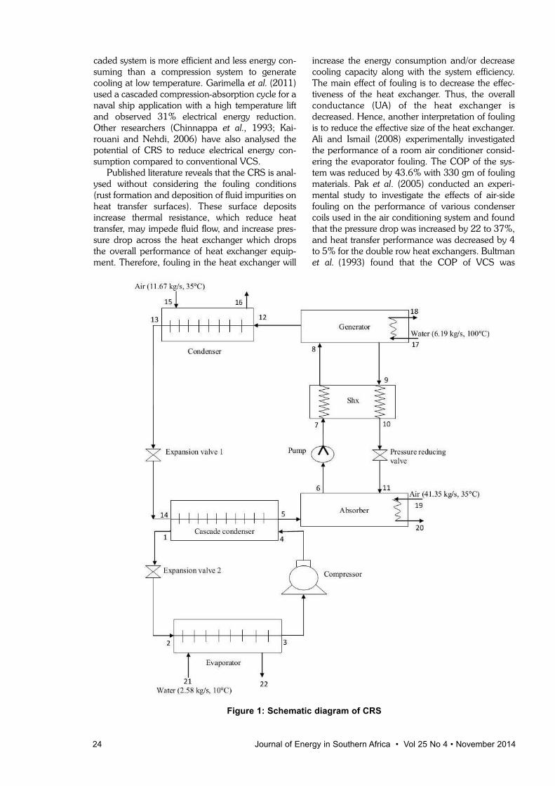
Figure 1: Schematic diagram of CRS

decreased by 7.6% when the air flow across thecondenser was reduced by 40% for a constantspeed fan. Bell and Groll (2011) experimentallyobserved 200% increment in air side pressure dropin a plate fin and micro channel coils while com-paring clean and fouled conditions. Qureshi andZubair (2011) developed a mathematical model tostudy the performance of a vapour compressionrefrigeration system under fouled conditions withalternative refrigerants.
Cascaded refrigeration systems can help to saveelectrical energy but relevant practical issues needto be understood (such as consequences of fouling)to ascertain these effects if such systems are to beemployed in the future. Despite the importance ofheat exchanger performance degradation due tofouling in a cascaded refrigeration system, adetailed analysis has not been found in the litera-ture. Therefore, the objective of this paper is to pres-ent the effects of the consequences of condenserand evaporator outside fouling on the performanceof a vapour compression-absorption cascadedrefrigeration system as well as carry out an in-depthanalysis of the data generated to ascertain any pos-sible patterns. For this purpose, a property-depend-ent thermodynamic model that includes energy aswell as exergy analysis was used. The exergy analy-sis is important along with the energy analysis forthe process improvement of any refrigeration sys-tem (Sayyaadi and Nejatolahi, 2011). Exergyanalysis accounts for the irreversibilities existing dueto the finite temperature difference in the heatexchangers as well as the losses due to the non-isen-tropic compression and expansion in the compres-sors and the expansion valves, respectively.
2. Theoretical formulation of vapourcompression-absorption cascadedrefrigeration system2.1 System selection
Figure 1 shows a vapour compression–absorptioncascaded refrigeration system. In CRS, VCS and thesingle effect VAS are thermally connected in seriesby means of a heat exchanger called the cascadecondenser. The evaporator of the compression sec-tion absorbs the refrigeration load from the water, tobe cooled. The heat absorbed by the evaporatorand the work input of the compressor is supplied tothe evaporator of the absorption section in the cas-cade condenser. R22 and LiBr-Water are used asworking fluid in the compression and absorptionsection respectively. The condenser and absorber ofthe proposed CRS are air cooled. The low pressureliquid refrigerant (water) of the absorption section isconverted into vapour (steam) by absorbing theheat in the cascade condenser. This low pressurecold vapours i.e. steam is absorbed by the hot solu-tion of LiBr in the absorber. The heat generated inthe absorber is carried out by the circulating air.
This weak solution of LiBr, being rich in refrigerantvapour, is pumped to the generator through a heatexchanger. The pump work is negligible as com-pared to the compressor work of the compressionsection as the specific volume of the liquid isextremely small compared to that of vapour. Themain energy consumption in the absorption sectionis only in the generator in the form of low gradeenergy. Water (refrigerant) gets boils in the genera-tor due to heat transfer. Since the salt does not exertany vapour pressure, the vapour leaving the gener-ator is a pure ‘refrigerant’ (water vapour).Therefore, the analyser and dephlegmator do notform a part of the system. This high pressure watervapour is condensed in an air cooled condenser.The solution returning from the generator is astrong solution of LiBr in water. The pressure of thisstrong solution is reduced to absorber pressurethrough a pressure reducing valve.
2.2 Thermodynamic modelling of the vapour
compression-absorption cascaded
refrigeration system
The following assumptions are made in modellingthe CRS (Cimsit and Ozturk, 2012):1. The system is in a steady state.2. All the pressure losses in different components of
the system are neglected.3. Heat loss in the suction and liquid lines are neg-
lected in this work.4. Refrigerant at the exit of the evaporator, cascade
condenser and condenser is saturated vapour.5. Isentropic efficiency of compressor is assumed
as constant.6. The processes occurring in the expansion valves
are isenthalpic.
Journal of Energy in Southern Africa • Vol 25 No 4 • November 2014 25
2.3 Model validation
The thermodynamic model equations given inTable 1 are highly nonlinear in nature and havebeen solved numerically in Engineering EquationSolver (EES). The thermophysical properties of
refrigerants are taken from built-in functions. InCRS, VCS and VAS are connected in series wherecondenser of the compression section rejects heat tothe evaporator of the absorption section. Models ofVCS, VAS and CRS are individually validated.
Qureshi and Zubair (2011) have studied theeffect of fouling on VCS using R134a as refrigerant.Table 2 shows the comparison of the current modelresults with Qureshi and Zubair (2011) for sameinput conditions. The percentage error in the resultsis within 0.03%.
The results of the thermodynamic model of VASare compared with those by Kaynakli and Kilic(2007). The following set of data is used to gener-ate the results for comparison purposes: Tcond =35°C, Ta = 40°C, Tg = 90°C, Tevap = 5°C, Qevap =10 kW, ηp = 0.95 and ε = 0.7. Water-LiBr is con-sidered as the working pair. The percentage errorfound in the prediction of COP is 2.60%. The largeerror in prediction of COP is due to usage of differ-ent correlations to determine the thermophysicalproperties of Water-LiBr. In this paper, the thermo-physical properties of Water-LiBr are taken frombuilt-in functions of EES.
Data from the work of Cimsit and Ozturk (2012)related to CRS was also used for the verification ofthe current CRS model. The following set of datawas used to generate the results for comparisonpurposes: Tcond = 40°C, Ta = 40°C, Tg = 90°C,Tevap = 10°C, Qevap = 50 kW, ηp = 0.90, ηisen =0.80 and ε = 0.6. Water-LiBr is assumed as theworking fluid in the absorption section and R134ais considered in the compression section. The max-imum error in the prediction of calculated parame-ters is found to be 1.6% (Table 3).
3. Results and discussionThe thermodynamic model has been applied toevaluate the performance of a typical CRS asshown in Figure 1. The values of inputs as obtainedby the literature survey are given in Table 4.Thermodynamic properties at inlet and outlet ofeach component of the CRS are presented in Table5 for clean conditions. The main purpose of a CRSis to reduce the consumption of electricity in thecompressor of the vapour compression section. Thisis done by lowering the temperature of the con-denser of VCS. The following values can be pre-dicted for VCS operating under the same conditionsas mentioned in Table 4: Tevap = 0.4°C, Tcond =46.8°C, mref = 0.5687 kg/s, ηv = 95.33%, W =27.94 kW, Qcond = 111.03 kW and COP = 2.972.
When we compare the performance of a CRSwith a VCS operating under the same conditions(Table 4), it can be shown that refrigerant (R22)mass flow rate in CRS is reduced by 19.81%. Thepresent thermodynamic model predicts the con-denser and evaporator temperatures for both theVCS and the CRS. Based on the cooling capacity
26 Journal of Energy in Southern Africa • Vol 25 No 4 • November 2014
.
.
..
.

Journal of Energy in Southern Africa • Vol 25 No 4 • November 2014 27
Table 2: Comparison of performance data of the current model of VCS with Qureshi and Zubair (2011)
Condition mref mref,m error W Wm error Qevap Qevap,m error COP COPm error
(kg/s) (kg/s) (%) (kW) (kW) (%) (kW) (kW) (%) (%)
Clean condition 0.9067 0.9068 -0.01 60.109 60.113 -0.01 100 100 0.00 1.664 1.664 0.00
Evaporator fouling 0.7992 0.7993 -0.01 55.049 55.064 -0.03 88.84 88.85 -0.01 1.614 1.614 0.00
Condenser fouling 0.9140 0.914 0.00 64.142 64.154 -0.02 91.24 91.24 0.00 1.422 1.422 0.00
Both evaporator 0.8095 0.8095 0.00 58.580 58.598 -0.03 82.3 82.32 -0.02 1.405 1.405 0.00& condenser fouling
......
and the effectiveness of the evaporator, the evapo-rator temperature for the systems is 0.4°C. The pre-dicted condenser temperatures are 46.8°C and45.4°C for VCS and CRS respectively. The reduc-tion in the condenser temperature also gives a lowertemperature of air at the condenser exit after cool-ing. Table 6 represents the values of performanceparameters for the CRS.
Table 3: Comparison of performance data of thecurrent model of CRS with Cimsit and Ozturk
(2012)
Parameter Current CRS Cimsit and Error (%)model Ozturk (2012)
Qa (kW) 73.13 72.76 -0.51
Qg (kW) 76.79 76.45 -0.44
Qcond (kW) 61.20 61.06 -0.23
W (kW) 8.38 8.25 -1.58
COPVCS 5.963 6.061 1.62
COPVCAS 0.749 0.750 0.13
COPCRS 0.587 0.590 0.51
The generator heat transfer rate is 130.60 kWwhich is highest. The heat transfer rates in the con-denser and absorber are 98.04 kW and 124.70 kWrespectively. The effect of the pump on the totalenergy inputs is found to be negligible. The pre-scribed temperature (T5) for refrigerant (water
vapour) and degree of overlap are 10°C and 8°Crespectively in the cascade condenser. Thus, therefrigerant (R22) reached a temperature of 18°C atthe exit of the cascade condenser. The power con-sumption is reduced by 67.5% in the compressor ofCRS as compared to equivalent VCS. The volumet-ric efficiency of compressor is also increased by3.4%. As subsystems of CRS, COP of vapour com-pression and vapour absorption subsystems are9.173 and 0.705 respectively. Higher value of COPfor the vapour compression refrigeration subsystemis due to low refrigerant temperature at the com-pressor exit which leads to reduction in electricityrequirement of the compressor. The heat rejectionin the condenser of CRS is reduced by 11.6% ascompared to VCS.
Table 6 also shows the irreversibility rate of thesystem components. From an irreversibility ratepoint of view, the most sensitive component in com-pression and absorption sections of a CRS are com-pressor and generator. Their irreversibility con-tributes 15.5% and 19.4% respectively in total irre-versibility of system (at clean condition). It is alsoapparent that the most efficient components of aCRS are pump and pressure reducing valve inwhich approximate zero entropy generation isobserved. In the decreasing order of irreversibleloss, these components can be arranged in thesequence as generator, absorber, compressor, cas-cade condenser, condenser, evaporator, solutionheat exchanger, expansion valves, pump and pres-
28 Journal of Energy in Southern Africa • Vol 25 No 4 • November 2014
Table 4: Value of inputs in the model of the CRS
Parameters Values
Evaporator coolant inlet temperature (Tin,evap in ºC) 10
Evaporator coolant mass flow rate (mef,avap in kg/s) 2.58
Condenser coolant inlet temperature (Tin,cond in ºC) 35
Condenser coolant mass flow rate ( mef,cond in kg/s) 11.67
Generator coolant inlet temperature (Tin,g in ºC) 100
Generator coolant outlet temperature ( Tout,g in ºC) 95
Generator temperature (Tg in ºC) 90
Absorber coolant inlet temperature (Tin,a in ºC) 35
Absorber coolant outlet temperature (Tout,a in ºC) 38
Absorber temperature (Ta in ºC) 40
Rate of heat absorbed by evaporator (Qevap in kW) 83.09
Effectiveness of evaporator and condenser at clean condition (�) 0.8
Capacitance rate of external fluid at evaporator (Cevap in kW/K) 10.81
Capacitance rate of external fluid at condenser (Ccond in kW/K) 11.73
Temperature at exit of cascade condenser (T5 in ºC) 10
Effectiveness of shx (εshx) 0.6
Isentropic efficiency of compressors (ηisen) 0.65
Electrical efficiency of pump (ηp) 0.9
Degree of overlap in cascade condenser (Toverlap) in ºC) 8
Environmental temperature (To in ºC) 25
Atmospheric pressure (Po in kPa) 101.325
.
.
.
.
.
.
.
..

sure reducing valve. The total irreversibility rate forthe entire CRS and rational efficiency are 19.95 kWand 38.5% respectively.
The total fixed cost of the CRS increases due toaddition of VAS components, but the running costwill decrease due to small electricity consumption incompressor and utilization of low grade energy inthe generator. The hot water obtained from thesolar energy is assumed to be the source of heat forthe generator of VAS in the present analysis.
3.1 Effect of evaporator fouling
The effects of evaporator fouling on the perform-ance characteristics of CRS are shown in Figures 2to 4. Evaporator conductance is varied from 0 to50%, where 0 refers to clean condition. The maineffect of fouling is to decrease the value of UA,which in turn, decreases the effectiveness of theheat exchanger. The effectiveness of the evaporatorin a clean condition is assumed to be 0.8 and it isdecreased up to 0.55, when evaporator conduc-tance is reduced by 50%. It is observed from Figure2 that there is 31% reduction in its effectivenesswhich directly lowers the cooling capacity of the sys-tem. The reduction in evaporator effectivenesscaused the evaporator temperature to decreasefrom 0.4°C to -2.5°C, while keeping the inlet tem-perature of external fluid to be cooled as constant.Further, it also decreased the temperature of cas-
Journal of Energy in Southern Africa • Vol 25 No 4 • November 2014 29
Table 5: Value of thermodynamic properties at clean condition
State point T P m (R22) m (H2O) m (LiBr-H2O) m (Air) h s(ºC) (kPa) (kg/s) (kg/s) (kg/s) (kg/s) (kJ/kg) (kJ/kg/K)
1 18.0 860.50 0.4561 223.0 1.080
2 0.4 504.50 0.4561 223.0 1.084
3 0.4 504.50 0.4561 405.1 1.750
4 35.2 860.50 0.4561 425.0 1.773
5 10.0 1.228 0.0395 2519.0 8.899
6 40.0 1.228 0.5331 94.05 0.246
7 40.0 9.813 0.5331 94.06 0.246
8 66.4 9.813 0.5331 148.50 0.413
9 90.0 9.813 0.4936 211.10 0.512
10 60.0 9.813 0.4936 152.30 0.343
11 60.0 1.228 0.4936 152.30 0.343
12 90.0 9.813 0.0395 2668.0 8.404
13 45.4 9.813 0.0395 190.30 0.644
14 10.0 1.228 0.0395 190.30 0.674
15 35.0 101.325 11.67 308.60 5.729
16 43.3 101.325 11.67 317.0 5.756
17 100.0 101.325 6.1990 419.10 1.307
18 95.0 101.325 6.1990 398.0 1.250
19 35.0 101.325 41.35 308.60 5.729
20 38.0 101.325 41.35 311.60 5.738
21 10.0 101.325 2.580 42.09 0.151
22 2.3 101.325 2.580 9.88 0.035
Table 6: Value of performance parameters atclean condition
S. Performance parameters Value of clean no condition
1 Low grade energies Qcond (kW) 98.04Qa (kW) 124.70Qg (kW) 130.60Qevap (kW 83.09Qcascade (kW) 92.15
2 High grade energies W (kW) 9.05Wp (kW) 0.003
3 First law parameters COPCRS 0.594COPVCS 9.173COPVAS 0.705
4 Second law parameters Icomp (kW) 3.10Icascade (kW) 2.84Iev2 (kW) 0.50Ievap (kW) 1.89Ia (kW) 3.62Ip (kW) 0.001Ig (kW) 3.87Ishx (kW) 1.68Iprv (kW) 0Ievi (kW) 0.35Icond (kW) 2.04It (kW) 19.95ηR (%) 38.5
5 Other parameters 13.5ηv (%) 98.6
. . . .
...
..
..
..
.....
.
.
..
.
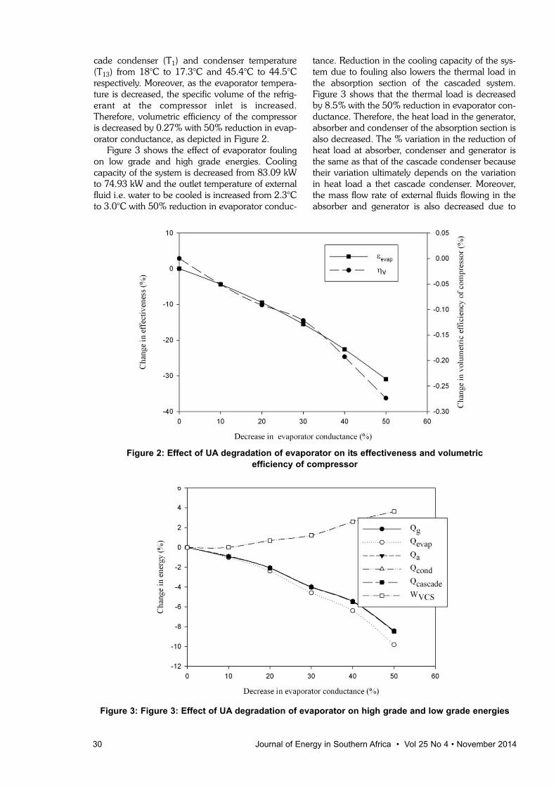
cade condenser (T1) and condenser temperature(T13) from 18°C to 17.3°C and 45.4°C to 44.5°Crespectively. Moreover, as the evaporator tempera-ture is decreased, the specific volume of the refrig-erant at the compressor inlet is increased.Therefore, volumetric efficiency of the compressoris decreased by 0.27% with 50% reduction in evap-orator conductance, as depicted in Figure 2.
Figure 3 shows the effect of evaporator foulingon low grade and high grade energies. Coolingcapacity of the system is decreased from 83.09 kWto 74.93 kW and the outlet temperature of externalfluid i.e. water to be cooled is increased from 2.3°Cto 3.0°C with 50% reduction in evaporator conduc-
tance. Reduction in the cooling capacity of the sys-tem due to fouling also lowers the thermal load inthe absorption section of the cascaded system.Figure 3 shows that the thermal load is decreasedby 8.5% with the 50% reduction in evaporator con-ductance. Therefore, the heat load in the generator,absorber and condenser of the absorption section isalso decreased. The % variation in the reduction ofheat load at absorber, condenser and generator isthe same as that of the cascade condenser becausetheir variation ultimately depends on the variationin heat load a thet cascade condenser. Moreover,the mass flow rate of external fluids flowing in theabsorber and generator is also decreased due to
30 Journal of Energy in Southern Africa • Vol 25 No 4 • November 2014
Figure 2: Effect of UA degradation of evaporator on its effectiveness and volumetric efficiency of compressor
Figure 3: Figure 3: Effect of UA degradation of evaporator on high grade and low grade energies
lower heat load. Lower heat load in the condenseralso caused a substantial drop of air temperature atcondenser exit. Increase in specific volume of refrig-erant at the compressor inlet due to evaporatorfouling increased the electric power consumption(compressor work) in compressor by 3.6%. Thepresent cascaded system saves 67.5% of compres-sor work in VCS at clean condition. But due to foul-ing, it would now be able to save 66.4% of com-pressor work.
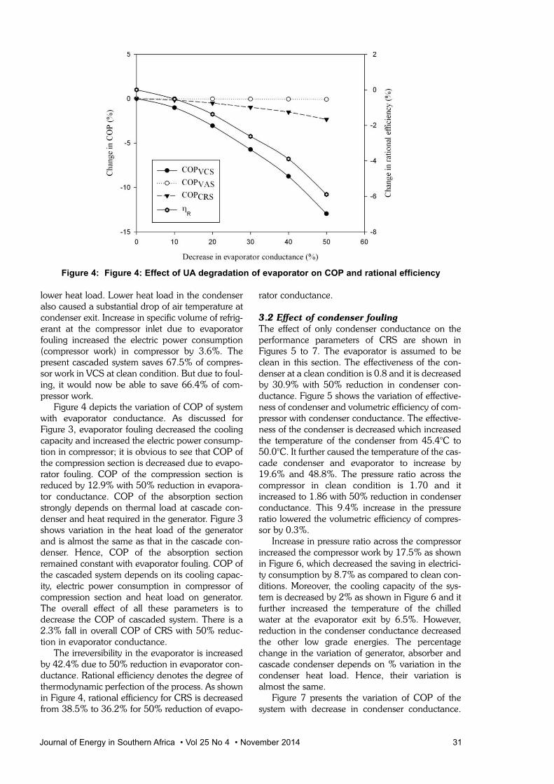
Figure 4 depicts the variation of COP of systemwith evaporator conductance. As discussed forFigure 3, evaporator fouling decreased the coolingcapacity and increased the electric power consump-tion in compressor; it is obvious to see that COP ofthe compression section is decreased due to evapo-rator fouling. COP of the compression section isreduced by 12.9% with 50% reduction in evapora-tor conductance. COP of the absorption sectionstrongly depends on thermal load at cascade con-denser and heat required in the generator. Figure 3shows variation in the heat load of the generatorand is almost the same as that in the cascade con-denser. Hence, COP of the absorption sectionremained constant with evaporator fouling. COP ofthe cascaded system depends on its cooling capac-ity, electric power consumption in compressor ofcompression section and heat load on generator.The overall effect of all these parameters is todecrease the COP of cascaded system. There is a2.3% fall in overall COP of CRS with 50% reduc-tion in evaporator conductance.
The irreversibility in the evaporator is increasedby 42.4% due to 50% reduction in evaporator con-ductance. Rational efficiency denotes the degree ofthermodynamic perfection of the process. As shownin Figure 4, rational efficiency for CRS is decreasedfrom 38.5% to 36.2% for 50% reduction of evapo-
rator conductance.
3.2 Effect of condenser fouling
The effect of only condenser conductance on theperformance parameters of CRS are shown inFigures 5 to 7. The evaporator is assumed to beclean in this section. The effectiveness of the con-denser at a clean condition is 0.8 and it is decreasedby 30.9% with 50% reduction in condenser con-ductance. Figure 5 shows the variation of effective-ness of condenser and volumetric efficiency of com-pressor with condenser conductance. The effective-ness of the condenser is decreased which increasedthe temperature of the condenser from 45.4°C to50.0°C. It further caused the temperature of the cas-cade condenser and evaporator to increase by19.6% and 48.8%. The pressure ratio across thecompressor in clean condition is 1.70 and itincreased to 1.86 with 50% reduction in condenserconductance. This 9.4% increase in the pressureratio lowered the volumetric efficiency of compres-sor by 0.3%.
Increase in pressure ratio across the compressorincreased the compressor work by 17.5% as shownin Figure 6, which decreased the saving in electrici-ty consumption by 8.7% as compared to clean con-ditions. Moreover, the cooling capacity of the sys-tem is decreased by 2% as shown in Figure 6 and itfurther increased the temperature of the chilledwater at the evaporator exit by 6.5%. However,reduction in the condenser conductance decreasedthe other low grade energies. The percentagechange in the variation of generator, absorber andcascade condenser depends on % variation in thecondenser heat load. Hence, their variation isalmost the same.
Figure 7 presents the variation of COP of thesystem with decrease in condenser conductance.
Journal of Energy in Southern Africa • Vol 25 No 4 • November 2014 31
Figure 4: Figure 4: Effect of UA degradation of evaporator on COP and rational efficiency
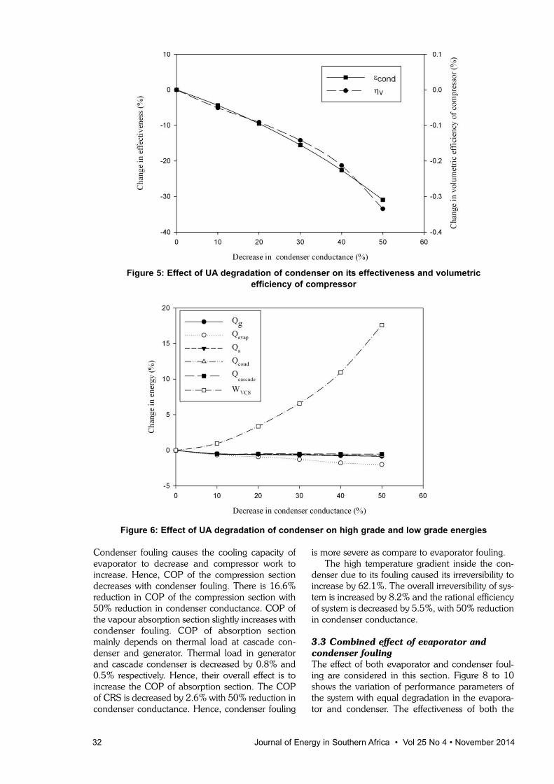
Condenser fouling causes the cooling capacity ofevaporator to decrease and compressor work toincrease. Hence, COP of the compression sectiondecreases with condenser fouling. There is 16.6%reduction in COP of the compression section with50% reduction in condenser conductance. COP ofthe vapour absorption section slightly increases withcondenser fouling. COP of absorption sectionmainly depends on thermal load at cascade con-denser and generator. Thermal load in generatorand cascade condenser is decreased by 0.8% and0.5% respectively. Hence, their overall effect is toincrease the COP of absorption section. The COPof CRS is decreased by 2.6% with 50% reduction incondenser conductance. Hence, condenser fouling
is more severe as compare to evaporator fouling.The high temperature gradient inside the con-
denser due to its fouling caused its irreversibility toincrease by 62.1%. The overall irreversibility of sys-tem is increased by 8.2% and the rational efficiencyof system is decreased by 5.5%, with 50% reductionin condenser conductance.
3.3 Combined effect of evaporator and
condenser fouling
The effect of both evaporator and condenser foul-ing are considered in this section. Figure 8 to 10shows the variation of performance parameters ofthe system with equal degradation in the evapora-tor and condenser. The effectiveness of both the
32 Journal of Energy in Southern Africa • Vol 25 No 4 • November 2014
Figure 5: Effect of UA degradation of condenser on its effectiveness and volumetric efficiency of compressor
Figure 6: Effect of UA degradation of condenser on high grade and low grade energies

components is decreased by 30.9% with 50%reduction in their conductance. It caused the tem-perature of the evaporator to decrease from 0.4°Cto -2.3°C, whereas the condenser temperature isincreased from 45.4°C to 48.8°C. It also increasedthe temperature of the cascade condenser from18°C to 20.6°C.
Figure 8 shows that the volumetric efficiency ofthe compressor is decreased by 0.6% with 50% re-duction in evaporator and condenser conductance.Reduction in the evaporator temperature furthercaused the specific volume of refrigerant to increaseby 9.9%. The pressure ratio across the compressorreached to 2.10 at this point. Hence, compressorwork is increased from 9.06 kW to 10.80 kW. Thus,
CRS is able to save only 61.3% of electric power ascompared to 67.5% in clean condition.
Figure 9 depicts that the variation in the thermalloads at the condenser, absorber, generator andcascade condenser and are almost the same. Thecooling capacity of the evaporator is decreased by10.9% and the heat rejected in the condenser is90.03 kW under this situation whereas this magni-tude was 97.32 kW under the case of condenserfouling only.
Figure 10 presents the variation of COP of thesystem with decrease in evaporator and condenserconductance. COP of the compression section isdecreased with reduction in evaporator and con-denser conductance. The trend is obvious due to
Journal of Energy in Southern Africa • Vol 25 No 4 • November 2014 33
Figure 7: Effect of UA degradation of condenser on COP and rational efficiency
Figure 8: Effect of UA degradation of evaporator and condenser on their effectiveness andvolumetric efficiency of compressor
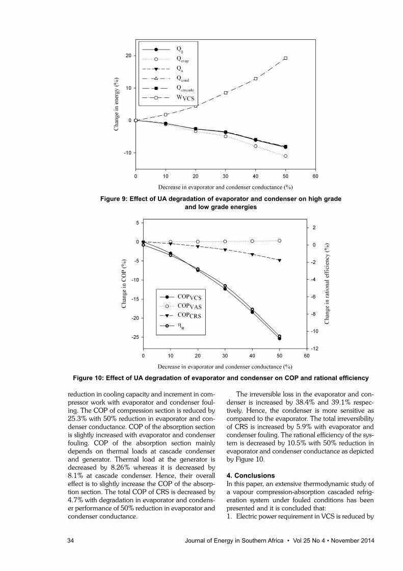
reduction in cooling capacity and increment in com-pressor work with evaporator and condenser foul-ing. The COP of compression section is reduced by25.3% with 50% reduction in evaporator and con-denser conductance. COP of the absorption sectionis slightly increased with evaporator and condenserfouling. COP of the absorption section mainlydepends on thermal loads at cascade condenserand generator. Thermal load at the generator isdecreased by 8.26% whereas it is decreased by8.1% at cascade condenser. Hence, their overalleffect is to slightly increase the COP of the absorp-tion section. The total COP of CRS is decreased by4.7% with degradation in evaporator and condens-er performance of 50% reduction in evaporator andcondenser conductance.
The irreversible loss in the evaporator and con-denser is increased by 38.4% and 39.1% respec-tively. Hence, the condenser is more sensitive ascompared to the evaporator. The total irreversibilityof CRS is increased by 5.9% with evaporator andcondenser fouling. The rational efficiency of the sys-tem is decreased by 10.5% with 50% reduction inevaporator and condenser conductance as depictedby Figure 10.
4. ConclusionsIn this paper, an extensive thermodynamic study ofa vapour compression-absorption cascaded refrig-eration system under fouled conditions has beenpresented and it is concluded that: 1. Electric power requirement in VCS is reduced by
34 Journal of Energy in Southern Africa • Vol 25 No 4 • November 2014
Figure 9: Effect of UA degradation of evaporator and condenser on high grade and low grade energies
Figure 10: Effect of UA degradation of evaporator and condenser on COP and rational efficiency

67.5%, when it is cascaded with an absorptionsystem in clean condition.
2. Electric power saving by CRS is decreased,when the evaporator and/or condenser foul.Degradation in their performance alsodecreased the cooling capacity of the system.When both the components foul, the saving inelectricity consumption is reduced by 9.22%.
3. The heat load at generator, absorber, and con-denser is decreased, when the evaporatorand/or condenser foul.
4. COP of the compression section and total COPof CRS are decreased with degradation in theperformance of evaporator and/or condenserwhereas COP of the absorption section isdecreased only in case of evaporator fouling.The total COP of the system decreased by 4.7%,when both these components foul.
5. Irreversibility which can be viewed as the wast-ed work potential is increased drastically in theevaporator and condenser when their individualfouling is taken into consideration. The irre-versibility in the evaporator is increased by42.4% due to its fouling whereas the high tem-perature gradient inside the condenser due to itsfouling caused its irreversibility to increase by62.1%. Further, the rational efficiency of the sys-tem is decreased by 10.5% when both the com-ponents foul.
NomenclatureC Heat capacitance rate of external fluid
(kW/K)c Concentration of LiBr solution (kg LiBr/ kg
water)cp Specific heat at constant pressure (kJ/kg K)COP Coefficient of performanceƒ Circulation ratioh Specific enthalpy (kJ/kg)I Irreversibility rate (kW)m Mass flow rate (kg/s)P Pressure (kPa)Q Heat transfer rate (kW)τ Ratio of clearance volume to the displace-
ment volumes Specific entropy (kJ/kg K)Sgen Entropy generation rate (kW/K)T Temperature (ºK)UA Overall conductance (kW/K)UAper Percentage overall conductance (%)v Specific volume (kg/m3)Vo Volumetric flow rate (m3/s)W Power input (kW)
Greek symbols
ε Effectiveness of heat exchangerη Efficiencyδ Efficiency defectθcarnot Carnot factor
ρ Density of LiBr solution (kg/m3)
Subscripts
a absorbercascadecascadecl clean conditioncomp compressorcond condenseref external fluidev expansion valveevap evaporatorg generatorin inlet conditionisen isentropicm results of current modelo environmental conditionout outlet conditionp pumpprv pressure reducing valveR rational ref refrigerantshx solution heat exchangert totalv volumetric1,2,3….state points
ReferencesAli, A.H.H. and Ismail, I.M. (2008). Evaporator air side
fouling effect on performance of room air condition-ers and impact on indoor air quality. HVAC and RResearch, 14(2): 209-219.
Bell, I.H. and Groll, E.A. (2011). Air side particulatefouling of micro-channel heat exchangers: experi-mental comparison of air side pressure drop andheat transfer with plate fin heat exchanger. AppliedThermal Engineering, 31: 742-749.
Bultman, D.H., Burmeister, L.C., Bortane, V. andTenpas, P.W. (1993). Vapour-compression refrigera-tor performance degradation due to condenser airflow blockage. ASME 93-HT-34: 1-13.
Chinnappa, J.C.V., Crees, M.R. and Murthy, S.S.(1993). Solar-assisted vapour compression/absorp-tion hybrid air-conditioning systems. Solar Energy,50(5): 453-458.
Cimsit, C. and Ozturk, I.T. (2012). Analysis of compres-sion-absorption hybrid refrigeration cycles. AppliedThermal Energy, 40: 311-317.
Fernandez-Seara, J., Sieres, J. and Vazquez, M. (2006).Compression-absorption hybrid refrigeration system.Applied Thermal Energy, 26: 502-512.
Garimella, S., Brown, A.M. and Nagavarapu, A.K.(2011). Waste heat driven absorption/vapour-com-pression hybrid refrigeration system for megawattscale, high-flux, low-temperature cooling.International Journal of Refrigeration, 34: 1776-1785.
Gomri, R. and Hakmi, R. (2008). Second law analysisof double effect vapour absorption cooler system.Energy Conversion and Management, 49: 3343-3348.
Kairouani, L. and Nehdi, E. (2006). Cooling perform-
Journal of Energy in Southern Africa • Vol 25 No 4 • November 2014 35
.
.
.
.
ance and energy saving of a compression–absorp-tion refrigeration system assisted by geothermalenergy. Applied Thermal Engineering, 26: 288-294.
Kaynakli, O. and Kilic, M. (2007). Second law basedthermodynamic analysis of water lithium bromideabsorption refrigeration system. Energy, 32: 1505-1512.
Nikolaidis, C. and Probert, D. (1998). Exergy-methodanalysis of two-stage vapour compression refrigera-tion-plants performance. Applied Energy, 60: 241-256.
Pak, B.C., Groll, E.A. and Barun, J.E. (2005). Impact offouling and cleaning on plate fin and spine fin heatexchanger performance. ASHRAE Transactions,111(1): 496-504.
Qureshi, B.A. and Zuber, S.M. (2011). Performancedegradation of a vapour compression refrigerationsystem under fouled conditions. InternationalJournal of Refrigeration, 34: 1016-1027.
Sayyaadi, H. and Nejatolahi, M. (2011). Multi objectiveoptimization of a cooling tower assisted vapour com-pression refrigeration system. International Journalof Refrigeration, 34: 243-256.
Seyfouri, Z. and Ameri, M. (2012). Analysis of integrat-ed compression-absorption refrigeration systemspowered by a microturbine. International Journal ofRefrigeration, 35: 1639-1646.
Wang, L., Ma, A. and Tan, Y. (2012). Study on solarassisted hybrid refrigeration system. EnergyProcedia, 16: 1503-1509.
Revised 17 May 2013; 19 September 2014
36 Journal of Energy in Southern Africa • Vol 25 No 4 • November 2014