performance based design: fire alarm visual notification ... · performance based design: fire...
TRANSCRIPT
Performance Based Design: Fire Alarm Visual Notification
Appliances - Mathematical Guide
Ernesto Vega Jánica, EE, MSc, MEng
1

Change on Philosophy1999-2002-2007-2010-2013Prescriptive Codes Vs Performance Based Design
Performance Based Design
Introduction
2
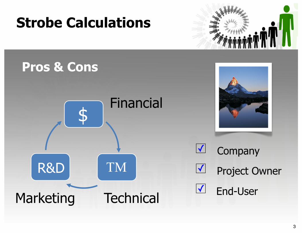
Company
Project Owner
End-User
☐✓
☐
☐
✓
✓
Financial
Technical
$
TM R&D
Marketing
Strobe Calculations
Pros & Cons
3
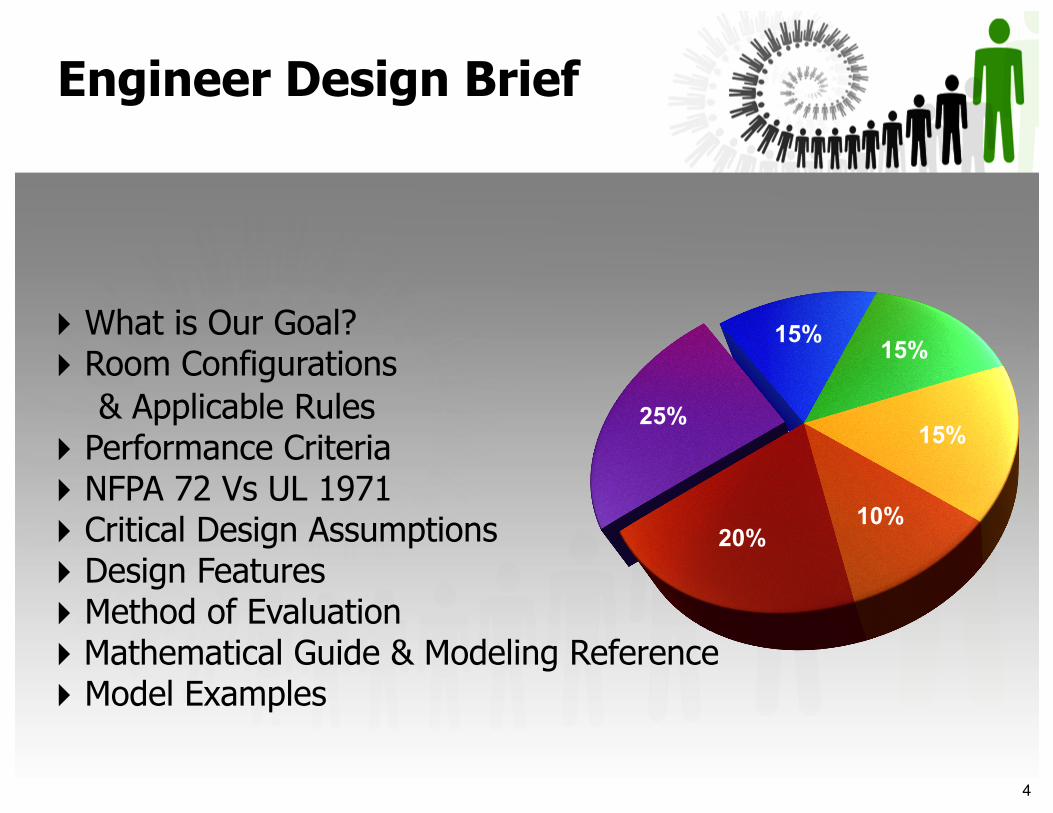
‣ What is Our Goal?‣ Room Configurations & Applicable Rules‣ Performance Criteria‣ NFPA 72 Vs UL 1971‣ Critical Design Assumptions‣ Design Features‣ Method of Evaluation ‣ Mathematical Guide & Modeling Reference‣ Model Examples
15% 15%
15%
10%20%
25%
Engineer Design Brief
4
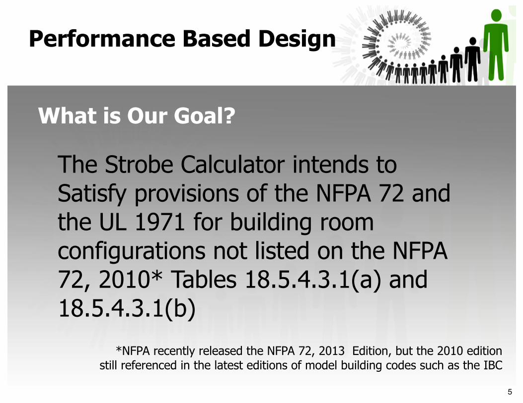
The Strobe Calculator intends to Satisfy provisions of the NFPA 72 and the UL 1971 for building room configurations not listed on the NFPA 72, 2010* Tables 18.5.4.3.1(a) and 18.5.4.3.1(b)
Performance Based Design
What is Our Goal?
*NFPA recently released the NFPA 72, 2013 Edition, but the 2010 edition still referenced in the latest editions of model building codes such as the IBC
5
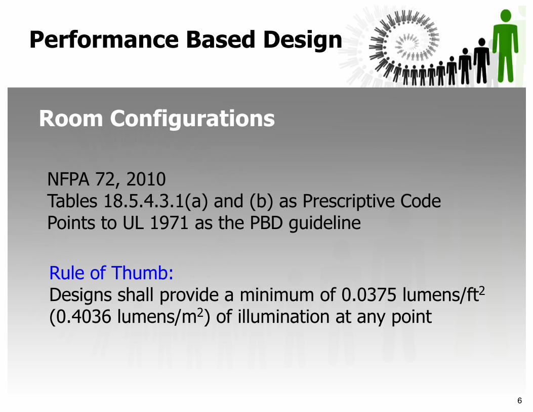
NFPA 72, 2010Tables 18.5.4.3.1(a) and (b) as Prescriptive Code Points to UL 1971 as the PBD guideline
Rule of Thumb:Designs shall provide a minimum of 0.0375 lumens/ft2 (0.4036 lumens/m2) of illumination at any point
Performance Based Design
Room Configurations
6
‣ The American with Disabilities Act, ADA
‣ The National Fire Alarm Code NFPA 72
‣ The American National Standards Institute, ANSI A117.1
‣ UL Standard 1971, Signaling Devices for the Hearing Impaired
Performance Based Design
Applicable Rules
7
40’
10’
22’
30cd Strobe
30cd
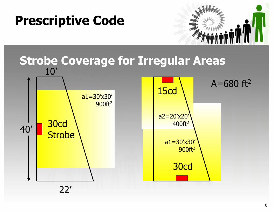
15cdA=680 ft2
a1=30’x30’900ft2
a1=30’x30’900ft2
a2=20’x20’400ft2
Prescriptive Code
Strobe Coverage for Irregular Areas
8

Minimum requirements are listed by ADAAG, NFPA 72 & UL 1971:
‣ 0.0375 lumens/ft2 (0.4036 lumens/m2) of illumination at any point and,
Performance Based Design
Performance Criteria
‣ Vertical, Horizontal and Polar Output as per UL 1971
9

UL 1971 Minimum Vertical Output, Wall Mounted
Angle
α (Deg)
Vertical
Output (%)
0 1005-30 9035 6540 4645 3450 2755 2260 1865 1670 1575 1380 1285 1290 12
90°
0°
α
Angular Derating Factor
Performance Criteria
10
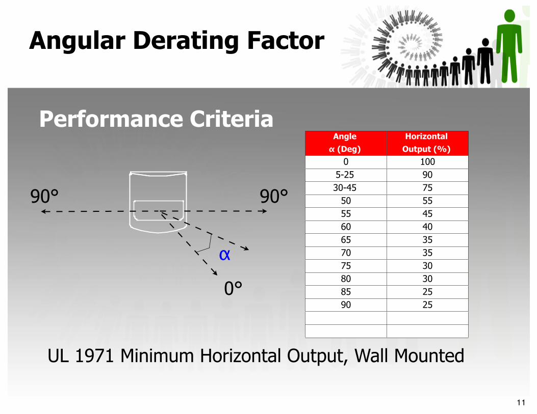
Angle
α (Deg)
Horizontal
Output (%)
0 1005-25 9030-45 75
50 5555 4560 4065 3570 3575 3080 3085 2590 25
0°
90°90°
α
UL 1971 Minimum Horizontal Output, Wall Mounted
Angular Derating Factor
Performance Criteria
11
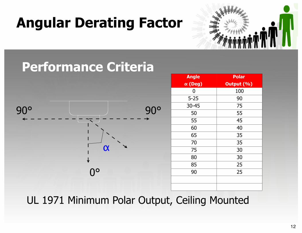
Angle
α (Deg)
Polar
Output (%)
0 1005-25 9030-45 75
50 5555 4560 4065 3570 3575 3080 3085 2590 250°
90°90°
α
UL 1971 Minimum Polar Output, Ceiling Mounted
Angular Derating Factor
Performance Criteria
12

MINIMUM REQUIRED LIGHT OUTPUT [cd] MINIMUM REQUIRED LIGHT OUTPUT [cd] MINIMUM REQUIRED LIGHT OUTPUT [cd] MINIMUM REQUIRED LIGHT OUTPUT [cd] MINIMUM REQUIRED LIGHT OUTPUT [cd] MINIMUM REQUIRED LIGHT OUTPUT [cd]
Maximum Room Size
Wall Mount as per NFPA (cd)
Wall Mount as per UL (cd)
Maximum Ceiling Height
Ceiling Mount as per NFPA (cd)
Ceiling Mount as per UL (cd)
20’x20’ 15 30 10’,20’,30’ 15, 30, 55 15, 30, 75
30’x30’ 34 75 10’,20’,30’ 30, 45, 75 75, 75, 75
40’x40’ 60 110 10’,20’,30’ 60, 75, 95 75, 75, 75
50’x50’ 94 177 10’,20’,30’ 95, 95, 95 110, 110, 110
60’x60’ 135 OVER 177 10’,20’,30’ 150, 150, 150 177, 177, 177
UL 1971 (PBD: Strobe Calculations)Vs
Performance Based Design
NFPA 72 (Prescriptive)
13
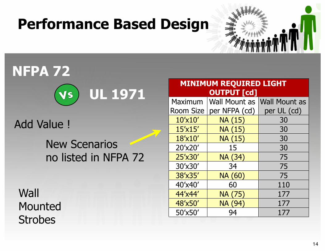
MINIMUM REQUIRED LIGHT OUTPUT [cd]
MINIMUM REQUIRED LIGHT OUTPUT [cd]
MINIMUM REQUIRED LIGHT OUTPUT [cd]
Maximum Room Size
Wall Mount as per NFPA (cd)
Wall Mount as per UL (cd)
10’x10’ NA (15) 3015’x15’ NA (15) 3018’x10’ NA (15) 3020’x20’ 15 3025’x30’ NA (34) 7530’x30’ 34 7538’x35’ NA (60) 7540’x40’ 60 11044’x44’ NA (75) 17748’x50’ NA (94) 17750’x50’ 94 177
WallMounted Strobes
New Scenarios no listed in NFPA 72
Add Value !
UL 1971
NFPA 72
Performance Based Design
Vs
14
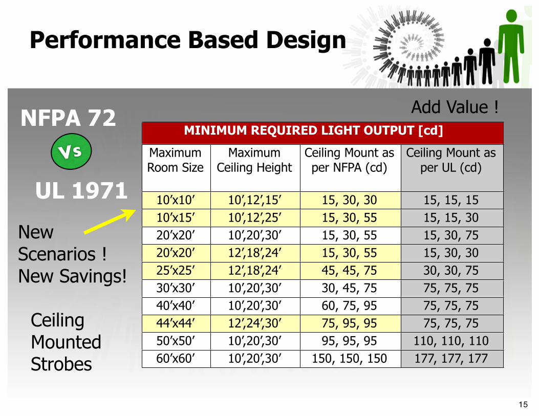
MINIMUM REQUIRED LIGHT OUTPUT [cd] MINIMUM REQUIRED LIGHT OUTPUT [cd] MINIMUM REQUIRED LIGHT OUTPUT [cd] MINIMUM REQUIRED LIGHT OUTPUT [cd]
Maximum Room Size
Maximum Ceiling Height
Ceiling Mount as per NFPA (cd)
Ceiling Mount as per UL (cd)
10’x10’ 10’,12’,15’ 15, 30, 30 15, 15, 1510’x15’ 10’,12’,25’ 15, 30, 55 15, 15, 3020’x20’ 10’,20’,30’ 15, 30, 55 15, 30, 7520’x20’ 12’,18’,24’ 15, 30, 55 15, 30, 3025’x25’ 12’,18’,24’ 45, 45, 75 30, 30, 7530’x30’ 10’,20’,30’ 30, 45, 75 75, 75, 7540’x40’ 10’,20’,30’ 60, 75, 95 75, 75, 7544’x44’ 12’,24’,30’ 75, 95, 95 75, 75, 7550’x50’ 10’,20’,30’ 95, 95, 95 110, 110, 11060’x60’ 10’,20’,30’ 150, 150, 150 177, 177, 177
New Scenarios ! New Savings!
Add Value !
CeilingMounted Strobes
UL 1971
NFPA 72
Performance Based Design
Vs
15
‣Distance from Strobe to most remote point
‣Inverse Square Law
‣Vertical, Horizontal & Polar distribution as per UL 1971
Add Value !
Performance Based Design
Critical Design Assumptions
16
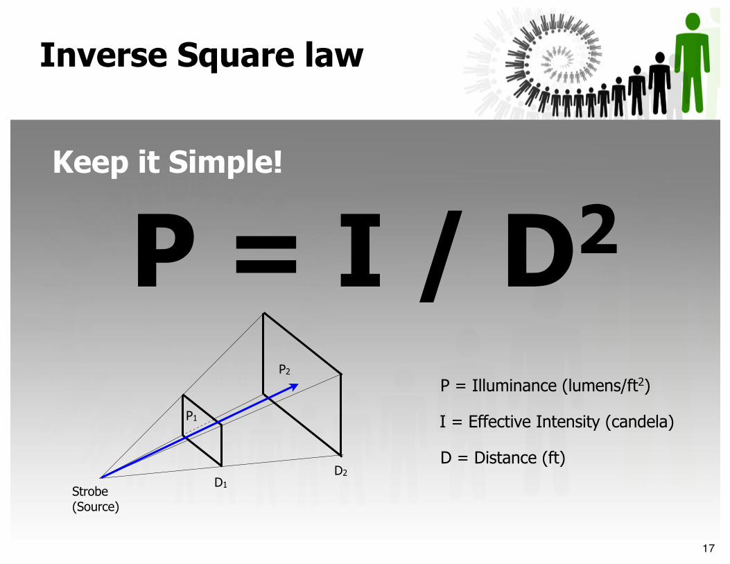
Keep it Simple!
P = I / D2 P = Illuminance (lumens/ft2)
I = Effective Intensity (candela)
D = Distance (ft)
Strobe(Source)
D1
D2
P1
P2
Inverse Square law
17
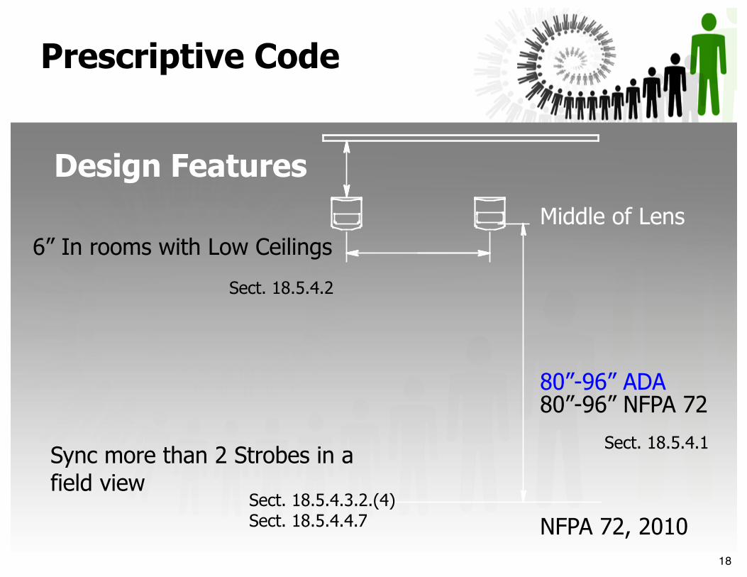
80”-96” ADA80”-96” NFPA 72
Sync more than 2 Strobes in a field view
6” In rooms with Low Ceilings
Sect. 18.5.4.1
Sect. 18.5.4.3.2.(4)Sect. 18.5.4.4.7
Sect. 18.5.4.2
Prescriptive Code
Design Features
Middle of Lens
NFPA 72, 201018
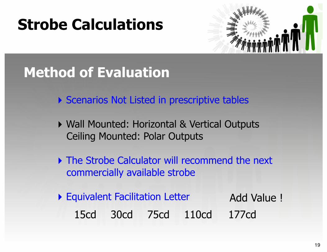
‣ Scenarios Not Listed in prescriptive tables
‣ Wall Mounted: Horizontal & Vertical Outputs Ceiling Mounted: Polar Outputs
‣ The Strobe Calculator will recommend the next commercially available strobe
‣ Equivalent Facilitation Letter
15cd 30cd 75cd 110cd 177cd
Add Value !
Strobe Calculations
Method of Evaluation
19
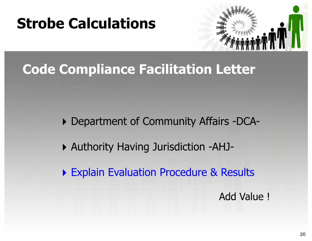
Add Value !
‣ Department of Community Affairs -DCA-
‣ Authority Having Jurisdiction -AHJ-
‣ Explain Evaluation Procedure & Results
Strobe Calculations
Code Compliance Facilitation Letter
20

Wall
x=Wide
y=Deep
h=Height
Strobe Location:
Ceiling
h =
Room Dimensions:
x =
y =
☐☐✓
12’
44’
44’
75cd
Recommended Strobe:
75cd
Performance Based Design
Model Interface
21
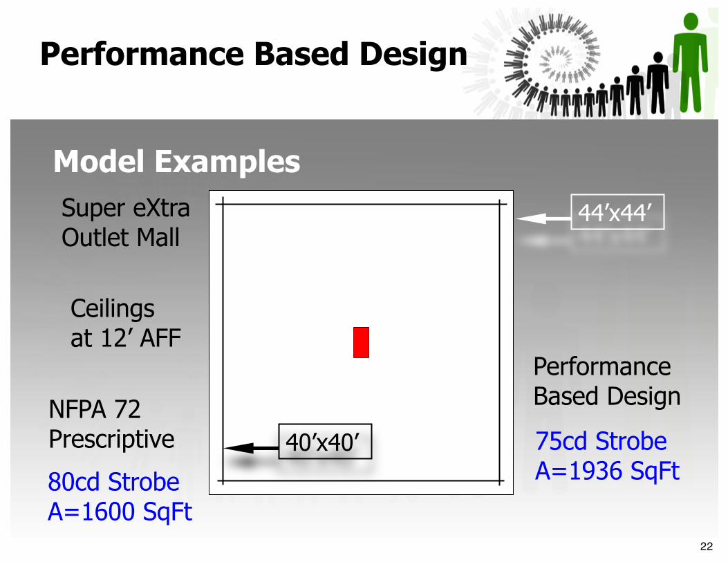
80cd StrobeA=1600 SqFt
Super eXtra Outlet Mall
NFPA 72Prescriptive 75cd Strobe
A=1936 SqFt
Performance Based Design
44’x44’
40’x40’
Ceilings at 12’ AFF
Performance Based Design
Model Examples
22
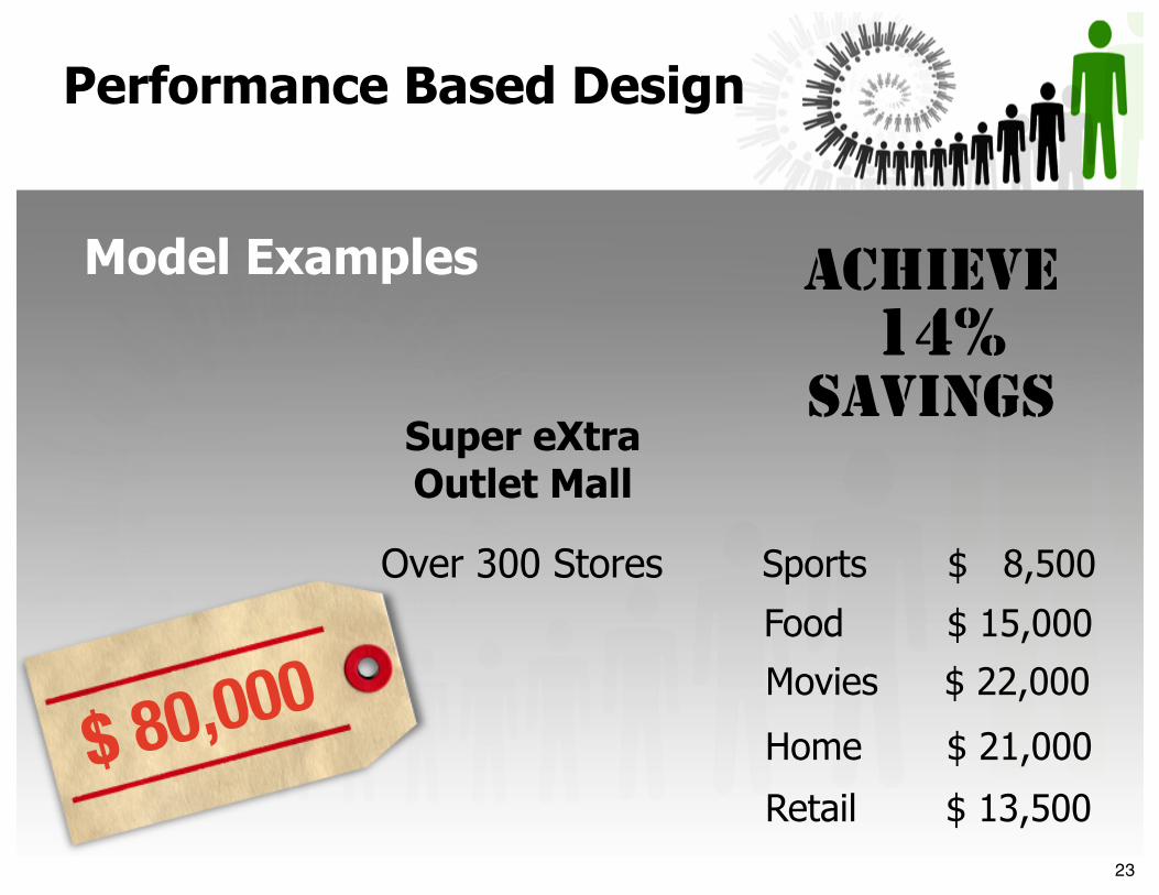
Sports
Food
Movies
Home
Retail
Over 300 Stores $ 8,500
$ 15,000
$ 22,000
$ 21,000
$ 13,500$ 80,000
ACHIEVE14%
SAVINGSSuper eXtra Outlet Mall
Performance Based Design
Model Examples
23

Equivalent Facilitation Letter
24

Performance Based Design
Model Examples
What about existing buildings?
‣ Existing Strobes not in compliance with proper coverage?
‣ Limited Wire, Circuit Runs and Power Supplies?
‣ Landmark or Sensitive Areas or Buildings?
‣ What would be the Maximum Coverage if...?
Add Value !
25
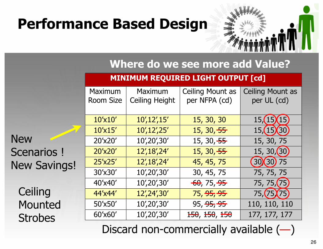
MINIMUM REQUIRED LIGHT OUTPUT [cd] MINIMUM REQUIRED LIGHT OUTPUT [cd] MINIMUM REQUIRED LIGHT OUTPUT [cd] MINIMUM REQUIRED LIGHT OUTPUT [cd]
Maximum Room Size
Maximum Ceiling Height
Ceiling Mount as per NFPA (cd)
Ceiling Mount as per UL (cd)
10’x10’ 10’,12’,15’ 15, 30, 30 15, 15, 1510’x15’ 10’,12’,25’ 15, 30, 55 15, 15, 3020’x20’ 10’,20’,30’ 15, 30, 55 15, 30, 7520’x20’ 12’,18’,24’ 15, 30, 55 15, 30, 3025’x25’ 12’,18’,24’ 45, 45, 75 30, 30, 7530’x30’ 10’,20’,30’ 30, 45, 75 75, 75, 7540’x40’ 10’,20’,30’ 60, 75, 95 75, 75, 7544’x44’ 12’,24’,30’ 75, 95, 95 75, 75, 7550’x50’ 10’,20’,30’ 95, 95, 95 110, 110, 11060’x60’ 10’,20’,30’ 150, 150, 150 177, 177, 177
New Scenarios ! New Savings!
Where do we see more add Value?
CeilingMounted Strobes
Performance Based Design
Discard non-commercially available ( )26

any?
27


References
ADAAG Visible Notification Sections 4.28.3 and 2,2 Equivalent FacilitationNFPA 72, National Fire Alarm Code, 1999, 2002, 2007, 2010 & 2013 Editions
UL Standard for Safety 1971, Signaling Devices for the Hearing ImpairedSFPE Handbook of Fire Protection Engineering, 3rd Edition
SFPE Engineering Guide to Performance-Based Fire Protection, 2nd Edition
Credits
Dr. James Milke. University of MarylandRolf Jensen & Associates. New York City
Thank You!
29