performance by design tm - eximcorp india pvt · pdf fileosb performance by design tm...
TRANSCRIPT

Performance by DesignTM
OSB IN WOOD FRAME CONSTRUCTIONU.S. EDITION 2005

OSB Performance by DesignTM
Oriented Strand Boardin Wood Frame Construction
U.S. Edition 2005

WAIVER OF RESPONSIBILITY
Every effort has been taken to ensure that the information published inthis manual is accurate and as complete as possible. The StructuralBoard Association does not, however, assume responsibility for errors oromissions in this publication, nor for any designs or specifications basedon it. It is the specifier’s and/or user’s responsibility to obtain thenecessary approvals and inspections from the local building officials.
© Copyright 2005 Structural Board Association
TM420 03M0705 ISBN 1-896479-01-4
Printed in Canada
ABOUT THIS MANUAL
This Manual has been developed to provide the designer, specifier, builderand home buyer with as complete a source of information as possible on thespecification and use of oriented strand board (OSB). Now in its fifteenth printing, it has been updated to reflect recent code changes, new standards,new information and new products. It also reflects the growth of the StructuralBoard Association as the leading voice of the OSB Industry.
ACKNOWLEDGEMENTSBA committed its technical resources and engaged the services of Quaile Engineering Ltd., andMarcom Group Inc. We would also like to acknowledge the participation of several industry reviewerswho ensured the completeness of this manual. Cover photos courtesy of Cloverdale Truss Co. Ltd.(Surrey, BC) and Weyerhaeuser Canada Ltd. (Edmonton, AB).
Performance by DesignTM is a registered trademark of the Structural Board Association.

1.0 Introduction1.1 Oriented Strand Board . . . . . . . . . . . . . . . . . . . . . . . . . . . . . . . . . . . . . . . . . . . . . . . . . . . . . . . . . . . .11.2 Research Program . . . . . . . . . . . . . . . . . . . . . . . . . . . . . . . . . . . . . . . . . . . . . . . . . . . . . . . . . . . . . . .1
2.0 Manufacturing Process2.1 Basic Steps . . . . . . . . . . . . . . . . . . . . . . . . . . . . . . . . . . . . . . . . . . . . . . . . . . . . . . . . . . . . . . . . . . . . .22.2 Performance by DesignTM . . . . . . . . . . . . . . . . . . . . . . . . . . . . . . . . . . . . . . . . . . . . . . . . . . . . . . . . . .22.3 Quality Assurance . . . . . . . . . . . . . . . . . . . . . . . . . . . . . . . . . . . . . . . . . . . . . . . . . . . . . . . . . . . . . . . .22.4 OSB and the Environment . . . . . . . . . . . . . . . . . . . . . . . . . . . . . . . . . . . . . . . . . . . . . . . . . . . . . . . . .3
3.0 OSB Products3.1 Panel Sizes and Thicknesses . . . . . . . . . . . . . . . . . . . . . . . . . . . . . . . . . . . . . . . . . . . . . . . . . . . . . . .43.2 OSB and the Building Codes . . . . . . . . . . . . . . . . . . . . . . . . . . . . . . . . . . . . . . . . . . . . . . . . . . . . . . .43.3 PS 2 Grades and Classifications . . . . . . . . . . . . . . . . . . . . . . . . . . . . . . . . . . . . . . . . . . . . . . . . . . . . . . . . .53.4 Panel Marking . . . . . . . . . . . . . . . . . . . . . . . . . . . . . . . . . . . . . . . . . . . . . . . . . . . . . . . . . . . . . . . . . . .5
4.0 Properties4.1 Physical and Mechanical . . . . . . . . . . . . . . . . . . . . . . . . . . . . . . . . . . . . . . . . . . . . . . . . . . . . . . . . . .64.2 Other Properties . . . . . . . . . . . . . . . . . . . . . . . . . . . . . . . . . . . . . . . . . . . . . . . . . . . . . . . . . . . . . . . . .7
5.0 Residential and Low Rise Commercial Installation5.1 Span Ratings . . . . . . . . . . . . . . . . . . . . . . . . . . . . . . . . . . . . . . . . . . . . . . . . . . . . . . . . . . . . . . . . . . .95.2 Floor Sheathing . . . . . . . . . . . . . . . . . . . . . . . . . . . . . . . . . . . . . . . . . . . . . . . . . . . . . . . . . . . . . . . . .105.2.1 Fastening for Floor Sheathing . . . . . . . . . . . . . . . . . . . . . . . . . . . . . . . . . . . . . . . . . . . . . . . . . . . . .115.2.2 Installing Finished Flooring . . . . . . . . . . . . . . . . . . . . . . . . . . . . . . . . . . . . . . . . . . . . . . . . . . . . . . . .115.2.3 Concrete Topping . . . . . . . . . . . . . . . . . . . . . . . . . . . . . . . . . . . . . . . . . . . . . . . . . . . . . . . . . . . . . . .145.2.4 Hardwood Floors . . . . . . . . . . . . . . . . . . . . . . . . . . . . . . . . . . . . . . . . . . . . . . . . . . . . . . . . . . . . . . . .145.2.5 Ceramic Tile . . . . . . . . . . . . . . . . . . . . . . . . . . . . . . . . . . . . . . . . . . . . . . . . . . . . . . . . . . . . . . . . . . .155.2.6 Floor Vibration . . . . . . . . . . . . . . . . . . . . . . . . . . . . . . . . . . . . . . . . . . . . . . . . . . . . . . . . . . . . . . . . . .155.3 Floor Underlayment . . . . . . . . . . . . . . . . . . . . . . . . . . . . . . . . . . . . . . . . . . . . . . . . . . . . . . . . . . . . .165.4 Roof Sheathing . . . . . . . . . . . . . . . . . . . . . . . . . . . . . . . . . . . . . . . . . . . . . . . . . . . . . . . . . . . . . . . . .175.4.1 High Wind Areas . . . . . . . . . . . . . . . . . . . . . . . . . . . . . . . . . . . . . . . . . . . . . . . . . . . . . . . . . . . . . . . . . . . . . . . .185.4.2 Ventilation of Attic and Roof Spaces . . . . . . . . . . . . . . . . . . . . . . . . . . . . . . . . . . . . . . . . . . . . . . . . . . . . . . . .185.4.3 Prevention of Ice Damming . . . . . . . . . . . . . . . . . . . . . . . . . . . . . . . . . . . . . . . . . . . . . . . . . . . . . . .185.5 Wall Sheathing . . . . . . . . . . . . . . . . . . . . . . . . . . . . . . . . . . . . . . . . . . . . . . . . . . . . . . . . . . . . . . . . .195.6 Maximum Loads for OSB Panels . . . . . . . . . . . . . . . . . . . . . . . . . . . . . . . . . . . . . . . . . . . . . . . . . . .205.7 Moisture During Construction . . . . . . . . . . . . . . . . . . . . . . . . . . . . . . . . . . . . . . . . . . . . . . . . . . . . . .205.8 Detailing and Good Construction Practices . . . . . . . . . . . . . . . . . . . . . . . . . . . . . . . . . . . . . . . . . . .205.9 Shipping, Handling and Storage . . . . . . . . . . . . . . . . . . . . . . . . . . . . . . . . . . . . . . . . . . . . . . . . . . . .20
6.0 Other Uses for OSB6.1 Structural Insulated Panels . . . . . . . . . . . . . . . . . . . . . . . . . . . . . . . . . . . . . . . . . . . . . . . . . . . . . . . .216.2 Wood I-Joists . . . . . . . . . . . . . . . . . . . . . . . . . . . . . . . . . . . . . . . . . . . . . . . . . . . . . . . . . . . . . . . . . .216.2.1 Engineered Floor Systems . . . . . . . . . . . . . . . . . . . . . . . . . . . . . . . . . . . . . . . . . . . . . . . . . . . . . . . .216.3 Renovation . . . . . . . . . . . . . . . . . . . . . . . . . . . . . . . . . . . . . . . . . . . . . . . . . . . . . . . . . . . . . . . . . . . .216.4 Industrial Applications . . . . . . . . . . . . . . . . . . . . . . . . . . . . . . . . . . . . . . . . . . . . . . . . . . . . . . . . . . . .216.5 Horizontal Diaphragms and Shearwalls . . . . . . . . . . . . . . . . . . . . . . . . . . . . . . . . . . . . . . . . . . . . . .226.6 Engineering Design . . . . . . . . . . . . . . . . . . . . . . . . . . . . . . . . . . . . . . . . . . . . . . . . . . . . . . . . . . . . . .226.7 OSB Panels over Metal Framing . . . . . . . . . . . . . . . . . . . . . . . . . . . . . . . . . . . . . . . . . . . . . . . . . . .22
TABLE OF CONTENTS
i

i i
Figure 1 OSB Manufacturing Process . . . . . . . . . . . . . . . . . . . . . . . . . . . . . . . . . . . . . . . . . . . . . . . . . . . . . . .12
Figure 2 OSB Lay-up . . . . . . . . . . . . . . . . . . . . . . . . . . . . . . . . . . . . . . . . . . . . . . . . . . . . . . . . . . . . . . . . . . . . .2
Figure 3 Examples of Certification Marks . . . . . . . . . . . . . . . . . . . . . . . . . . . . . . . . . . . . . . . . . . . . . . . . . . . . . .5
Figure 4 Floor Sheathing Installation . . . . . . . . . . . . . . . . . . . . . . . . . . . . . . . . . . . . . . . . . . . . . . . . . . . . . . . .10
Figure 5 Floor Underlayment Installation . . . . . . . . . . . . . . . . . . . . . . . . . . . . . . . . . . . . . . . . . . . . . . . . . . . . .16
Figure 6 Roof Sheathing Installation . . . . . . . . . . . . . . . . . . . . . . . . . . . . . . . . . . . . . . . . . . . . . . . . . . . . . . . . .17
Figure 7 Wall Sheathing Installation . . . . . . . . . . . . . . . . . . . . . . . . . . . . . . . . . . . . . . . . . . . . . . . . . . . . . . . . .19
Figure 8 Typical Structural Insulated Panel . . . . . . . . . . . . . . . . . . . . . . . . . . . . . . . . . . . . . . . . . . . . . . . . . . .21
Table 1 Basic Properties of OSB . . . . . . . . . . . . . . . . . . . . . . . . . . . . . . . . . . . . . . . . . . . . . . . . . . . . . . . . . . . .6
Table 2 Physical Properties of OSB . . . . . . . . . . . . . . . . . . . . . . . . . . . . . . . . . . . . . . . . . . . . . . . . . . . . . . . . .8
Table 3 Minimum Nail Resistance for Panels Meeting PS 2 . . . . . . . . . . . . . . . . . . . . . . . . . . . . . . . . . . . . . . .8
Table 4 Fastening Schedule for OSB Sheathing . . . . . . . . . . . . . . . . . . . . . . . . . . . . . . . . . . . . . . . . . . . . . . .11
Table 5 Nail Weight, Length and Gage . . . . . . . . . . . . . . . . . . . . . . . . . . . . . . . . . . . . . . . . . . . . . . . . . . . . . .14
Table 6 Recommended Floor Sheathing for Hardwood Flooring . . . . . . . . . . . . . . . . . . . . . . . . . . . . . . . . . .14
Table 7 Recommended Floor Sheathing Systems for Ceramic Tile Flooring . . . . . . . . . . . . . . . . . . . . . . . . .15
Table 8 Maximum Allowable Loads for SBA OSB Rated Roof Sheathing . . . . . . . . . . . . . . . . . . . . . . . . . . .20
Table 9 Allowable Shear Forces for OSB Shearwalls . . . . . . . . . . . . . . . . . . . . . . . . . . . . . . . . . . . . . . . . . . .23
Table 10 Allowable Shear Forces for OSB Horizontal Diaphragms . . . . . . . . . . . . . . . . . . . . . . . . . . . . . . . . .24
Appendix A Glossary of Terms . . . . . . . . . . . . . . . . . . . . . . . . . . . . . . . . . . . . . . . . . . . . . . . . . . . . . . . . . . . . . . .25
Appendix B SBA Member Plant Locations . . . . . . . . . . . . . . . . . . . . . . . . . . . . . . . . . . . . . . . . . . . . . . . . . . . . . . .26
SBA Member Companies . . . . . . . . . . . . . . . . . . . . . . . . . . . . . . . . . . . . . . . . . . . . . . . . . . . . . . . . . .27
Associate, Allied and Research Members . . . . . . . . . . . . . . . . . . . . . . . . . . . . . . . . . . . . . . . . . . . . .28

Oriented Strand Board (OSB) is a structural panelsuitable for a wide range of construction and industrial applications. It is a mat-formed panelmade of strands sliced in the long direction fromsmall diameter, fast growing round wood logs andbonded with an exterior-type binder under heat and pressure.
OSB’s predecessor random waferboard has been commercially available since 1962. OSBbecame available in 1981 and has now replaced waferboard. However, waferboard rated sheathingpanels that meet U.S. codes are still available from one manufacturer in Canada. OSB as a performance based structural-use panel is recognized by all the major U.S. Model Code agencies through the adoption of the USDepartment of Commerce Voluntary PerformanceStandard PS 2 “Performance Standard for WoodBased Structural Use Panels”. OSB and waferboard are recognized by the National Building Code of Canada.
The OSB industry is well established and stillgrowing. To the end of 2004 the North Americanindustry had grown to 64 mills (40 U.S., 24Canadian) with a combined productive capacity of27 billion square feet (3/8" basis). Additional millsare under construction and in the planning stage inthe US, Canada and offshore. It is anticipated thatby 2007 there will be over 80 mills worldwide.
Over the years the SBA has been a major participantin the direction, coordination and funding of a market driven research and development program.Its purpose is to enhance the OSB productsmanufactured by its members, as well as to optimizethe manufacturing process. This program, conductedby an alliance of reputed research organizations anduniversities in the U.S. and Canada, led to severalachievements including but not limited to:optimization of log yard management and pressingoperations, development of OSB products withimproved physical and mechanical properties, OSBproduct stewardship, process modeling, anddevelopment of OSB engineering properties.
1
1.0 INTRODUCTION
1.1 Oriented Strand Board
1.2 Research Program

2
Figure 1 illustrates the typical sequence in themanufacturing of OSB (see center spread).OSB is made from freshly harvested aspen poplar,southern yellow pine or other mixed hardwood andsoftwood logs. The logs are debarked and cut toshorter lengths before being processed in thestrander. The fines and bark become fuel for themill’s energy system.
The strander slices the logs into strands along the direction of the grain. Strand dimensions arepredetermined for the process and have a uniformthickness. The majority of Association mills use acombination of strands ranging in length from 3-1/2"to 6" and approximately 1" wide.
The strands are then dried and sorted. Beforeforming, the strands are mixed with wax and awaterproof exterior-type binder (generally phenolicor isocyanate resin binder).These waterproof andboil-proof resin binders will provide the panel withinternal strength, rigidity and moisture resistance.
During forming the strands are oriented in layers.The strands on the panel surface are generallyaligned in the long direction of the panel for superiorbending strength and stiffness in this direction (seeFigure 2). The two or three inner layers are usuallycross-aligned to the surface layer like plywood.
After forming, the mat of strands is pressed at ahigh temperature and pressure to form a rigid,dense structural panel. OSB has considerablebending strength that comes from the uninterruptedfibre, interweaving of the long strands andorientation of strands in the surface layers.
The panels are then cooled, cut to size, gradestamped, edge coated and stacked in bundles forshipping.
Oriented Strand Board structural wood panels areoften designed in the manufacturing process tomeet specific end uses required by the customer.This flexibility in manufacturing provides superiorperformance with economical cost to give excellentvalue to the end user.
The quality of OSB is the responsibility of theindividual producer. Each SBA mill has a program of in-plant quality control to ensure the finishedproduct meets or exceeds the grade required in theapplicable standard and the mill specification. Thirdparty quality assurance and audit programs back upthe mill programs.
The SBA suggests that its producer members adopta “Total Quality” concept. This starts with the cuttingof trees in the forest to the shipping of finishedproduct from the mill to the customer’s satisfaction.State-of-the-art computer process controlequipment, which is uniquely designed for eachplant, greatly helps the implementation of in-millquality control by monitoring and adjusting theprocess variables on a continuous basis. Plantquality control staff oversee the process monitoring,paying particular attention to selection of logs byspecies, size and moisture content; strand geometryand thickness; strand moisture content after drying;
2.0 MANUFACTURING PROCESS
2.1 Basic Steps
Figure 2 OSB Lay-up
(A) OSB with aligned faceand random core
(B) OSB with aligned faceand oriented core
2.2 Performance by DesignTM
2.3 Quality Assurance

3
consistent blending of strands with resin binder andwax; uniform forming of the mat entering the press;the press temperature, pressure, closing speed,density and thickness control.
Quality control personnel regularly inspect panelfaces, edges, dimensions after trimming and thephysical appearance of the finished panel. Theyalso undertake physical testing of the panelsaccording to standard test procedures as necessaryto verify that production conforms to the applicablestandard and mill specification. Besides companyprocess and quality control, manufacturers contractwith an independent inspection and certificationagency such as APA, TECO, or PSI/PTL forindependent appraisal and verification of quality.
Oriented Strand Board is generally manufacturedfrom aspen poplar in the northern part of NorthAmerica and southern yellow pine in the South.However, other hardwood and softwood species or combinations may also be used. Aspen poplar andnorthern hardwoods are harvested from naturallyregenerated self-sustaining stands. Southern yellowpine is harvested from managed private stands and includes thinnings. The manufacturing processuses 90% of the log and modern mills typicallyconvert the remaining bark, saw trim, and sawdust into energy.
Modern mills are scientifically designed to meet orexceed the strict quality standard for air emissionsby using collectors, precipitators, scrubbers orregenerative thermal oxidation units to removeparticulate and volatile organic compounds from the discharge gases released into the atmosphere.Where log soaking ponds are used, the pond wateris filtered, the ponds cleaned regularly and thesludge burned as fuel. The mills are designed to beself sufficient in terms of heat energy with all bark,screenings, sawdust and panel trim recycled as fuel for the dryer and the press heating system.
Like construction plywood, OSB panels are bondedunder heat and pressure with phenol formaldehydeor isocyanate binders that become durable,insoluble heat-resistant polymers that resist age,moisture and chemical degradation. Regular testsconfirm formaldehyde emissions from phenolic-bonded OSB panels are nonexistent or negligible.Due to excellent test performance, OSB panels are
exempted from the HUD Manufactured HomesConstruction and Safety Standard (MHCSS) ruleregarding formaldehyde emissions from panel products.
SBA oriented strand board panels are registered inaccordance with the New York State Smoke toxicityregulations. Contact SBA for specific details on thisrequirement.
SBA also provides a generic Material Safety DataSheet (MSDS) for OSB and waferboard, and othertechnical information on the binder system. Tocomply with Occupational Safety and HealthAdministration (OSHA) manufacturers are alsorequired to issue statements about wood dust.Consult with OSB manufacturers for wood dustlabels or MSDS.2.4 OSB and the Environment

4
3.0 OSB PRODUCTS
Performance OSB panels are specificallyengineered for floor, roof, and wall sheathingpurposes in wood frame construction. Panels areavailable in nominal 4'x8' sheets (1220x2440 mm)or cut to size dimensions. For industrial applicationssizes up to 8'x24' (2440x7320 mm) and larger areavailable by special order. Some new millsmanufacture master panels up to 12' (3660 mm)wide or other custom sizes from continuouspresses.
The most common thicknesses are 1/4", 3/8", 7/16",15/32", 19/32", 23/32". Other panel thicknessesincluding 7/8", 1-1/8" and 1-1/4" are available onspecial order. Panels 19/32" and thicker aremanufactured either square-edged or tongue andgrooved on the long edge. Most mills producepanels with textured surface treatments forimproved traction on sloping roofs. Regular panelsare either unsanded or rough (touch) sanded,however the product may be ordered smoothsanded on one or both sides for industrial ordecorative uses.
SBA members’ OSB production is chiefly intendedfor use in both the United States and Canada. As aresult OSB panels are manufactured to meet U.S.Department of Commerce Voluntary PerformanceStandard PS 2 “Performance Standard for WoodBased Structural Use Panels” and/or Canadian performance standard CSA O325 “ConstructionSheathing”. In Canada panels may also be produced to meet CSA Standard O437 “OSB and Waferboard”.
The voluntary standard PS 2 was a joint development of the U.S. and Canadian wood panelindustry to harmonize the performance standardsunder the U.S./Canada Free Trade Agreement.
The standard was promulgated by the U.S.Congress in August 1992. A second edition waspublished in 2004. PS 2 covers OSB, plywood, andcomposite panels and was initially recognized bythe National Building Code (BOCA), the One andTwo Family Dwelling Code (CABO), the StandardBuilding Code (SBCCI), the Uniform Building Code(ICBO) and more recently by the InternationalBuilding Code and the International ResidentialCode (ICC). These new model I-codes recognizethe following major uses of PS 2 certified OSBpanels:
- combined subfloor underlayment (single layer floors)
- roof sheathing
- soffits
- subfloors
- underlayment
- wall sheathing
Panels qualified to PS 2 are often called“Performance Based” or “Rated”. Several certification agencies may carry out this workincluding APA, TECO or PSI/PTL.
Prior to the adoption of PS 2, performance basedOSB panels were recognized as structural usepanels by the National Evaluation Service of CABOas acceptable alternates to panels specified in thecodes. The acceptance was covered by NationalEvaluation Report (NER) No. 108 (APA) and No. 133 (TECO). SBA’s NER No. 322 was withdrawn after the code acceptance of PS 2.
HUD’s materials bulletin (UM-40C) gives genericrecognition to performance rated panels certifiedby a certification agency meeting its requirements.APA, TECO and PSI have been accepted by HUDas certification agencies.
3.1 Panel sizes and thicknesses
The standard thicknesses of OSB are as follows:
English (in.) 1/4 5/16 3/8 7/16 15/32 1/2 19/32 5/8 23/32 3/4
Metric (mm) 6.0 7.5 9.5 11.0 12.0 12.5 15.0 15.5 18.0 18.5
3.2 OSB and the Building Codes

5
Figure 3 Examples of Certification Marks
PS 2 PRP-133HUD-UM-40C
EXPOSURE 1SHEATHING SPAN 3/8" 24/0 RATING
SIZED FOR SPACING
MANUFACTURER'SNAME AND ADDRESS
MILL NO.
CONSTRUCTION SHEATHING2R24 / W24
9.5 mmCSA 0325
STRENGTH AXISTHIS DIRECTION
Structural use panels evaluated according to PS 2 are assigned structural grades and glue bond classifications.
Structural Grades
PS 2 specifies performance tests for concentratedand uniform static loads under wet and dry conditions. Impact tests are also specified as wellas racking performance and fastener holding capability. Three grades of sheathing are specifiedas follows:
• Sheathing
For use in construction applications as coveringmaterial for roofs, subfloors, and walls.
• Structural 1 Sheathing
This is essentially a Sheathing Grade panel that hasmet additional requirements for cross-panel strengthand stiffness as well requirements for racking shear.These additional requirements are for use in panelized roof systems, diaphragms and shearwalls.
• Single Floor
For use as a combination subfloor and underlayment. The static load and deflection performance requirements for single floor panelsare more stringent than for Sheathing Grade.
Glue Bond Classification
PS 2 classifies structural use panels into threeexposure categories, which depend on raw materialcomposition and adhesive bond durability. Most
OSB panels are classified as Exposure 1 . Thesepanels are suitable for uses not permanentlyexposed to the weather and are intended to resisteffects of moisture on their structural performancedue to construction delays, or other conditions ofsimilar severity. The bond classification is related tothe moisture resistance of the glue bond underintended use, but is not related to the physical (ie. erosion, U.V. light) or biological (ie. mold, decay,insect) resistance of the panel.
SBA members clearly mark all certified boardsintended for use in construction with an approvedagency certification mark (see Figure 3 forexamples).
The certification agency stamp will show the following information for panel identification:
- Span rating (i.e. 24/16)- Nominal thickness (i.e. 7/16")- Bond classification (i.e. Exposure 1)- Grade (i.e. Sheathing)- Manufacturer’s name or mill number- Certification organization logo and
performance standard (i.e. TECO PRP133)- PS 2 symbol signifying conformance
to the performance standard- Direction of the surface strand alignment.
Canadian standard information may also beincluded as part of or on a separate stamp.(see Figure 3 for examples, or refer to our TechnicalBulletin, TB107, Marking of OSB, available onwww.osbguide.com)
3.3 PS 2 Grades and Classifications
3.4 Panel Marking

6
4.0 PROPERTIES
Property PS 2 1 CSA O437(Grade O-2)
Thickness tolerancepanels ≤ 13/16" (20.5 mm) ± 1/32" (0.8 mm) ± 0.03" (± 0.75 mm)panels > 13/16" (20.5 mm) ± 5% of thickness ± 0.03" (± 0.75 mm)
Size tolerance (length and width)(maximum deviation from specified size) +0, -1/8" (+0 mm, - 3.2 mm) +0, -5/32" (+0 mm, - 4 mm)
Squareness tolerance(maximum deviation from square) 1/64 in/ft of diagonal 5/32"
(1.3 mm/m) (4 mm)
Straightness tolerance(maximum deviation from straight line) 1/16" corner to corner 1/16" corner to corner
(1.6 mm) (1.6 mm)
Minimum modulus of rupture 2
parallel N/A (not applicable) 4200 psi (29.0 MPa)perpendicular N/A 1800 psi (12.4 MPa)
Minimum modulus of elasticity 2
parallel N/A 800,000 psi (5500 MPa) perpendicular N/A 225,000 psi (1500 MPa)
Minimum internal bond 2 N/A 50 psi (0.345 MPa)
Maximum linear expansionoven dry to saturated N/A 0.35% parallel
N/A 0.50% perpendicular
one sided wetting 0.30% along major axis N/A (or 50% to 90% relative humidity R.H.) 0.35% across major axis N/A
50% R.H. to vacuum pressure soak 0.50% N/A
Maximum thickness swell 25% (one sided wetting 15% for 1/2" thick or lessor R.H. exposure) 10% for greater than 1/2"(Single Floor only) (24 hour soak)
Bond classification(minimum modulus of rupture)2
single cycle test see Table 6 of PS 2 N/Asix-cycle test 50 % retention N/A2 hour boil - parallel N/A 2100 psi (14.5 MPa)
- perpendicular N/A 900 psi (6.2 MPa)
Minimum lateral nail resistance 2 see Table 3 400t lb (70t N)where t = thickness, in. (mm)
The physical and mechanical properties of performance based panels established by the certification agency are proprietary except the spanrating. As a result the properties can vary from mill tomill. Some mills produce panels that have at least theminimum properties outlined in CSA
Standard O437. Basic properties of grade O-2properties are summarized in Table 1 along with theproperties specified in PS 2. Property values ofactual production panels are maintained by SBAmembers at levels superior to those shown in the table.
Table 1 Basic Properties of OSB
Notes:1 PS 2 ( or CSA O325 in Canada ) panels are performance rated for each application (see Section 5.1)2 Strength and stiffness values are average ultimate test values, not working stresses for design purposes.
4.1 Physical and Mechanical

7
Other properties of OSB may be summarized as follows:
WorkabilityOSB is easy to saw, drill, nail, plane, file or
sand. It contains wood, fully cured waterproof and boilproof resin adhesive and a small amount of wax. Usenormal carpentry tools, but carbide tipped blades arerecommended for prolonged use. Wear appropriatesafety protection and follow safe working procedures.As wood dust has been designated as a potential carcinogen, avoid overexposure to airborne dustparticles and keep work areas free of dust build-up.
As full-size panels have a factory applied edgecoating, job cut panels likely to be exposed to theweather should have uncoated edges protected by afield coat of paint or by sheathing paper to reducemoisture pick-up.
NailabilityThe many interleaved layers create panels with
good nail holding properties. Nails can be driven asclose as 1/4" from the panel edges without risk ofsplitting or breaking out. However, the Associationrecommends an edge distance of 3/8" for structuralapplications. Extensive tests undertaken by researchestablishments show fastener performance is similarfor all structural wood panels. In addition PS 2 specifies minimum nail holding capability for performance based OSB. When using power actuated nailers, wear eye protection, follow safeworking procedures, and do not overdrive nails.
GluabilityOSB may be glued with any adhesive
recommended for wood. For strong bonds, lightlysand the surfaces in the areas to be glued.
PaintabilityOSB may be finished with any good quality paint
system recommended for wood. For best results, thesurface must be primed or sealed before painting.
For exterior applications, the best finish is a goodquality exterior wood paint system (primer and topcoat) applied according to the paint manufacturer’sdirections. Solid color paints provide the best weatherprotection for the panel surface and the strands showa pleasing texture. A top quality acrylic latex exteriorpaint and companion primer specifically designatedby the manufacturer as ‘stain blocking’ or ‘stain resistant’ are recommended. OSB also takes all kindsof stain finishes as well. However, stains do not offeras much surface protection from the weather as
paints and the lifting of an occasional strand mayoccur. Stains are therefore more suited to fences,summer cottages and other applications that accept amore rustic appearance.
Sanded panels present a marble-like appearanceand they are less textured than unsanded panels.As varnishes, stains and paints penetrate the sandedpanels more quickly than the unsanded, two coats ofprimer or sealer are recommended before applicationof the finish system. When applying paint or varnish,sand the surfaces lightly between coats; do not sandstained surfaces.
WeightThe approximate weight of OSB panels is shown
in Table 2. These values are based on a density of 40 pcf. Density may vary depending on the manufacturer, and moisture conditions at the time ofshipment.
Thermal ResistanceThe thermal coefficient of resistivity “R” of a
material is a measure of the resistance it offers to thepassage of conducted heat at a steady rate. It is proportional to the density and thickness of thematerial. Table 2 provides R values for various thicknesses of OSB.
PermeabilityThe permeability of a wood panel is the rate that
moisture passes through the panel under stated conditions of moisture vapor pressure. It is inversely proportional to the density, degree of orientation and thickness of the panel. Values for OSBpanels are given in Table 2.
Fire PerformanceOSB has been tested to determine fire endurance
and flame spread ratings by both SBA and APA.These tests have been undertaken by third partyagencies using recognized fire test laboratories.The test results show that OSB panels, like plywood, may be used as exterior sheathing on outside wallsrequired to have a fire rating. However, code authorities may require that stud spaces be filledwith non-combustible insulation such as rock woolwhen structural wood panels are used on these walls.Structural wood panels are permitted to be installedbetween the framing and the fire-resistive covering inwalls provided the length of the fastener used toattach the fire protection is increased by an amount atleast equal to the thickness of the wood panel.
4.2 Other Properties

8
Flame spread rating tests have also beenconducted on OSB panels, and it has been determined that an uncoated OSB panel and apanel having one coat of acrylic latex interiorhousehold paint will meet the requirement of a 150 flame spread rating. (see Table 2)
Moisture PerformanceOSB like all wood products reacts to changes in
moisture and humidity conditions. OSB is required by
North American Standards to maintain its strengthand stiffness performance under normal humidity conditions, also referred to as “standard conditions”,which are represented by a temperature of 68degrees fahrenheit and 65 percent relative humidity.This condition is typical of protected construction.In addition, OSB is required to maintain its strengthand stiffness performance when exposed to weatherduring long construction delays.
Nominal Weight Thermal Vapor Flame Smokepanel (psf) resistance R permeance Spread Developed
thickness (in) (ft 2.hr. °F/Btu) (perms) Rating 1 Index 1
3/8 1.25 0.45 2.55 148 137
7/16 1.46 0.51 1.95 148 137
1/2 1.67 0.62 1.55 148 137
5/8 2.08 0.74 1.1 148 137
3/4 2.5 0.91 1.1 2 148 137
Table 2 Physical Properties of OSB
Table 3 Minimum Nail Resistance for Panels Meeting PS 2 1, 2
Notes:1 These numbers are average test values obtained by APA, The Engineered Wood Association on several thicknesses of OSB.
All test results fell in the range of Class 3 or C, depending on the building code, for interior finish material.2 Panel thicknesses greater than 5/8" were not tested, but can be assumed to provide a permeability resistance equal to or better
than that of 5/8" panels. Vapor permeance values are given for 50% relative humidity (R.H.), and increase slightly withincreasing R.H.
Loading Application Minimum ultimate load (lb) 3
Dry Wet/Dry
Lateral roof and wall sheathing 120 90
subfloors and single floors 210 160
Withdrawal all sheathing 20 15
Notes:1 Nails are 6d ( 2" or 51 mm) common smooth-shank nails for sheathing up to 1/2" (12.5 mm) thick, 8d (2 1/2" or 63 mm)
for thicker panels.2 Comparison studies (University of Illinois) have shown the equivalent performance of OSB and plywood in lateral and
withdrawal resistance of nails and staples.3 These values are not for design purposes.
9
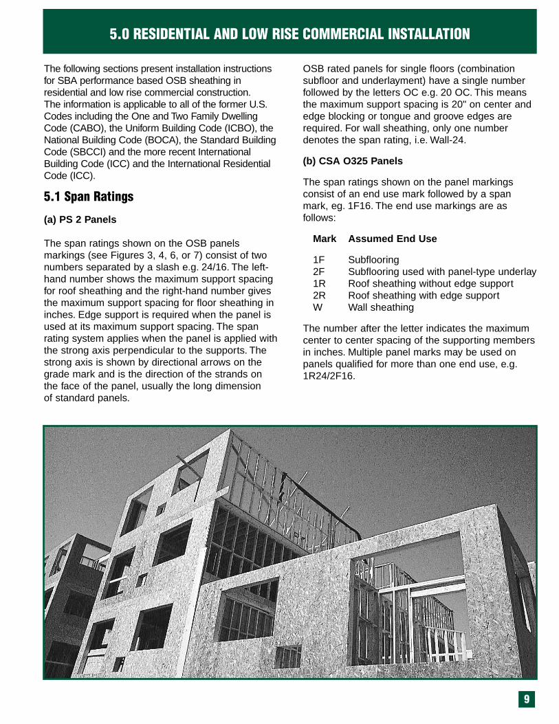
The following sections present installation instructionsfor SBA performance based OSB sheathing inresidential and low rise commercial construction.The information is applicable to all of the former U.S.Codes including the One and Two Family DwellingCode (CABO), the Uniform Building Code (ICBO), theNational Building Code (BOCA), the Standard BuildingCode (SBCCI) and the more recent InternationalBuilding Code (ICC) and the International ResidentialCode (ICC).
5.1 Span Ratings
(a) PS 2 Panels
The span ratings shown on the OSB panelsmarkings (see Figures 3, 4, 6, or 7) consist of twonumbers separated by a slash e.g. 24/16. The left-hand number shows the maximum support spacingfor roof sheathing and the right-hand number givesthe maximum support spacing for floor sheathing ininches. Edge support is required when the panel isused at its maximum support spacing. The spanrating system applies when the panel is applied withthe strong axis perpendicular to the supports. Thestrong axis is shown by directional arrows on thegrade mark and is the direction of the strands onthe face of the panel, usually the long dimension of standard panels.
OSB rated panels for single floors (combination subfloor and underlayment) have a single number followed by the letters OC e.g. 20 OC. This meansthe maximum support spacing is 20" on center andedge blocking or tongue and groove edges arerequired. For wall sheathing, only one numberdenotes the span rating, i.e. Wall-24.
(b) CSA O325 Panels
The span ratings shown on the panel markings consist of an end use mark followed by a spanmark, eg. 1F16. The end use markings are as follows:
Mark Assumed End Use
1F Subflooring2F Subflooring used with panel-type underlay1R Roof sheathing without edge support2R Roof sheathing with edge supportW Wall sheathing
The number after the letter indicates the maximumcenter to center spacing of the supporting membersin inches. Multiple panel marks may be used onpanels qualified for more than one end use, e.g.1R24/2F16.
5.0 RESIDENTIAL AND LOW RISE COMMERCIAL INSTALLATION
10
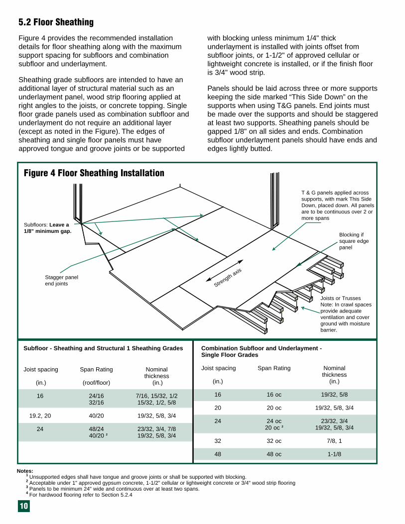
Figure 4 provides the recommended installationdetails for floor sheathing along with the maximumsupport spacing for subfloors and combinationsubfloor and underlayment.
Sheathing grade subfloors are intended to have anadditional layer of structural material such as anunderlayment panel, wood strip flooring applied atright angles to the joists, or concrete topping. Singlefloor grade panels used as combination subfloor andunderlayment do not require an additional layer(except as noted in the Figure). The edges ofsheathing and single floor panels must haveapproved tongue and groove joints or be supported
with blocking unless minimum 1/4" thickunderlayment is installed with joints offset fromsubfloor joints, or 1-1/2" of approved cellular orlightweight concrete is installed, or if the finish flooris 3/4" wood strip.
Panels should be laid across three or more supportskeeping the side marked “This Side Down” on thesupports when using T&G panels. End joints mustbe made over the supports and should be staggeredat least two supports. Sheathing panels should begapped 1/8" on all sides and ends. Combinationsubfloor underlayment panels should have ends andedges lightly butted.
Subfloors: Leave a1/8" minimum gap.
Stagger panelend joints
T & G panels applied acrosssupports, with mark This SideDown, placed down. All panelsare to be continuous over 2 ormore spans
Joists or TrussesNote: In crawl spacesprovide adequateventilation and coverground with moisturebarrier.
Notes:1 Unsupported edges shall have tongue and groove joints or shall be supported with blocking. 2 Acceptable under 1" approved gypsum concrete, 1-1/2" cellular or lightweight concrete or 3/4" wood strip flooring3 Panels to be minimum 24" wide and continuous over at least two spans.4 For hardwood flooring refer to Section 5.2.4
Subfloor - Sheathing and Structural 1 Sheathing Grades
Joist spacing Span Rating Nominalthickness
(in.) (roof/floor) (in.)
16 24/16 7/16, 15/32, 1/232/16 15/32, 1/2, 5/8
19.2, 20 40/20 19/32, 5/8, 3/4
24 48/24 23/32, 3/4, 7/840/20 2 19/32, 5/8, 3/4
Combination Subfloor and Underlayment - Single Floor Grades
Joist spacing Span Rating Nominalthickness
(in.) (in.)
16 16 oc 19/32, 5/8
20 20 oc 19/32, 5/8, 3/4
24 24 oc 23/32, 3/420 oc 2 19/32, 5/8, 3/4
32 32 oc 7/8, 1
48 48 oc 1-1/8
Blocking ifsquare edgepanel
Strength axis
5.2 Floor Sheathing
Figure 4 Floor Sheathing Installation

11
Table 4 contains the recommended fastening methods for OSB floor sheathing. Standard nailsizes and lengths are given in Table 5. Often power-driven nails are used to fasten the sheathing. This isacceptable as long as the nails are not over-drivenso that they punch into the panel. Wood screws arealso an acceptable method of fastening.
The performance of any floor system can beenhanced, if in addition to the normal nailing, the
sheathing panel is glued to the supporting joistswith an elastomeric adhesive and the tongue andgroove edges are glued together. The glue createscomposite action between the joists and thesheathing, which stiffens the floor and reducesvibration. In fact, many new engineered floor joistproducts such as I-joists can be installed onlonger spans when the subfloor is glued. Use only solvent based glue conforming to APAspecification AFG-01, or ASTM standard D3498.
5.2.1 Fastening for floor sheathing
After the building is closed in and heated and justbefore laying the finished floors, sweep and vacuumthe panels. Carefully check the floor surface for protruding nail heads and make sure all panels arefully nailed. Adverse moisture conditions may havecaused some panel edge swelling. Sand paneledges flush and ensure panels are dry beforeinstalling finished floor. Carpet and parquet flooringmay be installed on top of the panels following goodpractice and the flooring manufacturer’s directions.
For adhesive applied resilient flooring a separate panelunderlayment must be installed (see section 5.3).Use an adhesive recommended by the flooring manufacturer that is not rigid setting sulphite liquoror alcohol resin-based. Other resilient finish floorcoverings are often suitable for installation directlyover single floor grades. If the sheathing was subjected to severe moisture conditions during construction it may be necessary to level the entiresurface with a light sanding.
Application 1 Fastener 2, 3, 4 Number and Location 3
Subfloor and Single Floor
1/2" thick or less 6d common or 6" o/c at panel edgesdeformed shank nails 12" o/c along intermediate
supports (10" for single floor)
19/32" to 3/4" thick 8d common or 6" o/c at panel edgesdeformed shank nails 12" o/c along intermediate
supports (10" for single floor)7/8" to 1" thick 8d nails
Roof Sheathing
1" thick or less 8d common or 6" o/c at panel edgesdeformed shank nails 12" o/c along intermediate supports
Wall Sheathing
1/2" thick or less 6d common or 6" o/c at panel edgesdeformed shank nails 12" o/c along intermediate supports
19/32" to 3/4" thick 8d nails 6" o/c at panel edges12" o/c along intermediate supports
Table 4 Fastening schedule for OSB sheathing
5.2.2 Installing finished flooring over combination subfloor and underlayment
Notes:1 Nails should be 3/8" from panel edge2 Box nails, spiral nails, or staples can be used in lieu of common nails. Check with your local building inspector.3 Larger nails or closer spacings may be required in high wind or seismic areas.4 Schedule is per the 2000 International Building Code. For power driven nails or staples for use in all types of building
construction, consult NER 272 issued by ICC-ES to ISANTA (www.icces.org).

12
Log Hauling and Sorting Jackladder
Blending
Forming Line Pressing
Figure 1 OSB Manufacturing Process
Drying
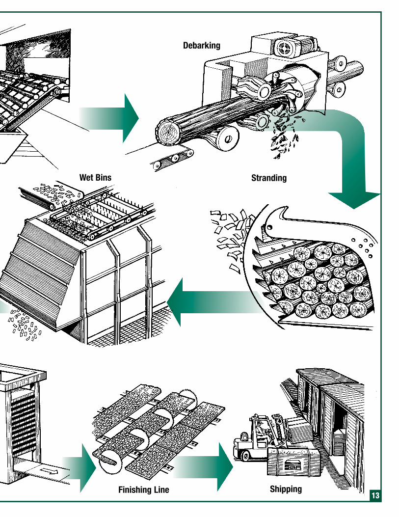
Debarking
StrandingWet Bins
Finishing Line Shipping13

14
Concrete toppings are often used over panel subfloors to increase the sound insulation properties and fire resistance of the floor system.Light-weight gypsum concrete manufacturers typically recommend using 3/4" of concretepoured directly over 3/4" tongue and groove subfloor with the joists spaced at 16" to 24" on center. However, 3/4" of concrete over 19/32"(40/20) subfloor with joists at 19.2" on center, or 1" of concrete for joists at 24" on center, is oftenacceptable to local building officials. The subfloorshould be clean and free of contaminants beforeapplication.
5.2.4 Hardwood floors
The National Wood Flooring Association (NWFA)and the National Oak Flooring ManufacturersAssociation (NOFMA) recognize the use of 23/32"(3/4" nominal) OSB subfloor under hardwood flooring. Recommended support spacings areshown in Table 6. The subfloor should be glued-nailed to the framing with adhesives conforming toAPA specification AFG-01. Tongue and groove orpanel blocked edges should also be glued.
The thick panel provides good nail holding powerand the reduced support spacings along with the gluing will create a stiff floor that will help reducefloor squeaks after hardwood floor installation.
It is important that the subfloor be dry when thehardwood is installed, otherwise buckling andsqueaking of the hardwood floor will occur whenthe subfloor dries out. Should it become wet during construction it must be dried out and themoisture content checked with a moisture meter to assure that it is within limits acceptable to thehardwood manufacturer.
The subfloor should be level, especially the jointsbetween panels. Any ridges at panel edges shouldbe sanded smooth before hardwood installationusing a heavy-duty floor sander and a moderatelycoarse grit sandpaper. Following sanding, anyareas of the floor that squeak should be renailed.
For installation of the flooring, follow the recommendations of the manufacturer or theNOFMA or NWFA. Where possible, orient thehardwood strips perpendicular to the floor framing.
Table 5 Nail Weight, Length and Gage
Table 6 Recommended Floor Sheathing for Hardwood Flooring
5.2.3 Concrete topping over OSB subfloor
OSB rated floor sheathing Recommended support spacing (in.)40/20, 20 oc 1 1248/24, 24 oc 19.2
32 oc 2448 oc 32
Note: 1 23/32" (3/4" nominal) thick panels are recommended for best performance.
Sizes of bright, common wire nailsSize Length Diameter No. per
(inches) (inches) pound4d 1-1/2 0.102 3166d 2 0.113 1818d 2-1/2 0.131 106
10d 3 0.148 6912d 3-1/4 0.148 6316d 3-1/2 0.162 49 20d 4 0.192 31
Sizes of helically and annularly threaded nailsSize Length Diameter
(inches) (inches)6d 2 0.102 8d 2-1/2 0.120
10d 3 0.13512d 3-1/4 0.13516d 3-1/2 0.148 20d 4 0.177

15
Table 7 provides the minimum recommended floorsheathing systems for ceramic or other tiles.For good performance it is important that the floorsystem be as stiff as possible. Therefore, the use ofthicker subfloor (i.e. 23/32" or 48/24 span rating) or
underlayment along with reduced fastener spacingwill enhance the performance of the floor. Prohibittraffic on the tile until the mortar or adhesive hasset in order to avoid cracking.
5.2.5 Ceramic Tile
Floor vibration or “bounciness” usually results froma combination of maximum floor joist span andspacing, with minimum subfloor thickness and otherconstruction details. To increase floor stiffness andsignificantly improve overall floor performance,several options are available such as increasing the
subfloor thickness beyond the minimum coderequirements; nailing and field gluing the subfloor tothe joists; reducing the joist spacing; reducing thejoist spans to a smaller deflection limitation due tolive load or installing improved bracing systems.Please consult with SBA for additional information.
5.2.6 Floor Vibration
Minimum subfloor
Panel Thickness (in) 3 Underlayment (in) Tile Installation
19/32 min. 7/16 CBU 4, 5 Dry-Set mortar or latex-portland cement mortar
19/32 none Cement mortar (1-1/4") 7
19/32 11/32 8 Organic adhesive
19/32 15/32 6, 8 Epoxy mortar
Table 7 Recommended Floor Sheathing Systems for Ceramic Tile Flooring 1, 2
Notes:1 Based on ANSI Standard A108 and specifications of the Tile Council of America for plywood.2 Joist spacing not to exceed 16" oc. Joists should be blocked with solid blocking on 4" centers in high traffic areas.3 OSB performance based sheathing with a span rating of 40/20 (19/32" thick)4 Bond cementitious backer units (CBUs) to subfloor with latex - Portland Cement or epoxy mortar prior to spreading mortar for
setting ceramic or other tile.5 Leave 1/8" space at panel ends and edges. Fill joints with mortar.6 Leave 1/4" space at panel ends and edges; trim panels as necessary to maintain end spacing and panel support on framing.
Fill joints with epoxy mortar when it is spread for setting tile. With single layer subfloor use solid blocking under all panel endand edge joints, including tongue and groove joints.
7 Use No.15 asphalt felt or 4-mil polyethylene sheeting over subfloor. Reinforce mortar with wire mesh.8 Underlayment or Exterior grade plywood.

16
When fastening, begin atcontact corner and workdiagonally across panel
Offset paneledge joints onejoist space fromsubfloor paneljoints
Minimum 1/4" spacearound room perimeter
Butt edges into lightcontact
Offset panel joints4" minimum
Space fasteners1/2" minimum frompanel edge
Sanded OSBunderlayment
Fastener Size & Type
Nail Staple
Size/Type Gage Length Crown Width
1/4" 18 7/8" 3/16"
3/8" 16 1 1/4" 7/16"
3d
Ring
Shank
Sanded
OSB
Panel Thickness
Figure 5 provides the recommended installationdetails for OSB floor underlayment along withfastener size and types. Sanded OSB floorunderlayment is suitable for use under many finishedflooring products such as: felted synthetic fiber orcarpet; embossed resilient flooring; smooth resilientflooring; cushion back resilient flooring; perimeterglued or loose lay resilient flooring. Before applyingthe underlayment thoroughly sweep or vacuum cleanthe subfloor. Reset all popped nails and re-nail anyloose panels. When underlayment is applied overpanel subfloors, apply the panels immediately prior toinstallation of the finished flooring.
When underlayment panels are applied over lumberboard subfloors, apply panels parallel to joists ifboards are perpendicular to joists. Underlaymentpanels may be applied in either direction if boardsare at an angle less than 75° to joists.
To fasten, begin nailing or stapling at contact cornerof underlayment panels and work diagonally acrosspanels. Make sure the panels are in firm contact withthe subfloor when driving the fasteners. Space nailsat 4" o.c. on panel edges, and 8" o.c. in the center ofthe panel. Or use staples at 3" o.c. on panel edges,and 6" o.c. elsewhere. When gluing underlayment tosubfloor use only solvent based glues.
5.3 Floor Underlayment
Figure 5 Floor Underlayment Installation
Note: Check availability of underlaymentgrade before specifying.

17
Edges Supported 1 Edges UnsupportedSupport spacing Span Rating Nominal Thickness Span Rating Nominal Thickness
(roof/floor) (in.) (roof/floor) (in.)
Sheathing Grade
12 12/0 5/16 12/0 5/16
16 16/0 5/16, 3/8 16/0 5/16, 3/8
20 20/0 5/16, 3/8 20/0 5/16, 3/824/0 3/8, 7/16
24 24/0 3/8, 7/16, 1/2 24/0 15/32, 1/224/16 7/16, 15/32, 1/2 24/16 7/16, 15/32, 1/2
32 32/16 15/32, 1/2, 5/8 40/20 19/32, 5/8, 3/4
40 40/20 19/32, 5/8, 3/4
48 48/24 23/32, 3/4
Single Floor Grade
24 or less 16 oc 19/32, 5/8 16 oc 19/32, 5/8
32 20 oc 19/32, 5/8, 3/4 20 oc 19/32, 5/8, 3/4
40 24 oc 23/32, 3/4
48 24 oc 23/32, 3/4
5.4 Roof Sheathing
Notes:1 Lumber blocking, panel edge clips (one midway between each support, except two equally spaced between supports when
span is 48"), tongue and groove panel edges, or other approved type of edges support.2 Panels to be minimum 24" wide and continuous over at least two supports.3 Panel thicknesses and span ratings apply for pitched or flat roofs; where flat roofs are used as walking decks, the
requirement for floors shall apply. 4 For enhanced performance SBA recommends a minimum 24/16 rating at 16" or 20" oc and minimum 32/16 at 24" oc.
Figure 6 provides the recommended installationdetails for roof sheathing along with the maximumsupport spacing and minimum nominal thickness.
Before installing the sheathing the rafters or uppertruss chord should be checked to assure that theyare aligned, straight and even. Curved or unevenrafters or upper truss chords affect the finished roof.
Stagger panel end joints
Apply panels across supportsAll panels are to be continuous across two or more spans
Supports – Rafters, Trusses or Joists
Warning: Roof sheathing may be extremely slippery when wet, covered with frost, snow, ice or sawdust. Installers of roof sheathing should wearrubber-soled footwear and exercise caution, especially on roof slopes exceeding 4 in 12. Based on recent studies, soles of thermoplastic rubberprovide the best traction of the sole materials tested. Place screened surface of panel face up.Note: Panels that get wet should be allowed to surface dry before applying shingles. Protect uncoated edges from direct rain exposure.
Leave a 1/8" minimum gap on all edges
Edge clips or T & G edges if specified
Figure 6 Roof Sheathing InstallationSupport panel edges at ridge

The panels should be installed textured side up withtheir long direction across the rafters or trusschords. Long panel edges should be supported orjoined with edge clips where required. A 1/8" gapshould be left at the panel edges and ends to allowfor movement due to changes in humidity. Panelsshould be staggered at least two supports and endjoints must lie over supports.Table 4 contains the recommended fasteningmethods for OSB roof sheathing. The installershould stand over the rafter or truss when nailing.As roof sheathing may be slippery when wet,covered with frost, snow ice, or sawdust, installersshould wear rubber soled footwear, use appropriatesafety equipment and use extreme caution whenworking on sloping roofs.
5.4.1 High Wind AreasExtra fastening and closer spacing is required inhigh wind or seismic areas. Other requirements mayalso apply. Check with the local building authorityfor these special requirements.
5.4.2 Ventilation of Attic and Roof Spaces
In order to minimize the impact of moisture build-upin attic spaces, it is essential that adequate
ventilation be installed with 50% of the ventilation atthe roof ridge and 50% at the soffit area. Buildingcodes specify that the minimum unobstructed ventarea equal not less than 1/300 of the total insulatedceiling area if a maximum 1 perm vapor retarder isinstalled on the warm side of the ceiling insulation.Otherwise the free vent area must equal not lessthan 1/150 of the insulated area. Vent roof asspecified in the appropriate building code or asshown on the approved drawings. The roof shouldbe dry prior to shingling and should be shingled assoon as possible after installation of sheathing.
5.4.3 Prevention of Ice DammingIce damming occurs in extreme cold climates and isdue to heat transfer from the attic space to theshingles melting the snow during the day timeperiod. At night, the snow melt freezes. Repeatedcycles of freeze thaw cause a ridge of ice trappingthe snow melt as it flows down the roof. The snowmelt backs up under shingles and soaks thesheathing. A continuous layer of “ice shield” or otherheavy waterproof material must be installed fromthe edge of the exterior wall 3 feet up the roof underthe shingles to protect the roof sheathing.
18

5.5 Wall Sheathing
Notes:1 Panels to be minimum 24" wide typically. Minimum width to be 48" when used as bracing.2 For panel sheathing applied with strength axis parallel to the studs, the minimum thickness is 3/8" at 16" oc and 7/16" at 24" oc.
Figure 7 provides the recommended installationdetails for wall sheathing along with the maximumsupport spacing. Where stucco is to be applied overthe sheathing, codes often require that the sheathingpanels be at least 1/2" thick unless the lath isfastened directly to the wall studs. However, SBArecommends a minimum 19/32" panel covered with adouble layer of asphalt impregnated sheathing paperprior to stucco application.
Wall sheathing panels may be installed vertically orhorizontally. A 1/8" gap should be left between panels
and around openings for windows and doors.The required fastening for wall sheathing is shown inTable 4. Blocking or diagonal bracing is not requiredunless specified by the building designer or localbuilding regulation.
Sheathing paper is generally not required over OSBunless stucco, non-wood siding or in some casesbrick veneer is used for the exterior finish (consult theapplicable building code).
Framing
Leave a 1/8" minimumgap on edges and aroundopenings
Support all paneledges if panels areused for bracing oron shear walls
Stagger vertical joints inhorizontal applications
Figure 7 Wall Sheathing InstallationPanel sheathing applied with or across supports as shown, and notpermanently exposed to the weather.
19
Stud spacing 1 Span Rating Nominal thickness 2
(in.) (in.)16 12/0 5/16, 3/8
16/0 5/16, 3/8 20/0 5/16, 3/8
Wall - 16 5/16, 3/824 24/0 3/8, 7/16, 15/32, 1/2
24/16 3/8, 7/16, 15/32, 1/232/16 3/8, 7/16, 15/32, 1/2
Wall - 24 3/8, 7/16, 15/32, 1/2Table is valid for both cases where the sheathing is used as a siding base or where the siding is nailed to the framing studs.

20
Table 8 provides the maximum allowable loads forSBA rated OSB roof sheathing panels. This tablehas been developed following extensive testing ofthese products in research facilities plus manyyears of successful application in construction.In addition, the panels meeting PS 2 have beenperformance tested for a 35 psf loading with adeflection limit of L/240, where L is the spacingbetween supports.OSB rated floor sheathing panels meeting PS 2have been tested for a 100 psf uniform load with adeflection limit of L/360 for 16" to 32" support spacings. The 48" spacing panels are performancetested for 80 psf with the same deflection limit.
OSB structural sheathing manufactured by SBAmembers meets the Exposure 1 durability requirements of PS 2. Sloped OSB roofs will allowrain water to run off. If ponding occurs on floors orother flat surfaces SBA recommends that a holesaw be used to drill several 1" (25mm) diameterholes in the ponding area to allow the water todrain.
OSB like other wood products should be protectedfrom excess moisture. Ensure that sheathing paperor “house wrap” is properly installed under stucco,vinyl siding or brick veneer. Provide adequate flashing over openings in brick veneer walls so thatthe wall cavity will drain when moisture penetratesthe brick. In addition, provide adequate flashing atall roof and wall openings and at changes in horizontal and vertical direction (for example insidecorners, valleys, dormers).
OSB is a wood based product. Reasonable care isrequired in warehousing and on the job site to protect panels from mechanical damage andlengthy exposure to adverse moisture conditions.For best results handle panels as little as possible.Ship in the original lift loads if possible. Use care inhandling the panels to avoid damaging corners andedges. If storing SBA panels for long periods, storelifts indoors or under cover with enough supportsthat panels remain flat. Provide air circulationaround panels by keeping covers open and awayfrom sides and bottoms of lift loads.
5.6 Maximum loads for OSB panels
5.7 Moisture during Construction
5.8 Detailing and Good Construction Practice
5.9 Shipping, handling and storage
Span Panel Maximum span (in) Allowable live loads (psf) 2
Rating Thickness with without spacing of supports center-to-center (in)(in) edge edge 12 16 20 24 32 40 48
support 3 support
16/0 5/16, 3/8 16 16 55 30
24/0 3/8, 7/16, 1/2 24 20 4 170 100 60 30
24/16 7/16, 1/2 24 24 5 190 100 65 40
32/16 15/32, 1/2, 32 28 5 220 155 120 70 3019/32, 5/8
40/20 19/32, 5/8 40 32 200 165 125 60 30
48/24 23/32, 3/4 48 36 210 165 95 45 35
Table 8 Maximum Allowable Loads for SBA OSB Rated Roof Sheathing 1
Notes:1 Values are valid when long dimension is across supports and were provided from work done by APA.2 Values include an allowance for a dead load of 10 psf. If higher dead loads are used the live load should be reduced
accordingly.3 Tongue and groove edges, panel edge clips (one between each support, except two between supports 48 in. on center),
lumber blocking, or other.4 24" for 1/2" panels.5 For enhanced performance SBA recommends a minimum 24/16 rating at 16" oc and minimum 32/16 rating at 24" oc.

21
Structural Insulated panels (SIPS), also known asfoam-core sandwich panels, are becoming increasingly popular for use as structural walls,roofs and floors (see Figure 8). These products
provide an alternatesolution for ownersand builders concerned withenergy efficiencyand dwindling natural resources.These panels aremanufactured insizes from 4'x 8' to8'x 24' and havequality certified OSBfaces glued to eitherprecast or foamed inplace rigid foamcores. They aremanufacturedthroughout the U.S.and Canada in
modern quality controlled plants to fit a variety ofhome designs and can easily be erected on prepared foundations by trained installers.Individual manufacturers certify capacities for thepanels in accordance with an ASTM Standard or anICBO evaluation report. Individual manufacturershave National and local code approval under theNational Evaluation System. For more informationand a list of panel manufacturers, contact theStructural Insulated Panel Association (www.sips.org).
Proprietary OSB is used extensively for the webs ofprefabricated wood I-joists. Wood I-joists can beused for longer spans than conventional lumber,and because they are manufactured at a low moisture content greatly reduce performance problems such as nail pops and squeaky floors thatsometimes occur with conventional lumber.
Individual I-joist manufacturers certify design valuesfor their products under ASTM Standard D-5055and also provide a wide range of design informationfor use by the specifier or builder. Wood I-joists canbe cut to desired lengths either on the job site or byorder from the manufacturer. Most joists are supplied with knockout ports for the installation ofelectrical or heating systems. These knockout ports
are located within the joists so as not to affectstrength performance. SBA recommends the use of min. 1" thick OSB rim joists equal in depth to the I-joist as part of the floor system for added strengthand load-carrying capacity. (Refer to ICBO ESReport 124, Acceptance Criteria for Wood-BasedRim Board Products). SBA discourages the use ofnailed in place ordinary OSB wall sheathing alonein load bearing rim joist applications. For moreinformation contact the SBA or members of theWood I-joist Manufacturers Association.
Designers and builders are utilizing the superiorload-carrying capability of the wood I-joist alongwith thicker (7/8" or 1") OSB subfloor panels to construct an engineered floor system that givessuperior performance in terms of deflection andvibration. This system is very popular for long spans or under ceramic or marble tile finishedfloors. For more information contact the SBA or the I-joist manufacturer.
OSB can be used in a variety of applications in renovation projects. In addition to sheathing, otherapplications include replacing or levelling originalfloors, closing exterior openings due to relocation ofdoors and windows, or modifying roofs to allow forconstruction of dormers or lofts. Solid OSB panelsare often used to restrict entry to buildings beingrenovated or as a safety fence around the renovation site. The versatile panels also makeexcellent hidden forms for the construction of concrete platforms or exterior concrete stairs.
OSB panels are commonly used in industrial applications. The strength, workability, versatility, value and lack of formaldehyde emissions, makethem excellent alternatives to plywood and solidwood. Panels specifically identified or rated for roof,wall, and floor applications in wood frame construction may be used directly, or SBA memberscan customize panel thickness, size or properties ofOSB for specific applications. These advantages havebeen recognized by industrial buyers particularly forcrating and packaging, materials handling andmanufactured housing applications. More and moreOSB is chosen for crating, pallets, bins, furnitureframes, display racks and store fixtures.
6.0 OTHER USES FOR OSB
6.1 Structural Insulated Panels
6.2 Wood I-joists
6.2.1 Engineered Floor Systems
6.3 Renovation
6.4 Industrial Applications
Interior sheathing
Exterior sheathing
FoamCore
Figure 8 Typicalstructural insulated panel

22
OSB sheathing panels can be used to create horizontal diaphragms and shearwalls in order tobrace buildings for wind and seismic loads. Tables 9 and 10 contain the maximum allowable shearforces (plf) for shearwalls and diaphragms. Notethat proper design of shearwalls and diaphragmsinclude sizing the perimeter members for axialforces. Also, the connections between thediaphragm and shearwall must be engineered.The shearwall must also be adequately anchored tothe supporting wall or foundation and the corners fastened down to prevent the wall from overturningunder lateral loads. Please consult with your localbuilding official for any specific requirements.
Alternatively shearwalls and diaphragms can bedesigned by principles of mechanics withoutlimitations by using values for nails (or staples)strength and panel design properties.
The ASCE Standard ASCE 16-95 “LRFD Design ofEngineered Wood Construction” is referenced in themodel U.S. building codes. The design procedure isknown as load and resistance factor design and isan alternative to traditional allowable stress design.The standard combines requirements for solid sawnlumber, glued-laminated timber, structural-usepanels and other engineered wood products underone cover. A companion design manual is availablefrom the American Wood Council. APA and SBAhave jointly developed a Structural-Use panelsupplement for this manual that includes designcapacities for OSB.
A second manual developed by the American Wood Council provides guidelines for allowablestress design procedures set forth in the 2005National Design Specifications for WoodConstruction. This manual now in its third revisededition contains two supplements with informationon OSB structural use panels and shearwalls anddiaphragms.
In Canada design values for OSB are given in thewood design standard CSA O86-01 for panels meeting CSA-O452 “Design Rated OSB” or CSA-O325 “Construction Sheathing”. Contact SBAfor additional design information.
The use of OSB panels over metal framing members is possible with modern fastening methodssuch as self-drilling, self-tapping screws or screw-shank nails. These can be used to attach a widerange of panel thicknesses to steel flanges, or lightermembers such as cold-formed steel sections.Construction adhesives recommended by the metalframing manufacturers should be used with hardened screw-shank nails.
Since threads extend only part way up the shank of screws or nails, it is important to specify afastener length sufficient to engage the metalframing. Load-span recommendations are the sameas for wood-frame systems described elsewhere inthis manual. The prescriptive method for ResidentialCold-Formed Steel Framing (referred byorganizations such as AISI, USHUD and NAHBRC)allows OSB wall sheathing to be fastened to steelstuds with #8 screws (bugle head, flat head orsimilar) with a minimum head diameter of 0.29"(8 mm), at every 6" on panel edges and 12" alongintermediate supports. This applies only in highwind areas with less than 100 mph winds and inseismic zones 1, 2 or 3.
OSB shearwall panels over metal studs are referenced in allowable shear tables of the 1997UBC and the 2003 IBC.
6.7 OSB Panels over Metal Framing
6.5 Horizontal Diaphragms and Shearwalls
6.6 Engineering Design

Panel Grade Minimum Minimum Nail Nail spacing at panel edges (in.) 3
nominal nail size 7
panel penetration (common or 6 4 3 2 4
thickness into framing galv. box)
Structural 1 5/16" 1-1/4" 6d 200 300 390 510
3/8" 1-1/2" 8d 230 5 360 5 460 5 610 5
7/16" 1-1/2" 8d 255 5 395 5 505 5 670 5
15/32" 1-1/2" 8d 280 430 550 730
15/32" 1-5/8" 10d 6 340 510 665 870
Sheathing 5/16" 1-1/4" 6d 180 270 350 450
3/8" 1-1/4" 6d 200 300 390 510
3/8" 1-1/2" 8d 220 5 320 5 410 5 530 5
7/16" 1-1/2" 8d 240 5 350 5 450 5 585 5
15/32" 1-1/2" 8d 260 380 490 640
15/32" 1-5/8" 10d 6 310 460 600 770
19/32" 1-5/8" 10d 6 340 510 665 870
Notes:1 These values are for designs due to seismic loads, and are allowed to be increased by 40 percent for wind loading.
2 All panel edges backed with 2" nominal or wider framing. Panels installed either horizontally or vertically. Space nails at 6" oncenter along intermediate framing members for 3/8" and 7/16" panels installed on studs spaced 24" on center and 12" oncenter for other conditions and panel thicknesses. Allowable shear values for framing members of other species may be obtained by multiplying the tabulated values by a specific gravity adjustment factor = [ 1 - (0.5 - SG) ] ≤ 1.0. Consult the NDS for SG values.Allowable shear values are valid when OSB is fastened directly to framing. For installation over gypsum sheathing, refer toapplicable building code.
3 Where panels are applied on both faces of a wall and nail spacing is less than 6" on center on either side, panel joints shallbe offset to fall on different framing members or framing shall be 3" nominal or thicker and nails on each side staggered.
4 Framing at adjoining panel edges shall be 3" nominal or wider and nails staggered where nails are spaced 2" on center.
5 The values for 3/8" and 7/16" panel may be increased to values shown for 15/32" panels, provided studs are spaced amaximum of 16" on center or panels are applied with long dimension across studs.
6 Framing at adjoining panel edges shall be 3" nominal or wider and nails shall be staggered where 10d nails having penetrationinto framing of more than 1-5/8" are spaced 3" or less on center.
7 Staples may be permitted in lieu of nails. Please consult with your local building code. Allowable shear values are given in the2003 International Building Code.
23
Table 9 Allowable Shear Forces (plf) for OSB Shearwalls with Douglas Fir-Larch or Southern Pine Framing 1, 2

24
Panel Common Min. Min. Min. Blocked Diaphragms Unblocked DiaphragmsGrade Nail nail panel nom. Nail spacing at diaphragm boundaries
size 5 pen. thick. width (all cases), at continuous panel edgesinto of parallel to load (Cases 3 and 4) and at Nails spaced 6" max. at
framing framing all panel edges (Cases 5 and 6) supported edges
6" 4" 2-1/2" 2 2" 2
Nail spacing at other panel edges Case 1 All other configurations
6" 6" 4" 2 3" 2
Structural 1 6d 1-1/4" 5/16" 2" 185 250 375 420 165 1253" 210 280 420 475 185 140
8d 1-1/2" 3/8" 2" 270 360 530 600 240 1803" 300 400 600 675 265 200
10d3 1-5/8" 15/32" 2" 320 425 640 730 285 2153" 360 480 720 820 320 240
23/32"4 3" 650 940 4" 755 1080
Sheathing 6d 1-1/4" 5/16" 2" 170 225 335 380 150 1103" 190 250 380 430 170 125
3/8" 2" 185 250 375 420 165 1253" 210 280 420 475 185 140
8d 1-1/2" 3/8" 2" 240 320 480 545 215 1603" 270 360 540 610 240 180
7/16" 2" 255 340 505 575 230 1703" 285 380 570 645 255 190
15/32" 2" 270 360 530 600 240 1803" 300 400 600 675 265 200
10d3 1-5/8" 15/32" 2" 290 385 575 655 255 1903" 325 430 650 735 290 215
19/32" 2" 320 425 640 730 285 2153" 360 480 720 820 320 240
23/32"4 3" 645 9354" 750 1075
Table 10 Allowable Shear Forces (plf) for OSB Horizontal Diaphragms with Douglas Fir-Larch or Southern Pine Framing 1
Notes:1 These values are for designs due to seismic loads, and are allowed to be increased by 40 percent for wind loading.
Space nails 12" on center along intermediate framing (6" o.c. where supports are 48" apart).Allowable shear values for framing members of other species may be obtained by multiplying the tabulated valuesby a specific gravity adjustment factor = [ 1 - (0.5 - SG) ] ≤ 1.0. Consult the NDS for SG values.
2 Framing at adjoining panel edges shall be 3" nominal or wider and nails shall be staggered where nails are spaced 2" or 2-1/2"on center.
3 Framing at adjoining panel edges shall be 3" nominal or wider and nails shall be staggered where 10d nails havingpenetration into framing of more than 1-5/8" are spaced 3" or less on center.
4 Two lines of fasteners are required for 23/32" sheathing. Values do not apply to the Uniform Building Code, or IBC.5 Staples may be permitted in lieu of nails. Please consult with your local building code. Allowable shear values are given in the
2003 International Building Code.
Note: Framing is permitted in either direction for blocked diaphragms

Deflection :The amount a panel deflects between two supports when carrying a load. Maximum deflection for roofloads is usually L/240 for live load only or L/180 for total load. For floor loads, maximum deflection isusually L/360 for live load plus dead load.
Major axis (Strength axis) :The axis with the greater stiffness and strength in bending. For OSB, the direction of alignment of thestrands in the face layers of the panel.
Minor axis :The axis with the lesser stiffness and strength in bending. For OSB, the direction at right angles toalignment of the strands in the face layers of the panel.
Nominal thickness :The trademark-specified thickness marked on the panel.
OSB:An abbreviation for Oriented Strand Board; a type of mat-formed panel with oriented or aligned strands,resulting in directional properties. OSB conforms to standards such as PS 2, CSA O325 or other nationalstandards.
Performance Rated (or Rated) :Panels which have been tested to meet specific loading and deflection conditions from impact,concentrated static, uniformly distributed and racking loads for panels intended to span two or moresupports.
Strand :A specialized knife cut wood flake of controlled thickness and a length along the grain orientation of atleast twice and usually many times its width.
Thermosetting binder :An adhesive or binder which when fully cured is not softened by heat, and will not break down in thepresence of moisture.
Touch Sanded :A process that removes material from the panel surface to provide a uniform thickness. Tongue andGroove panels are usually touch sanded.
Wafer :A specialized knife cut wood flake having a controlled length of at least 1 1/4" (30mm) along the grain, a controlled thickness and a variable width.
APA - The Engineered Wood Association :An industry association of plywood, OSB, glulam and engineered wood manufacturers that supplied someinformation found in this manual. APA provides a quality assurance program for its member companies.
HUD:The U.S. Department of Housing and Urban Development. HUD sets standards for government financedconstruction and manufactured homes.
PSI:Professional Service Industries Inc, Pittsburgh Testing Laboratory; a compliance, assurance and inspectionagency with wood products testing facilities in Eugene, OR.
TECO:A U.S. national inspection and testing agency with wood products testing facilities in Madison, WI, Eugene,OR and Shreveport, LA.
APPENDIX A - GLOSSARY OF TERMS
25

APPENDIX B - SBA MEMBER PLANT LOCATIONS
1
7
2
Poland
France
3
4
6
Brazil
U.S.A.
5
26
Canada

SBA MEMBER COMPANIES
Member Companies Address Telephone and Fax Mill Locations Map #Numbers (Sales Office) Reference
Grant Forest Products Inc. 2233 Argentia Road 905-858-3200 Englehart, ON Canada 1Mississauga, ON Canada L5N 2X7 905-858-3208 Timmins, ON Canada 2
ISOROY S.A. 54-56 rue d’Arcueil, SILIC 135 33-1-56-30-20-00 Châtellerault, France 3(Sonae Industria) Immeuble Amsterdam 33-1-57-02-12-71
94523 Rungis Cédex, France
Kronopol Sp. z o.o. ul. Serbska 56 48-68-363-1100 Zary, Poland 4(Krono Group Swiss) 68-200 Zary, Poland 48-68-363-1262
Langboard Inc. P.O. Box 837, Hwy 84 East 229-263-8943 Quitman, GA U.S.A. 5Quitman, GA U.S.A. 31643 229-263-5535
MASISA U.S.A. 900 Circle 75 Parkway, Suite 720 770-405-261726 Ponta Grossa, Brazil 6Atlanta, GA, U.S.A. 30339 770-405-2601
Panneaux Tembec OSB 775, 122 Street 888-343-0735 St-Georges de Champlain, QC 7(Tembec Forest Products Group) St-Georges de Champlain, QC 819-538-0595 Canada
Canada G9T 5K7
27

BASF Corporation
Canadian Willamette Industries Inc.
Eugene Forest Systems Ltd.
Hexion Specialty Chemicals
Huntsman Polyurethanes
NGM International Inc.
Tembec Chemical Products Division
Valspar Corporation
Specialty Wood Journal Thermapan Industries
Ecole Supérieure du Bois, France
Louisiana State University
Mississippi State University
Oregon State University
Pennsylvania State University
University of British Columbia
Université Laval
University of Minnesota (NRRI)
University of New Brunswick (WSTC)
University of Tennessee
University of Toronto
Virginia Polytechnic Institute
West Virginia University
Wilhelm - Klauditz Institut, Germany
Alberta Research Council
American Wood Council
Canadian Wood Council
COMACO, Mexico
European Panel Federation
Forintek Canada Corporation
North American Coalition on Green Building
Sustainable Forestry Certification Coalition, Canada
Wood Panel Bureau, Canada
Wood Promotion Network, North America
Wood WORKS!, Canada
ASSOCIATE MEMBERS
ALLIED MEMBERS
RESEARCH MEMBERS
AFFILIATED WITH
28

25 Valleywood Drive, Unit 27, Markham, Ontario, Canada L3R 5L9Telephone (905) 475-1100 Fax (905) 475-1101
Website: http://www.osbguide.com E-mail: [email protected]
ISBN 1-896479-01-4TM420