performance enhancement of soil-structure systems using a
TRANSCRIPT
Performance Enhancement of Soil-Structure Systems Using a Controlled Rocking
Aria Fathi1, S. Mohsen Haeri, Ph.D., P.E., D.I.C. 2, Mehrdad Palizi3, Mehran Mazari,
Ph.D.4, Cesar Tirado, Ph.D. 1, Cheng Zhu1
1Center for Transportation Infrastructure Systems (CTIS), The University of Texas at El Paso, 500
W. University Ave., El Paso, TX 79968; e-mail: [email protected], [email protected],
[email protected] 2Department of Civil Engineering, Sharif University of Technology, Tehran, Iran; e-mail:
[email protected] 3Department of Civil Engineering, The University of Alberta, 116 St. and 85 Ave., Edmonton, AB,
Canada; e-mail: [email protected] 4Department of Civil Engineering, California State University Los Angeles, 5151 State University
Drive, Los Angeles, CA 90032; e-mail: [email protected]
ABSTRACT
Application of performance-based design (PBD) in earthquake geotechnical design codes has been gaining
attention for the past decade. Strong vibrations (e.g., earthquake loading) may generate an uplift or a partial
separation of shallow foundations from the underneath soil. To minimize the damage and keep the
superstructure safe from the vibrations, a controlled rocking can be exploited. In this study, a finite element
method is used to investigate the effect of nonlinear behavior of foundation geomaterial on the rocking
behavior of soil-structure systems. To get a better insight about the rocking behavior of the soil-structure
system, nonlinear elastic-perfectly plastic behavior is considered for the simulated geomaterial of the
foundation. Next, a parametric study, using a wide range of geomaterials with different stiffness values, is
conducted in accordance with high-rise structures with different configurations. The results indicate that a
significant proportion of the input energy is dissipated by deploying rotational behavior of shallow
foundations especially for the structures on softer geomaterials.
Keywords: Rocking Behavior, Soil-Structure Interaction (SSI), Plasticity of Geomaterial, Performance-
Based Design, Shallow Foundations, Dynamic Finite Element Model (DFEM)
1. Introduction
Strong seismic motion causes large inertial and eccentric forces to the slender and high-rise structures. The
supporting shallow foundations beneath the structures may experience a partial separation from the
underneath soil due to the overturning moments. The uplift of one side of the foundation is simultaneously
accompanied by an increase in the shear stress on the opposite side of the foundation; therefore, a failure
mechanism may happen as the combined shear and normal stresses exceed shear strength of the
geomaterial, which might be associated with permanent displacement of the foundation. Many attempts
have been focused on predicting the behavior of the geomaterial during foundation rocking as an established
tool for performance enhancement of buildings during severe vibrations (Housner 1963; Koh et al. 1986;
Gottardi and Butterfield 1995; Zhang and Makris 2001; Gajan et al. 2005; Adamidis et al. 2014; Fathi 2014;
Abadi et al., 2015; Taghavi et al. 2015; Haeri and Fathi 2015; Shahir et al. 2016; Pak et al. 2016, Sharma
and Deng 2017, Barari et al. 2017; Sharma et al. 2018).
One of the main transitions from traditional geotechnical earthquake design to performance-based design
(PBD) is to emphasize on soil-structure interaction (SSI) (Keshavarzi and Bakhshi 2012; Rahimi et al.
2018; Lemus et al. 2018). The new practices are thus involved in design concepts to consistently achieve a
desired level of satisfaction in performance enhancement of structures during a severe earthquake. Different
approaches have been proposed different performance criteria, e.g. Ayoubi and Pak (2017) considered the
settlement as a performance criterion and were able to develop a practical formula in order to calculate the
settlement of an structure. PBD is normally justified on the basis of cyclic components of motion as
accepted in the traditional design codes (e.g., FEMA 2000). The study conducted by Anastasopoulos et al.
(2010) showed that allowing a footing to yield, instead of only the superstructure, can improve the overall
integrity of the structure during an earthquake. Plastic “hinging” of foundation is an instance of such
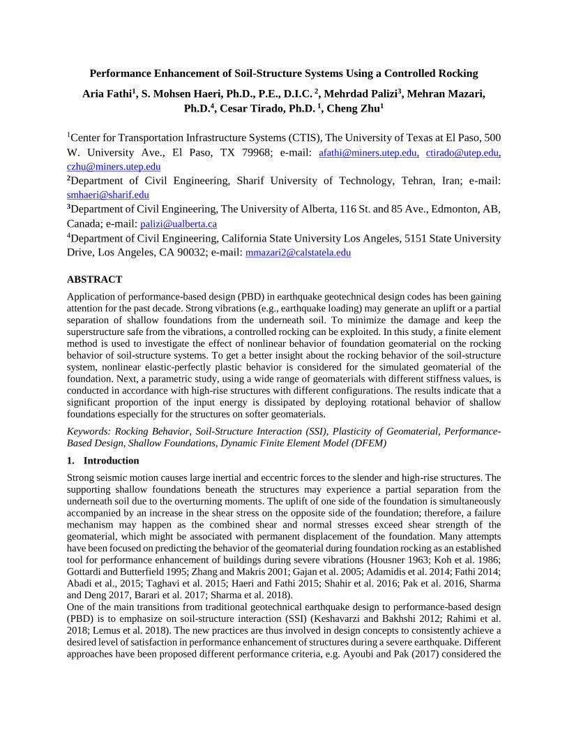
behavior. Figure 1 shows the enhancement in overall performance of the structure (the structure is not
collapsed) due to foundation hinging (Hume, 2017) which happened as a result of basin effects in
Kathmandu Valley, Nepal during the Mw 7.8 Gorkha 2015 earthquake (Ayoubi et al, 2018).
Figure 1. Plastic “hinging” of foundation due to the rocking mechanism in Kathmandu Valley, Nepal as a
result of the Mw 7.8 2015 Gorkha earthquake (Hume, 2017).
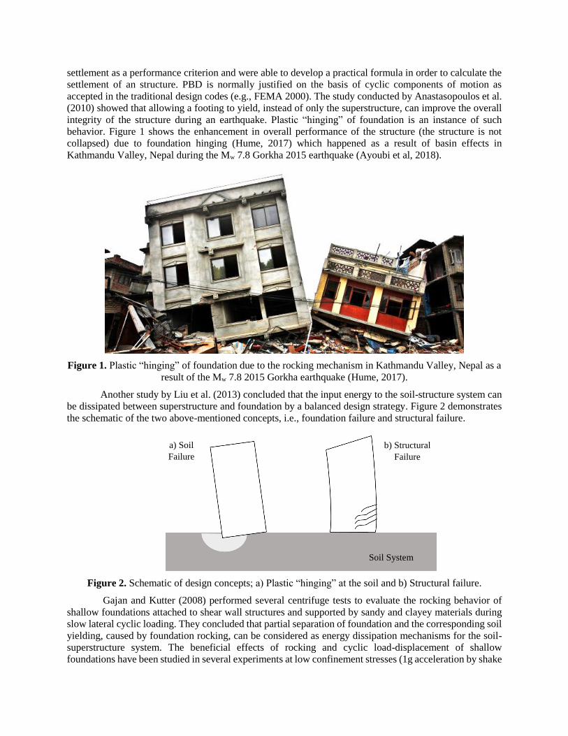
Another study by Liu et al. (2013) concluded that the input energy to the soil-structure system can
be dissipated between superstructure and foundation by a balanced design strategy. Figure 2 demonstrates
the schematic of the two above-mentioned concepts, i.e., foundation failure and structural failure.
Figure 2. Schematic of design concepts; a) Plastic “hinging” at the soil and b) Structural failure.
Gajan and Kutter (2008) performed several centrifuge tests to evaluate the rocking behavior of
shallow foundations attached to shear wall structures and supported by sandy and clayey materials during
slow lateral cyclic loading. They concluded that partial separation of foundation and the corresponding soil
yielding, caused by foundation rocking, can be considered as energy dissipation mechanisms for the soil-
superstructure system. The beneficial effects of rocking and cyclic load-displacement of shallow
foundations have been studied in several experiments at low confinement stresses (1g acceleration by shake
Soil System
b) Structural
Failure
a) Soil
Failure
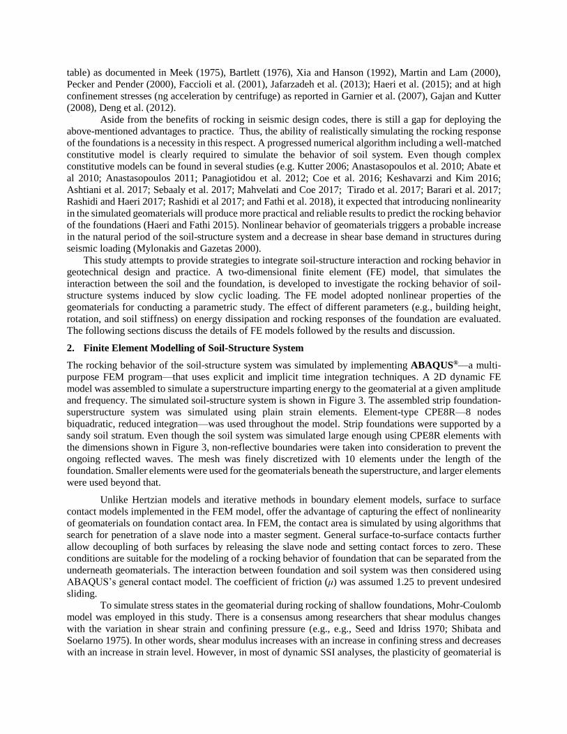
table) as documented in Meek (1975), Bartlett (1976), Xia and Hanson (1992), Martin and Lam (2000),
Pecker and Pender (2000), Faccioli et al. (2001), Jafarzadeh et al. (2013); Haeri et al. (2015); and at high
confinement stresses (ng acceleration by centrifuge) as reported in Garnier et al. (2007), Gajan and Kutter
(2008), Deng et al. (2012).
Aside from the benefits of rocking in seismic design codes, there is still a gap for deploying the
above-mentioned advantages to practice. Thus, the ability of realistically simulating the rocking response
of the foundations is a necessity in this respect. A progressed numerical algorithm including a well-matched
constitutive model is clearly required to simulate the behavior of soil system. Even though complex
constitutive models can be found in several studies (e.g. Kutter 2006; Anastasopoulos et al. 2010; Abate et
al 2010; Anastasopoulos 2011; Panagiotidou et al. 2012; Coe et al. 2016; Keshavarzi and Kim 2016;
Ashtiani et al. 2017; Sebaaly et al. 2017; Mahvelati and Coe 2017; Tirado et al. 2017; Barari et al. 2017;
Rashidi and Haeri 2017; Rashidi et al 2017; and Fathi et al. 2018), it expected that introducing nonlinearity
in the simulated geomaterials will produce more practical and reliable results to predict the rocking behavior
of the foundations (Haeri and Fathi 2015). Nonlinear behavior of geomaterials triggers a probable increase
in the natural period of the soil-structure system and a decrease in shear base demand in structures during
seismic loading (Mylonakis and Gazetas 2000).
This study attempts to provide strategies to integrate soil-structure interaction and rocking behavior in
geotechnical design and practice. A two-dimensional finite element (FE) model, that simulates the
interaction between the soil and the foundation, is developed to investigate the rocking behavior of soil-
structure systems induced by slow cyclic loading. The FE model adopted nonlinear properties of the
geomaterials for conducting a parametric study. The effect of different parameters (e.g., building height,
rotation, and soil stiffness) on energy dissipation and rocking responses of the foundation are evaluated.
The following sections discuss the details of FE models followed by the results and discussion.
2. Finite Element Modelling of Soil-Structure System
The rocking behavior of the soil-structure system was simulated by implementing ABAQUS®—a multi-
purpose FEM program—that uses explicit and implicit time integration techniques. A 2D dynamic FE
model was assembled to simulate a superstructure imparting energy to the geomaterial at a given amplitude
and frequency. The simulated soil-structure system is shown in Figure 3. The assembled strip foundation-
superstructure system was simulated using plain strain elements. Element-type CPE8R—8 nodes
biquadratic, reduced integration—was used throughout the model. Strip foundations were supported by a
sandy soil stratum. Even though the soil system was simulated large enough using CPE8R elements with
the dimensions shown in Figure 3, non-reflective boundaries were taken into consideration to prevent the
ongoing reflected waves. The mesh was finely discretized with 10 elements under the length of the
foundation. Smaller elements were used for the geomaterials beneath the superstructure, and larger elements
were used beyond that.
Unlike Hertzian models and iterative methods in boundary element models, surface to surface
contact models implemented in the FEM model, offer the advantage of capturing the effect of nonlinearity
of geomaterials on foundation contact area. In FEM, the contact area is simulated by using algorithms that
search for penetration of a slave node into a master segment. General surface-to-surface contacts further
allow decoupling of both surfaces by releasing the slave node and setting contact forces to zero. These
conditions are suitable for the modeling of a rocking behavior of foundation that can be separated from the
underneath geomaterials. The interaction between foundation and soil system was then considered using
ABAQUS’s general contact model. The coefficient of friction (μ) was assumed 1.25 to prevent undesired
sliding.
To simulate stress states in the geomaterial during rocking of shallow foundations, Mohr-Coulomb
model was employed in this study. There is a consensus among researchers that shear modulus changes
with the variation in shear strain and confining pressure (e.g., e.g., Seed and Idriss 1970; Shibata and
Soelarno 1975). In other words, shear modulus increases with an increase in confining stress and decreases
with an increase in strain level. However, in most of dynamic SSI analyses, the plasticity of geomaterial is
not considered. In this study, through an iterative process, the geomaterial modulus was adjusted with the
strain and stress levels during the FE analysis. Hence, the soil system under the application of static and
slow cyclic loadings behaves nonlinearly before the Mohr-Coulomb failure envelope, and thereafter
behaves plastic by reaching the shear strength (i.e., Mohr-Coulomb failure envelope).
Figure 3. FE model of the soil-structure system.
A nonlinear model proposed by (Seed and Idriss 1970; and Seed et al. 1986) was found to be as a
proper indicator for representing the dynamic shear moduli of granular soils. The nonlinear model is as
follows:
𝐺𝑚𝑎𝑥 = 218.82 𝐾2(max)(𝜎′)0.5 (1)
where Gmax is maximum shear modulus, K2(max) is a laboratory shear modulus coefficient measured at low
strain level, and σ' is mean effective principal stress which is defined as:
𝜎′ =𝜎1
′+𝜎2′+𝜎3
′
3 (2)
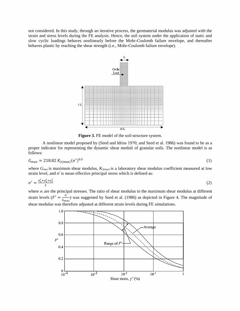
where σi are the principal stresses. The ratio of shear modulus to the maximum shear modulus at different
strain levels (𝐹′ =𝐺
𝐺𝑚𝑎𝑥) was suggested by Seed et al. (1986) as depicted in Figure 4. The magnitude of
shear modulus was therefore adjusted at different strain levels during FE simulations.

Figure 4. Shear modulus variation at different strain levels (After Seed et al. 1986).
Rayleigh damping (Rayleigh and Lindsay 1945) was introduced to the soil-structure system as:
[𝐶] = 𝛼[𝑀] + 𝛽[𝐾] (3)
where [M] is the mass matrix, [K] is the stiffness matrix, and Rayleigh constants are α and β, which were
computed using the following equation:
2𝜉𝜔𝑖 = 𝛼 + 𝛽𝜔𝑖2 (4)
where ξ is damping ratio; and ωi is natural frequency of the ith mode. Several studies have been implemented
to estimate the damping ratio of buildings in recent years (Londono and Neild 2012; and Bernal et al. 2015).
Bernal et al. (2015) derived the first mode damping ratio for over 200 buildings with different heights (being
steel or concrete structures). The authors showed that the damping ratio can change from 3 to 7% for the
structures less than 100 meters height. For this study, ξ was assumed as 8% and 5% for the soil and the
superstructure systems, respectively. α and β can be calculated using two values of natural frequencies
obtained from two different modes. Hence, one of the most imperative factors for obtaining Rayleigh
damping coefficients is the selection of the two most influential modes (or natural frequencies). Park and
Hashash (2004) concluded that the fundamental natural frequency and the first odd mode, for which the
frequency is greater than the loading frequency, can be considered to satisfy Eq. 3. Following their
conclusion, the Rayleigh constants were determined as α = 0.214 and β = 0.03 for the geosystem in this
study.
A comprehensive parametric study is conducted for high-rise structures with different heights and
weights built on geomaterials with different properties. The features considered for the simulated
superstructures are reported in Table 1. For the soil system, a series of nonlinear K2(max) parameters were
randomly selected from a range of values considered for sandy materials recommended by Seed et al.
(1986). The feasible ranges of the K2(max) parameter are reported in Table 2.
Table 1. Specification for Simulated Structures.
Structure Features Symbol Range of Values
Weight W 19.6 – 58.8 MN Height hs 30 – 60 m Length L 20 m
A set of 400 soil-structure systems were simulated within the range of values in Tables 1 and 2.
For each case, a combination of superstructure and substructure (very loose to very dense sandy materials,
30 <K2(max)< 75) was randomly selected.
Table 2. Feasible Range of Geomaterial Properties (Seed et al. 1986).
Geomaterials Properties Range of Values
K2(max) 30 – 75
Cohesion (C) 15 kPa
Angle of internal friction (φ) 38
Dilatation angle 3
Poisson’s ratio 0.3
The assembled foundation-superstructure system was subjected to an application of slow lateral
cyclic loading (displacement-controlled) at its center of gravity of superstructure. Figure 6 shows the
applied time history of slow cyclic loading for the assembled foundation-structure systems. The
displacement-time history contains three clusters of cyclic loading with different amplitudes. Therefore, the
applied sinusoidal lateral displacement provides the shallow foundation with three ranges of rotations
through the time history of loading. The applied rotations are 0.0015, 0.005, and 0.015 radians.

Figure 6. Time history of slow cyclic loading.
3. Model Validation
The preliminary validation of simulated FE models was performed using centrifuge test results reported by
Rosebrook and Kutter (2001). A double-wall structure configuration comprised of two aluminum shear
walls with parallel aluminum strip footings sitting on Nevada sand with a relative density of 60 percent was
tested at 20g centrifugal acceleration. Table 3 summaries some of the properties of Nevada sand used for
the centrifuge tests. Rosebrook and Kutter (2001) used a viscose material on the surface of Nevada sand to
protect the curvature of the building footprint during foundation rocking. The angle of repose and cohesion
of the simulated sandy materials were back calculated using the failure envelopes acquired from shear box
tests (see Figure 7). These parameters were calculated as φ = 33o and C = 10 kPa.
Table 3. Material Properties of Nevada Sand (Rosebrook and Kutter 2001).
Geomaterials Properties Values
Classification Uniform, fine sand; SP
Specific Gravity 2.67
Mean Grain Size, D50 (mm) 0.15
Coefficient of Uniformity, Cu 1.06
Maximum Dry Unit Weight, γd, max (kN/m3) 16.8
Minimum Dry Unit Weight, γd, min (kN/m3) 14.0
Relative Density (%) 60
Figure 7. Failure envelopes obtained from shear box test (After Rosebrook and Kutter 2001)
Schematic of the assembled centrifuge model is depicted in Figure 8a. The model was subjected to
cyclic loading, i.e. a controlled displacement applied by an actuator. The time history of applied lateral
displacement is shown in Figure 8b. The scale factors provided by the authors were used to convert the
-1.0
-0.5
0.0
0.5
1.0
0 100 200 300 400 500
No
rma
lize
d L
ate
ral
Dis
pla
cem
ent
(H/h
s),
%
Time (s)

scale model to prototype units. The length, width, and the height of the shear wall in the prototype scale
were determined to be 2.68 m, 0.68 m and 10.14 m, respectively. A more detailed explanation of the
material properties and the assembled models can be found in Rosebrook and Kutter (2001). The simulated
FE model of the shear-wall structure is illustrated in Figure 9. Due to axisymmetric properties of the system,
only a half-space model of the double-wall structure was simulated.
Figure 8. a) Schematic view of assembled centrifuge model under lateral cyclic loading and the
assembled shear wall structure; all units are in model scale millimeters (Rosebrook and Kutter 2001). and
b) Time history of lateral displacement.
Figure 9. Simulated FE model of Rosebrook and Kutter (2001) experiment showing plastic strain
contours in principal plane on a deformed mesh.
The behavior of geomaterial was assumed nonlinear elastic-perfectly plastic; while, the wall
structure behaves linearly elastic deliberating aluminum elastic modulus in the analysis. The modulus of
geomaterials was set to be variable in the model. During application of lateral displacement, gap formation
can be governed on one side of the foundation; while, the other side causes an increase in shear stress on
-200
-100
0
100
200
0 150 300 450 600
Late
ral
Dis
pla
cem
ent,
mm
Time, s
Magnified View
of Foundation
Rocking
0.00
-0.01
-0.02
-0.03
-0.04
-0.05
-0.06
-0.07
-0.08
-0.09
-0.10
-0.11
-0.70
a) b)

supporting material. The increase may result in yielding of the material at the opposite side of the
foundation. The material plasticity is demonstrated using plastic strain contours on deformed elements in
Figure 9.
Figure 10 shows the rotational behavior of the soil-structure system (being rotation-moment and
rotation-displacement) at the center point of the foundation. Rotation-moment relationship encloses a large
area for both centrifuge test and FE analysis, indicating a significant amount of dissipated energy (Figure
10a). The dissipation of energy is associated with yielding of the soil beneath the structure. Permanent
settlement of the foundation, due to soil plasticity, can be observed for both centrifuge and FE models in
Figure 10b. The gathered results from the FE model were appreciably promising in terms of rotation-
moment and rotation-displacement, showing that the implemented FE model is potentially successful in
prediction of rocking behavior.
Figure 10. Model validation using centrifuge test results from Rosebrook and Kutter (2001) experiment;
a) Rotation-mobilized moment relationship, and b) Rotation-displacement relationship.
4. Results and Discussion
4.1 Permanent Settlement
The aim of this part of the study is to evaluate the effect of soil stiffness and vertical load (structure weight)
on rocking behavior of shallow foundations. The results of different FE models are described in the
following sections.
Vertical load. Figure 11 compares initial and permanent displacements due to vertical and lateral loading,
respectively. The permanent displacement of the foundation was recorded after each cluster of loading.
Three structures with 30, 60, and 90 m heights were selected. These structures were supported by a soil
with K2(max) = 52 (medium sand). It is shown that the permanent displacement increases significantly with
an increase in the vertical load (i.e. structure height). In other words, the taller the structure, the higher
permanent displacement during rocking with the same amount of rotation angle would become.
Stiffness and rotation. Considering the nonlinear elastic-perfectly plastic behavior of the underneath
geomaterial, the initial and permanent displacements of the shallow foundations after applied rotations were
compared. For the purpose of assessing impact of soil stiffness on the foundation responses, the analyzed
soils are classified in three ranges of K2(max) values, corresponding to loos (30 <K2(max)< 45), medium (45
<K2(max)< 60), and dense sandy materials (60 <K2(max)< 75).
-400
-200
0
200
400
-0.03 -0.01 0.01 0.03
Mo
bil
ized
Mo
men
t, k
N.m
Rotation, rad.
Centrifuge ModelFE Model
0
30
60
90
120
150
-0.03 -0.01 0.01 0.03
Dis
pla
cem
ent,
mm
Rotation, rad.
Centrifuge ModelFE Model
a) b)

Figure 11. Geomaterials initial and permanent displacement after different clusters of lateral loading.
As shown in Figure 12, the initial and permanent displacement values seemed to be well correlated
for all the rotations as judged by the number of data points within 20% uncertainty limits. However, an
increase in the rotation of the foundation leads to more variations in the results as more scatter is observed
for the third cluster of loading (0.015 radians) in comparison to the first (0.0015 radians) and second (0.005
radians) clusters of loading. This is because the soil behaves more plastic under higher loads of the third
cluster, while under the first cluster of loading, soil behaves more elastically. The average permanent
displacements for first, second, and third clusters are 1.11, 1.25, and 1.43 times that of the average initial
displacements, respectively. Figure 12 also illustrates that the displacement decreases as K2(max) increases
(material becomes stiffer).
4.2 Uplift, Contact Area, and Permanent Displacement
The fundamental theory of contact has been addressed by Hertz (1882) with focusing on the contact area
of two elastic objects with curved surfaces. The rocking behavior of foundations can be tightly linked to a
contact problem as the applied rotation to the superstructure creates a continuous change in the contact area
of the foundation with the underneath geomaterials. The contact area of a rigid foundation and the
underneath geomaterials is significantly influenced by the soil stiffness and the type of loading exerted on
the superstructure (Gajan and Kutter 2008).
Uplifting of one side of the foundation results in yielding of the geomaterial under the opposite side
of the foundation. The permanent displacement of the foundation can be related to the foundation separation
and the corresponding foundation-soil contact. This study focuses on assessing the relationship of the
above-mentioned responses. The foundation uplift is correlated with permanent displacement as shown in
Figure 13. The permanent settlement increases with a decrease in the measured uplift. Also, stiffer soils
undergo less permanent displacement as shown in Figure 12 which means higher amount of uplift will be
observed for the stiffer material as compared to that for the softer one. The magnitude of uplift at low
rotation (0.0015 rad.) is negligible which means that the foundation-soil contact does not change
significantly during the first cluster of loading.
High amplitudes of loading (second and third clusters of cycles) exerted on the superstructure
generate a partial separation of the foundation from the supporting geomaterials, and thus, the foundation
loses a portion of its initial contact with the soil system. The contact area ratio (η) is defined as the ratio of
the contact area (Ac) over the actual area of the foundation (A) as follows:
𝜂 =𝐴𝑐
𝐴 (5)
0
40
80
120
160
200
Dis
pla
cem
ent,
mm 90 m
60 m
30 m
Initial First
Cluster
Second
Cluster
Third
Cluster
K2(max)=52

Figure 12. Relationship of initial and permanent surface displacements after application of different
rotations: a) 0.0015 rad., b) 0.005 rad., and c) 0.015 rad.
y = 1.11x
R² = 0.91
SEE = 7.24
0
50
100
150
200
250
0 50 100 150 200
Per
men
an
t S
ettl
emen
t, m
m
Fir
st C
lust
er o
f L
oa
din
g
Initial Settlement, mm
K2(max) = 30-45K2(max) = 45-60K2(max) = 60-75+/- 20% Unertainty BoundLine of Equality
y = 1.25x
R² = 0.79
SEE = 16.72
0
50
100
150
200
250
300
0 50 100 150 200
Per
men
an
t S
ettl
emen
t, m
m
Sec
on
d C
lust
er o
f L
oad
ing
Initial Settlement, mm
K2(max) = 30-45
K2(max) = 45-60
K2(max) = 60-75
+/- 20% Uncertainty Bound
Line of Equality
y = 1.43x
R² = 0.75
SEE = 21.83
0
50
100
150
200
250
300
0 50 100 150 200
Per
men
an
t S
ettl
emen
t, m
m
Th
ird
Clu
ster
of
Load
ing
Initial Settlement, mm
K2(max) = 30-45
K2(max) = 45-60
K2(max) = 60-75
+/- 20% Uncertainty Bound
Line of Equality
a)
b)
c)
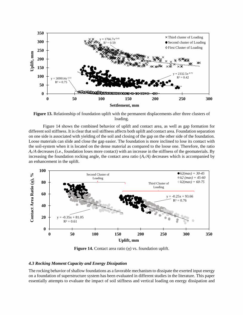
Figure 13. Relationship of foundation uplift with the permanent displacements after three clusters of
loading.
Figure 14 shows the combined behavior of uplift and contact area, as well as gap formation for
different soil stiffness. It is clear that soil stiffness affects both uplift and contact area. Foundation separation
on one side is associated with yielding of the soil and closing of the gap on the other side of the foundation.
Loose materials can slide and close the gap easier. The foundation is more inclined to lose its contact with
the soil-system when it is located on the dense material as compared to the loose one. Therefore, the ratio
Ac/A decreases (i.e., foundation loses more contact) with an increase in the stiffness of the geomaterials. By
increasing the foundation rocking angle, the contact area ratio (Ac/A) decreases which is accompanied by
an enhancement in the uplift.
Figure 14. Contact area ratio (η) vs. foundation uplift.
4.3 Rocking Moment Capacity and Energy Dissipation
The rocking behavior of shallow foundations as a favorable mechanism to dissipate the exerted input energy
on a foundation of superstructure system has been evaluated in different studies in the literature. This paper
essentially attempts to evaluate the impact of soil stiffness and vertical loading on energy dissipation and
y = 1766.7x-0.43
R² = 0.59
y = 2332.5x-0.72
R² = 0.42y = 309914x-2.51
R² = 0.75
0
50
100
150
200
250
300
350
0 50 100 150 200 250 300
Up
lift
, m
m
Settlement, mm
Third cluster of Loading
Second cluster of Loading
First Cluster of Loading
y = -0.35x + 81.05
R² = 0.61
y = -0.25x + 93.66
R² = 0.76
0
20
40
60
80
100
0 50 100 150 200 250 300 350
Co
nta
ct
Are
a R
ati
o (η
), %
Uplift, mm
k2(max) = 30-45
k2 (max) = 45-60
k2(max) = 60-75
Second Cluster of
Loading
Third Cluster of
Loading

mobilized moment during foundation rocking. Figure 15 depicts a schematic of the soil-foundation-
structure system during the lateral slow cyclic load. The free body diagram of forces at the center of the
soil-structure interface is also shown in Figure 15. The mobilized moment (MMobilized) about the center of
the foundation base can be determined via Equation (6):
𝑀𝑀𝑜𝑏𝑖𝑙𝑖𝑧𝑒𝑑 = 𝐹𝑟𝑒𝑎𝑐𝑡 . ℎ𝑐𝑔. cos(𝜃) − 𝑊𝑠. ℎ𝑐𝑔. sin(𝜃) (6)
where Freact is the reaction force obtained from the application of lateral cyclic displacement during rocking
of the foundation; hcg is the height of the center of gravity of the assembled foundation-superstructure
system; θ is the rotation of the structure due to the lateral cyclic displacement; and Ws is the weight of the
structure. Rotation-settlement and corresponding rotation-moment relationships for four FE cases with
different soil stiffness under application of different vertical loads (i.e., structures with different weights or
heights) are shown in Figure 16. It is observed that foundation rocking causes an accumulation of
permanent settlement at the center of the foundation. The permanent settlement gradually increases with an
increase in cyclic rotation of the foundation. Two structures with different sizes were supported by a
moderately stiff sandy material with K2(max) of 52 as shown in Figures 16a and b. Higher vertical load
(weight of structure) results in rapid yielding. Therefore, the foundation accumulates more displacement
for the heavier, taller structure (see Figures 16a and 16b). As judged by the enclosed area of the hysteresis
loops, the taller buildings located on softer soils are inclined to dissipate more input-energy in comparison
to the smaller buildings sitting on the stiffer material. Dissipation of energy is associated with yielding of
the soil and accumulation of permanent displacement. Furthermore, energy dissipation increases at higher
amplitudes of rotation (hysteresis loops become larger). The ultimate moment capacity, which is
accompanied by yielding of the soil beneath the foundation, is mobilized at lower values of rotations (0.5%
rad.).
Figure 15. Schematic of the soil-structure system and corresponding free body diagram of forces.
Similarly, Figures 16c and 16d demonstrate the rotational behavior of a heavy, high-rise structure
supported by dense (K2(max) = 68) and loose sandy material (K2(max) = 40), respectively. The results show that
the foundation displacement per cycle increases significantly for the loose material, and so, more energy is
dissipated (see Figure 16d).
Ws
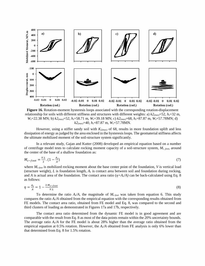
Figure 16. Rotation-moment hysteresis loops associated with the corresponding rotation-displacement
relationship for soils with different stiffness and structures with different weights: a) k2(max)=52, hs=32 m,
Ws=22.38 MN; b) k2(max)=52, hs=58.71 m, Ws=39.18 MN; c) k2(max)=68, hs=87.87 m, Ws=57.78MN; d)
k2(max)=40, hs=87.87 m, Ws=57.78MN.
However, using a stiffer sandy soil with K2(max) of 68, results in more foundation uplift and less
dissipation of energy as judged by the area enclosed in the hysteresis loops. The geomaterial stiffness affects
the ultimate mobilized moment of the soil-structure system significantly.
In a relevant study, Gajan and Kutter (2008) developed an empirical equation based on a number
of centrifuge model tests to calculate rocking moment capacity of a soil-structure system, Mc_foot, around
the center of the base of a shallow foundation as:
𝑀𝑐−𝑓𝑜𝑜𝑡 =𝑉.𝐿
2. (1 −
𝐴𝑐
𝐴) (7)
where Mc-foot is mobilized rocking moment about the base center point of the foundation, V is vertical load
(structure weight), L is foundation length, Ac is contact area between soil and foundation during rocking,
and A is actual area of the foundation. The contact area ratio (η=Ac/A) can be back-calculated using Eq. 8
as follows:
𝜂 =𝐴𝑐
𝐴= 1 −
2.𝑀𝑐−𝑓𝑜𝑜𝑡
𝑉.𝐿 (8)
To determine the ratio Ac/A, the magnitude of Mc-foot was taken from equation 6. This study
compares the ratio Ac/A obtained from the empirical equation with the corresponding results obtained from
FE models. The contact area ratio, obtained from FE model and Eq. 8, was compared to the second and
third clusters of loading as demonstrated in Figures 17a and 17b, respectively.
The contact area ratio determined from the dynamic FE model is in good agreement and are
comparable with the result from Eq. 8 as most of the data points remain within the 20% uncertainty bounds.
The average ratio Ac/A for the FE model is about 28% higher than the average ratio obtained from the
empirical equation at 0.5% rotation. However, the Ac/A obtained from FE analysis is only 6% lower than
that determined from Eq. 8 for 1.5% rotation.
a) b) c) d)

The rocking responses of a soil-structure system including mobilized moment, uplift, permanent
displacement, contact area, and energy dissipation have significant impacts on each other. As illustrated in
rotation-moment hysteresis in Figure 16, the rotational stiffness decreases as the foundation-superstructure
system is subjected to a higher amplitude of lateral loading. The relationship of uplift with the mobilized
moment at different rotations is shown in Figure 18. The mobilized moment is highly influenced by the
amount of uplift and it increases with an increase in foundation uplift. In other words, more uplift is
associated with more eccentricity which results in an enhancement in the mobilized moment.
Figure 17. Comparison of contact area ratio (η) obtained from FE models and the corresponding results
obtained from the empirical equation: a) at 0.5% rotation, and b) at 1.5% rotation.
Figure 18. Comparison of contact area ratio (η) obtained from FE models and the corresponding results
obtained from the empirical equation: a) at 0.5% rotation, and b) at 1.5% rotation.
y = 0.72x
R² = 0.89
SEE = 3.29
0
20
40
60
80
100
0 20 40 60 80 100
Em
pir
ica
l E
qu
ati
on
Con
tact
Are
a R
ati
o (η
), %
FE Model
Contact Area Ratio (η), %
+/- 20% Unertainty Bound
Line of Equality
y = 1.06x
R² = 0.74
SEE = 7.27
0
20
40
60
80
100
0 20 40 60 80 100
Em
pir
ical
Eq
uati
on
Con
tact
Are
a R
ati
o (η
), %
FE Model
Contact Area Ratio (η), %
+/- 20% Uncertainty Bound
Line of Equality
y = 21.81x + 97.93
R² = 0.59
y = 1.31x + 148.55
R² = 0.29
y = 1.11x + 76.56
R² = 0.24
0
100
200
300
400
500
600
0 50 100 150 200 250 300 350
Mo
bil
ized
Mo
men
t, M
N.m
Uplift, mm
First Cluster of Loading
Second Cluster of Loading
Third Cluster of Loading
a)
b)
As discussed earlier, two main parameters including soil stiffness and structure size (weight and
dimension) can affect the dissipated energy of a soil-structure system during rocking. The damping ratio
can also be estimated from the rotation-moment hysteresis loops. The following equation accounts for
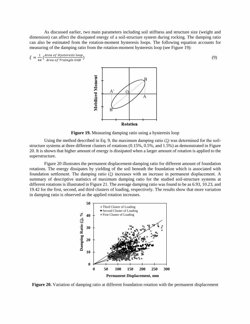
measuring of the damping ratio from the rotation-moment hysteresis loop (see Figure 19):
𝜉 =1
4𝜋(
𝐴𝑟𝑒𝑎 𝑜𝑓 𝐻𝑦𝑠𝑡𝑒𝑟𝑒𝑠𝑖𝑠 𝑙𝑜𝑜𝑝
𝐴𝑟𝑒𝑎 𝑜𝑓 𝑇𝑟𝑎𝑖𝑛𝑔𝑙𝑒 𝑂𝐴𝐵) (9)
Figure 19. Measuring damping ratio using a hysteresis loop
Using the method described in Eq. 9, the maximum damping ratio (ξ) was determined for the soil-
structure systems at three different clusters of rotations (0.15%, 0.5%, and 1.5%) as demonstrated in Figure
20. It is shown that higher amount of energy is dissipated when a larger amount of rotation is applied to the
superstructure.
Figure 20 illustrates the permanent displacement-damping ratio for different amount of foundation
rotations. The energy dissipates by yielding of the soil beneath the foundation which is associated with
foundation settlement. The damping ratio (ξ) increases with an increase in permanent displacement. A
summary of descriptive statistics of maximum damping ratio for the studied soil-structure systems at
different rotations is illustrated in Figure 21. The average damping ratio was found to be as 6.93, 10.23, and
19.42 for the first, second, and third clusters of loading, respectively. The results show that more variation
in damping ratio is observed as the applied rotation increases.
Figure 20. Variation of damping ratio at different foundation rotation with the permanent displacement
0
10
20
30
40
50
0 50 100 150 200 250 300
Da
mp
ing
Ra
tio
(ξ)
, %
Permanent Displacement, mm
Third Cluster of Loading
Second Cluster of Loading
First Cluster of Loading
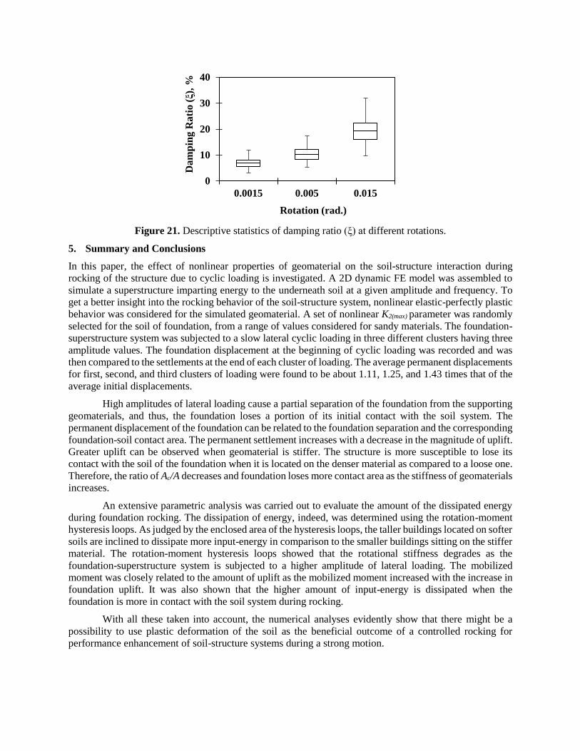
Figure 21. Descriptive statistics of damping ratio (ξ) at different rotations.
5. Summary and Conclusions
In this paper, the effect of nonlinear properties of geomaterial on the soil-structure interaction during
rocking of the structure due to cyclic loading is investigated. A 2D dynamic FE model was assembled to
simulate a superstructure imparting energy to the underneath soil at a given amplitude and frequency. To
get a better insight into the rocking behavior of the soil-structure system, nonlinear elastic-perfectly plastic
behavior was considered for the simulated geomaterial. A set of nonlinear K2(max) parameter was randomly
selected for the soil of foundation, from a range of values considered for sandy materials. The foundation-
superstructure system was subjected to a slow lateral cyclic loading in three different clusters having three
amplitude values. The foundation displacement at the beginning of cyclic loading was recorded and was
then compared to the settlements at the end of each cluster of loading. The average permanent displacements
for first, second, and third clusters of loading were found to be about 1.11, 1.25, and 1.43 times that of the
average initial displacements.
High amplitudes of lateral loading cause a partial separation of the foundation from the supporting
geomaterials, and thus, the foundation loses a portion of its initial contact with the soil system. The
permanent displacement of the foundation can be related to the foundation separation and the corresponding
foundation-soil contact area. The permanent settlement increases with a decrease in the magnitude of uplift.
Greater uplift can be observed when geomaterial is stiffer. The structure is more susceptible to lose its
contact with the soil of the foundation when it is located on the denser material as compared to a loose one.
Therefore, the ratio of Ac/A decreases and foundation loses more contact area as the stiffness of geomaterials
increases.
An extensive parametric analysis was carried out to evaluate the amount of the dissipated energy
during foundation rocking. The dissipation of energy, indeed, was determined using the rotation-moment
hysteresis loops. As judged by the enclosed area of the hysteresis loops, the taller buildings located on softer
soils are inclined to dissipate more input-energy in comparison to the smaller buildings sitting on the stiffer
material. The rotation-moment hysteresis loops showed that the rotational stiffness degrades as the
foundation-superstructure system is subjected to a higher amplitude of lateral loading. The mobilized
moment was closely related to the amount of uplift as the mobilized moment increased with the increase in
foundation uplift. It was also shown that the higher amount of input-energy is dissipated when the
foundation is more in contact with the soil system during rocking.
With all these taken into account, the numerical analyses evidently show that there might be a
possibility to use plastic deformation of the soil as the beneficial outcome of a controlled rocking for
performance enhancement of soil-structure systems during a strong motion.
0
10
20
30
40
0.0015 0.005 0.015D
am
pin
g R
ati
o (ξ)
, %
Rotation (rad.)

REFERENCES:
1. Housner GW. The behavior of inverted pendulum structures during earthquakes. Bulletin of the Seismological
Society of America. 1963; 53(2):403-17.
2. Koh A, Spanos PD, Roesset JM. Harmonic rocking of rigid block on flexible foundation. Journal of Engineering
Mechanics. 1986;112(11):1165–80.
3. Gottardi G, Butterfield R. The displacement of a model rigid surface footing on dense sand under general planar
loading. SOILS AND FOUNDATIONS. 1995; 35(3):71–82.
4. Zhang J, Makris N. Rocking response of free-standing blocks under cycloidal pulses. Journal of Engineering
Mechanics. 2001; 127(5):473–83.
5. Gajan S, Kutter BL, Phalen JD, Hutchinson TC, Martin GR. Centrifuge modeling of load-deformation behavior
of rocking shallow foundations. Soil Dynamics and Earthquake Engineering. 2005; 25(7–10):773–83.
6. Adamidis O, Gazetas G, Anastasopoulos I, Argyrou C. Equivalent-linear stiffness and damping in rocking of
circular and strip foundations. Bulletin of Earthquake Engineering. 2014;12(3):1177–200.
7. Fathi A. Numerical modeling of rocking of shallow foundations subjected to slow cyclic loading with
consideration of soil-structure interaction. Thesis, Sharif University of Technology, December 2014;
DOI:10.13140/RG.2.2.25852.85128.
8. Abadi SMS, Hosseini AM, Shahrabi MM. A Comparison between Results of the MSD Method and Finite Element
Modeling for Prediction of Undrained Settlement of Circular Shallow Foundations. 15th Pan-American Conf. on
Soil Mech. And Geotech. Eng. Buenos Aires, Argentina. 2015; DOI: 10.3233/978-1-61499-603-3-1480
9. Taghavi GA, Barari A, Fardad AP, Ibsen LB,. Development of optimum design from static response of pile–raft
interaction. Journal of Marine Science and Technology. 2015; 20(2):331–43. DOI:10.1007/s00773-014-0286-x
10. Haeri SM, Fathi A. Numerical modeling of rocking of shallow foundations subjected to slow cyclic loading with
consideration of soil-structure interaction. Fifth International Conference on Geotechnique, Construction,
Materials and Environment, Osaka, Japan, GEOMATE (CD-ROM), 2015; ID No. 5186.
11. Shahir H, Pak A, Ayoubi P. A performance-based approach for design of ground densification to mitigate
liquefaction. Soil Dynamics and Earthquake Engineering. 2016; 90:381–94.
12. Khosravi A, Rahimi M, Shahbazan P, Pak A, Gheibi A. Characterizing the variation of small strain shear modulus
for silt and sand during hydraulic hysteresis. E3S Web of Conferences. 2016; 9:14018.
13. Sharma K, Deng L. Field investigation of rocking shallow foundations on cohesive soil subjected to lateral cyclic
loads. The proceeding of the GEOOttawa 2017, Ottawa, Canada. 2017.
14. Barari A, Ibsen LB, Taghavi Ghalesari A, Larsen KA. Embedment Effects on Vertical Bearing Capacity of
Offshore Bucket Foundations on Cohesionless Soil. International Journal of Geomechanics. 2017;17(4):4016110,
DOI: 10.1061/(ASCE)GM.1943-5622.0000782.
15. Sharma K, Zhang W, Deng L. Rocking foundation on a natural clay subjected to lateral cyclic loads. Proceeding
of the 5th Geotechnical earthquake engineering and soil dynamics conference, June 10-13, 2018, Austin, TX,
USA. 2018.
16. Keshavarzi, B, Bakhshi, A. A new approach for consideration of earthquake low cycle fatigue phenomena on
reinforced concrete frames. Proceeding of 15th world conference on earthquake engineering. 2012.
17. Ayoubi P, Pak A. Liquefaction-induced settlement of shallow foundations on two-layered subsoil strata. Soil
Dynamics and Earthquake Engineering. 2017; 94:35–46.
18. Rahimi M, Khosravi A, Gheibi A, Mahdi Shahrabi M. Impact of Plastic Compression on the Small Strain Shear
Modulus of Unsaturated Silts. International Journal of Geomechanics. 2018;18(2):4017138.
19. Lemus L, Fathi A, Gholami A, Tirado C, Mazari M, Nazarian S. Geospatial Relationship of Intelligent
Compaction Measurement Values with In-Situ Testing for Quality Assessment of Geomaterials. International
Conference on Transportation and Development, 2018, ASCE (p. 293), DOI: 10.1061/9780784481554.030
20. FEMA. Prestandard and commentary for the seismic rehabilitation of buildings. FEMA 356, Washington, DC.
2000.
21. Anastasopoulos I, Gazetas G, Loli M, Apostolou M, Gerolymos N. Soil failure can be used for seismic protection
of structures. Bulletin of Earthquake Engineering. 2010; 8(2):309–26.
22. Hume G. Nepal Earthquake: My Experience in the Heart of Kathmandu. 2017; Retrieved from
https://www.huffingtonpost.com/gemma-hume/nepal-earthquake-my-experience-in-the-heart-of-
kathmandu_b_7189904.html.
23. Ayoubi P, Asimaki D, Mohammadi K. Basin effects in strong ground motion: A case study from the 2015 Gorkha,
Nepal earthquake, Geotechnical Earthquake Engineering and Soil Dynamics V, Austin, TX. 2018
24. Liu W, Hutchinson TC, Kutter BL. Balancing the beneficial contributions of foundation rocking and structural
yielding in moment-frame and frame-wall building systems. In: 4th ECCOMAS Thematic Conference on
Computational Methods in Structural Dynamics and Earthquake Engineering. 4th ECCOMAS Thematic
Conference on Computational Methods in Structural Dynamics and Earthquake Engineering; 2013.
25. Gajan S, Kutter BL. Capacity, settlement, and energy dissipation of shallow footings subjected to rocking. Journal
of Geotechnical and Geoenvironmental Engineering. 2008;134(8):1129–41.
26. Meek JW. Effects of foundation tipping on dynamic response. Journal of the Structural Division. 1975;101(ST7).
27. Mylonakis G, Gazetas G. Seismic soil-structure interaction: beneficial or detrimental. Journal of Earthquake
Engineering. 2000; 4(03), 277-301.
28. Bartlett PE. Foundation rocking on clay soil. Doctoral dissertation, Department of Civil Engineering, University
of Auckland. 1976.
29. Xia C, Hanson RD. Influence of ADAS Element Parameters on Building Seismic Response. Journal of Structural
Engineering. 1992;118(7):1903–18.
30. Martin GR, Lam IP. Earthquake resistant design of foundations-retrofit of existing foundations. In: ISRM
International Symposium. International Society for Rock Mechanics. 2000.
31. Pecker A, Pender M. Earthquake resistant design of foundations: New construction. 2000; In ISRM International
Symposium. International Society for Rock Mechanics; ISRM-IS-2000-007.
32. Faccioli E, Paolucci R, Vivero G. Investigation of seismic soil-footing interaction by large scale tests and
analytical models. International Conferences on Recent Advances in Geotechnical Earthquake Engineering and
Soil Dynamics. 2001.
33. Jafarzadeh F, Farahi JH, Sehizadeh M, Joshaghani M, Yousfi S. Evaluation of Dynamic Response and
Vulnerability of Tehran Buried Gas Network Pipelines in Slopes by in Situ Explorations, 1g Shaking Table Tests,
and Numerical Modeling. Proceedings of the U.S.-Iran Seismic Workshop. Publisher: Pacific Earthquake
Engineering Research Center Headquarters at the University of Califronia; 2013
34. Haeri SM, Hosseini AM, Shahrabi MM, Soleymani S. Comparison of strength characteristics of gorgan loessial
soil improved by nano-silica, lime and portland cement. In 15th Pan American Conference on Soil Mechanics
and Geotechnical Engineering. 2015.
35. Garnier J, Gaudin C, Springman SM, Culligan PJ, Goodings D, Konig D, Kutter B, Phillips R, Randolph MF and
Thorel L. Catalogue of scaling laws and similitude questions in geotechnical centrifuge modelling. International
Journal of Physical Modelling in Geotechnics. 2007; 7(3), 1.
36. Deng L, Kutter BL, Kunnath SK. Centrifuge modeling of bridge systems designed for rocking foundations.
Journal of Geotechnical and Geoenvironmental Engineering. 2012;138(3):335–44.
37. Kutter BL. Workshop on modeling of nonlinear cyclic load-deformation behavior of shallow foundations.
University of California, Davis. University of California, Berkeley, Pacific Earthquake Engineering Research
Center, College of Engineering. 2006.
38. Abate G, Massimino MR, Maugeri M, Muir Wood D. Numerical modelling of a shaking table test for soil-
foundation-superstructure interaction by means of a soil constitutive model implemented in a FEM code.
Geotechnical and Geological Engineering. 2010; 28(1):37–59.
39. Anastasopoulos I, Gelagoti F, Kourkoulis R, Gazetas G. Simplified Constitutive Model for Simulation of Cyclic
Response of Shallow Foundations: Validation against Laboratory Tests. Journal of Geotechnical and
Geoenvironmental Engineering. 2011; 137(12):1154–68.
40. Panagiotidou AI, Gazetas G, Gerolymos N. Pushover and seismic response of foundations on stiff clay: Analysis
with P-delta effects. Earthquake Spectra. 2012; 28(4):1589–618.
41. Coe JT, Mahvelati S, Stuedlein AW, Asabere P, Gianella TN. Time-rate variation of the shear wave velocity (site
stiffness) following blast-induced liquefaction. In: Geo-Chicago 2016. Reston, VA: American Society of Civil
Engineers; 2016; p. 904–13. Doi:10.1061/9780784480144.090
42. Keshavarzi B, Kim YR. A. viscoelastic-based model for predicting the strength of asphalt concrete in direct
tension. Construction and Building Materials. 2016; 122:721–7.
43. Ashtiani RS, Little DN, Rashidi M. Neural network based model for estimation of the level of anisotropy of
unbound aggregate systems. Transportation Geotechnics. 2018; 15:4–12.
https://doi.org/10.1016/j.trgeo.2018.02.002.
44. Kazemi SF, Sebaaly PE, Siddharthan RV, Hajj EY, Hand AJ, Ahsanuzzaman M. Dynamic pavement response
coefficient to estimate the impact of variation in dynamic vehicle load. Tenth International Conference on the
Bearing Capacity of Roads, Railways, and Airfield. 2017.

45. Mahvelati S, Coe JT. The Use of Two dimensional (2D) multichannel analysis of surface waves (MASW) testing
to evaluate the geometry of an unknown bridge foundation. In: Geotechnical Frontiers 2017. p. 657–66.
http://ascelibrary.org/doi/10.1061/9780784480441.069
46. Tirado C, Gamez-Rios KY, Fathi A, Mazari M, Nazarian S. Simulation of lightweight deflectometer
measurements considering nonlinear behavior of geomaterials. Transportation Research Record (TRR): Journal
of the Transportation Research Board. 2017; 2641:58–65. http://trrjournalonline.trb.org/doi/10.3141/2641-08
47. Rashidi M, Haeri SM. Evaluation of behaviors of earth and rockfill dams during construction and initial
impounding using instrumentation data and numerical modeling. Journal of Rock Mechanics and Geotechnical
Engineering. 2017; 9(4):709–25. https://doi.org/10.1016/j.jrmge.2016.12.003.
48. Rashidi M, Azizyan G, Heidari M,. Numerical analysis and monitoring of an embankment dam during
construction and first impounding (case study: Siah Sang dam). Scientia Iranica. 2017.
http://scientiairanica.sharif.edu/article_4181.html
49. Fathi A, Tirado C, Gholamy A, Lemus L, Mazari M, Nazarian S. Consideration of depth of influence in
implementation of intelligent compaction in earthwork quality management. In Washington DC, United States:
Transportation Research Board, 2018 Annual Meeting; 2018. No. 18-02100, https://trid.trb.org/view/1495174
50. Seed HB, Idriss IM. Soil moduli and damping factors for dynamic response analysis. EERC. 1970;
https://ci.nii.ac.jp/naid/10022026877/
51. Shibata T, Soelarno DS. Stress-strain characteristics of sands under cyclic loading. Proceedings of the Japan
Society of Civil Engineers. 1975;1975(239):57–65.
52. Seed HB, Wong RT, Idriss IM, Tokimatsu K. Moduli and damping factors for dynamic analyses of cohesionless
soils. Journal of Geotechnical Engineering. 1986; 112(11):1016–32.
53. Rayleigh JWS, Lindsay RB. The Theory of Sound. Dover Publications, New York. 1945.
54. Londono JM, Wagg DJ, Neild SA. Estimating the overall damping ratio in structures with brace–damper systems.
In Proceedings of the 15th World Conference on Earthquake Engineering. 2012; 15WCEE.
55. Bernal D, Dohler M, Kojidi SM, Kwan K, Liu Y. First mode damping ratios for buildings. Earthquake Spectra.
2015; 31(1), 367-381.
56. Park D, and Hashash YMA. Soil damping formulation in nonlinear time domain site response analysis. Journal
of Earthquake Engineering. 2004; 8(2):249.
57. Rosebrook KR, Kutter BL. Soil-foundation-structure interaction: Shallow foundations centrifuge data report for
KRR02, Earthquake Engineering Research Center, University of California, Davis, 2001; EEC-971568, Peer
2061999, 2142000.
58. Hertz, HR. Ueber die Berührung fester elastischer Körper (On the contact between elastic bodies). Journal für die
reine und angewandte Mathematik, 1882(92); pp. 156–171.