performance of harbour structures in andaman islands
TRANSCRIPT
Engineering Structures 30 (2008) 174–182www.elsevier.com/locate/engstruct
Performance of harbour structures in Andaman Islands during 2004Sumatra earthquake
Goutam Mondal, Durgesh C. Rai∗
Department of Civil Engineering, Indian Institute of Technology Kanpur, 208016, India
Received 29 July 2006; received in revised form 8 December 2006; accepted 18 March 2007Available online 26 April 2007
Abstract
The devastating Mw 9.1 Sumatra earthquake on 26 December 2004 and subsequent tsunami caused severe damages to harbour structureswhich caused delay in supply of relief work in the earthquake and tsunami affected areas in Andaman Islands, India. Major structural damagewas observed at the construction joints due to pounding of two portions of jetties and at the top of reinforced concrete piles, especially shortpiles. Inadequate structural design and reinforcement detailing along with poor maintenance of these structures were primarily responsible forthe severe damages. Other geotechnical aspects, e.g. liquefaction of soils, slope-stability failure, etc., were also responsible for severe damage tothese structures. Appropriate seismic design provisions in applicable codes and their implementation are necessary to ensure satisfactory structuralresponse for uninterrupted services at harbours in seismically active zones, especially those in developing countries.c© 2007 Elsevier Ltd. All rights reserved.
Keywords: Sumatra earthquake; Andaman Islands; Harbour structures; Jetties; Pounding damage; Short-column effect; Liquefaction; Slope stability
1. Introduction
Wharves and jetties are lifeline structures as they provide acost effective method for transporting large quantities of goodsand raw materials into and out of a region. These harbourstructures also play a significant role in the transportationsystem in terms of evacuation of people before and afternatural disasters like earthquakes and tsunami. Further, theseare useful to supply relief materials after a disaster whenother transportation systems fail to deliver. Similar roles wereaccomplished by some of the less damaged ports and jettiesin Andaman & Nicobar (A&N) Islands after 26 December2004 when the great Sumatra earthquake of magnitude Mw
9.1 caused a devastating tsunami in the Indian Ocean. Thisearthquake occurred due to subduction of the Indian plate underthe Burmese micro-plate and 283 106 people in the South andSoutheast Asia died mainly due to subsequent tsunami [1].The subduction zone was characterized by a NNW-SSE arcuatetrench running parallel to the western side of Sumatra and theA&N Islands [2]. Apart from inundation due to the tsunami,
∗ Corresponding author. Tel.: +91 512 259 7717; fax: +91 512 259 7794.E-mail address: [email protected] (D.C. Rai).
0141-0296/$ - see front matter c© 2007 Elsevier Ltd. All rights reserved.doi:10.1016/j.engstruct.2007.03.015
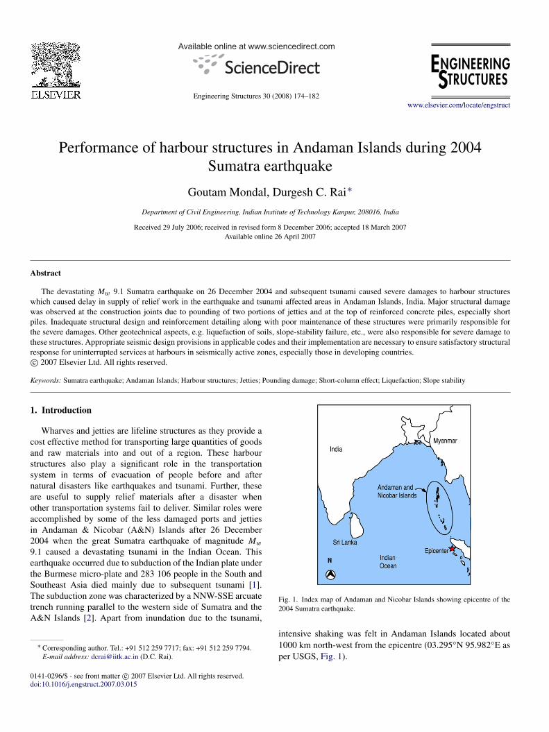
Fig. 1. Index map of Andaman and Nicobar Islands showing epicentre of the2004 Sumatra earthquake.
intensive shaking was felt in Andaman Islands located about1000 km north-west from the epicentre (03.295◦N 95.982◦E asper USGS, Fig. 1).
G. Mondal, D.C. Rai / Engineering Structures 30 (2008) 174–182 175
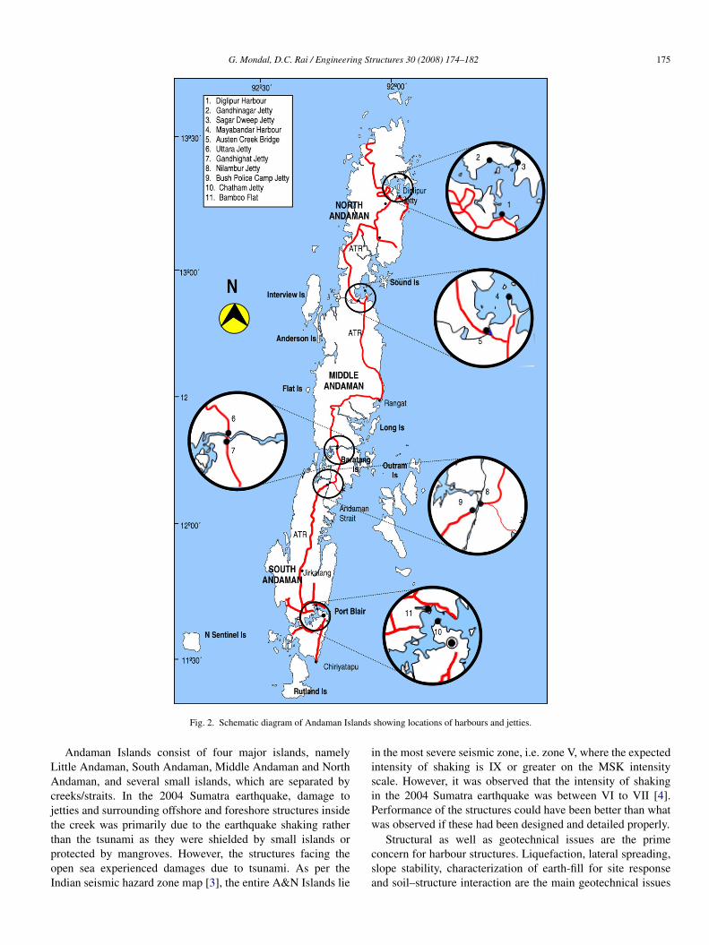
Fig. 2. Schematic diagram of Andaman Islands showing locations of harbours and jetties.
Andaman Islands consist of four major islands, namelyLittle Andaman, South Andaman, Middle Andaman and NorthAndaman, and several small islands, which are separated bycreeks/straits. In the 2004 Sumatra earthquake, damage tojetties and surrounding offshore and foreshore structures insidethe creek was primarily due to the earthquake shaking ratherthan the tsunami as they were shielded by small islands orprotected by mangroves. However, the structures facing theopen sea experienced damages due to tsunami. As per theIndian seismic hazard zone map [3], the entire A&N Islands lie
in the most severe seismic zone, i.e. zone V, where the expectedintensity of shaking is IX or greater on the MSK intensityscale. However, it was observed that the intensity of shakingin the 2004 Sumatra earthquake was between VI to VII [4].Performance of the structures could have been better than whatwas observed if these had been designed and detailed properly.
Structural as well as geotechnical issues are the primeconcern for harbour structures. Liquefaction, lateral spreading,slope stability, characterization of earth-fill for site responseand soil–structure interaction are the main geotechnical issues
176 G. Mondal, D.C. Rai / Engineering Structures 30 (2008) 174–182
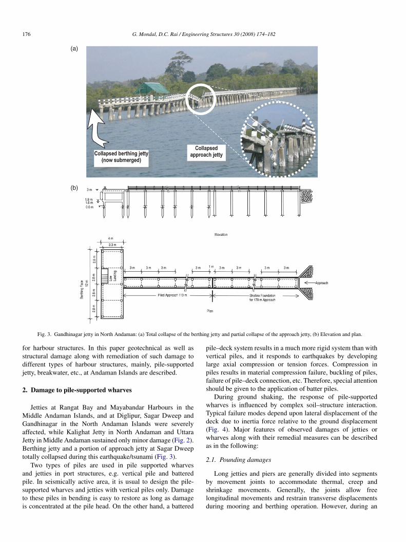
Fig. 3. Gandhinagar jetty in North Andaman: (a) Total collapse of the berthing jetty and partial collapse of the approach jetty, (b) Elevation and plan.
for harbour structures. In this paper geotechnical as well asstructural damage along with remediation of such damage todifferent types of harbour structures, mainly, pile-supportedjetty, breakwater, etc., at Andaman Islands are described.
2. Damage to pile-supported wharves
Jetties at Rangat Bay and Mayabandar Harbours in theMiddle Andaman Islands, and at Diglipur, Sagar Dweep andGandhinagar in the North Andaman Islands were severelyaffected, while Kalighat Jetty in North Andaman and UttaraJetty in Middle Andaman sustained only minor damage (Fig. 2).Berthing jetty and a portion of approach jetty at Sagar Dweeptotally collapsed during this earthquake/tsunami (Fig. 3).
Two types of piles are used in pile supported wharvesand jetties in port structures, e.g. vertical pile and batteredpile. In seismically active area, it is usual to design the pile-supported wharves and jetties with vertical piles only. Damageto these piles in bending is easy to restore as long as damageis concentrated at the pile head. On the other hand, a battered
pile–deck system results in a much more rigid system than withvertical piles, and it responds to earthquakes by developinglarge axial compression or tension forces. Compression inpiles results in material compression failure, buckling of piles,failure of pile–deck connection, etc. Therefore, special attentionshould be given to the application of batter piles.
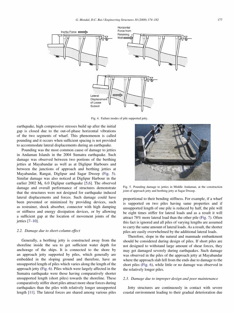
During ground shaking, the response of pile-supportedwharves is influenced by complex soil–structure interaction.Typical failure modes depend upon lateral displacement of thedeck due to inertia force relative to the ground displacement(Fig. 4). Major features of observed damages of jetties orwharves along with their remedial measures can be describedas in the following:
2.1. Pounding damages
Long jetties and piers are generally divided into segmentsby movement joints to accommodate thermal, creep andshrinkage movements. Generally, the joints allow freelongitudinal movements and restrain transverse displacementsduring mooring and berthing operation. However, during an
G. Mondal, D.C. Rai / Engineering Structures 30 (2008) 174–182 177
Fig. 4. Failure modes of pile supported jetty.
earthquake, high compressive stresses build up after the initialgap is closed due to the out-of-phase horizontal vibrationsof the two segments of wharf. This phenomenon is calledpounding and it occurs when sufficient spacing is not providedto accommodate lateral displacements during an earthquake.
Pounding was the most common cause of damage to jettiesin Andaman Islands in the 2004 Sumatra earthquake. Suchdamage was observed between two portions of the berthingjetties at Mayabandar as well as at Diglipur Harbours andbetween the junctions of approach and berthing jetties atMayabandar, Rangat, Diglipur and Sagar Dweep (Fig. 5).Similar damage was also noticed at Diglipur Harbour in theearlier 2002 ML 6.0 Diglipur earthquake [5,6]. The observeddamage and overall performance of structures demonstratethat the structures were not designed for earthquake inducedlateral displacements and forces. Such damage could havebeen prevented or minimized by providing devices, suchas restrainer, shock absorber, connector with high dampingor stiffness and energy dissipation devices, or by allowinga sufficient gap at the location of movement joints of thejetties [7–10].
2.2. Damage due to short-column effect
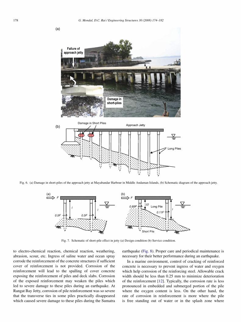
Generally, a berthing jetty is constructed away from theshoreline inside the sea to get sufficient water depth foranchorage of the ships. It is connected to the shore byan approach jetty supported by piles, which generally areembedded in the sloping ground and therefore, have anunsupported length of piles which varies along the length of theapproach jetty (Fig. 6). Piles which were largely affected in theSumatra earthquake were those having comparatively shorterunsupported length (short piles) towards the shoreline. Thesecomparatively stiffer short piles attract more shear forces duringearthquakes than the piles with relatively longer unsupportedlength [11]. The lateral forces are shared among various piles
Fig. 5. Pounding damage to jetties in Middle Andaman, at the constructionjoint of approach jetty and berthing jetty at Sagar Dweep.
proportional to their bending stiffness. For example, if a wharfis supported on two piles having same properties and ifunsupported length of one pile is reduced by half, the pile willbe eight times stiffer for lateral loads and as a result it willattract 78% more lateral load than the other pile (Fig. 7). Oftenthis fact is ignored and all piles of varying lengths are assumedto carry the same amount of lateral loads. As a result, the shorterpiles are easily overwhelmed by the additional lateral loads.
Therefore, slope in the natural and manmade embankmentshould be considered during design of piles. If short piles arenot designed to withstand large amount of shear forces, theymay get damaged severely during earthquakes. Such damagewas observed in the piles of the approach jetty at Mayabandarwhere the approach slab fell from the ends due to damage to theshort piles (Fig. 6), while little or no damage was observed inthe relatively longer piles.
2.3. Damage due to improper design and poor maintenance
Jetty structures are continuously in contact with severecoastal environment leading to their gradual deterioration due
178 G. Mondal, D.C. Rai / Engineering Structures 30 (2008) 174–182
Fig. 6. (a) Damage in short-piles of the approach jetty at Mayabandar Harbour in Middle Andaman Islands, (b) Schematic diagram of the approach jetty.
Fig. 7. Schematic of short-pile effect in jetty (a) Design condition (b) Service condition.
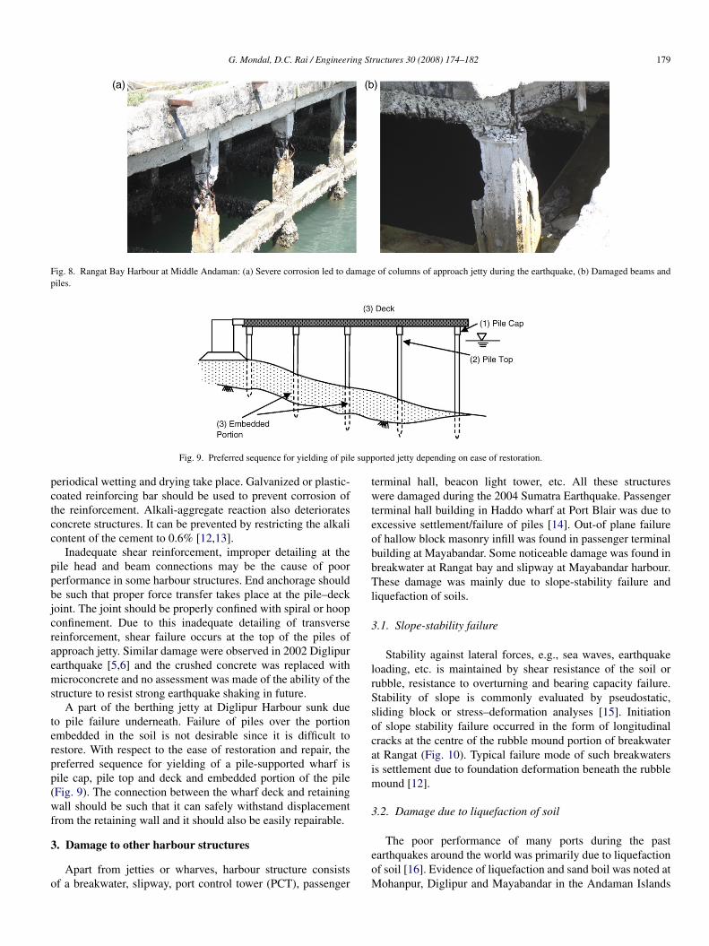
to electro-chemical reaction, chemical reaction, weathering,abrasion, scour, etc. Ingress of saline water and ocean spraycorrode the reinforcement of the concrete structures if sufficientcover of reinforcement is not provided. Corrosion of thereinforcement will lead to the spalling of cover concreteexposing the reinforcement of piles and deck slabs. Corrosionof the exposed reinforcement may weaken the piles whichled to severe damage to these piles during an earthquake. AtRangat Bay Jetty, corrosion of pile reinforcement was so severethat the transverse ties in some piles practically disappearedwhich caused severe damage to these piles during the Sumatra
earthquake (Fig. 8). Proper care and periodical maintenance isnecessary for their better performance during an earthquake.
In a marine environment, control of cracking of reinforcedconcrete is necessary to prevent ingress of water and oxygenwhich help corrosion of the reinforcing steel. Allowable crackwidth should be less than 0.25 mm to minimize deteriorationof the reinforcement [12]. Typically, the corrosion rate is lesspronounced in embedded and submerged portion of the pilewhere the oxygen content is less. On the other hand, therate of corrosion in reinforcement is more where the pileis free standing out of water or in the splash zone where
G. Mondal, D.C. Rai / Engineering Structures 30 (2008) 174–182 179
Fig. 8. Rangat Bay Harbour at Middle Andaman: (a) Severe corrosion led to damage of columns of approach jetty during the earthquake, (b) Damaged beams andpiles.
Fig. 9. Preferred sequence for yielding of pile supported jetty depending on ease of restoration.
periodical wetting and drying take place. Galvanized or plastic-coated reinforcing bar should be used to prevent corrosion ofthe reinforcement. Alkali-aggregate reaction also deterioratesconcrete structures. It can be prevented by restricting the alkalicontent of the cement to 0.6% [12,13].
Inadequate shear reinforcement, improper detailing at thepile head and beam connections may be the cause of poorperformance in some harbour structures. End anchorage shouldbe such that proper force transfer takes place at the pile–deckjoint. The joint should be properly confined with spiral or hoopconfinement. Due to this inadequate detailing of transversereinforcement, shear failure occurs at the top of the piles ofapproach jetty. Similar damage were observed in 2002 Diglipurearthquake [5,6] and the crushed concrete was replaced withmicroconcrete and no assessment was made of the ability of thestructure to resist strong earthquake shaking in future.
A part of the berthing jetty at Diglipur Harbour sunk dueto pile failure underneath. Failure of piles over the portionembedded in the soil is not desirable since it is difficult torestore. With respect to the ease of restoration and repair, thepreferred sequence for yielding of a pile-supported wharf ispile cap, pile top and deck and embedded portion of the pile(Fig. 9). The connection between the wharf deck and retainingwall should be such that it can safely withstand displacementfrom the retaining wall and it should also be easily repairable.
3. Damage to other harbour structures
Apart from jetties or wharves, harbour structure consistsof a breakwater, slipway, port control tower (PCT), passenger
terminal hall, beacon light tower, etc. All these structureswere damaged during the 2004 Sumatra Earthquake. Passengerterminal hall building in Haddo wharf at Port Blair was due toexcessive settlement/failure of piles [14]. Out-of plane failureof hallow block masonry infill was found in passenger terminalbuilding at Mayabandar. Some noticeable damage was found inbreakwater at Rangat bay and slipway at Mayabandar harbour.These damage was mainly due to slope-stability failure andliquefaction of soils.
3.1. Slope-stability failure
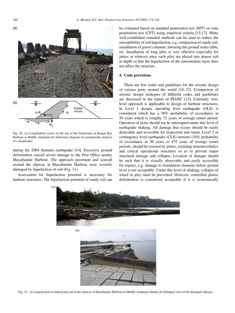
Stability against lateral forces, e.g., sea waves, earthquakeloading, etc. is maintained by shear resistance of the soil orrubble, resistance to overturning and bearing capacity failure.Stability of slope is commonly evaluated by pseudostatic,sliding block or stress–deformation analyses [15]. Initiationof slope stability failure occurred in the form of longitudinalcracks at the centre of the rubble mound portion of breakwaterat Rangat (Fig. 10). Typical failure mode of such breakwatersis settlement due to foundation deformation beneath the rubblemound [12].
3.2. Damage due to liquefaction of soil
The poor performance of many ports during the pastearthquakes around the world was primarily due to liquefactionof soil [16]. Evidence of liquefaction and sand boil was noted atMohanpur, Diglipur and Mayabandar in the Andaman Islands
180 G. Mondal, D.C. Rai / Engineering Structures 30 (2008) 174–182
Fig. 10. (a) Longitudinal cracks on the top of the breakwater at Rangat BayHarbour at Middle Andaman (b) Schematic diagram for pseudostatic analysisof a breakwater.
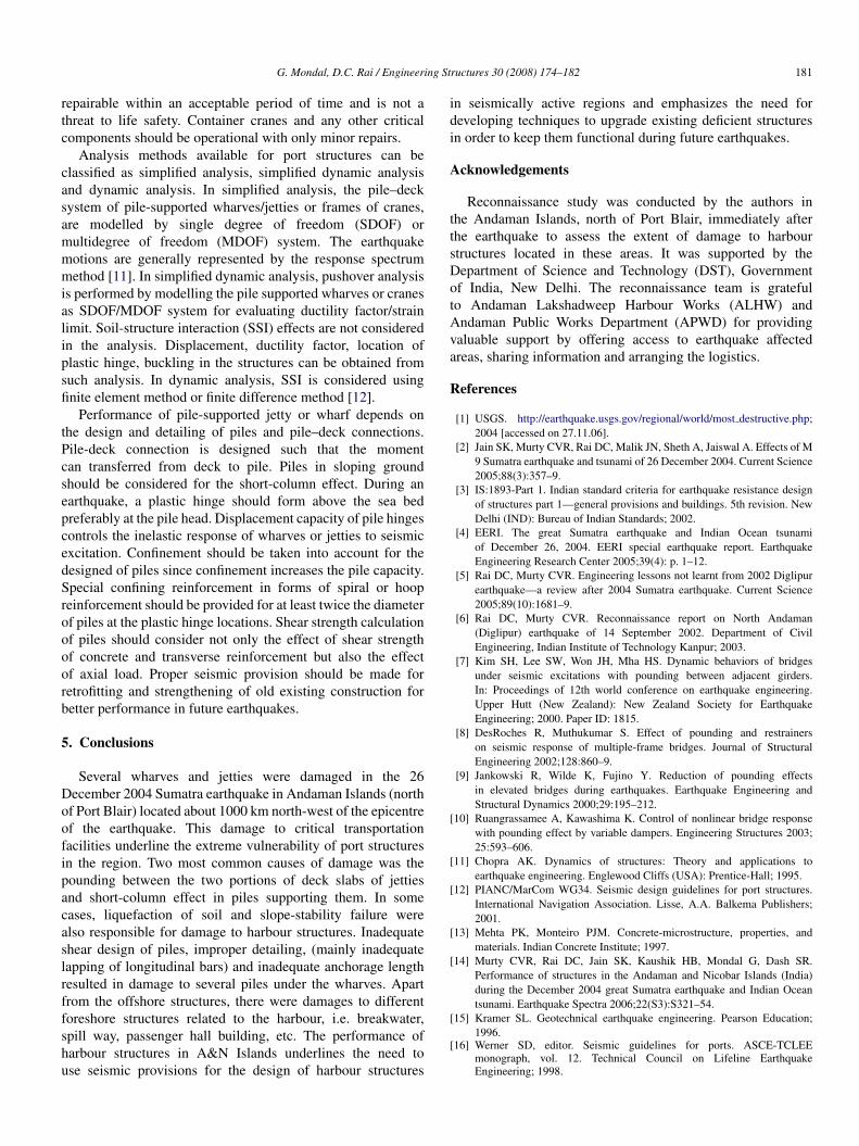
during the 2004 Sumatra earthquake [14]. Excessive grounddeformation caused severe damage to the Post Office nearbyMayabandar Harbour. The approach pavement and seawallaround the slipway at Mayabandar Harbour were severelydamaged by liquefaction of soil (Fig. 11).
Assessment for liquefaction potential is necessary forharbour structures. The liquefaction potential of sandy soil can
be evaluated based on standard penetration test (SPT) or conepenetration test (CPT) using empirical criteria [15,17]. Manywell-established remedial methods can be used to reduce thesusceptibility of soil liquefaction, e.g. compaction of sandy soil,installation of gravel columns, lowering the ground water table,etc. Installation of long piles is very effective especially forjetties or wharves since such piles are placed into denser soilat depth so that the liquefaction of the intermediate layer doesnot affect the structure.
4. Code provisions
There are few codes and guidelines for the seismic designof various ports around the world [18–22]. Comparison ofseismic design strategies of different codes and guidelinesare discussed in the report of PIANC [12]. Currently, two-level approach is applicable to design of harbour structures.In Level 1 design, operating level earthquake (OLE) isconsidered which has a 50% probability of exceedance in50 years which is roughly 72 years of average return period.Operation of ports should not be interrupted under this level ofearthquake shaking. All damage that occurs should be easilydetectable and accessible for inspection and repair. Level 2 orcontingency level earthquake (CLE) motions (10% probabilityof exceedance in 50 years or 475 years of average returnperiod), should be resisted by jetties, retaining structures/dykesand critical operational structures so as to prevent majorstructural damage and collapse. Location of damage shouldbe such that it is visually observable and easily accessiblefor repairs, e.g. damage to foundation elements below groundlevel is not acceptable. Under this level of shaking, collapse ofwharf or jetty must be prevented. However, controlled plasticdeformation is considered acceptable if it is economically
Fig. 11. (a) Liquefaction of underlying soil in the slipway at Mayabandar Harbour in Middle Andaman Islands (b) Enlarged view of the damaged slipway.
G. Mondal, D.C. Rai / Engineering Structures 30 (2008) 174–182 181
repairable within an acceptable period of time and is not athreat to life safety. Container cranes and any other criticalcomponents should be operational with only minor repairs.
Analysis methods available for port structures can beclassified as simplified analysis, simplified dynamic analysisand dynamic analysis. In simplified analysis, the pile–decksystem of pile-supported wharves/jetties or frames of cranes,are modelled by single degree of freedom (SDOF) ormultidegree of freedom (MDOF) system. The earthquakemotions are generally represented by the response spectrummethod [11]. In simplified dynamic analysis, pushover analysisis performed by modelling the pile supported wharves or cranesas SDOF/MDOF system for evaluating ductility factor/strainlimit. Soil-structure interaction (SSI) effects are not consideredin the analysis. Displacement, ductility factor, location ofplastic hinge, buckling in the structures can be obtained fromsuch analysis. In dynamic analysis, SSI is considered usingfinite element method or finite difference method [12].
Performance of pile-supported jetty or wharf depends onthe design and detailing of piles and pile–deck connections.Pile-deck connection is designed such that the momentcan transferred from deck to pile. Piles in sloping groundshould be considered for the short-column effect. During anearthquake, a plastic hinge should form above the sea bedpreferably at the pile head. Displacement capacity of pile hingescontrols the inelastic response of wharves or jetties to seismicexcitation. Confinement should be taken into account for thedesigned of piles since confinement increases the pile capacity.Special confining reinforcement in forms of spiral or hoopreinforcement should be provided for at least twice the diameterof piles at the plastic hinge locations. Shear strength calculationof piles should consider not only the effect of shear strengthof concrete and transverse reinforcement but also the effectof axial load. Proper seismic provision should be made forretrofitting and strengthening of old existing construction forbetter performance in future earthquakes.
5. Conclusions
Several wharves and jetties were damaged in the 26December 2004 Sumatra earthquake in Andaman Islands (northof Port Blair) located about 1000 km north-west of the epicentreof the earthquake. This damage to critical transportationfacilities underline the extreme vulnerability of port structuresin the region. Two most common causes of damage was thepounding between the two portions of deck slabs of jettiesand short-column effect in piles supporting them. In somecases, liquefaction of soil and slope-stability failure werealso responsible for damage to harbour structures. Inadequateshear design of piles, improper detailing, (mainly inadequatelapping of longitudinal bars) and inadequate anchorage lengthresulted in damage to several piles under the wharves. Apartfrom the offshore structures, there were damages to differentforeshore structures related to the harbour, i.e. breakwater,spill way, passenger hall building, etc. The performance ofharbour structures in A&N Islands underlines the need touse seismic provisions for the design of harbour structures
in seismically active regions and emphasizes the need fordeveloping techniques to upgrade existing deficient structuresin order to keep them functional during future earthquakes.
Acknowledgements
Reconnaissance study was conducted by the authors inthe Andaman Islands, north of Port Blair, immediately afterthe earthquake to assess the extent of damage to harbourstructures located in these areas. It was supported by theDepartment of Science and Technology (DST), Governmentof India, New Delhi. The reconnaissance team is gratefulto Andaman Lakshadweep Harbour Works (ALHW) andAndaman Public Works Department (APWD) for providingvaluable support by offering access to earthquake affectedareas, sharing information and arranging the logistics.
References
[1] USGS. http://earthquake.usgs.gov/regional/world/most destructive.php;2004 [accessed on 27.11.06].
[2] Jain SK, Murty CVR, Rai DC, Malik JN, Sheth A, Jaiswal A. Effects of M9 Sumatra earthquake and tsunami of 26 December 2004. Current Science2005;88(3):357–9.
[3] IS:1893-Part 1. Indian standard criteria for earthquake resistance designof structures part 1—general provisions and buildings. 5th revision. NewDelhi (IND): Bureau of Indian Standards; 2002.
[4] EERI. The great Sumatra earthquake and Indian Ocean tsunamiof December 26, 2004. EERI special earthquake report. EarthquakeEngineering Research Center 2005;39(4): p. 1–12.
[5] Rai DC, Murty CVR. Engineering lessons not learnt from 2002 Diglipurearthquake—a review after 2004 Sumatra earthquake. Current Science2005;89(10):1681–9.
[6] Rai DC, Murty CVR. Reconnaissance report on North Andaman(Diglipur) earthquake of 14 September 2002. Department of CivilEngineering, Indian Institute of Technology Kanpur; 2003.
[7] Kim SH, Lee SW, Won JH, Mha HS. Dynamic behaviors of bridgesunder seismic excitations with pounding between adjacent girders.In: Proceedings of 12th world conference on earthquake engineering.Upper Hutt (New Zealand): New Zealand Society for EarthquakeEngineering; 2000. Paper ID: 1815.
[8] DesRoches R, Muthukumar S. Effect of pounding and restrainerson seismic response of multiple-frame bridges. Journal of StructuralEngineering 2002;128:860–9.
[9] Jankowski R, Wilde K, Fujino Y. Reduction of pounding effectsin elevated bridges during earthquakes. Earthquake Engineering andStructural Dynamics 2000;29:195–212.
[10] Ruangrassamee A, Kawashima K. Control of nonlinear bridge responsewith pounding effect by variable dampers. Engineering Structures 2003;25:593–606.
[11] Chopra AK. Dynamics of structures: Theory and applications toearthquake engineering. Englewood Cliffs (USA): Prentice-Hall; 1995.
[12] PIANC/MarCom WG34. Seismic design guidelines for port structures.International Navigation Association. Lisse, A.A. Balkema Publishers;2001.
[13] Mehta PK, Monteiro PJM. Concrete-microstructure, properties, andmaterials. Indian Concrete Institute; 1997.
[14] Murty CVR, Rai DC, Jain SK, Kaushik HB, Mondal G, Dash SR.Performance of structures in the Andaman and Nicobar Islands (India)during the December 2004 great Sumatra earthquake and Indian Oceantsunami. Earthquake Spectra 2006;22(S3):S321–54.
[15] Kramer SL. Geotechnical earthquake engineering. Pearson Education;1996.
[16] Werner SD, editor. Seismic guidelines for ports. ASCE-TCLEEmonograph, vol. 12. Technical Council on Lifeline EarthquakeEngineering; 1998.

182 G. Mondal, D.C. Rai / Engineering Structures 30 (2008) 174–182
[17] Ishihara K. Soil behaviour in earthquake geotechnics. Oxford: ClaredonPress; 1996.
[18] Ministry of Transport Japan (ed.). Design standard for port and harbourfacilities and commentaries, Japan Port and Harbour Association; 1999[in Japanese]. English edition by the Overseas Coastal Area DevelopmentInstitute of Japan; 2001.
[19] MOTEMS. Marine Oil Terminal Engineering and Mainte-nance Standards, California State Lands Commission. Websitehttp://www.slc.ca.gov/Division Pages/MFD/MOTEMS/MOTEMS.htm;2002 [accessed on 25.03.06].
[20] Ferritto JM, Dickenson SE, Priestley MJN, Werner SD, Taylor CE.Seismic criteria for California marine oil terminals. Technical report TR-2103-SHR. Naval Facilities Engineering Service Center, Port Hueneme;1999.
[21] EAU 1996. Recommendations of the committee for waterfront structures,harbours and waterways. 7th ed. Berlin: Ernst & Sohn.
[22] POLA Code for Seismic Design, Upgrade, and Repair ofContainer Wharves. The Ports of Los Angeles. Website at:http://www.polaseismic.org/polacode.htm; 2004 [accessed on 25.03.06].